JP4535697B2 - Endoscope device for light scattering observation of biological tissue - Google Patents
Endoscope device for light scattering observation of biological tissue Download PDFInfo
- Publication number
- JP4535697B2 JP4535697B2 JP2003200304A JP2003200304A JP4535697B2 JP 4535697 B2 JP4535697 B2 JP 4535697B2 JP 2003200304 A JP2003200304 A JP 2003200304A JP 2003200304 A JP2003200304 A JP 2003200304A JP 4535697 B2 JP4535697 B2 JP 4535697B2
- Authority
- JP
- Japan
- Prior art keywords
- illumination
- light
- optical system
- biological tissue
- light receiving
- Prior art date
- Legal status (The legal status is an assumption and is not a legal conclusion. Google has not performed a legal analysis and makes no representation as to the accuracy of the status listed.)
- Expired - Fee Related
Links
- BRZMQWOMLNEOBC-UHFFFAOYSA-N CC1C(C[BrH]C)C1 Chemical compound CC1C(C[BrH]C)C1 BRZMQWOMLNEOBC-UHFFFAOYSA-N 0.000 description 1
Images


Classifications
-
- A—HUMAN NECESSITIES
- A61—MEDICAL OR VETERINARY SCIENCE; HYGIENE
- A61B—DIAGNOSIS; SURGERY; IDENTIFICATION
- A61B5/00—Measuring for diagnostic purposes; Identification of persons
- A61B5/0059—Measuring for diagnostic purposes; Identification of persons using light, e.g. diagnosis by transillumination, diascopy, fluorescence
- A61B5/0082—Measuring for diagnostic purposes; Identification of persons using light, e.g. diagnosis by transillumination, diascopy, fluorescence adapted for particular medical purposes
- A61B5/0084—Measuring for diagnostic purposes; Identification of persons using light, e.g. diagnosis by transillumination, diascopy, fluorescence adapted for particular medical purposes for introduction into the body, e.g. by catheters
-
- A—HUMAN NECESSITIES
- A61—MEDICAL OR VETERINARY SCIENCE; HYGIENE
- A61B—DIAGNOSIS; SURGERY; IDENTIFICATION
- A61B5/00—Measuring for diagnostic purposes; Identification of persons
- A61B5/0059—Measuring for diagnostic purposes; Identification of persons using light, e.g. diagnosis by transillumination, diascopy, fluorescence
- A61B5/0062—Arrangements for scanning
Description
【0001】
【発明の属する技術分野】
本発明は、生体組織の光散乱観測内視鏡装置及び観測方法に関し、特に、生体組織からの後方散乱光を観測することにより組織の状態を観測する装置と方法に関するものである。
【0002】
【従来の技術】
生体組織に光を照射したときの散乱光を検出することにより、生体組織上の細胞の情報を観測する技術が知られている。例えば、特許文献1では、生体組織に光を照射したときの散乱光を複数の角度で検出し、その検出光から組織の細胞の寸法を決定するシステム又は細胞の異常を画像化する方法が示されている。
【0003】
その概要を説明すると、生体組織に光を入射し、そのときの散乱光を検出し分光する(散乱スペクトルの検出)。その散乱スペクトルから散乱粒子の情報(粒子径や屈折率等)を知ることができる。一方、正常細胞とガン細胞を比較したとき、ガン細胞の方が核の大きさが大きくなることが分かっている。したがって、生体組織からの散乱スペクトルを観測すれば、核(散乱粒子)の大きさの情報が分かるため、観測部分が正常かガンかを判断することができる。
【0004】
ただし、生体組織からの散乱光には粒子による単一散乱(1回散乱)と多重散乱の両方の成分が含まれている。粒子の情報は単一散乱成分に含まれるため、多重散乱成分を除去することが必要である。そのための方法として、散乱光を複数の角度で検出し、角度間での散乱光強度を演算する。
【0005】
【特許文献1】
特表2002−535645号公報(WO00/43750)
【0006】
【発明が解決しようとする課題】
この従来例において、複数の角度で検出する具体的な構成として、1つの照明光学系と複数の検出光学系を用いる例が示されている。検出光学系が複数になると、特に内視鏡で散乱スペクトル情報を画像として観測する場合に、内視鏡先端部のサイズが大型化する。また、その構成も複雑になってしまう。
【0007】
本発明は従来技術のこのような問題点に鑑みてなされたものであり、その目的は、例えば内視鏡で散乱スペクトル情報を画像として観測する場合に、内視鏡先端部を小型化でき、また、検出光学系を簡素化できる生体組織の光散乱観測内視鏡装置及び観測方法を提供することである。
【0008】
【課題を解決するための手段】
上記目的を達成する本発明の第1の生体組織の光散乱観測内視鏡装置は、生体組織の試料面を照明する第1の照明手段及び第2の照明手段と、生体組織の試料面からの散乱光を受光する受光手段と、前記受光手段によって受光された光を検出する検出器と、前記第1の照明手段で照明したときに検出される信号と、前記第2の照明手段で検出したときの信号との差又は比を演算する演算手段とを備え、
前記受光手段の光軸と生体組織の試料面との交点に対して前記第1の照明手段から入射する照明光の中心光線と前記受光手段の光軸とのなす角度をα1、前記受光手段の光軸と生体組織の試料面との交点に対して前記第2の照明手段から入射する照明光の中心光線と前記受光手段の光軸とのなす角度をα2とするときに、α1<α2の関係を満足するように、前記受光手段に対して前記第1の照明手段と前記第2の照明手段が配置されていることを特徴とするものである。
【0009】
この場合、生体組織の試料面での前記第1の照明手段による照明範囲が前記受光手段の受光範囲を含み、かつ、前記第2の照明手段による照明範囲が前記第1の照明手段による照明範囲を含むように前記受光手段に対して前記第1の照明手段と前記第2の照明手段が配置されていることが望ましい。
【0010】
また、前記第1の照明手段で照明したときに生体組織の試料面に入射する照明光と、前記受光手段で生体組織の試料面から検出される散乱光のなす角度が176°〜180°の範囲に含まれ、前記第2の照明手段で照明したときに生体組織の試料面に入射する照明光と、前記受光手段で生体組織の試料面から検出される散乱光のなす角度が176°以下の範囲に含まれるように前記受光手段に対して前記第1の照明手段と前記第2の照明手段が配置されていることが望ましい。
【0011】
また、別に生体組織の試料面を観察するための対物光学系とその像面に配置された撮像素子とを備えていることが望ましい。
【0012】
また、前記第1の照明手段と前記受光手段は光軸の少なくとも一部を共有するように構成され、さらに、前記第1の照明手段と前記受光手段は生体組織の試料面と前記第2の照明手段の間の空間を移動可能に構成されていることもできる。
【0013】
また、前記第2の照明手段が生体組織の試料面を観察するための照明手段を兼ねていることもできる。
【0014】
また、さらに、光源と、前記光源からの光を前記第1の照明手段と前記第2の照明手段の何れか一方に連続的に切り替えて導く機構を備えるようにしてもよい。
【0015】
また、前記第1の照明手段と前記第2の照明手段からの照明光が500nm以下の光であることが望ましい。
【0016】
また、前記第1の照明手段と前記第2の照明手段からの照明光として可視波長領域の任意の2つの狭いバンド光を用い、波長を切換えて前記演算手段による演算を行うようにすることもできる。
【0017】
この場合に、波長500nm以下の狭いバンド光を用いて前記第1の照明手段により照明したときに検出される信号と、前記第2の照明手段により照明したときに検出される信号との差を差信号Iとし、波長500nm以上の狭いバンド光を用いて前記第1の照明手段により照明したときに検出される信号と、前記第2の照明手段により照明したときに検出される信号との差を差信号IIとすると、前記演算手段により差信号IとIIの差又は比の演算を行うことが望ましい。
【0018】
また、前記受光手段はコリメータ光学系を備えていることもできる。
【0019】
また、前記第1の照明手段と前記受光手段は同一のコリメータ光学系で構成されているようにしてもよい。
【0020】
また、前記第1の照明手段と前記第2の照明手段はLEDを含んでいてもよい。
【0021】
本発明の第2の生体組織の光散乱観測内視鏡装置は、生体組織の試料面を照明する第1の照明手段及び第2の照明手段と、生体組織の試料面からの散乱光を受光する対物光学系と前記対物光学系によって結像される生体組織の試料面の像を撮像する撮像素子と、前記第1の照明手段で照明したときに撮像される画像と、前記第2の照明手段で撮像したときの画像との差又は比を演算する演算手段とを備え、
前記対物光学系の光軸と生体組織の試料面との交点に対して前記第1の照明手段から入射する照明光の中心光線と前記対物光学系の光軸とのなす角度をα1、前記対物光学系の光軸と生体組織の試料面との交点に対して前記第2の照明手段から入射する照明光の中心光線と前記対物光学系の光軸とのなす角度をα2とするときに、α1<α2の関係を満足し、
さらに、前記第1の照明手段で照明したときに生体組織の試料面に入射する照明光と、前記対物光学系で生体組織の試料面から受光する散乱光のなす角度が176°〜180°の範囲に含まれ、前記第2の照明手段で照明したときに生体組織の試料面に入射する照明光と、前記対物光学系で生体組織の試料面から受光する散乱光のなす角度が176°以下の範囲に含まれるように前記対物光学系に対して前記第1の照明手段と前記第2の照明手段が配置されていることを特徴とするものである。
【0022】
この場合に、前記第1の照明手段と前記第2の照明手段からの照明光が500nm以下の光であることが望ましい。
【0023】
また、生体組織の試料面での前記第1の照明手段による照明範囲が前記対物光学系の受光範囲を含み、かつ、前記第2の照明手段による照明範囲が前記第1の照明手段による照明範囲を含むように前記対物光学系に対して前記第1の照明手段と前記第2の照明手段が配置されていることが望ましい。
【0024】
また、前記第2の照明手段が生体組織の試料面及びその周辺の様子を観察するための照明手段を兼ねているようにすることもできる。
【0025】
また、さらに複数の波長選択フィルターを光路中に挿脱自在に配置した光源を備え、
前記光源は少なくとも、生体組織の試料面の光散乱観測に用いる可視波長領域の狭いバンド照明光を生成するモードと、生体組織の試料面及びその周辺の様子を観察するために用いる青色(B)、緑色(G)、赤色(R)の順次照明光を生成するモード若しくは白色照明光を生成するモードを有するようにすることもできる。
【0026】
また、前記光源には複数の波長選択フィルターを光路中に挿脱自在に配置され、前記波長選択フィルターの組み合わせを変えることで、生体組織の試料面の光散乱観測に用いる可視波長領域の狭いバンド照明光を生成するモードと、生体組織の試料面及びその周辺の様子を観察するために用いる青色(B)、緑色(G)、赤色(R)の順次照明光を生成するモード若しくは白色照明光を生成するモードに切り換え可能に構成されていてもよい。
【0027】
本発明の第3の生体組織の光散乱観測内視鏡装置は、生体組織の試料面を照明する第1の照明手段及び第2の照明手段と、生体組織の試料面からの散乱光を受光する対物光学系と前記対物光学系によって結像される生体組織の試料面の像を撮像する撮像素子と、前記第1の照明手段で照明したときに撮像される画像と、前記第2の照明手段で撮像したときの画像との差又は比を演算する演算手段とを備え、
前記対物光学系の光軸と生体組織の試料面との交点に対して前記第1の照明手段から入射する照明光の中心光線と前記対物光学系の光軸とのなす角度をα1、前記対物光学系の光軸と生体組織の試料面との交点に対して前記第2の照明手段から入射する照明光の中心光線と前記対物光学系の光軸とのなす角度をα2とするときに、α1<α2の関係を満足するように前記対物光学系に対して前記第1の照明手段と前記第2の照明手段が配置され、さらに、生体組織の試料面の光散乱観測に用いるために前記第1の照明手段と前記第2の照明手段からそれぞれ時間を区切って照射される照明光が500nm以下の狭いバンド光であることを特徴とするものである。
【0028】
本発明の生体組織の光散乱観測方法は、少なくとも先端部に受光窓を有する受光手段と第1の照明窓を有する第1の照明手段及び第2の照明窓を有する第2の照明手段を備える挿入部を体腔内に挿入して生体組織の試料面の光散乱を観察する方法において、
受光窓に最も近接して配置された第1の照明窓から生体組織の試料面に向けて可視波長領域の任意の狭いバンド光を一定時間照射すると共に、前記受光窓を通して生体組織の試料面からの散乱光を受光する第1のステップと、
前記第1の照明窓からの照明時間とずらして第2の照明窓から生体組織の試料面に向けて前記可視波長領域の任意の狭いバンド光を一定時間照射すると共に、前記受光窓を通して生体組織の試料面からの散乱光を受光する第2のステップと、
前記第1のステップで受光した散乱光強度と前記第2のステップで受光した散乱光強度との差又は比を演算する第3のステップを含むことを特徴とする方法である。
【0029】
この場合に、前記可視波長領域の任意の狭いバンド光は500nm以下の狭いバンド光であることが望ましい。
【0030】
また、さらに、可視波長領域の別の狭いバンド光を前記第1の照明窓から生体組織の試料面に向けて照射すると共に前記受光窓を通して生体組織の試料面からの散乱光を受光する第4のステップと、
前記第1の照明窓からの照明時間とずらして第2の照明窓から生体組織の試料面に向けて前記可視波長領域の別の狭いバンド光を一定時間照射すると共に、前記受光窓を通して生体組織の試料面からの散乱光を受光する第5のステップと、前記第4のステップで受光した散乱光強度と前記第5のステップで受光した散乱光強度との差又は比を演算する第6のステップと、
前記第3のステップと前記第6のステップで得られた演算結果の差又は比を演算する第7のステップを含むようにすることもできる。
【0031】
【発明の実施の形態】
まず、本発明において、細胞の状態を観測する原理を説明する。
【0032】
散乱スペクトルから散乱粒子の情報(粒子径や屈折率等)が測定できる。例えば、ガン細胞と正常細胞では細胞核の径が異なるため、散乱スペクトルを測定することで、正常細胞とガン細胞との区別(診断)ができる。このような観測によると、非侵襲で比較的構成が簡単(普通の光を照射して分光するだけ)に正常細胞とガン細胞との区別ができる。
【0033】
ただし、生体は多重散乱体である。粒子(細胞核)の情報を得るには、粒子のみの散乱(単一散乱)を測定する必要があるが、生体に光を当てたときの戻り光は、単一散乱+多重散乱(生体の中深くまでもぐって出てくる散乱光)となっている。多重散乱成分は、複数の粒子による散乱の積み重ねであり、ノイズ成分となる。また、多重散乱成分は戻り光の大部分を占めている。
【0034】
そこで、戻り光の中、多重散乱成分を除去して、単一散乱成分だけを取り出す手法が必要となる。
【0035】
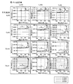
図11は、球形粒子による後方散乱光の散乱強度の角度分布を、Mie散乱理論に基づいて計算した結果を示すものである。ここで、粒子径の平均値は4μm、6μm、10μm、14μm、粒子の屈折率は1.38、1.39、1.4、粒子の周囲の屈折率は1.33である。図11のグラフ中、例えば“E−11”は“×10-11 ”を意味する。他も同じである。
【0036】
図11には、縦横4×3=12個のグラフが示されている。ここで、最上段のグラフの上にある数値は、粒子の上記屈折率である。また、左側のグラフの横(左側)にある数値は、粒子径の上記平均値である。これら数値の横方向と縦方向の各交点に、それぞれの粒子径と屈折率を持つ粒子における、後方散乱光の散乱強度の角度分布の様子を示している。
【0037】
これらのグラフにおいて、 粒子径のばらつきは正規分布に従うとしている。また、平均径が4μmと6μmの粒子については、粒子径の標準偏差を1μmとしている。一方、平均径が10μmと14μmの粒子については、粒子径の標準偏差を1.5μmとしている。そして、各々のグラフにおいて、このような粒子径分布における粒子一個あたりの平均強度を示している。各グラフの横軸の散乱角度は、図12に示すように、入射光101が粒子103に入射したときの散乱光102の方位に対して、図中のθで表される角度として定義される。また、図11のそれぞれのグラフでは、光の波長が400nm、600nm、800nmのときの散乱強度を重ねて表示している。
【0038】
図11において、aの矢印で示すように、波長400nmの光に対して散乱角度175°〜180°の間で散乱強度が極大になることが、各グラフより分かる。また、粒子径が大きい程、その強度ピークが顕著に現れることが分かる。波長400nm、粒子の屈折率が1.39の場合で、粒子径に対して極大値を与える角度をプロットしたのが、図13である。
【0039】
一方、 図11において、bで示すように、散乱角度が175°以下の範囲においては、粒子径、屈折率、波長によらず、散乱角度に対して散乱強度は大きく変化しないことが、各グラフから分かる。また、粒子径が大きくなる程、 aで示した強度ピークのbに対する相対強度が大きくなることが分かる。
【0040】
そこで、例えば、波長400nmの光を球形粒子を含む試料に照射し、試料からの後方散乱光を検出する。試料からの後方散乱光には、単一散乱光と多重散乱光とが含まれる。ここで、単一散乱光は、試料の表面のみにより散乱された光である。一方、多重散乱光は、試料内部に光が拡散して試料内の粒子に多数回散乱された光である。
【0041】
本発明では、例えば、第1の散乱角度範囲を176°〜180°、第2の散乱角度範囲を176°以下と設定し、試料からの後方散乱光をそれぞれの散乱角度範囲で検出する。生体組織内で散乱を繰り返すうちに多重散乱光の角度分布は均一化されるので、第1と第2の散乱角度範囲の近辺で大きく変化しないと考えられる。一方、単一散乱では、第1と第2の散乱角度範囲での相対的な散乱強度の違いが粒子の大きさに応じて生じる。したがって、第1の散乱角度範囲で検出された散乱光の強度と第2の散乱角度範囲で検出された散乱光の強度との差、又は、比を演算することによって、多重散乱光成分は打ち消される。その結果、略単一散乱光成分のみによる散乱信号を抽出することができる。試料中の散乱粒子が大きい程その差あるいは比が大きくなり、粒子の情報が得られる。また、この演算結果を異なる試料間で相対的に比較することにより、 散乱粒子の大きさを判別することができる。
【0042】
また、散乱光を検出する角度範囲は2つの角度に限定することなく、より多くの角度で観測するようにしてもよい。また、波長を変えて観測するようにすることもきる。
【0043】
なお、生体組織の細胞においては、一般に、正常な細胞核で4μm〜7μmの直径を有しており、形成異常の見られる細胞核ではその直径が9μm〜20μm程度に肥大し、それに伴い単位面積当たりに占める細胞核の密度が変化することが知られている。また、後方散乱光は細胞質と該細胞質よりも屈折率の高い細胞核との比屈折率に影響される。細胞質の屈折率1.33に対する細胞核との比屈折率は1.035〜1.05であることが知られている。これらのパラメータを用いることにより、可視波長域の任意の波長光を生体組織の試料面に照射したときに得られる後方散乱角度特性をシミュレーションすることができる。図11の各グラフは、前記パラメータの値の範囲における後方散乱角度特性のシミュレーション結果である。
【0044】
なお、このような観測方法において、光源からの光の波長は500nm以下であることが望ましい。散乱体、特に細胞による後方散乱において、細胞核による散乱を主要な散乱とした場合、図11に示したように、散乱粒子の大きさに対する散乱角度の変化は、光源の波長が短い程顕著である。したがって、特に可視光領域において短波長となる500nm以下の波長を用いることが望ましい。
【0045】
また、波長を変えて観測する場合には、500nm以下の波長と500nm以上の波長を用いることが望ましい。
【0046】
特に、散乱体の粒子の密度に大きなばらつきがある場合には、散乱に寄与する粒子の個数により散乱強度が変化する。そこで、本発明においては、散乱体を照明する光の波長を複数とすることが望ましい。このようにすると、粒子の密度によらず粒子径による散乱信号を得ることができる。図11に示した例においては、波長600nmの光に対する後方散乱強度は、波長500nm以下の光に対する後方散乱強度に比べて、散乱角度による強度の差が非常に小さいことが分かる。そこで、例えば波長600nmでの後方散乱光に対する波長400nmでの後方散乱光の相対強度を、第1の散乱角度範囲と第2の散乱角度範囲のそれぞれについて求める。そして、これらの相対強度を比較することにより、散乱粒子の密度に左右されることなく、粒子の大きさに応じた信号を得ることができることになる。
【0047】
さて、以上のような本発明の原理を実現するための本発明の生体組織の光散乱観測内視鏡装置の1つの実施形態の構成を図1に示す。
【0048】
この生体組織の光散乱観測内視鏡装置は、光源1を備え、その光源1からの照明光は、照明光学系の切換機構5を経て、光ファイバーのような導光体からなる第1の照明光学系2又は同様の第2の照明光学系3へ選択的に導かれる。第1の照明光学系2及び第2の照明光学系3の先端からは照明光が生体組織のような試料Oへ照射される。試料Oで散乱された散乱光は、光ファイバーのような導光体からなる受光光学系4の一端で受光され、その受光光は検出器6へ導かれて検出される。その検出信号は演算装置7へ入力され、第1の照明光学系2で照明したときに受光光学系4を経て検出器6で検出される信号と、第2の照明光学系3で照明したときに受光光学系4を経て検出器6で検出される信号との差又は比がこの演算装置7で演算される。
【0049】
そして、受光光学系4の光軸A0と試料Oの面との交点Pに対して、第1の照明光学系2から入射する照明光の中心光線A1と受光光学系4の光軸A0とのなす角度をα1、第2の照明光学系3から入射する照明光の中心光線A2と受光光学系4の光軸A0とのなす角度をα2とするときに、α1<α2の関係を満足するように、受光光学系4に対して第1の照明光学系2と第2の照明光学系3が配置されている。このとき、前記導光体の開口数が0.3以下であると、受光する後方散乱光の角度を限定できるので、検出時のバックグラウンドノイズを少なくできて好ましい。
【0050】
このように、この生体組織の光散乱観測内視鏡装置の大きな特徴は、1つの検出系(受光光学系4と検出器6)に対して、試料Oの同じ位置Pに異なる角度で照明光を照射する照明系(第1の照明光学系2、第2の照明光学系3)を複数配置して構成した点にある。このような構成をとると、検出系の構成が簡単になるメリットがある。
【0051】
そして、図1の場合、試料Oの面での受光光学系4の受光範囲をd0、第1の照明光学系2による照射範囲をd1、第2の照明光学系3による照射範囲をd2とするとき、受光範囲d0は照射範囲d1、d2何れにも含まれ、かつ、照射範囲d1が照射範囲d2に含まれるように設定することが好ましい。照明光学系2、3をこのように構成することにより、試料Oで散乱される散乱光の角度依存性を観測する前後に、第2の照明光学系3による照明によって試料Oの状態を例えば目視観察することができる。
【0052】
なお、図1においては、照明光学系の切換機構5として、光源1からの光路中へミラー91を挿入して第1の照明光学系2へ反射光を導き、ミラー91を符号91’の位置へ退避させて直接光を第2の照明光学系3へ導くような構成を図示してあるが、これは単なる例示のためであり、光路切り換えのための公知の種々の機構を用いることができる。
【0053】
また、正確な測定を行うためには、第1の照明光学系と第2の照明光学系のそれぞれの照明に対する散乱光の検出強度を補正することが望ましい。
【0054】
まず、試料の測定前に、予め例えば白色拡散板等の基準となる試料の散乱光強度を、第1の照明光学系と第2の照明光学系のそれぞれの照明に対して計測しておく。これをそれぞれR1、R2とする。試料の測定において、第1の照明光学系と第2の照明光学系のそれぞれの照明に対する散乱光強度をS1、S2とする。演算装置では、S1/R1とS2/R2との差又は比を演算することで、2つの照明光学系による照明に大きな強度差が生じるような場合でも正確に測定を行うことができる。
【0055】
また、高いS/Nで観測を行う場合には、測定を複数回又は長時間かけて行う必要がある。ここで試料が生体である場合には、呼吸や拍動等の生体活動に伴う試料の動きがあるため、第1の照明光学系による測定時と第2の照明光学系による測定時では、測定環境や測定条件が異なってしまうことが考えられる。その場合、信号のS/Nが低下し正確な測定が行えない恐れがある。また、光源の出力強度が十分に安定でない場合等においても同様な影響が考えられる。そこで、第1の照明光学系と第2の照明光学系の切り換えを、試料の変動や光源の出力変動に比べ十分に短い時間で繰り返し連続的に行うことで、それらの変動に影響されない測定を行うことができる。また、照明の連続的な切り換えに同期して演算装置による演算を行うことで、それらの変動の影響を受けずに高い時間分解能で観測を行うことができる。
【0056】
図2に、本発明の生体組織の光散乱観測内視鏡装置の別の実施形態の構成を示す。この実施形態は、図1の生体組織の光散乱観測内視鏡装置において、受光光学系4の代わりに対物光学系8を用い、その対物光学系8によって結像される試料Oの像を撮像素子9で撮像するようにした点で異なる。すなわち、光源1を備え、その光源1からの照明光は、照明光学系の切換機構5を経て、光ファイバーのような導光体からなる第1の照明光学系2又は同様の第2の照明光学系3へ選択的に導かれる。第1の照明光学系2及び第2の照明光学系3の先端からは照明光が生体組織のような試料Oへ照射される。試料Oで散乱された散乱光による像は、内視鏡対物レンズのような対物光学系8によって結像され、その散乱像は撮像素子9で撮像される。その撮像された画像信号は演算装置7へ入力され、第1の照明光学系2で照明したときに対物光学系8を経て撮像素子9で撮像された画像信号と、第2の照明光学系3で照明したときに対物光学系8を経て撮像素子9で撮像された画像信号との差又は比がこの演算装置7で演算される。
【0057】
そして、この場合も、対物光学系8の光軸A0と試料Oの面との交点Pに対して、第1の照明光学系2から入射する照明光の中心光線A1と対物光学系8の光軸A0とのなす角度をα1、第2の照明光学系3から入射する照明光の中心光線A2と対物光学系8の光軸A0とのなす角度をα2とするときに、α1<α2の関係を満足するように、対物光学系8に対して第1の照明光学系2と第2の照明光学系3が配置されている。
【0058】
この場合の大きな特徴は、1つの検出系(対物光学系8と撮像素子9とからなる撮像光学系80)に対して、試料Oの同じ位置Pに異なる角度で照明光を照射する照明系(第1の照明光学系2、第2の照明光学系3)を複数配置して構成した点にある。このような構成をとると、例えば内視鏡に組み入れるとき、プローブ先端に配置するCCD等の撮像素子9は1個でよくなり、また、光源1については、内視鏡の外側で光路を分岐しておいて、それをプローブの光ファイバーで導入すればよいので、スペース的に有利となる。
【0059】
図2の場合も、試料Oの面での対物光学系8の受光範囲(撮像範囲)をd0、第1の照明光学系2による照射範囲をd1、第2の照明光学系3による照射範囲をd2とするとき、受光範囲d0は照射範囲d1、d2何れにも含まれ、かつ、照射範囲d1が照射範囲d2に含まれるように設定することが好ましい。照明光学系2、3をこのように構成することにより、試料Oで散乱される散乱光の角度依存性を観測する前後に、第2の照明光学系3による照明によって試料Oの状態を対物光学系8と撮像素子9を介して目視観察することができる。
【0060】
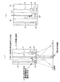
次に、本発明の生体組織の光散乱観測内視鏡装置及び観測方法の実施例を説明する。 図3(a)は第1実施例の生体組織の光散乱観測内視鏡装置の要部の構成を示す図である。この実施例は図1の実施形態に対応する実施例であり、図1の光源1、照明光学系の切換機構5、検出器6、演算装置7に対応する構成は図1の場合と同様であり、図示を省いてある。
【0061】
この実施例において、内視鏡先端部10には、第1の照明光学系2と第2の照明光学系3と受光光学系4が配置され、内視鏡先端部10には先端フード11が取り付けられ、その先端フード11により、試料Oと内視鏡先端部10の距離を一定に保って、散乱光の検出角度θ1、θ2を一定範囲に保っている。
【0062】
そして、第1の照明光学系2は、光ファイバー21とその先端に配置された正レンズ22とからなり、第2の照明光学系3は光ファイバー束31とその先端に配置された負レンズ32とからなり、受光光学系4は光ファイバー41とその先端に配置された正レンズ42とからなり、図1の場合と同様に、試料Oの面での受光光学系4の受光範囲d0は、第1の照明光学系2による照射範囲d1、第2の照明光学系3による照射範囲d2の何れにも含まれ、第1の照明光学系2による照射範囲d1は、第2の照明光学系3による照射範囲d2に含まれるように設定されている。そして、受光光学系の光軸と試料面との交点と第1の照明光学系の射出瞳の中心とを結んだ線分と、受光光学系の光軸とのなす角度をα1、同様に受光光学系の光軸と試料面との交点と第2の照明光学系の射出瞳の中心とを結んだ線分と、受光光学系の光軸とのなす角度をα2としたときにα1<α2の関係を満足するように、受光光学系4に対して第1の照明光学系2と第2の照明光学系3が配置されている。
【0063】
ここで、第1の照明光学系2からの試料Oの面に入射する照明光と受光光学系4で試料Oの面から検出される散乱光とのなす角度を図示のようにθ1とすると、θ1の分布範囲は、図3(b)に示すような範囲となり、そのθ1の分布範囲は176°〜180°の範囲に含まれる。また、第2の照明光学系3からの試料Oの面に入射する照明光と受光光学系4で試料Oの面から検出される散乱光とのなす角度を図示のようにθ2とすると、θ2の分布範囲は、図3(b)に示すような範囲となり、そのθ2の分布範囲は176°以下の範囲に含まれる。そして、第1の照明光学系2、第2の照明光学系3を経て検出器6で検出される受光強度の角度分布は、その配置関係から図3(b)のようになるが、検出器6で検出される実際の受光強度は、照明光学系の切換機構5で第1の照明光学系2に切り換え、第1の照明光学系2で照明した場合は、図3(b)の右側のピークの分布の積分値であり、第2の照明光学系3で照明した場合は、図3(b)の左側のピークの分布の積分値である。その積分値の差又は比を演算装置7で演算することにより、図3(a)に示した後方散乱測定範囲の生体組織の上皮細胞核の大きさを特定することができる。これにより、生体組織の細胞が正常細胞か癌細胞かを区別するための判断材料を、組織を切り取らずに内視鏡的に提供することが可能となる。
【0064】
なお、上記のように、θ1の角度範囲を176°〜180°、θ2の角度範囲を176°以下にすると、細胞核の大きさの判断が最も行いやすくなる。
【0065】
本発明の生体組織の光散乱観測内視鏡装置の第2実施例について、図4を参照にして説明する。図4(a)はこの実施例の要部の構成を示す図である。この実施例も図1の実施形態に対応する実施例であり、図1の光源1、照明光学系の切換機構5、検出器6、演算装置7に対応する構成は図1の場合と同様であり、図示を省いてある。しかし、この実施例においては、第1の照明光学系と受光光学系が1つの光学系によって兼用されており、第1の照明光学系兼受光光学系2’として図示してある。また、この実施例においては、第2の照明光学系と通常観察用照明光学系が1つの光学系によって兼用されており、第2の照明光学系兼通常観察用照明光学系3’として図示してある。内視鏡先端部10には、この第1の照明光学系兼受光光学系2’と第2の照明光学系兼通常観察用照明光学系3’とが配置されおり、第1の照明光学系兼受光光学系2’は、光ファイバー21’とその先端に配置され、全体として正の屈折力を持ったコリメータ光学系22’とからなり、第2の照明光学系兼通常観察用照明光学系3’は、光ファイバー束31’とその先端に配置された負レンズ32’とからなる。
【0066】
第1の照明光学系兼受光光学系2’への光源1からの照明光は、図1の照明光学系の切換機構5と同様の機構により、光ファイバー21’の後端に選択的に導入され、その先端のコリメータ光学系22’でコリメートされた照明光は試料Oへ照射され、試料Oで散乱された散乱光は、同じコリメータ光学系22’で受光されて逆の光路を経て光ファイバー21’の後端に達する。そして、その後端と照明光学系の切換機構5の間に配置されたビームスプリッターや後記の第6実施例のサーキュレータにより照明光から分離され、検出器6へ達するように構成される。
【0067】
内視鏡先端部10には、上記の第1の照明光学系兼受光光学系2’と第2の照明光学系兼通常観察用照明光学系3’の他に、通常観察用の対物光学系15とその像面に配置されたCCDのような撮像素子16とが配置されており、撮像素子16からの画像信号は信号線17を介して不図示の画像処理装置及びモニターに送られ、通常の電子内視鏡の観察装置として使用されるようになっている。
【0068】
この実施例においては、第2の照明光学系兼通常観察用照明光学系3’の照明範囲d2は、通常観察用の対物光学系15と撮像素子16の観察範囲に一致するか又はそれを含むように構成されており、第2の照明光学系兼通常観察用照明光学系3’を経ての照明光の照射により通常観察が行われ、その通常観察によって選択された試料Oの面の測定範囲に、第1の照明光学系兼受光光学系2’からコリメート照明光を照射して、同じ光学系2’を逆に経て第1の散乱角度範囲の測定を行い、第2の照明光学系兼通常観察用照明光学系3’を経て照明光を照射して、第1の照明光学系兼受光光学系2’を逆に経て第2の第1の散乱角度範囲の測定を行うようになっている。このように、この実施例は、通常観察で用いる照明光学系を散乱測定用の一方の照明光学系としても用いるようにしたことにより、構成が簡単になる利点がある。
【0069】
なお、この場合も、試料Oの面での第1の照明光学系兼受光光学系2’の受光範囲d0は、同じ光学系2’による照射範囲d1に含まれ(略同じ)、第2の照明光学系兼通常観察用照明光学系3’による照射範囲d2にも含まれ、第1の照明光学系兼受光光学系2’の照射範囲d1は、第2の照明光学系兼通常観察用照明光学系3’による照射範囲d2に含まれるように設定されている。そして、図1の角度α1とα2がα1<α2の関係を満足するように、第1の照明光学系兼受光光学系2’に対して第2の照明光学系兼通常観察用照明光学系3’が配置されており、また、散乱光の検出角度θ1、θ2を、θ1が176°〜180°、θ2が176°以下の範囲になるようにしている。
【0070】
図4(b)は、図4(a)の第2実施例の変形例の要部の構成を示す図4(a)と同様の図であり、変形部分は、第1の照明光学系兼受光光学系2’をプローブとして従来の内視鏡の鉗子チャンネル18に挿入、取り外し可能に構成し、散乱測定時にのみ鉗子チャンネル18に挿入して使用するようにした点であり、その他の構成、使用方法は図4(a)の場合と同様である。
【0071】
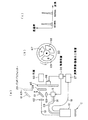
図5(a)は第3実施例の生体組織の光散乱観測内視鏡装置の要部の構成を示す図であり、図5(b)はその内視鏡先端部10の正面図である。この実施例は図2の実施形態に対応する実施例であり、図2の照明光学系の切換機構5、演算装置7に対応する構成は図2の場合と同様であり、図示を省略している。また、光源1は、図14に示すように、光源ランプ101と、照明光学系の切換機構5に導くための光学系102と、これらの光路中に挿脱自在に配置される複数の波長選択フィルター103、104と、図示しない光量調整絞りとからなり、複数の波長選択フィルター103、104の組み合わせを変えることによって、少なくとも生体組織の試料面の光散乱観測に用いる可視波長領域の狭いバンド照明光を生成するモードと、生体組織の試料面及びその周辺の様子を観察するために用いる青色(B)、緑色(G)、赤色(R)の順次照明光を生成するモード若しくは白色照明光を生成するモードに切換可能に構成されている。
【0072】
例えば、生体組織の試料面の光散乱観測に用いる可視波長領域の狭いバンド照明光を生成するモードの場合、図15(a)及び(c)〜(e)に波長特性を示すフィルターを組み合わせる。図15(a)のフィルターは、光源1の光束中に固定して半値幅で10nm〜30nmの極狭いバンド光を選択的に透過する。図15(c)〜(e)のフィルターは、光源1の光束中に間欠的に挿入され、図15(a)のフィルターを透過した光をさら選択して透過する。このようにして、生体組織の試料面の光散乱観測に用いる可視波長領域の狭いバンド照明光が生成する。
【0073】
生体組織の試料面及びその周辺の様子を観察するために用いる青色(B)、緑色(G)、赤色(R)の順次照明光を生成するモードの場合、図15(b)及び(c)〜(e)に示すフィルターを組み合わせる。図15(b)のフィルターは、光源1の光束中に固定して可視波長域の光を選択的に透過する。図15(c)〜(e)のフィルターは光源1の光束中に間欠的に挿入され、青色(B)、緑色(G)、赤色(R)の順次照明光を生成する。
【0074】
白色照明光を生成するモードの場合、図15(b)に示すフィルターのみが光源1の光束中に挿入される。
【0075】
この実施例において、内視鏡先端部10には、第1の照明光学系2と、第2の照明光学系3と、対物光学系8及びその対物光学系8によって結像される像を撮像する撮像素子9からなる撮像光学系80とが配置され、さらに、光ファイバー束51とその先端に配置された拡散光学系52とからなる通常観察用照明光学系50が別に配置されている。
【0076】
この例では、第1の照明光学系2は、対物光学系8と撮像素子9とからなる撮像光学系80の周囲に配置された光ファイバー束23からなり、第2の照明光学系3は光ファイバー束31とその先端に配置された負レンズ32とからなり、試料Oの面での対物光学系8の撮像範囲d0は、第1の照明光学系2による照射範囲d1、第2の照明光学系3による照射範囲d2何れにも含まれ、かつ、照射範囲d1が照射範囲d2に含まれるように設定されており、かつ、通常観察用照明光学系50による照射範囲は、第2の照明光学系3による照射範囲d2以上に設定されている。
【0077】
この例では、対物光学系8と撮像素子9とからなる撮像光学系80は、通常観察用の光学系と後方散乱測定用の光学系とを兼ねており、次のような手順により観察が行われる。まず、体腔内に内視鏡を挿入し、通常観察用照明光学系50より青色(B)、緑色(G)、赤色(R)の時分割照明光若しくは白色照明光を照射して、モニター上に映った通常カラー画像を観察しながら内視鏡先端部を観察部位まで誘導する。次に、観察部位に内視鏡先端部を近接させて、モニターに映った通常カラー画像の中心に試料面Oが位置するように内視鏡先端部の位置を調整する。次に、光源の照明モードを切り換えて、第1の照明光学系2より500nm以下の狭いバンド光を一定時間照射すると共に、試料面Oからの後方散乱光による像を対物光学系8と撮像素子9により撮像し、画像信号Q1を得る。次に、第2の照明光学系3より前記500nm以下の狭いバンド光を一定時間照射すると共に、試料面Oからの後方散乱光による像を対物光学系8と撮像素子9により撮像し、画像信号Q2を得る。これらの画像信号は信号線19を介して演算装置7(図2)へ送られ、画像信号Q1と画像信号Q2の差又は比の演算が行われる。上記のように、モニター上の画像中心に試料面Oが位置するように内視鏡先端部の位置を調整することにより、対物光学系8の持つ諸収差の影響をほとんど受けずに試料面Oからの後方散乱光を観測することができる。
【0078】
この実施例は、このように、通常観察専用の照明光学系50と散乱測定専用の照明光学系2、3とを別に設けるようにしたことにより、それぞれ最も最適な状態で観察又は観測(測定)できる利点がある。
【0079】
この場合も、図2の角度α1とα2がα1<α2の関係を満足するように、対物光学系8に対して第1の照明光学系2と第2の照明光学系3が配置されており、また、散乱光の検出角度θ1、θ2を、θ1が176°〜180°、θ2が176°以下の範囲になるように設定されている。
【0080】
図6(a)は第4実施例の生体組織の光散乱観測内視鏡装置の全体の構成を示す図であり、この実施例の内視鏡先端部10には図5(a)の第3実施例のものを用いている。
【0081】
この実施例においては、白色光源60を用い、その前面にR(赤色)波長域透過フィルター67、G(緑色)波長域透過フィルター68、B(青色)波長域透過フィルター69がセクター状に配置されてなる図6(b)のようなRGBホイール65が配置されており、RGBホイール65はモータ66によって回転制御されている。そのため、RGBホイール65のRGBの何れかの波長域透過フィルターを順に透過したRGBと変わる光は、挿脱可能なバンドパスフィルター29とミラー61に達し、バンドパスフィルター29とミラー61が光路から離脱されている場合(図の破線)は、集光レンズ62により集光されて、図5(a)の通常観察用照明光学系50の光ファイバー束51の後端に集光される。光ファイバー束51に入射したRGBと順に変化する照明光は、通常観察用照明光学系50の先端の拡散光学系52により発散光となって試料Oを照明し、そのRGBと順に変化する照明光により、対物光学系8はRGB面順次で試料Oの像を撮像素子9上に結像し(図5(a))、撮像素子9で撮像されたRGB面順次の画像信号は信号線19を介して演算装置・画像出力装置27へ送られ、試料Oのカラー画像を表示装置に出力する。
【0082】
ここで、バンドパスフィルター29の透過波長は、図6(c)に示すように、例えばR波長域の波長600nmとB波長域の波長400nmに透過帯域を持つバンドパスフィルターであり、バンドパスフィルター29とミラー61が光路に挿入されると(図の実線)、RGBホイール65が回転されてB波長域透過フィルター69が光路中にある期間には、バンドパスフィルター29により波長400nmを中心とする狭帯域の光が集光レンズ63に達して、その集光レンズ63によって照明光学系の切換機構5の入力端に集光される。照明光学系の切換機構5では、B波長域透過フィルター69が光路中にある期間内に、その波長400nmを中心とする狭帯域の照明光を、第1の照明光学系2の光ファイバー束23の後端に入射させる期間と、第2の照明光学系3の光ファイバー束31の後端に入射させる期間とに切り換える。第1の照明光学系2がその波長400nmを中心とする狭帯域の照明光を照射している間に、対物光学系8と撮像素子9(図5(a))により、第1の散乱角度範囲での試料Oの散乱像の撮像を行い、第2の照明光学系3がその波長400nmを中心とする狭帯域の照明光を照射している間に、その対物光学系8と撮像素子9により、第2の散乱角度範囲での試料Oの散乱像の撮像を行い、それらの画像信号は信号線19を介して演算装置・画像出力装置27へ送られる。
【0083】
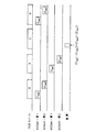
その様子は図7のタイミングチャートに図示されており、RGBホイール65のB波長域透過フィルター69が光路中にある期間に、波長400nmで第1の散乱角度範囲での散乱像の撮像と、第2の散乱角度範囲での散乱像の撮像とを行う。図中に、波長400nmで第1の散乱角度範囲での散乱像の撮像を(1400 )、第2の散乱角度範囲での散乱像の撮像を(2400 )として示してある。
【0084】
次に、RGBホイール65が回転されてR波長域透過フィルター67が光路中にある期間には、バンドパスフィルター29により波長600nmを中心とする狭帯域の光が集光レンズ63に達して、照明光学系の切換機構5により第1の照明光学系2の光ファイバー束23の後端に入射させる期間と、第2の照明光学系3の光ファイバー束31の後端に入射させる期間とに切り換える。第1の照明光学系2がその波長600nmを中心とする狭帯域の照明光を照射している間に、対物光学系8と撮像素子9により、第1の散乱角度範囲での試料Oの散乱像の撮像である撮像(1600 )を行い、第2の照明光学系3がその波長600nmを中心とする狭帯域の照明光を照射している間に、第2の散乱角度範囲での試料Oの散乱像の撮像である撮像(2600 )を行い、それらの画像信号は信号線19を介して演算装置・画像出力装置27へ送られる。
【0085】
その次の、RGBホイール65が回転されてG波長域透過フィルター68が光路中にある期間には、光源60からの光はバンドパスフィルター29でブロックされ、第1の照明光学系2、第2の照明光学系3には達せず、この間に上記の{(1400 )−(2400 )}÷{(1600 )−(2600 )}の演算が演算装置・画像出力装置27で行われ、前記したように、散乱粒子の密度に左右されることなく、粒子の大きさに応じた信号を得ることができる。
【0086】
なお、図7に示したような撮像のタイミングと演算のタイミングは、図6(a)の制御装置28によって、モータ66の回転角、照明光学系の切換機構5の切り換え、演算装置・画像出力装置27の画像信号取り込み、演算を同期して制御することにより行われる。
【0087】
この実施例は、通常観察用照明光学系50と対物光学系8及び撮像素子9とを用いた試料Oの通常観察に用いられる面順次フィルターであるRGBホイール65を散乱計測での波長切り換えにも用いる例であり、装置が単純化される利点がある。
【0088】
次に、本発明の第5実施例の生体組織の光散乱観測内視鏡装置を図8に示す。図8(a)は内視鏡100の内視鏡先端部10の正面図であり、図8(b)は全体の構成を示すブロック図である。この実施例においては、図8(a)に示すように、内視鏡先端部10の略中心に配置した単一の受光光学系4又は撮像光学系80の周りに、第1の照明光学系2として、例えば波長400nmの光を発光する青色LED2B と、波長600nmの光を発光する赤色LED2R とを、所定距離離れた試料Oの面からの散乱光の受光光学系4又は撮像光学系80への入射角度範囲が176°〜180°に含まれることになる位置に取り付け、また、第2の照明光学系3として、例えば波長400nmの光を発光する青色LED3B と、波長600nmの光を発光する赤色LED3R とを、所定距離離れた試料Oの面からの散乱光の受光光学系4又は撮像光学系80への入射角度範囲が176°以下に含まれることになる位置に取り付けて構成されるものである。受光光学系4と撮像光学系80は、第1実施例〜第4実施例で説明したのと同様のものを用いている。なお、この場合に、受光光学系4又は撮像光学系80の受光範囲(撮像範囲)d0は、第1の照明光学系2B と2R の照射範囲d1、及び、第2の照明光学系3B と3R の照射範囲d2の何れにも含まれていればよい。
【0089】
このような配置であるので、制御装置28は、例えば、順に、青色LED2B 、青色LED3B 、赤色LED2R 、赤色LED3R を点灯して、それらの照明に基づいて信号(1400 )、(2400 )、(1600 )、(2600 )を検出し、演算装置7で、図6〜図7の場合と同様に、{(1400 )−(2400 )}÷{(1600 )−(2600 )}の演算を行うようにして、散乱粒子の密度に左右されることなく、粒子の大きさに応じた信号を得ることができる。
【0090】
この実施例は、内視鏡先端部10に照明用のLED2B 、2R 、3B 、3R を配置することで、照明の切り換えを外部から電気的に行えばよくなり、構成が簡単になる利点がある。
【0091】
次に、本発明の第6実施例の生体組織の光散乱観測内視鏡装置の構成を示す図を図9に示す。この実施例は、レーザースキャンプローブを用いて散乱像を画像化する例である。この実施例においては、第1の照明光学系と受光光学系が1つの光学系によって兼用されており、第1の照明光学系兼受光光学系2’として図示してある。そして、この第1の照明光学系兼受光光学系2’は、光ファイバー21’と、その先端に配置されたコリメータ光学系22’と、コリメータ光学系22’でコリメートされた照明光を2次元方向に走査する走査装置24’とからなり、第2の照明光学系3は、光ファイバー束31とその先端に配置された負レンズ32とからなる。
【0092】
この実施例においては、例えば波長400nmのレーザー1’から発振されたレーザー光は、光路切換装置5’を経て、第1の照明光学系兼受光光学系2’と第2の照明光学系3へ選択的に向けられる。第1の照明光学系兼受光光学系2’へ向けられた照明光は、サーキュレータ71を経て光ファイバー21’の後端に導入され、その先端のコリメータ光学系22’でコリメートされ、走査装置24’によりり試料Oの面を走査するように照射され、試料Oで散乱された散乱光は、同じ走査装置24’とコリメータ光学系22’との逆の光路を経て光ファイバー21’の後端に達する。そして、その後端に配置されたサーキュレータ71を介して照明光から分離され、検出器6へ達して検出される。
【0093】
この検出信号を走査装置24’の走査位置と同期させて表示することにより、試料Oの面の散乱像を画像出力装置70に表示するようにすることもできると共に、演算装置7で第1の照明光学系兼受光光学系2’を経て照明したときに検出される信号と、第2の照明光学系3を経て照明したときに検出される信号との差又は比を演算することにより、散乱像の差又は比の画像を得ることもできる。
【0094】
この実施例によれば、走査装置24’の走査範囲を制御することにより、あるいは、得られた画像領域を切り出すことにより、注目したい領域だけの差あるいは比の信号又は画像を得ることもできる。
【0095】
また、この実施例を変形して、第2実施例の変形例(図4(b))と同様に、第1の照明光学系兼受光光学系2’をプローブとして従来の内視鏡の鉗子チャンネルに挿入、取り外し可能に構成し、散乱測定時にのみ鉗子チャンネルに挿入して使用するようにすることもできる。
【0096】
ところで、以上の実施例の説明から明らかなように、本発明の生体組織の光散乱観測内視鏡装置を内視鏡先端部に組み込んで構成する場合に、通常観察用照明光学系と散乱測定用の照明光学系、特に、第2の照明光学系を独立に配置したり兼用させるようにすることができること、さらには、通常観察用の対物光学系と散乱測定用の受光光学系あるいは撮像光学系を独立に配置したり兼用させるようにすることができる。そこで、図10(a)〜(b)にそれぞれの配置例を示す。図中、符号2は独立した散乱測定用の第1の照明光学系、3は独立した散乱測定用の第2の照明光学系、4は独立した散乱測定用の受光光学系、50は独立した通常観察用照明光学系、15は独立した通常観察用の対物光学系、3’は第2の照明光学系兼通常観察用照明光学系、15’は通常観察用の対物光学系と散乱測定用の受光光学系又は撮像光学系の兼用光学系である。したがって、図10(a)は、通常観察用照明光学系50と散乱測定用の第1の照明光学系2及び第2の照明光学系3を独立に配置し、かつ、通常観察用の対物光学系15と散乱測定用の受光光学系4を独立に配置した内視鏡先端部10の正面図であり、図10(b)は、通常観察用照明光学系と散乱測定用の第2の照明光学系を兼用させて第2の照明光学系兼通常観察用照明光学系3’とし、通常観察用の対物光学系15と散乱測定用の受光光学系4を独立に配置した内視鏡先端部10の正面図であり、図10(c)は、通常観察用照明光学系50と散乱測定用の第1の照明光学系2及び第2の照明光学系3を独立に配置し、かつ、通常観察用の対物光学系と散乱測定用の撮像光学系を兼用させて兼用光学系15’として配置した内視鏡先端部10の正面図であり、図10(d)は、通常観察用照明光学系と散乱測定用の第2の照明光学系を兼用させて第2の照明光学系兼通常観察用照明光学系3’とし、また、通常観察用の対物光学系と散乱測定用の撮像光学系を兼用させて兼用光学系15’として配置した内視鏡先端部10の正面図である。
【0097】
以上、本発明の生体組織の光散乱観測内視鏡装置及び観測方法をその原理と実施形態、実施例に基づいて説明してきたが、本発明はこれらの実施形態、実施例に限定されず種々の変形が可能である。
【0098】
【発明の効果】
以上の説明から明らかなように、本発明の生体組織の光散乱観測内視鏡装置及び観測方法によると、例えば内視鏡で散乱スペクトル情報を画像として観測する場合に、内視鏡先端部を小型化でき、また、検出光学系を簡素化できる。
【図面の簡単な説明】
【図1】本発明の生体組織の光散乱観測内視鏡装置の1つの実施形態の構成を示す図である。
【図2】本発明の生体組織の光散乱観測内視鏡装置の別の実施形態の構成を示す図である。
【図3】第1実施例の生体組織の光散乱観測内視鏡装置の要部の構成と検出される各照明光学系からの照明光の散乱角度分布を示す図である。
【図4】第2実施例の生体組織の光散乱観測内視鏡装置の要部の構成とその変形例の要部の構成を示す図である。
【図5】第3実施例の生体組織の光散乱観測内視鏡装置の要部の構成とその内視鏡先端部の正面を示す図である。
【図6】第4実施例の生体組織の光散乱観測内視鏡装置の構成と作用を説明するための図である。
【図7】第4実施例の生体組織の光散乱観測内視鏡装置の動作を示すタイミングチャートである。
【図8】第5実施例の生体組織の光散乱観測内視鏡装置の内視鏡先端部の正面図と全体の構成を示すブロック図である。
【図9】第6実施例の生体組織の光散乱観測内視鏡装置の構成を示す図である。
【図10】本発明の生体組織の光散乱観測内視鏡装置を内視鏡先端部に組み込んで構成する場合の配置例を示す図である。
【図11】球形粒子による後方散乱光の散乱強度の角度分布をMie散乱理論により計算した結果を示す図である。
【図12】散乱角度の定義を示す図である。
【図13】粒子径に対して極大値を与える角度をプロットした図である。
【図14】第3実施例に用いられる光源の詳細な構成を示した図である。
【図15】第3実施例に用いられる光源の光路中に配置される波長選択フィルターの透過特性を示した図である。
【符号の説明】
O…試料
1…光源
1’…レーザー
2…第1の照明光学系
2’…第1の照明光学系兼受光光学系
2B …青色LED
2R …赤色LED
3…第2の照明光学系
3’…第2の照明光学系兼通常観察用照明光学系
3B …青色LED
3R …赤色LED
4…受光光学系
5…照明光学系の切換機構
5’…光路切換装置
6…検出器
7…演算装置
8…対物光学系
9…撮像素子
10…内視鏡先端部
11…先端フード
15…通常観察用の対物光学系
15’…通常観察用の対物光学系と散乱測定用の受光光学系又は撮像光学系の兼用光学系
16…撮像素子
17…信号線
18…鉗子チャンネル
19…信号線
21…光ファイバー
21’…光ファイバー
22…正レンズ
22’…コリメータ光学系
23…光ファイバー束
24’…走査装置
27…演算装置・画像出力装置
28…制御装置
29…バンドパスフィルター
31…光ファイバー束
31’…光ファイバー束
32…負レンズ
32’…負レンズ
41…光ファイバー
42…正レンズ
50…通常観察用照明光学系
51…光ファイバー束
52…拡散光学系
60…白色光源
61…ミラー
62…集光レンズ
63…集光レンズ
65…RGBホイール
66…モータ
67…R(赤色)波長域透過フィルター
68…G(緑色)波長域透過フィルター
69…B(青色)波長域透過フィルター
70…画像出力装置
71…サーキュレータ
80…撮像光学系
91、91’…ミラー
100…内視鏡
101…光源ランプ
102…光学系
103、104…波長選択フィルター[0001]
BACKGROUND OF THE INVENTION
The present invention relates to a light scattering observation endoscope apparatus and observation method for living tissue, and more particularly to an apparatus and method for observing the state of a tissue by observing backscattered light from the living tissue.
[0002]
[Prior art]
A technique for observing cell information on a living tissue by detecting scattered light when the living tissue is irradiated with light is known. For example,
[0003]
The outline will be described. Light is incident on a living tissue, and scattered light at that time is detected and dispersed (detection of a scattered spectrum). Information (particle diameter, refractive index, etc.) of the scattering particles can be known from the scattering spectrum. On the other hand, when normal cells and cancer cells are compared, it is known that cancer cells have larger nuclei. Therefore, by observing the scattering spectrum from the biological tissue, the information on the size of the nucleus (scattering particles) can be obtained, and therefore it can be determined whether the observed portion is normal or cancerous.
[0004]
However, the scattered light from the living tissue contains both single scattering (single scattering) and multiple scattering components. Since particle information is contained in a single scattering component, it is necessary to remove multiple scattering components. As a method for this, scattered light is detected at a plurality of angles, and the scattered light intensity between the angles is calculated.
[0005]
[Patent Document 1]
Japanese translation of PCT publication No. 2002-535645 (WO00 / 43750)
[0006]
[Problems to be solved by the invention]
In this conventional example, an example using one illumination optical system and a plurality of detection optical systems is shown as a specific configuration for detecting at a plurality of angles. When there are a plurality of detection optical systems, the size of the distal end portion of the endoscope increases, particularly when the scattered spectrum information is observed as an image with an endoscope. Moreover, the structure will also become complicated.
[0007]
The present invention has been made in view of such problems of the prior art, the purpose of which, for example, when observing scattered spectrum information as an image with an endoscope, the tip of the endoscope can be miniaturized, It is another object of the present invention to provide a light scattering observation endoscope apparatus and observation method for living tissue that can simplify a detection optical system.
[0008]
[Means for Solving the Problems]
An endoscope apparatus for light scattering observation of a living tissue according to the first aspect of the present invention that achieves the above object includes a first illuminating means and a second illuminating means that illuminate a sample surface of the living tissue, and a sample surface of the living tissue. A light receiving means for receiving the scattered light, a detector for detecting the light received by the light receiving means, a signal detected when illuminated by the first illumination means, and a detection by the second illumination means And calculating means for calculating the difference or ratio with the signal when
An angle formed by the central ray of the illumination light incident from the first illumination unit and the optical axis of the light receiving unit with respect to the intersection of the optical axis of the light receiving unit and the sample surface of the living tissue is α1, When α2 is an angle formed by the central ray of the illumination light incident from the second illumination unit and the optical axis of the light receiving unit with respect to the intersection of the optical axis and the sample surface of the living tissue, α1 <α2 The first illuminating unit and the second illuminating unit are arranged with respect to the light receiving unit so as to satisfy the relationship.
[0009]
In this case, the illumination range by the first illumination unit on the sample surface of the biological tissue includes the light reception range of the light receiving unit, and the illumination range by the second illumination unit is the illumination range by the first illumination unit. It is desirable that the first illumination unit and the second illumination unit are arranged with respect to the light receiving unit so as to include
[0010]
The angle formed between the illumination light incident on the sample surface of the biological tissue when illuminated by the first illumination unit and the scattered light detected from the sample surface of the biological tissue by the light receiving unit is 176 ° to 180 °. The angle between the illumination light included in the range and incident on the sample surface of the biological tissue when illuminated by the second illumination means and the scattered light detected from the sample surface of the biological tissue by the light receiving means is 176 ° or less. It is desirable that the first illuminating unit and the second illuminating unit are arranged with respect to the light receiving unit so as to be included in the range.
[0011]
In addition, it is desirable to separately include an objective optical system for observing the sample surface of the living tissue and an image sensor disposed on the image plane.
[0012]
The first illuminating unit and the light receiving unit are configured to share at least a part of an optical axis, and the first illuminating unit and the light receiving unit include a sample surface of the living tissue, the second light receiving unit, The space between the illumination means may be configured to be movable.
[0013]
The second illumination means can also serve as an illumination means for observing the sample surface of the living tissue.
[0014]
Furthermore, a light source and a mechanism for continuously switching and guiding the light from the light source to one of the first illumination unit and the second illumination unit may be provided.
[0015]
Further, it is desirable that the illumination light from the first illumination unit and the second illumination unit is light of 500 nm or less.
[0016]
Further, any two narrow band lights in the visible wavelength region may be used as illumination light from the first illumination means and the second illumination means, and the calculation by the calculation means may be performed by switching wavelengths. it can.
[0017]
In this case, the difference between the signal detected when illuminated by the first illumination means using a narrow band light having a wavelength of 500 nm or less and the signal detected when illuminated by the second illumination means is calculated. Difference between a signal detected when illuminated by the first illumination means using a narrow band light having a wavelength of 500 nm or more as a difference signal I and a signal detected when illuminated by the second illumination means Is the difference signal II, it is desirable to calculate the difference or ratio between the difference signals I and II by the calculating means.
[0018]
The light receiving means may include a collimator optical system.
[0019]
The first illumination unit and the light receiving unit may be configured by the same collimator optical system.
[0020]
The first illumination unit and the second illumination unit may include an LED.
[0021]
The second biological tissue light scattering observation endoscope apparatus of the present invention receives first and second illumination means for illuminating the sample surface of the biological tissue, and scattered light from the sample surface of the biological tissue. An objective optical system, an imaging element that captures an image of a sample surface of a biological tissue imaged by the objective optical system, an image captured when illuminated by the first illumination means, and the second illumination Calculating means for calculating the difference or ratio with the image taken by the means,
The angle formed by the central ray of the illumination light incident from the first illumination means and the optical axis of the objective optical system with respect to the intersection of the optical axis of the objective optical system and the sample surface of the living tissue is α1, and the objective When the angle between the central ray of the illumination light incident from the second illumination means and the optical axis of the objective optical system with respect to the intersection of the optical axis of the optical system and the sample surface of the biological tissue is α2, Satisfying the relationship of α1 <α2,
Furthermore, the angle formed between the illumination light incident on the sample surface of the biological tissue when illuminated by the first illumination means and the scattered light received from the sample surface of the biological tissue by the objective optical system is 176 ° to 180 ° The angle between the illumination light included in the range and incident on the sample surface of the biological tissue when illuminated by the second illumination means and the scattered light received from the sample surface of the biological tissue by the objective optical system is 176 ° or less. The first illuminating unit and the second illuminating unit are arranged with respect to the objective optical system so as to be included in the range.
[0022]
In this case, it is desirable that the illumination light from the first illumination unit and the second illumination unit is light of 500 nm or less.
[0023]
The illumination range by the first illumination unit on the sample surface of the biological tissue includes the light receiving range of the objective optical system, and the illumination range by the second illumination unit is the illumination range by the first illumination unit. It is desirable that the first illumination unit and the second illumination unit are arranged with respect to the objective optical system so as to include
[0024]
Further, the second illuminating means can also serve as the illuminating means for observing the state of the sample surface of the living tissue and its surroundings.
[0025]
In addition, it has a light source in which a plurality of wavelength selection filters are detachably arranged in the optical path,
The light source includes at least a mode for generating a band illumination light having a narrow visible wavelength region used for light scattering observation of the sample surface of the biological tissue, and a blue color (B) used for observing the sample surface of the biological tissue and its surroundings. , Green (G), red (R) sequential illumination light generation mode or white illumination light generation mode.
[0026]
In addition, a plurality of wavelength selection filters are detachably arranged in the optical path in the light source, and a band having a narrow visible wavelength region used for light scattering observation of a sample surface of a biological tissue can be obtained by changing the combination of the wavelength selection filters. A mode for generating illumination light and a mode for generating sequential illumination light of blue (B), green (G), and red (R) used for observing the sample surface of the biological tissue and its surroundings, or white illumination light It may be configured to be switchable to a mode for generating.
[0027]
The endoscope apparatus for light scattering observation of a biological tissue according to a third aspect of the present invention receives first and second illumination means for illuminating the sample surface of the biological tissue, and scattered light from the sample surface of the biological tissue. An objective optical system, an imaging element that captures an image of a sample surface of a biological tissue imaged by the objective optical system, an image captured when illuminated by the first illumination means, and the second illumination Calculating means for calculating the difference or ratio with the image taken by the means,
The angle formed by the central ray of the illumination light incident from the first illumination means and the optical axis of the objective optical system with respect to the intersection of the optical axis of the objective optical system and the sample surface of the living tissue is α1, and the objective When the angle between the central ray of the illumination light incident from the second illumination means and the optical axis of the objective optical system with respect to the intersection of the optical axis of the optical system and the sample surface of the biological tissue is α2, The first illuminating means and the second illuminating means are arranged with respect to the objective optical system so as to satisfy the relationship of α1 <α2, and the illuminating device is used for light scattering observation of a sample surface of a living tissue. The illumination light emitted from the first illumination means and the second illumination means at intervals of time is narrow band light of 500 nm or less.
[0028]
The biological tissue light scattering observation method of the present invention includes a light receiving means having a light receiving window at least at a tip portion, a first illuminating means having a first illumination window, and a second illuminating means having a second illumination window. In the method of observing light scattering on the sample surface of the biological tissue by inserting the insertion portion into the body cavity,
An arbitrary narrow band light in the visible wavelength region is irradiated for a certain time from the first illumination window arranged closest to the light receiving window toward the sample surface of the living tissue, and from the sample surface of the living tissue through the light receiving window. A first step of receiving the scattered light of
Irradiating with an arbitrary narrow band light in the visible wavelength region for a certain time from the second illumination window toward the sample surface of the biological tissue shifted from the illumination time from the first illumination window, and through the light receiving window, the biological tissue A second step of receiving scattered light from the sample surface of
The method includes a third step of calculating a difference or ratio between the scattered light intensity received in the first step and the scattered light intensity received in the second step.
[0029]
In this case, it is desirable that the arbitrarily narrow band light in the visible wavelength region is a narrow band light of 500 nm or less.
[0030]
Further, a fourth light beam is irradiated from the first illumination window toward the sample surface of the living tissue while receiving scattered light from the sample surface of the living tissue through the light receiving window. And the steps
Illuminating another narrow band light in the visible wavelength region from the second illumination window toward the sample surface of the biological tissue for a certain period of time shifted from the illumination time from the first illumination window, and living tissue through the light receiving window. A fifth step for receiving the scattered light from the sample surface, and a sixth step for calculating a difference or ratio between the scattered light intensity received in the fourth step and the scattered light intensity received in the fifth step. Steps,
A seventh step of calculating the difference or ratio between the calculation results obtained in the third step and the sixth step may be included.
[0031]
DETAILED DESCRIPTION OF THE INVENTION
First, the principle of observing the state of cells in the present invention will be described.
[0032]
Information (particle diameter, refractive index, etc.) of the scattering particles can be measured from the scattering spectrum. For example, cancer cells and normal cells have different cell nuclei diameters, so that normal cells and cancer cells can be distinguished (diagnosed) by measuring a scattering spectrum. According to such an observation, normal cells and cancer cells can be distinguished from each other in a non-invasive manner and with a relatively simple configuration (by simply irradiating and spectralizing ordinary light).
[0033]
However, the living body is a multiple scatterer. In order to obtain information on particles (cell nuclei), it is necessary to measure the scattering of only the particles (single scattering), but the return light when light is applied to the living body is single scattering + multiple scattering (inside the living body). Scattered light coming out deeply). The multiple scattering component is an accumulation of scattering by a plurality of particles, and becomes a noise component. In addition, the multiple scattering component occupies most of the return light.
[0034]
Therefore, it is necessary to remove the multiple scattering components from the return light and extract only a single scattering component.
[0035]
FIG. 11 shows the result of calculating the angular distribution of the scattering intensity of the backscattered light by the spherical particles based on the Mie scattering theory. Here, the average value of the particle diameter is 4 μm, 6 μm, 10 μm, and 14 μm, the refractive indexes of the particles are 1.38, 1.39, and 1.4, and the refractive index around the particles is 1.33. In the graph of FIG. 11, for example, “E-11” is “× 10”. -11 ”Means the same.
[0036]
FIG. 11 shows vertical and horizontal 4 × 3 = 12 graphs. Here, the numerical value on the uppermost graph is the refractive index of the particle. The numerical value on the side (left side) of the left graph is the average value of the particle diameters. At each intersection of these numerical values in the horizontal direction and the vertical direction, the state of the angular distribution of the backscattered light scattering intensity in the particles having the respective particle diameter and refractive index is shown.
[0037]
In these graphs, the particle size variation follows a normal distribution. In addition, for particles having an average diameter of 4 μm and 6 μm, the standard deviation of the particle diameter is 1 μm. On the other hand, for particles having an average diameter of 10 μm and 14 μm, the standard deviation of the particle diameter is 1.5 μm. In each graph, the average intensity per particle in such a particle size distribution is shown. As shown in FIG. 12, the scattering angle on the horizontal axis of each graph is defined as an angle represented by θ in the figure with respect to the orientation of the
[0038]
In FIG. 11, it can be seen from each graph that the scattering intensity becomes maximum between scattering angles of 175 ° and 180 ° with respect to light having a wavelength of 400 nm, as indicated by an arrow a. Moreover, it turns out that the intensity | strength peak appears notably, so that a particle diameter is large. FIG. 13 is a plot of the angle giving the maximum value with respect to the particle diameter when the wavelength is 400 nm and the refractive index of the particle is 1.39.
[0039]
On the other hand, as shown by b in FIG. 11, in the range where the scattering angle is 175 ° or less, the scattering intensity does not change greatly with respect to the scattering angle regardless of the particle diameter, the refractive index, and the wavelength. I understand. Moreover, it turns out that the relative intensity | strength with respect to b of the intensity | strength peak shown by a becomes large, so that a particle diameter becomes large.
[0040]
Therefore, for example, a sample including spherical particles is irradiated with light having a wavelength of 400 nm, and backscattered light from the sample is detected. The backscattered light from the sample includes single scattered light and multiple scattered light. Here, the single scattered light is light scattered only by the surface of the sample. On the other hand, the multiple scattered light is light that is diffused many times by particles in the sample as the light diffuses inside the sample.
[0041]
In the present invention, for example, the first scattering angle range is set to 176 ° to 180 °, the second scattering angle range is set to 176 ° or less, and the back scattered light from the sample is detected in each scattering angle range. As the angular distribution of the multiple scattered light becomes uniform as the scattering is repeated in the living tissue, it is considered that there is no significant change in the vicinity of the first and second scattering angle ranges. On the other hand, in single scattering, a difference in relative scattering intensity between the first and second scattering angle ranges occurs according to the size of the particle. Therefore, the multiple scattered light component is canceled by calculating the difference or ratio between the intensity of the scattered light detected in the first scattering angle range and the intensity of the scattered light detected in the second scattering angle range. It is. As a result, it is possible to extract a scattered signal based on only a substantially single scattered light component. The larger the scattering particles in the sample, the larger the difference or ratio, and the particle information can be obtained. Moreover, the size of the scattering particles can be determined by relatively comparing the calculation results between different samples.
[0042]
Further, the angle range for detecting scattered light is not limited to two angles, and observation may be performed at more angles. It is also possible to observe with different wavelengths.
[0043]
In general, cells in living tissue have a diameter of 4 μm to 7 μm in normal cell nuclei, and in cell nuclei with dysplasia, the diameter is enlarged to about 9 μm to 20 μm, and accordingly, per unit area. It is known that the density of the occupied cell nucleus changes. Further, the backscattered light is affected by the relative refractive index between the cytoplasm and a cell nucleus having a higher refractive index than the cytoplasm. It is known that the relative refractive index of the cell nucleus with respect to the refractive index of the cytoplasm of 1.33 is 1.035 to 1.05. By using these parameters, it is possible to simulate the backscattering angle characteristics obtained when the sample surface of the living tissue is irradiated with light having an arbitrary wavelength in the visible wavelength range. Each graph in FIG. 11 is a simulation result of backscattering angle characteristics in the range of the parameter values.
[0044]
In such an observation method, the wavelength of light from the light source is desirably 500 nm or less. In the case of backscattering by a scatterer, particularly cells, when the scattering by the cell nucleus is the main scattering, as shown in FIG. 11, the change in the scattering angle with respect to the size of the scattering particles becomes more significant as the wavelength of the light source is shorter. . Therefore, it is desirable to use a wavelength of 500 nm or less, which is a short wavelength particularly in the visible light region.
[0045]
Moreover, when observing by changing a wavelength, it is desirable to use a wavelength of 500 nm or less and a wavelength of 500 nm or more.
[0046]
In particular, when there is a large variation in the density of the particles of the scatterer, the scattering intensity varies depending on the number of particles that contribute to the scattering. Therefore, in the present invention, it is desirable to use a plurality of wavelengths of light for illuminating the scatterer. In this way, a scattering signal based on the particle diameter can be obtained regardless of the density of the particles. In the example shown in FIG. 11, it can be seen that the backscattering intensity for light with a wavelength of 600 nm has a very small difference in intensity depending on the scattering angle compared to the backscattering intensity for light with a wavelength of 500 nm or less. Therefore, for example, the relative intensity of backscattered light at a wavelength of 400 nm with respect to backscattered light at a wavelength of 600 nm is obtained for each of the first scattering angle range and the second scattering angle range. By comparing these relative intensities, a signal corresponding to the size of the particles can be obtained without being influenced by the density of the scattering particles.
[0047]
Now, FIG. 1 shows the configuration of one embodiment of the biological tissue light scattering observation endoscope apparatus of the present invention for realizing the principle of the present invention as described above.
[0048]
This living tissue light scattering observation endoscope apparatus includes a
[0049]
Then, with respect to the intersection P between the optical axis A0 of the light receiving optical system 4 and the surface of the sample O, the center ray A1 of the illumination light incident from the first illumination
[0050]
As described above, the major feature of this living tissue light scattering observation endoscope apparatus is that illumination light is irradiated at different angles at the same position P of the sample O with respect to one detection system (the light receiving optical system 4 and the detector 6). Is that a plurality of illumination systems (first illumination
[0051]
In the case of FIG. 1, the light receiving range of the light receiving optical system 4 on the surface of the sample O is d0, the irradiation range by the first illumination
[0052]
In FIG. 1, as the illumination optical
[0053]
In order to perform accurate measurement, it is desirable to correct the detected intensity of scattered light for each illumination of the first illumination optical system and the second illumination optical system.
[0054]
First, before measuring the sample, the scattered light intensity of the sample serving as a reference, such as a white diffuser plate, is measured in advance for each illumination of the first illumination optical system and the second illumination optical system. Let these be R1 and R2, respectively. In the measurement of the sample, the scattered light intensities for the respective illuminations of the first illumination optical system and the second illumination optical system are S1 and S2. In the arithmetic device, by calculating the difference or ratio between S1 / R1 and S2 / R2, accurate measurement can be performed even when a large intensity difference occurs in illumination by the two illumination optical systems.
[0055]
In addition, when observation is performed at a high S / N, it is necessary to perform measurement a plurality of times or over a long time. Here, when the sample is a living body, there is a movement of the sample due to a biological activity such as respiration and pulsation. Therefore, the measurement is performed during measurement using the first illumination optical system and measurement using the second illumination optical system. The environment and measurement conditions may be different. In that case, there is a possibility that the S / N of the signal is lowered and accurate measurement cannot be performed. The same effect can be considered when the output intensity of the light source is not sufficiently stable. Therefore, switching between the first illumination optical system and the second illumination optical system is performed repeatedly and continuously in a sufficiently short time compared to the fluctuation of the sample and the fluctuation of the output of the light source, so that measurement that is not affected by these fluctuations can be performed. It can be carried out. In addition, by performing computations by the computing device in synchronization with continuous switching of illumination, observation can be performed with high temporal resolution without being affected by such fluctuations.
[0056]
FIG. 2 shows the configuration of another embodiment of the endoscope apparatus for light scattering observation of biological tissue of the present invention. This embodiment uses the objective optical system 8 instead of the light receiving optical system 4 in the light scattering observation endoscope apparatus for living tissue shown in FIG. 1, and takes an image of the sample O imaged by the objective optical system 8. The difference is that the image is taken by the
[0057]
Also in this case, the central ray A1 of the illumination light incident from the first illumination
[0058]
A major feature in this case is that an illumination system that irradiates illumination light at different angles to the same position P of the sample O with respect to one detection system (an imaging
[0059]
Also in the case of FIG. 2, the light receiving range (imaging range) of the objective optical system 8 on the surface of the sample O is d0, the irradiation range by the first illumination
[0060]
Next, embodiments of the light scattering observation endoscope apparatus and observation method for living tissue of the present invention will be described. FIG. 3A is a diagram showing a configuration of a main part of the light scattering observation endoscope apparatus for living tissue according to the first embodiment. This example is an example corresponding to the embodiment of FIG. 1, and the configuration corresponding to the
[0061]
In this embodiment, a first illuminating
[0062]
The first illumination
[0063]
Here, when the angle between the illumination light incident on the surface of the sample O from the first illumination
[0064]
As described above, when the angle range of θ1 is 176 ° to 180 ° and the angle range of θ2 is 176 ° or less, the size of the cell nucleus is most easily determined.
[0065]
A second embodiment of the endoscopic device for light scattering observation of biological tissue of the present invention will be described with reference to FIG. FIG. 4A is a diagram showing the configuration of the main part of this embodiment. This example is also an example corresponding to the embodiment of FIG. 1, and the configuration corresponding to the
[0066]
The illumination light from the
[0067]
In addition to the first illumination optical system / light receiving
[0068]
In this embodiment, the illumination range d2 of the second illumination optical system / normal observation illumination
[0069]
Also in this case, the light receiving range d0 of the first illumination / light receiving
[0070]
FIG. 4B is a view similar to FIG. 4A showing the configuration of the main part of the modification of the second embodiment of FIG. 4A, and the deformed portion also serves as the first illumination optical system. The light receiving
[0071]
FIG. 5A is a diagram showing the configuration of the main part of the endoscope apparatus for light scattering observation of living tissue of the third embodiment, and FIG. 5B is a front view of the
[0072]
For example, in the case of a mode that generates band illumination light with a narrow visible wavelength region used for light scattering observation of the sample surface of a biological tissue, filters having wavelength characteristics are combined in FIGS. 15 (a) and (c) to (e). The filter of FIG. 15A is fixed in the light flux of the
[0073]
In the case of a mode in which blue (B), green (G), and red (R) sequential illumination lights used for observing the state of the sample surface of the living tissue and its surroundings are shown in FIGS. 15B and 15C. Combine the filters shown in ~ (e). The filter of FIG. 15B is fixed in the light flux of the
[0074]
In the mode for generating white illumination light, only the filter shown in FIG. 15B is inserted into the light flux of the
[0075]
In this embodiment, a first illumination
[0076]
In this example, the first illumination
[0077]
In this example, the imaging
[0078]
In this embodiment, the illumination
[0079]
Also in this case, the first illumination
[0080]
FIG. 6A is a diagram showing the overall configuration of the living tissue light-scattering observation endoscope apparatus of the fourth embodiment, and the endoscope
[0081]
In this embodiment, a white light source 60 is used, and an R (red) wavelength
[0082]
Here, as shown in FIG. 6C, the transmission wavelength of the
[0083]
The state is illustrated in the timing chart of FIG. 7, in the period in which the B wavelength
[0084]
Next, during a period in which the
[0085]
Next, during the period in which the
[0086]
Note that the imaging timing and calculation timing as shown in FIG. 7 are determined by the
[0087]
In this embodiment, the
[0088]
Next, FIG. 8 shows a light scattering observation endoscope apparatus for living tissue according to a fifth embodiment of the present invention. FIG. 8A is a front view of the endoscope
[0089]
Because of such an arrangement, the
[0090]
In this embodiment, an
[0091]
Next, FIG. 9 shows a configuration of a living tissue light scattering observation endoscope apparatus according to a sixth embodiment of the present invention. In this embodiment, a scattered image is imaged using a laser scan probe. In this embodiment, the first illumination optical system and the light receiving optical system are shared by one optical system, which is shown as the first illumination optical system / light receiving
[0092]
In this embodiment, for example, laser light oscillated from a
[0093]
By displaying this detection signal in synchronization with the scanning position of the
[0094]
According to this embodiment, by controlling the scanning range of the
[0095]
Further, this embodiment is modified, and in the same manner as the modification of the second embodiment (FIG. 4B), the forceps of the conventional endoscope using the first illumination optical system / light receiving
[0096]
By the way, as is clear from the description of the above-described embodiments, when the endoscope apparatus for light scattering observation of biological tissue of the present invention is incorporated in the distal end portion of the endoscope, the illumination optical system for normal observation and the scattering measurement are used. Illuminating optical system, particularly the second illuminating optical system can be arranged and used independently, and further, an objective optical system for normal observation and a light receiving optical system or imaging optics for scattering measurement The system can be arranged independently or combined. Accordingly, examples of arrangement are shown in FIGS. In the figure,
[0097]
As mentioned above, although the light-scattering observation endoscope apparatus and observation method of the biological tissue of this invention have been demonstrated based on the principle, embodiment, and Example, this invention is not limited to these embodiment and Example, but is various. Can be modified.
[0098]
【The invention's effect】
As is clear from the above description, according to the light scattering observation endoscope apparatus and observation method for biological tissue of the present invention, for example, when observing scattered spectrum information as an image with an endoscope, The size can be reduced, and the detection optical system can be simplified.
[Brief description of the drawings]
FIG. 1 is a diagram showing a configuration of an embodiment of a light scattering observation endoscope apparatus for living tissue according to the present invention.
FIG. 2 is a diagram showing a configuration of another embodiment of a light scattering observation endoscope apparatus for living tissue according to the present invention.
FIG. 3 is a diagram showing a configuration of a main part of a light scattering observation endoscope apparatus for living tissue according to a first embodiment and a distribution of scattering angles of illumination light detected from each illumination optical system.
FIG. 4 is a diagram illustrating a configuration of a main part of a biological tissue light scattering observation endoscope apparatus according to a second embodiment and a configuration of a main part of a modification example thereof.
FIG. 5 is a diagram illustrating a configuration of a main part of a biological tissue light scattering observation endoscope apparatus according to a third embodiment and a front view of the distal end portion of the endoscope;
FIG. 6 is a diagram for explaining the configuration and operation of a light scattering observation endoscope apparatus for living tissue according to a fourth embodiment.
FIG. 7 is a timing chart showing the operation of the endoscope apparatus for light scattering observation of biological tissue of the fourth embodiment.
FIGS. 8A and 8B are a front view and a block diagram showing an overall configuration of an endoscope distal end portion of a light scattering observation endoscope apparatus for living tissue according to a fifth embodiment.
FIG. 9 is a diagram showing the configuration of a living tissue light scattering observation endoscope apparatus according to a sixth embodiment;
FIG. 10 is a diagram showing an example of arrangement in the case where the endoscope apparatus for light scattering observation of biological tissue according to the present invention is incorporated in the distal end portion of the endoscope.
FIG. 11 is a diagram showing a result of calculating an angular distribution of scattering intensity of backscattered light by spherical particles by Mie scattering theory.
FIG. 12 is a diagram showing the definition of the scattering angle.
FIG. 13 is a graph plotting an angle giving a maximum value with respect to a particle diameter.
FIG. 14 is a diagram showing a detailed configuration of a light source used in the third embodiment.
FIG. 15 is a diagram showing the transmission characteristics of a wavelength selection filter arranged in the optical path of a light source used in the third embodiment.
[Explanation of symbols]
O ... Sample
1 ... Light source
1 '... Laser
2 ... First illumination optical system
2 '... 1st illumination optical system and light-receiving optical system
2 B ... Blue LED
2 R ... Red LED
3. Second illumination optical system
3 '... second illumination optical system and normal observation illumination optical system
3 B ... Blue LED
3 R ... Red LED
4. Light receiving optical system
5 ... Illumination optical system switching mechanism
5 '... Optical path switching device
6 ... Detector
7. Arithmetic unit
8 ... Objective optical system
9 ... Image sensor
10. Endoscope tip
11 ... tip hood
15 ... Objective optical system for normal observation
15 ′... An optical system that is a combination of an objective optical system for normal observation and a light receiving optical system or an imaging optical system for scattering measurement
16 ... Image sensor
17 ... Signal line
18 ... Forceps channel
19 ... Signal line
21 ... Optical fiber
21 '... optical fiber
22 ... Positive lens
22 '... Collimator optical system
23 ... Optical fiber bundle
24 '... Scanning device
27. Arithmetic device / image output device
28 ... Control device
29 ... Bandpass filter
31 ... Optical fiber bundle
31 '... Optical fiber bundle
32 ... Negative lens
32 '... negative lens
41 ... Optical fiber
42 ... Positive lens
50. Illumination optical system for normal observation
51 ... Optical fiber bundle
52. Diffuse optical system
60 ... White light source
61 ... Mirror
62 ... Condensing lens
63 ... Condensing lens
65 ... RGB wheel
66 ... Motor
67 ... R (red) wavelength band transmission filter
68 ... G (green) wavelength band transmission filter
69 ... B (blue) wavelength band transmission filter
70: Image output device
71 ... circulator
80 ... Imaging optical system
91, 91 '... Mirror
100: Endoscope
101: Light source lamp
102: Optical system
103, 104 ... wavelength selection filter
Claims (14)
生体組織の試料表面を散乱した単一散乱光と試料内部に入射し拡散した多重散乱光とを受光光学系を経由して検出する検出器と、
前記第1の照明手段で照明したときに検出される信号と、前記第2の照明手段で照明したときに検出される信号とに基づいて生体組織中の散乱体の大きさに関する値を演算する演算手段とを備え、
前記第1の照明手段による照明光の中心光線と前記受光光学系の光軸とのなす角度をα1、前記第2の照明手段による照明光の中心光線と前記受光光学系の光軸とのなす角度をα2とするときに、α1<α2の関係を満足するように、前記受光手段に対して前記第1の照明手段と前記第2の照明手段が配置されていることを特徴とする生体組織の光散乱観測用内視鏡装置。A first illumination means and a second illumination means for illuminating a sample of biological tissue;
A detector that detects single scattered light scattered on the sample surface of the biological tissue and multiple scattered light that has entered and diffused inside the sample via a light receiving optical system;
Based on a signal detected when illuminated by the first illumination means and a signal detected when illuminated by the second illumination means, a value relating to the size of the scatterer in the living tissue is calculated. An arithmetic means,
The angle formed by the central ray of the illumination light from the first illumination means and the optical axis of the light receiving optical system is α1, and the angle between the central ray of the illumination light from the second illumination means and the optical axis of the light receiving optical system is formed. When the angle is α2, the biological tissue is characterized in that the first illumination unit and the second illumination unit are arranged with respect to the light receiving unit so as to satisfy the relationship of α1 <α2. Endoscope for light scattering observation.
Priority Applications (2)
| Application Number | Priority Date | Filing Date | Title |
|---|---|---|---|
| JP2003200304A JP4535697B2 (en) | 2003-07-23 | 2003-07-23 | Endoscope device for light scattering observation of biological tissue |
| US10/896,950 US7623907B2 (en) | 2003-07-23 | 2004-07-23 | Endoscope for observing scattered light from living body tissue and method of observing scattered light from living body tissue |
Applications Claiming Priority (1)
| Application Number | Priority Date | Filing Date | Title |
|---|---|---|---|
| JP2003200304A JP4535697B2 (en) | 2003-07-23 | 2003-07-23 | Endoscope device for light scattering observation of biological tissue |
Publications (2)
| Publication Number | Publication Date |
|---|---|
| JP2005040175A JP2005040175A (en) | 2005-02-17 |
| JP4535697B2 true JP4535697B2 (en) | 2010-09-01 |
Family
ID=34225012
Family Applications (1)
| Application Number | Title | Priority Date | Filing Date |
|---|---|---|---|
| JP2003200304A Expired - Fee Related JP4535697B2 (en) | 2003-07-23 | 2003-07-23 | Endoscope device for light scattering observation of biological tissue |
Country Status (2)
| Country | Link |
|---|---|
| US (1) | US7623907B2 (en) |
| JP (1) | JP4535697B2 (en) |
Families Citing this family (42)
| Publication number | Priority date | Publication date | Assignee | Title |
|---|---|---|---|---|
| US7609440B2 (en) * | 2004-11-10 | 2009-10-27 | Olympus Corporation | In-vivo examination apparatus |
| WO2006055741A1 (en) * | 2004-11-17 | 2006-05-26 | Biosense Webster, Inc. | Apparatus for real time evaluation of tissue ablation |
| US20060229515A1 (en) * | 2004-11-17 | 2006-10-12 | The Regents Of The University Of California | Fiber optic evaluation of tissue modification |
| US10413188B2 (en) | 2004-11-17 | 2019-09-17 | Lawrence Livermore National Security, Llc | Assessment of tissue or lesion depth using temporally resolved light scattering spectroscopy |
| EP2400532A3 (en) | 2005-06-20 | 2012-03-28 | Nippon Telegraph And Telephone Corporation | Diamond semiconductor element and process for producing the same |
| JP4875319B2 (en) * | 2005-06-20 | 2012-02-15 | オリンパスメディカルシステムズ株式会社 | Endoscope |
| JP4749805B2 (en) * | 2005-09-05 | 2011-08-17 | オリンパスメディカルシステムズ株式会社 | Raman scattered light observation system |
| JP4785480B2 (en) * | 2005-09-22 | 2011-10-05 | 三鷹光器株式会社 | Optical measurement system |
| US9186066B2 (en) | 2006-02-01 | 2015-11-17 | The General Hospital Corporation | Apparatus for applying a plurality of electro-magnetic radiations to a sample |
| JP5538880B2 (en) * | 2006-04-14 | 2014-07-02 | ウィリアム・ボーモント・ホスピタル | Tetrahedral beam computed tomography |
| US8983024B2 (en) | 2006-04-14 | 2015-03-17 | William Beaumont Hospital | Tetrahedron beam computed tomography with multiple detectors and/or source arrays |
| US9339243B2 (en) | 2006-04-14 | 2016-05-17 | William Beaumont Hospital | Image guided radiotherapy with dual source and dual detector arrays tetrahedron beam computed tomography |
| US8073104B2 (en) * | 2006-05-25 | 2011-12-06 | William Beaumont Hospital | Portal and real time imaging for treatment verification |
| JP2009538195A (en) * | 2006-05-25 | 2009-11-05 | ウィリアム・ボーモント・ホスピタル | Real-time on-line and off-line treatment dose tracking and feedback process for 3D image-guided adaptive radiotherapy |
| CN101453942B (en) * | 2006-05-30 | 2012-01-11 | 皇家飞利浦电子股份有限公司 | Apparatus for depth-resolved measurements of properties of tissue |
| WO2008066911A2 (en) * | 2006-11-30 | 2008-06-05 | Newton Laboratories, Inc. | Spectroscopically enhanced imaging |
| US20090062662A1 (en) * | 2007-08-27 | 2009-03-05 | Remicalm, Llc | Optical spectroscopic device for the identification of cervical cancer |
| JP5103573B2 (en) * | 2007-09-07 | 2012-12-19 | 独立行政法人産業技術総合研究所 | Suspension culture system and suspension culture method |
| US20090099460A1 (en) * | 2007-10-16 | 2009-04-16 | Remicalm Llc | Method and device for the optical spectroscopic identification of cervical cancer |
| JP2011504783A (en) * | 2007-11-27 | 2011-02-17 | ユニヴァーシティ オブ ワシントン | Add imaging capability to the distal end of medical instruments, catheters, and conduits |
| KR101109968B1 (en) | 2008-07-23 | 2012-02-17 | 올림푸스 메디칼 시스템즈 가부시키가이샤 | Subject observation apparatus and subject observation method |
| JP2010025867A (en) * | 2008-07-23 | 2010-02-04 | Olympus Medical Systems Corp | Subject observation apparatus and subject observation method |
| US8553975B2 (en) | 2009-09-21 | 2013-10-08 | Boston Scientific Scimed, Inc. | Method and apparatus for wide-band imaging based on narrow-band image data |
| JP5460506B2 (en) * | 2009-09-24 | 2014-04-02 | 富士フイルム株式会社 | Endoscope apparatus operating method and endoscope apparatus |
| JP5460507B2 (en) * | 2009-09-24 | 2014-04-02 | 富士フイルム株式会社 | Endoscope apparatus operating method and endoscope apparatus |
| JP2013516278A (en) | 2010-01-05 | 2013-05-13 | ウィリアム・ボーモント・ホスピタル | Intensity-modulated rotating radiation therapy using continuous treatment table rotation / movement and simultaneous cone beam imaging |
| EP2380482A1 (en) * | 2010-04-21 | 2011-10-26 | Koninklijke Philips Electronics N.V. | Extending image information |
| EP2623016A4 (en) * | 2010-10-29 | 2016-05-04 | Olympus Corp | Optical measurement device and probe device |
| JPWO2012057150A1 (en) | 2010-10-29 | 2014-05-12 | オリンパス株式会社 | Optical measuring device and probe |
| EP2690395A1 (en) * | 2012-07-24 | 2014-01-29 | Hexagon Technology Center GmbH | Interferometric distance measuring assembly and method |
| CN104619235B (en) * | 2012-09-13 | 2017-03-29 | 奥林巴斯株式会社 | Measuring probe and optical measurement instrument for living system |
| US9683928B2 (en) * | 2013-06-23 | 2017-06-20 | Eric Swanson | Integrated optical system and components utilizing tunable optical sources and coherent detection and phased array for imaging, ranging, sensing, communications and other applications |
| US9464883B2 (en) | 2013-06-23 | 2016-10-11 | Eric Swanson | Integrated optical coherence tomography systems and methods |
| KR20150098940A (en) * | 2014-02-21 | 2015-08-31 | 이동화 | Physiological Signal Sensing Device |
| JP6234350B2 (en) * | 2014-09-30 | 2017-11-22 | 富士フイルム株式会社 | Endoscope system, processor device, operation method of endoscope system, and operation method of processor device |
| US10444146B2 (en) * | 2015-12-28 | 2019-10-15 | Canon U.S.A., Inc. | Optical probe, light intensity detection, imaging method and system |
| CN108072596A (en) * | 2016-11-11 | 2018-05-25 | 基德科技公司 | Detection based on high sensitivity optical fiber |
| JP2019106944A (en) * | 2017-12-19 | 2019-07-04 | オリンパス株式会社 | Observation device and observation method using the same |
| EP3505047A1 (en) * | 2017-12-27 | 2019-07-03 | Koninklijke Philips N.V. | Device for imaging skin |
| JP7025661B2 (en) | 2019-06-19 | 2022-02-25 | 日亜化学工業株式会社 | Light source device and image acquisition device |
| WO2022183992A1 (en) * | 2021-03-05 | 2022-09-09 | 上海肇观电子科技有限公司 | Living body detection method, electronic circuit, electronic device and medium |
| EP4092462A1 (en) * | 2021-05-18 | 2022-11-23 | Leica Instruments (Singapore) Pte. Ltd. | Laser assisted autofocus |
Citations (5)
| Publication number | Priority date | Publication date | Assignee | Title |
|---|---|---|---|---|
| JPH0633058U (en) * | 1992-10-02 | 1994-04-28 | 日本無線株式会社 | Optical sensor |
| JP2002065581A (en) * | 2000-08-25 | 2002-03-05 | Fuji Photo Film Co Ltd | Endoscope device |
| JP2002535645A (en) * | 1999-01-25 | 2002-10-22 | ニユートン・ラボラトリーズ・インコーポレーテツド | Imaging of tissue using polarized light |
| JP2003047588A (en) * | 2001-08-03 | 2003-02-18 | Olympus Optical Co Ltd | Endoscope |
| JP2004177257A (en) * | 2002-11-27 | 2004-06-24 | Olympus Corp | Determining method and determining device |
Family Cites Families (10)
| Publication number | Priority date | Publication date | Assignee | Title |
|---|---|---|---|---|
| US2816479A (en) * | 1954-07-06 | 1957-12-17 | Du Pont | Particle measurement |
| JPS54147094A (en) * | 1978-05-11 | 1979-11-16 | Inoue Japax Res | Device for judging property of fluid |
| US4387993A (en) * | 1981-06-25 | 1983-06-14 | Tsi Incorporated | Particle size measuring method and apparatus |
| US4537507A (en) * | 1982-10-18 | 1985-08-27 | Spectron Development Laboratories, Inc. | Dual beam maximum intensity laser sizing system |
| US5199431A (en) * | 1985-03-22 | 1993-04-06 | Massachusetts Institute Of Technology | Optical needle for spectroscopic diagnosis |
| JP2954596B2 (en) * | 1988-02-08 | 1999-09-27 | オリンパス光学工業株式会社 | Endoscope device |
| JPH081482Y2 (en) * | 1990-11-17 | 1996-01-17 | 株式会社堀場製作所 | Particle size distribution measuring device |
| US5815264A (en) * | 1994-09-21 | 1998-09-29 | Laser Sensor Technology, Inc | System for acquiring an image of a multi-phase fluid by measuring backscattered light |
| US6091984A (en) * | 1997-10-10 | 2000-07-18 | Massachusetts Institute Of Technology | Measuring tissue morphology |
| GB9818351D0 (en) * | 1998-08-22 | 1998-10-14 | Malvern Instr Ltd | Improvements relating to the measurement of particle size distribution |
-
2003
- 2003-07-23 JP JP2003200304A patent/JP4535697B2/en not_active Expired - Fee Related
-
2004
- 2004-07-23 US US10/896,950 patent/US7623907B2/en active Active
Patent Citations (5)
| Publication number | Priority date | Publication date | Assignee | Title |
|---|---|---|---|---|
| JPH0633058U (en) * | 1992-10-02 | 1994-04-28 | 日本無線株式会社 | Optical sensor |
| JP2002535645A (en) * | 1999-01-25 | 2002-10-22 | ニユートン・ラボラトリーズ・インコーポレーテツド | Imaging of tissue using polarized light |
| JP2002065581A (en) * | 2000-08-25 | 2002-03-05 | Fuji Photo Film Co Ltd | Endoscope device |
| JP2003047588A (en) * | 2001-08-03 | 2003-02-18 | Olympus Optical Co Ltd | Endoscope |
| JP2004177257A (en) * | 2002-11-27 | 2004-06-24 | Olympus Corp | Determining method and determining device |
Also Published As
| Publication number | Publication date |
|---|---|
| US20050054937A1 (en) | 2005-03-10 |
| JP2005040175A (en) | 2005-02-17 |
| US7623907B2 (en) | 2009-11-24 |
Similar Documents
| Publication | Publication Date | Title |
|---|---|---|
| JP4535697B2 (en) | Endoscope device for light scattering observation of biological tissue | |
| US10314490B2 (en) | Method and device for multi-spectral photonic imaging | |
| US8382812B2 (en) | Apparatus for photodynamic therapy and photodetection | |
| AU759282B2 (en) | Systems and methods for optical examination of samples | |
| JP5461753B2 (en) | Endoscope device | |
| US6477403B1 (en) | Endoscope system | |
| US7583380B2 (en) | Spectroscopic analysis apparatus and method with excitation system and focus monitoring system | |
| US5813987A (en) | Spectral volume microprobe for analysis of materials | |
| US20060282009A1 (en) | Device for measuring physical properties of the tympanic membrane | |
| JP6393683B2 (en) | Probe head and diagnostic equipment | |
| EP2583617A2 (en) | Systems for generating fluorescent light images | |
| US20020101566A1 (en) | Imaging apparatus and methods for near simultaneous observation of directly scattered light and multiply scattered light | |
| JP3923080B2 (en) | Optical fine probe and spectral analysis method of material | |
| JP2013544151A (en) | In vivo imaging apparatus and method for performing spectral analysis | |
| JP2003052624A (en) | System for imaging and spectrodiagnosis of tissue | |
| US7428048B1 (en) | Imaging elastic scattering spectroscopy | |
| WO2004111621A1 (en) | Analysis apparatus and method comprising auto-focusing means | |
| EP1784621A1 (en) | Transmission based imaging for spectroscopic analysis | |
| JP2005218760A (en) | Endoscopic apparatus | |
| JP4109132B2 (en) | Fluorescence determination device | |
| CN218572188U (en) | Laser speckle blood flow imaging system | |
| WO2002088818A1 (en) | Apparatus for near simultaneous observation of directly scattered light and multiply scattered light | |
| WO2020075247A1 (en) | Image processing device, observation system, and observation method | |
| JP2022527642A (en) | Medical devices that utilize narrow-band imaging | |
| CN114173630A (en) | Optical device and endoscope system |
Legal Events
| Date | Code | Title | Description |
|---|---|---|---|
| A621 | Written request for application examination |
Free format text: JAPANESE INTERMEDIATE CODE: A621 Effective date: 20060714 |
|
| A977 | Report on retrieval |
Free format text: JAPANESE INTERMEDIATE CODE: A971007 Effective date: 20090821 |
|
| A131 | Notification of reasons for refusal |
Free format text: JAPANESE INTERMEDIATE CODE: A131 Effective date: 20090916 |
|
| A521 | Written amendment |
Free format text: JAPANESE INTERMEDIATE CODE: A523 Effective date: 20091113 |
|
| A131 | Notification of reasons for refusal |
Free format text: JAPANESE INTERMEDIATE CODE: A131 Effective date: 20100127 |
|
| A521 | Written amendment |
Free format text: JAPANESE INTERMEDIATE CODE: A523 Effective date: 20100325 |
|
| TRDD | Decision of grant or rejection written | ||
| A01 | Written decision to grant a patent or to grant a registration (utility model) |
Free format text: JAPANESE INTERMEDIATE CODE: A01 Effective date: 20100526 |
|
| A01 | Written decision to grant a patent or to grant a registration (utility model) |
Free format text: JAPANESE INTERMEDIATE CODE: A01 |
|
| A61 | First payment of annual fees (during grant procedure) |
Free format text: JAPANESE INTERMEDIATE CODE: A61 Effective date: 20100615 |
|
| FPAY | Renewal fee payment (event date is renewal date of database) |
Free format text: PAYMENT UNTIL: 20130625 Year of fee payment: 3 |
|
| S531 | Written request for registration of change of domicile |
Free format text: JAPANESE INTERMEDIATE CODE: R313531 |
|
| R350 | Written notification of registration of transfer |
Free format text: JAPANESE INTERMEDIATE CODE: R350 |
|
| LAPS | Cancellation because of no payment of annual fees |