JP4534601B2 - Game machine - Google Patents
Game machine Download PDFInfo
- Publication number
- JP4534601B2 JP4534601B2 JP2004158306A JP2004158306A JP4534601B2 JP 4534601 B2 JP4534601 B2 JP 4534601B2 JP 2004158306 A JP2004158306 A JP 2004158306A JP 2004158306 A JP2004158306 A JP 2004158306A JP 4534601 B2 JP4534601 B2 JP 4534601B2
- Authority
- JP
- Japan
- Prior art keywords
- supply port
- main body
- storage
- game ball
- game
- Prior art date
- Legal status (The legal status is an assumption and is not a legal conclusion. Google has not performed a legal analysis and makes no representation as to the accuracy of the status listed.)
- Expired - Fee Related
Links
Images


Description
本発明は、遊技機に関し、特に、遊技球を媒体として所定の遊技が実行されると共に遊技球を賞球として上皿へ払い出すように構成されたパチンコ遊技機やパチロット遊技機に関するものである。 The present invention relates to a gaming machine, and more particularly, to a pachinko gaming machine or a pacilot gaming machine configured to execute a predetermined game using a game ball as a medium and pay out the game ball as a prize ball to an upper plate. .
従来より、パチンコ遊技機には、遊技盤を設けた前面枠に対して開閉可能な前飾り枠或いは上皿板等と称される開閉枠がガラス扉枠の下方に別体で設けられ、その前飾り枠に、賞球として払い出された遊技球や遊技者により投入された遊技球を貯留して発射装置へ供給する上皿が設けられていた(例えば、特許文献1参照。)。 Conventionally, pachinko machines have an open / close frame called a front decoration frame or an upper plate that can be opened / closed with respect to the front frame provided with a game board, separately provided below the glass door frame. The front decoration frame was provided with an upper plate for storing game balls paid out as prize balls and game balls thrown in by a player and supplying them to the launching device (for example, see Patent Document 1).
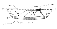
一方、図12に示す従来のパチンコ機201では、遊技領域を従来よりも拡大すると共に、遊技領域を臨む略円形の窓部241が設けられたガラス扉枠204下部に上皿254が一体的に設けられている。そして、図13に示すように、払出し口245より上皿254の貯留部254aに払い出された遊技球Bはガラス扉枠204寄りに案内され、流路が徐々に狭まり且つガラス扉枠204に沿って左右に延設された直線部254fを有する整流部254eで一列に整列され、供給口穴249より図示しない発射装置へ流下する。また、パチンコ機201は、プリペイドカードの読み出し及び書き込み機能を備えたカードユニット20が接続されて内部の遊技球払い出し機構を利用して遊技球の貸し出しを行うCR機と称されるパチンコ遊技機であり、図12に示すように、遊技球の貸し出しに関する操作を行うための貸球操作部246が設けられている。
しかしながら、上述した従来のパチンコ機201では、遊技領域を臨む窓部241、貸球操作部246及び電飾部材262の大きさ又は配置が、ガラス扉枠204下部に設けられた上皿254によって大きく制限されるという問題がある。例えば、窓部241の上下方向におけるサイズや配置が、ガラス扉枠204の窓部241下方に設けられた上皿254によって制約されている。また、パチンコ機201では、窓部241と上皿254との間に貸球操作部246が設けられているので、窓部241の下部周縁領域に電飾部材262を設けたり、より多彩な演出や各種の情報を表示するための液晶表示装置等を設けたりすることができない。
However, in the
解決しようとする課題は、上皿が設けられる遊技機前面における部品設置スペースをより大きく確保できるようにした遊技機を提供することである。 The problem to be solved is to provide a gaming machine that can secure a larger part installation space on the front surface of the gaming machine on which an upper plate is provided.
以下、上記課題を解決するのに適した各手段につき、必要に応じて作用効果等を付記しつつ説明する。
(請求項1)遊技球を媒体として所定の遊技が実行されると共に遊技球を賞球として払出すように構成された本体と、その本体より払い出された遊技球及び遊技者により投入された遊技球を貯留する貯留部、前記本体より払い出された遊技球を前記貯留部へ流入させる流入口、及び前記貯留部に貯留された遊技球を前記本体側へ供給する供給口を有する上皿と、を備えた遊技機において、
前記上皿の貯留部の一部を前記本体より離間して形成することによって前記貯留部と前記本体との間に空間部を形成すると共に、前記貯留部と前記本体との間に各種部材を設けたものであって、
前記貯留部は、前記流入口及び前記供給口に連続する底面部と、その底面部の周囲を取り囲むように立設された前壁部と、前記底面部を挟んで前記前壁部と対向して立設され且つ前記前壁部側へ凸状に形成された後壁部とを備え、
前記後壁部と前記各種部材との間に隙間が形成されたことを特徴とする遊技機。
請求項1に記載の発明によれば、皿部の貯留部の一部を本体より離間して形成することによって貯留部と本体との間に空間部を形成すると共に、貯留部と本体との間に各種部材を設け、特に、貯留部は、流入口及び供給口に連続する底面部と、その底面部の周囲を取り囲むように立設された前壁部と、底面部を挟んで前壁部と対向して立設され且つ前壁部側へ凸状に形成された後壁部とを備え、後壁部と各種部材との間に隙間が形成されているので、当該空間部を各種部材の設置領域等として活用することができる。よって、遊技機の前面に設けられる各種部材の大きさや配置の自由度が大幅に向上される。
Hereinafter, each means suitable for solving the above-described problems will be described with additional effects and the like as necessary.
(Claim 1) A predetermined game is executed using a game ball as a medium, and a main body configured to pay out the game ball as a prize ball, a game ball paid out from the main body, and a player inserted An upper plate having a storage part for storing game balls, an inlet for allowing game balls paid out from the main body to flow into the storage part, and a supply port for supplying the game balls stored in the storage part to the main body side In a gaming machine equipped with
By forming a part of the storage part of the upper plate away from the main body, a space is formed between the storage part and the main body, and various members are provided between the storage part and the main body. Provided,
The storage part is opposed to the front wall part across the bottom surface part, a bottom wall part that is continuous with the inflow port and the supply port, a front wall part that is erected so as to surround the periphery of the bottom part. A rear wall portion that is erected and formed in a convex shape toward the front wall portion side,
A gaming machine , wherein a gap is formed between the rear wall portion and the various members .
According to invention of
(請求項2)前記流入口及び前記供給口は、前記貯留部の後端で左右に離間して設けられ、前記空間部は、前記流入口と前記供給口との間に形成されたことを特徴とする請求項1に記載の遊技機。
請求項2に記載の発明によれば、貯留部の後端で左右に離間して設けられた流入口と供給口との間に空間部を形成したので、空間部のサイズを大きくして各種部材の設置領域等をより大きく確保することができる。
(Claim 2) The inflow port and the supply port are provided apart from each other at the rear end of the storage portion, and the space portion is formed between the inflow port and the supply port. The gaming machine according to
According to the second aspect of the present invention , since the space portion is formed between the inlet and the supply port that are provided to be separated from each other at the rear end of the storage portion, the size of the space portion is increased and various types are provided. It is possible to secure a larger member installation area and the like.
(請求項3)前記空間部は、前記貯留部の左右方向中央に形成されたことを特徴とする請求項2に記載の遊技機。
請求項3に記載の発明によれば、空間部が貯留部の左右方向中央に形成されているので、貯留部において左右均等な強度を確保することができる。
(Claim 3) The gaming machine according to
According to the third aspect of the present invention , since the space portion is formed at the center in the left-right direction of the storage portion, it is possible to ensure equal strength in the left and right directions in the storage portion.
(請求項4)前記貯留部の全体形状が、前記流入口側と前記供給口側とを両端とし且つ前方側へ湾曲するアーチ状に形成されたことを特徴とする請求項2又は3に記載の遊技機。
請求項4に記載の発明によれば、貯留部の全体形状が流入口側と供給口側とを両端とし且つ前方側へ湾曲するアーチ状に形成されているので、アーチ形状の内周側部分となる貯留部と本体との間に確実に空間部を形成することができる。
(Claim 4) The whole shape of the storage part is formed in an arch shape having both the inlet side and the supply port side as both ends and curved forward. Game machines.
According to the invention described in claim 4, since the entire shape of the storage portion is formed in an arch shape having both the inlet side and the supply port side as both ends and curved forward, the inner peripheral side portion of the arch shape A space portion can be reliably formed between the storage portion and the main body.
(請求項5)前記貯留部には、前記前壁部と前記後壁部との間隔が徐々に狭まり、遊技球を一列に整列させて前記供給口より本体側へ流下させる整流部が設けられたことを特徴とする請求項1乃至4のいずれかに記載の遊技機。
請求項5に記載の発明によれば、貯留部に設けられた整流部において前壁部と後壁部との間隔が徐々に狭まっているので、貯留された遊技球を一列に整列させて供給口より本体側へ流下させることができる。
(Claim 5) The storage section is provided with a rectifying section that gradually narrows the gap between the front wall section and the rear wall section, aligns the game balls in a line, and flows down from the supply port to the main body side. The gaming machine according to any one of
According to the fifth aspect of the present invention , since the gap between the front wall portion and the rear wall portion is gradually narrowed in the rectifying portion provided in the storage portion, the stored game balls are supplied in line. Can flow down from the mouth to the main body.
(請求項6)前記整流部を構成する前記前壁部及び前記後壁部の少なくとも一方に遊技球誘導用の傾斜面が形成されたことを特徴とする請求項5に記載の遊技機。
請求項6に記載の発明によれば、整流部を構成する前壁部及び後壁部の少なくとも一方に遊技球誘導用の傾斜面が形成されているので、遊技球が確実に一列に整列され且つ供給口に向かって誘導される。
(Claim 6) The gaming machine according to
According to the sixth aspect of the present invention , since the inclined surface for guiding the game ball is formed on at least one of the front wall portion and the rear wall portion constituting the rectifying portion, the game balls are surely aligned in a line. And it is guided toward the supply port.
本発明によれば、皿部の貯留部の一部を本体より離間して形成することによって貯留部と本体との間に空間部を形成すると共に、貯留部と本体との間に各種部材を設け、特に、貯留部は、流入口及び供給口に連続する底面部と、その底面部の周囲を取り囲むように立設された前壁部と、底面部を挟んで前壁部と対向して立設され且つ前壁部側へ凸状に形成された後壁部とを備え、後壁部と各種部材との間に隙間が形成されているので、当該空間部を各種部材の設置領域等として活用することができる。よって、遊技機の前面に設けられる各種部材の大きさや配置の自由度が大幅に向上される。 According to the present invention, by forming a part of the storage part of the dish part away from the main body, the space part is formed between the storage part and the main body, and various members are provided between the storage part and the main body. In particular, the storage portion is opposed to the front wall portion across the bottom surface portion, the bottom wall portion continuous to the inflow port and the supply port, the front wall portion standing so as to surround the bottom surface portion, and the bottom surface portion. A rear wall portion that is erected and formed in a convex shape toward the front wall portion side, and a gap is formed between the rear wall portion and various members. Can be used as Therefore, the size of various members provided on the front surface of the gaming machine and the degree of freedom of arrangement are greatly improved.
以下、本発明の遊技機を具体化した各実施形態について説明する。最初に、第一の実施形態であるパチンコ遊技機(以下、単に「パチンコ機」と称する)1について説明する。パチンコ機1は、内部の遊技球払い出し機構を利用して遊技球の貸し出しを行うCR機と称されるタイプのパチンコ機であり、図1に示すように、カードユニット20が隣接配置され且つ電気的に接続されている。カードユニット20は、予め金額情報が記録されたプリペイドカードを投入可能なカード投入口21を有し、プリペイドカードから金額情報の読み出し及び書き込みが可能となっている。
Hereinafter, each embodiment which actualized the gaming machine of the present invention will be described. First, a pachinko gaming machine (hereinafter simply referred to as “pachinko machine”) 1 according to the first embodiment will be described. The
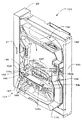
パチンコ機1は、図1乃至図5に示すように、外枠2と、その外枠2の前部に設けられ外枠2の一側部にて開閉可能に支持された前面枠3とを備えている。外枠2は、パチンコ機1のベースとなる枠であり、板材により全体として矩形状に構成されている。尚、本実施の形態では、外枠2は木製であって、上下方向の長さは808mm、左右方向の長さは520mmとなっている。また、前面枠3は合成樹脂、具体的にはABS(アクリロニトリル−ブタジエン−スチレン)樹脂により構成されている。前面枠3の開閉軸線はパチンコ機1の正面から見て左側に上下に延びるように設定されている。尚、外枠2は樹脂により構成されていてもよく、あたかも外枠2及び前面枠3が一体物に見えるように構成されていてもよい。
As shown in FIGS. 1 to 5, the
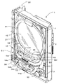
前面枠3には、後述する下皿ユニット51を除く前面枠3の前面側を覆うように、ガラス扉枠4が開閉自在に設けられている。尚、ガラス扉枠4が本発明の開閉枠を構成するものであり、後述する上皿54を除いて外枠2,前面枠3及びガラス扉枠4を含むパチンコ機1のすべての構成部材が本発明の本体を構成するものである。また、ガラス扉枠4の開閉軸線(軸支部)もパチンコ機1の正面から見て左側に上下に延びるように設定されている。詳しくは、ガラス扉枠4の背面図である図5に示すように、ガラス扉枠4の裏側から見て右側の上端部付近に回動軸91が設けられ、図5に示すように前面枠3の正面から見て左側の上端部付近には回動軸91が嵌め込まれる軸受部92が設けられている。また、軸受部92の下方には、上方に突出する突回動軸93が設けられ、ガラス扉枠4の下側面には、前記回動軸91の下方位置において、前記突回動軸93を嵌め込むための図示しない軸受凹部が設けられている。そして、突回動軸93を前記軸受凹部に嵌め込み、回動軸91を軸受部92に嵌め込むことによって、ガラス扉枠4が軸支され開閉可能となる。このように本実施の形態では、回動軸91と突回動軸93を結ぶ線がガラス扉枠4の開閉軸線として設定されている。
A glass door frame 4 is provided on the
また、ガラス扉枠4には、裏側から一対のガラス42が並行して取り付けられている。ガラス扉枠4の左右方向の長さは、前面枠3とほぼ同等であり、そのガラス扉枠4によって前面枠3下部に設けられた下皿ユニット51を除く殆どの部分が覆われるようになっている。
A pair of
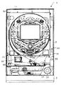
前記前面枠3の後側(ガラス扉枠4の奥、外枠2の内側)には、遊技盤5が着脱可能に装着されている。なお、遊技盤5は、その周縁部が前面枠3の裏側に当接した状態で取り付けられており、図4では、遊技盤5の前面部の略中央部分だけが前面枠3の前面側に露出した状態となっている。この遊技盤5の上下方向の長さは476mm、左右方向の長さは451mmとなっている。また、遊技盤5には、ルータ加工が施されることによって複数の開口部が形成されており、各開口部には、普通入賞チャッカー6、可変入賞装置7、作動チャッカー8、可変表示装置9、スルーチャッカー10等が配設されている。本実施の形態における可変表示装置9は、液晶表示部と、当該液晶表示部の周囲に配設されたセンターフレームと、液晶表示部における表示制御を実行するための表示制御基板とを備えている。
A
尚、表示制御基板を含む各種の制御基板は、図3に示すように、遊技盤5の背面側に設けた透明樹脂製の裏パック5aによって覆われている。また、パチンコ機1の主制御を行うメイン基板はメイン基板ボックス5bに、入賞による遊技球の払い出しやカードユニット20からの貸し出し要求に基づいて遊技球の払い出しを行う払出ユニット5d及び遊技球の発射を行う発射装置31の制御を行う払出発射制御基板は払出発射制御基板ボックス5cにそれぞれ収納されている。
Various control boards including the display control board are covered with a transparent resin back
可変表示装置9の液晶表示部には、例えば左図柄列、中図柄列及び右図柄列の3つの表示列が表示される。各図柄列は複数の図柄によって構成されており、これら図柄が各図柄列毎にスクロールされるように表示画面に可変表示されるようになっている。 For example, three display columns of a left symbol row, a middle symbol row, and a right symbol row are displayed on the liquid crystal display unit of the variable display device 9. Each symbol row is composed of a plurality of symbols, and these symbols are variably displayed on the display screen so as to be scrolled for each symbol row.
また、可変入賞装置7は、通常、遊技球Bが入賞できない状態又は入賞し難い状態になっている。より詳しくは、作動チャッカー8に対し遊技球Bが入賞することに基づいて、可変表示装置9の液晶表示部の図柄が可変表示される。そして、確定された図柄の組合わせが予め設定した特定の図柄の組合わせとなったこと、ここでは停止した図柄が特定の組み合わせであることを必要条件に特別遊技状態が発生し、可変入賞装置7の大入賞口が所定の開放状態となり(具体的には所定時間、所定回数だけ開く)、遊技球Bが入賞しやすい状態(大当り状態)になるよう構成されている。なお、周知のとおり、前記一般入賞口6、可変入賞装置7、作動チャッカー8に遊技球Bが入賞することに基づいて、後述する上皿54(場合によっては下皿53)に対し所定数の景品球が払い出されるようになっている。また、遊技盤5には、遊技球Bの落下方向を適宜分散、調整等するために多数の釘が植設されているとともに、風車等の各種部材(役物)が配設されている。
Further, the variable winning device 7 is normally in a state where the game ball B cannot win or is difficult to win. More specifically, the design of the liquid crystal display unit of the variable display device 9 is variably displayed based on the game ball B winning the operation chucker 8. Then, a special game state is generated on the condition that the determined symbol combination is a specific symbol combination set in advance, and the stopped symbol is a specific combination. 7 is configured to be in a predetermined open state (specifically, opened for a predetermined time and a predetermined number of times), and the game ball B is in a state where it is easy to win (a big hit state). As is well known, based on the fact that the game ball B wins the general winning slot 6, the variable winning device 7, and the operation chucker 8, a predetermined number of the upper plates 54 (in some cases, the lower plate 53) will be described. A prize ball is paid out. The
さて、前記前面枠3は、外形が前記外枠2とほぼ同一形状をなす樹脂ベース11と、この樹脂ベース11の最内周側に位置し略円弧状をなすよう一体形成された内レール12と、主として図の左側の内レール12に対し所定間隔を隔てて前記樹脂ベース11に一体形成された外レール13とを備えている。これら内レール12及び外レール13は遊技球発射ハンドル52の回動操作に基づき発射装置31から発射された遊技球Bを遊技盤5上部へ案内する発射路としての役割を主として果たすものである。従って、内レール12と外レール13とが並行する部分(向かって左側の部分)によって、誘導レールが構成されることとなる。
The
前記内レール12の下端部付近において、遊技盤5には遊技球Bを導出するアウト口25が形成されている。そして、遊技盤5の下部に落下した遊技球の多くは、このアウト口25を通って図示しない球排出路の方へと案内されるようになっている。このような構成の下、前面枠3の内周側の窓孔によって主として遊技領域の外延が確定されており、前面枠3に対し遊技盤5が装着された状態にあっては、内レール12及び外レール13が遊技盤5に当接又は近接した状態となる。そして、発射装置31により発射された遊技球Bは、主として外レール13によって遊技盤5の上部へと案内される。また、遊技盤5には、遊技球の払い出しを行う払出口32が設けられ、この払出口32に連通するようにガラス扉枠4側に払出口45が設けられている(図4及び図5参照)。
In the vicinity of the lower end of the inner rail 12, the
次に、遊技領域について説明する。本実施の形態では、遊技領域を、パチンコ機1の正面から見て、内レール12及び外レール13によって囲まれる領域のうち、内外レール12,13の並行部分である誘導レールの領域を除いた領域としている。また、パチンコ機1において、外レール13の最上部地点から遊技盤5下部までの間の距離は462mm、外レール13の極左位置から内レール12の極右位置までの間の距離は449mmとなっている。また、内レール12の極左位置から内レール12の極右位置までの間の距離は432mmとなっている。
Next, the game area will be described. In the present embodiment, the game area is a region surrounded by the inner rail 12 and the outer rail 13 as viewed from the front of the
ここで、ガラス扉枠4について説明する。ガラス扉枠4には、前記遊技領域の殆どを外部から視認することができるように略楕円形状の窓部41が形成されている。具体的には、前記窓部41は、その左右側の略中央部が、上下側に比べて比較的緩やかに湾曲した形状となっている。なお、前記略中央部が直線状になるようにしてもよい。本実施の形態において、前記窓部41の上端(外レール13の最上部、遊技領域の上端)と、ガラス扉枠4の上端との間の距離(いわゆる上部フレーム部分の上下幅)は50mmとなっており、85mm〜95mm程度上部フレーム幅がある従来技術に比べ、著しく短くなっている。なお、上記距離は、80mm以下であることが望ましく、より望ましくは70mm以下であり、さらに望ましくは60mm以下である。勿論、所定の強度が確保できるのであれば、50mm以下であっても差し支えない。
Here, the glass door frame 4 will be described. The glass door frame 4 is formed with a substantially
また、窓部41の左端と、ガラス扉枠4の左端との間の最短距離(いわゆる左側部フレーム部分の左右幅)は、ガラス扉枠4自体の強度及び支持強度を高めるために比較的大きく設定されている。より詳しくは、図1及び図4を相互に比較すると明らかなように、ガラス扉枠4が閉じられた状態において、外レール13の左側部は勿論、内レール12の左側部も前記左側部フレーム部分によって覆い隠される。すなわち、誘導レールの一部が覆い隠される。このように遊技球Bが一時的に視認困難となったとしても、それは、遊技球Bが遊技領域に案内される通過点に過ぎず、遊技者が主として遊技を楽しむ遊技領域において遊技球Bが視認困難となるわけではない。そのため、実際の遊技に際しては何ら支障が生じない。また、このような支障が生じない一方で、ガラス扉枠4の十分な強度及び支持強度が確保可能となっている。ちなみに、外レール13の左端位置と外枠2の左端位置との左右方向の距離は21mm、遊技領域の右端位置(内レール12の右端位置)と外枠2右端位置との左右方向の距離は44mmとなっている。また、ガラス扉枠4には、図5に示すように、その左右フレーム部分の裏側において、そのガラス扉枠4を補強するための例えば金属製の補強部材43,44が取り付けられている。
The shortest distance between the left end of the
併せて、図1及び図4に示すように、ガラス扉枠4の存在していない前面枠3下部は、例えばABS(アクリロニトリル−ブタジエン−スチレン)樹脂よりなる下皿ユニット51となっている。下皿ユニット51の右下部からは、遊技球発射用ハンドル52が手前側に延設されている。また、下皿ユニット51のほぼ中央部には球受け皿としての景品球払出用の下皿53が設けられている。さらに、下皿ユニット51には下皿53の左側に隣接して灰皿56が設けられている。
In addition, as shown in FIGS. 1 and 4, the lower portion of the
これに対し、ガラス扉枠4における窓部41下方の下部フレームには、上皿54が一体的に設けられている。上皿54は、合成樹脂を成形することによって製造され、ガラス扉枠4の払出し口45より払い出された遊技球及び遊技者により投入された遊技球を貯留する貯留部54a、払出し口45より払い出された遊技球を貯留部54aへ流入させる流入口54l、及び貯留部54aに貯留された遊技球をガラス扉枠4の供給穴49を通して発射装置31側へ供給する供給口54rを有し、流入口54l及び供給口54rの後端面においてガラス扉枠4にビス等を用いて取り付け固定されている。
On the other hand, the
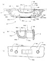
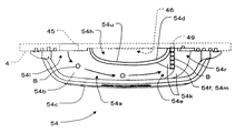
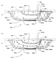
上皿54の貯留部54aは、流入口54l及び供給口54rに連続する底面部54bと、底面部54bの周囲を取り囲むように立設された前壁部54cと、底面部54bを挟んで前壁部54cと対向するように流入口54lと供給口54rとの間に立設され且つ前壁部54c側へ凸状となるようにに湾曲形成された後壁部54dとを有している。底面部54bは、左右方向に細長く且つガラス扉枠4から前方へ張り出すように形成されている。また、底面部54b後部の流入口54lと供給口54rとの間には前方側へ凹状をなす凹状輪郭部54uが形成され、上述した後壁部54dは凹状輪郭部54uに沿って立設されている。後壁部54dは、左右方向中央部でガラス扉枠4より数十mm程度(例えば、30〜50mm)前方側へ離間しており、後壁部54dとガラス扉枠4との間に空間部54hが形成される構造となっている。尚、図2(a)では、上皿54が取り付けられるガラス扉枠4を点線で示している。
The
貯留部54aには、後壁部54dの右側に、遊技球を一列に整列させて供給口54rより供給穴49を通して発射装置31側へ流下させる整流部54eが設けられている。整流部54eには、後述する直線部54fを挟んで前壁部54c及び後壁部54dに遊技球を直線部54fへ誘導するための傾斜壁54kがそれぞれ形成されており、前壁部54cと後壁部54dとの間隔が徐々に狭まる構造となっている。整流部54eには、底面部54b上で前後方向に延設され且つ前方側から供給穴49の位置する後方側に向かって下り傾斜する直線部54fが設けられ、この直線部54fの底面に細長い長方形状の金属板54mが装着されている。金属板54mは、遊技球の流れをスムーズにする機能、底面を補強して摩擦による削れを防止する機能、ノイズを防止する機能等を有している。また、金属板54mの下流端側には球抜き穴54jが形成されている。この球抜き穴54jは、通常の状態において直線部54fの底面裏側をスライド自在に設けられる開閉弁54iによって閉塞されており、開閉弁54iが前壁部54cに設けられる球抜きレバー54gの操作により移動されたときに、球抜き穴54jが開放されて貯留部54a内に貯留されていた遊技球を図示しない球抜き通路を介して下皿53に移動せしめるものである。
On the right side of the
ここで、上皿54の貯留部54aにおける遊技球Bの流れについて、図6を参照しつつ説明する。遊技球Bは、払出口45より払い出されると流入口54lより貯留部54a内に流入し、緩やかに右下がりに傾斜する底面部54bと、前壁部54c及び後壁部54dとに案内されて貯留部54a右側の供給口54rへ向かって転動して整流部54eに到達する。また、遊技者によって遊技球Bが貯留部54a内へ投入された場合も、同様に、底面部54b等に案内されて転動して整流部54eへ到達する。そして、遊技球Bは整流部54eの直線部54fを挟んで両側に設けられた傾斜壁54kによって誘導されて一列に整列されると共に、直線部54f上を下り傾斜する後方側(ガラス扉枠4側)へ転動して金属板54mの下流端より供給穴49へ流下する。供給穴49から球送り装置48へ供給された遊技球は、1個ずつ発射レール33に導かれ、発射装置31によって発射される。
Here, the flow of the game ball B in the
ガラス扉枠4の窓部41下方において空間部54hを挟んで上皿54の後壁部54dに対向する領域には、遊技球の貸し出し関する操作を行うための貸球操作部46が設けられている。貸球操作部46は、図2(c)に示すように、遊技球の貸し出し可能状態をランプによって示す貸出ボタンランプ46a、遊技球の貸し出しを行うための貸出ボタン46b、プリペイドカードの返却を行うための返却ボタン46c、プリペイドカードの残り度数を表示する度数表示LED46dとを備えている。尚、図2(c)は、図2(b)におけるC線矢視方向における図である。遊技者側を基準としたとき、貸出ボタン46b及び返却ボタン46cは後壁部54dよりも奥に位置するため、遊技者が上皿54上で手を移動する際等に誤って貸出ボタン46b又は返却ボタン46cに触れて遊技球の貸し出し又はプリペイドカードの返却が行われることが防止される。また、遊技者は、斜め上方から貸球操作部46を見ることができるので、度数表示LED46dにおける残り度数を確認することができ、貸出ボタン46b、返却ボタン46cを操作する際には、空間部54h上部に手を差し込むようにしてこれらのボタン46b、46cを押下することができる。
In a region facing the
ガラス扉枠4の周囲(例えばコーナー部分や窓部41の周縁)には、各種ランプ、LED等の発光手段を備えた電飾部材62が設けられている。これら電飾部材62は、大当り時や所定のリーチ時等の遊技状態の変化に応じて点灯、点滅のように発光手段の発光態様が変更制御され遊技中の演出効果を高める役割を果たすようになっている。特に、本実施形態では、窓部41の真下部分を含む窓部41周縁全周に亘って電飾部材62が配置されているため、極めて効果的な演出を行うことが可能となっている。勿論、これら電飾部材62を、遊技盤5に設ける構成(コーナー飾りと称される電飾部材62を遊技盤5のコーナー部等に配設する)としてもよいし、場合によっては前面枠3に設ける構成としてもよい。更には、前後一対のガラス42間に配設する構成としてもよい。
Around the glass door frame 4 (for example, the corner portion and the peripheral edge of the window portion 41), an
また、周知のとおり、前面枠3が外枠2に対し閉じられると自動的にロックがかかるようになっており、所定のキー操作が行われることによりロックが解除されるようになっている。同様に、ガラス扉枠4が前面枠3に対し閉じられると自動的にロックがかかり、別途のキー操作が行われることによりロックが解除されるようになっている。このようにロック及びロック解除を行うためのロック機構が前面枠3の右下部、つまり下皿ユニット51の右端部に設けられている。ロック機構には、鍵穴を有するキーシリンダ(解除キー)55、前面枠3及び外枠2間でのロック及び解除を行うための第2ロック機構が含まれる。本実施の形態では、最も幅狭で、遊技領域の拡張を阻害する前面枠の右中央部ではなく、比較的にスペースにゆとりのある前面枠3の右下部に、キーシリンダ55をはじめとする上記ロック機構(特にキーシリンダ55)が配設されている。換言すれば、キーシリンダ55は、遊技領域の最大幅となる位置を避けて配置されている。このような構成により、遊技領域の拡張をより容易且つ確実に図ることができる。
Further, as is well known, when the
勿論、最も幅狭な部分以外であれば、上記以外の部位に設けてもよく、例えば、前面枠3の右上部に設けるような構成としてもよい。また、上記例では、第1ロック機構及び第2ロック機構をキーシリンダ55でともにロック状態を解除可能としたが、それぞれの解除のためのキーシリンダを別体で設けることとしてもよい。
Of course, as long as it is other than the narrowest part, it may be provided in a part other than the above. In the above example, both the first lock mechanism and the second lock mechanism can be released by the
以上詳述したことから明らかなように、本実施形態によれば、パチンコ遊技機1において、上皿54の貯留部54aの一部をガラス扉枠4より離間して形成することによって貯留部54aとガラス扉枠4との間に空間部54hを形成したので、当該空間部54hを各種部材(上記実施形態では、貸球操作部46)の設置領域等として活用することができる。よって、ガラス扉枠4の前面に設けられる各種部材の大きさや配置の自由度が大幅に向上される。
As is clear from the above detailed description, according to the present embodiment, in the
また、貯留部54aの後端で左右に離間して設けられた流入口54lと供給口54rとの間に空間部54hを形成したので、空間部54hのサイズを大きくして各種部材の設置領域等をより大きく確保することができる。また、空間部54hが貯留部54aの左右方向中央に形成されているので、貯留部54aを構成する樹脂部材において左右均等な強度を確保することができる。また、貯留部54aの全体形状が流入口54l側と供給口54r側とを両端とし且つ前方側へ湾曲するアーチ状に形成されているので、アーチ形状の内周側部分となる貯留部54aとガラス扉枠4との間に確実に空間部54hを形成することができる。
In addition, since the
また、貯留部54aに設けられた整流部54eにおいて前壁部54cと後壁部54dとの間隔が徐々に狭まっているので、貯留された遊技球を一列に整列させて供給口54rより発射装置31側へ流下させることができる。整流部54eに遊技球誘導用の傾斜面54kが形成されているので、遊技球が確実に一列に整列され且つ供給口54rに向かって誘導される。特に、遊技球誘導用の傾斜面54kが前壁部54c側だけでなく、後壁部54d側にも形成されているので、遊技球が後壁部54d側で滞ることなく供給口54rに向かって誘導される。
Moreover, since the space | interval of the
また、整流部54eは、底面部54b上で前後方向に延設され且つ前方側から供給口54rが設けられる後方側に向かって下り傾斜する直線部54fを備えている。よって、流入口54lから底面部54b上に流入した遊技球は、前壁部54c側へ凸状に形成された後壁部54dを迂回して供給口54rへ向かう経路に沿って転動し、整流部54eの直線部54fにおいて一列に円滑に整列されて供給口54rより発射装置31側へ確実に流下する。
The rectifying
次に、本発明の第二の実施形態について、図7を参照しつつ説明する。第二の実施形態は、複数種類の図柄が表示された複数の回転リールを有し、各回転リールの回転停止時の図柄の組合わせに基づく入賞態様に応じて遊技球が払い出されるパチロット遊技機(以下、単に「パチロット機」と称する)である。本実施形態のパチロット機101は、図7に示すように、正面側に開口すると共に、複数種類の図柄が表示された図示しない複数(3個)の回転リールが収容される本体枠120と、本体枠120の前面を覆うように開閉可能に取り付けられ、各回転リールの図柄を視認可能な表示窓163を設けた合成樹脂製のフロントパネル160とを備えている。また、パチロット機101には、上述した第一の実施形態と同様に、カードユニット20が隣接配置され且つ電気的に接続されている。
Next, a second embodiment of the present invention will be described with reference to FIG. The second embodiment has a plurality of rotating reels on which a plurality of types of symbols are displayed, and a pachilot gaming machine in which game balls are paid out according to a winning mode based on a combination of symbols when rotation of each rotating reel is stopped (Hereinafter simply referred to as “pachilot machine”). As shown in FIG. 7, the
また、フロントパネル160には、装飾ランプ162、前方へ突出する台状に形成された上皿154、払い出された遊技球又は上皿154より誘導された遊技球を受けて貯留する下皿170等が設けられている。上皿154の上面には、各回転リールの回転停止時の図柄の組合わせに基づく入賞態様に応じてフロントパネル160の払出し口145より払い出された遊技球及び遊技者により投入された遊技球を貯留する貯留部154a、払出し口145より払い出された遊技球を貯留部154aへ流入させる流入口154l、及び貯留部154aに貯留された遊技球をフロントパネル160の供給穴149を通して本体側へ供給する供給口154rが設けられている。
The
上皿154の貯留部154aは、流入口154l及び供給口154rに連続する底面部154bと、底面部154bの周囲を取り囲むように立設された前壁部154cと、底面部154bを挟んで前壁部154cと対向するように流入口154lと供給口154rとの間に立設され且つ前壁部154c側へ凸状となるように湾曲形成された後壁部154dとを有している。底面部154bは、左右方向に細長く且つ本体側から前方へ張り出すように形成されている。また、底面部154b後部の流入口154lと供給口154rとの間には前方側へ凹状をなす凹状輪郭部が形成され、上述した後壁部154dは凹状輪郭部に沿って立設されている。後壁部154dは、左右方向中央部でフロントパネル160より数十mm程度(例えば、30〜50mm)前方側へ離間しており、後壁部154dとフロントパネル160との間に空間部154hが形成される構造となっている。
The
フロントパネル160において空間部154hを挟んで上皿154の後壁部154dに対向する領域には、遊技球の貸し出し関する操作を行うための貸球操作部146が設けられている。貸球操作部146は、遊技球の貸し出し可能状態をランプによって示す貸出ボタンランプ146a、遊技球の貸し出しを行うための貸出ボタン146b、プリペイドカードの返却を行うための返却ボタン146c、プリペイドカードの残り度数を表示する度数表示LED146dとを備えている。遊技者側を基準としたとき、貸出ボタン146b及び返却ボタン146cは後壁部154dよりも奥に位置するため、遊技者が上皿154上で手を移動する際等に誤って貸出ボタン146b又は返却ボタン146cに触れて遊技球の貸し出し又はプリペイドカードの返却が行われることが防止される。また、遊技者は、斜め上方から貸球操作部146を見ることができるので、度数表示LED146dにおける残り度数を確認することができ、貸出ボタン146b、返却ボタン146cを操作する際には、空間部154h上部に手を差し込むようにしてこれらのボタン146b、146cを押下することができる。
In a region of the
また、前壁部154cの上面には、クレジットされている遊技球を投入するためのベットスイッチ165や、クレジットされている遊技球を払い出すためのキャンセルスイッチ166が設けられている。また、前壁部154cの前面は操作部164となっており、回転リールの回転起動操作を行うスタートレバー167、及び左・中・右の回転リールにそれぞれ対応して設けられたストップスイッチ168が設けられている。
In addition, a
以上詳述したことから明らかなように、本実施形態によれば、パチロット遊技機101は、上皿154の貯留部54aの一部をフロントパネル160より離間して形成することによって貯留部154aとフロントパネル160との間に空間部154hを形成したので、当該空間部154hを各種部材(上記実施形態では貸球操作部146)の設置領域等として活用することができる。よって、フロントパネル160の前面に設けられる各種部材の大きさや配置の自由度が大幅に向上される。
As is clear from the above detailed description, according to the present embodiment, the
また、貯留部154aの後端で左右に離間して設けられた流入口154lと供給口154rとの間に空間部154hを形成したので、空間部154hのサイズを大きくして各種部材の設置領域等をより大きく確保することができる。また、空間部154hが貯留部154aの左右方向中央に形成されているので、貯留部154aを構成する樹脂部材において左右均等な強度を確保することができる。また、貯留部154aの全体形状が流入口154l側と供給口154r側とを両端とし且つ前方側へ湾曲するアーチ状に形成されているので、アーチ形状の内周側部分となる貯留部154aとフロントパネル160との間に確実に空間部154hを形成することができる。
In addition, since the
尚、本発明は上述した各実施の形態に限定されるものではなく、本発明の主旨を逸脱しない範囲で種々の変更を施すことが可能である。例えば、前記第一の実施形態では、上皿54の後壁部54dとガラス扉枠4との間に形成された空間には、貸球操作部46を設けた例を示したが、これには限られず、遊技領域の一部、電飾部材、貸球操作部、液晶表示装置等の各種部材の設置スペースとして活用することが考えられる。
The present invention is not limited to the above-described embodiments, and various modifications can be made without departing from the spirit of the present invention. For example, in the first embodiment, the example in which the ball
また、前記第一の実施形態では、ガラス扉枠4に上皿54が設けられる例を示したが、ガラス扉枠の下方に別体で前面枠3に対して開閉可能な上皿板を設け、その上皿板に上皿54を設ける構成のパチンコ機に対して本発明を適用してもよい。尚、本変形例において、上皿板が本発明の開閉枠を構成するものである。或いは、第一の実施形態において、上皿54を開閉枠としてのガラス扉枠4や上皿板に設けることなく、前面枠3に設ける構成としてもよい。同様に、第二の実施形態では、上皿154を開閉枠としてのフロントパネル160に設けることなく、本体枠120に設ける構成としてもよい。
In the first embodiment, the
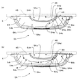
また、前記第一の実施形態では、貯留部54aの整流部54eに直線部54fを前後方向に設ける構成としたが、図8(a)に示す第1の変形例のように、ガラス扉枠4に対して斜め方向に延設され且つ前方側から後方側に向かって下り傾斜する直線部54nを設ける構成としてもよい。本変形例によれば、図8(b)に示すように、遊技球Bは、払出口45より払い出されると流入口54lより貯留部54a内に流入し、緩やかに右下がりに傾斜する底面部54b,前壁部54c及び後壁部54dに案内され、前壁部54c側へ凸状に形成された後壁部54dを迂回して供給口54rへ向かう経路に沿って転動して貯留部54a右側の整流部54eに到達する。また、遊技者によって遊技球Bが貯留部54a内へ投入された場合も、同様に、底面部54b等に案内されて転動して整流部54eへ到達する。そして、遊技球Bは直線部54nの両側に設けられた傾斜壁54kによって誘導されて一列に整列されると共に、直線部54n上を下り傾斜する後方側(ガラス扉枠4側)へ転動して金属板54mの下流端より供給穴49へ流下する。
In the first embodiment, the
また、図9(a)に示す第2の変形例のように、底面部54b上で流入口54lから供給口54rに至る曲線状の経路に沿って延設され且つ前方側から供給口54rが設けられる後方側に向かって下り傾斜する曲線部54oを設ける構成としてもよい。本変形例によれば、図9(b)に示すように、遊技球Bは、払出口45より払い出されると流入口54lより貯留部54a内に流入し、緩やかに右下がりに傾斜する底面部54b,前壁部54c及び後壁部54dに案内され、前壁部54c側へ凸状に形成された後壁部54dを迂回して供給口54rへ向かう経路に沿って転動して貯留部54a右側の整流部54eに到達する。また、遊技者によって遊技球Bが貯留部54a内へ投入された場合も、同様に、底面部54b等に案内されて転動して整流部54eへ到達する。そして、遊技球Bは曲線部54oの両側に設けられた傾斜壁54kによって誘導されて一列に整列されると共に、曲線部54o上を下り傾斜する後方側(ガラス扉枠4側)へ転動して金属板54mの下流端より供給穴49へ流下する。
Further, as in the second modification shown in FIG. 9A, the
また、図10(a)に示す第3の変形例のように、底面部54b上で供給口54rに対して流入口54lとは反対側(右側)にて左右方向に延設され且つ供給口54rが設けられる左方向に向かって下り傾斜する直線部54pを設ける構成としてもよい。本変形例によれば、図10(b)に示すように、遊技球Bは、払出口45より払い出されると流入口54lより貯留部54a内に流入し、緩やかに右下がりに傾斜する底面部54b,前壁部54c及び後壁部54dに案内され、前壁部54c側へ凸状に形成された後壁部54dを迂回して供給口54rへ向かう経路に沿って転動して貯留部54a右側の整流部54eに到達する。また、遊技者によって遊技球Bが貯留部54a内へ投入された場合も、同様に、底面部54b等に案内されて転動して整流部54eへ到達する。そして、遊技球Bは直線部54pの両側に設けられた傾斜壁54kによって誘導されて一列に整列されると共に、直線部54p上を下り傾斜する左側へ転動して金属板54mの下流端より供給穴49へ流下する。
Further, as in the third modified example shown in FIG. 10A, the supply port is extended in the left-right direction on the side (right side) opposite to the inlet 54l with respect to the
また、前記第一実施の形態では、上皿54の後壁部54dと対向するガラス扉枠4上を部品設置領域として活用した例を示したが、後壁部54dとガラス扉枠4との間に形成された空間部54hの上面を塞ぐカバー部材を設け、そのカバー部材を各種部材の設置領域等として活用するように構成してもよい。例えば、第4の変形例では、図11(a)及び(b)に示すように、空間部54hの上面を樹脂製のカバー部材47で塞ぎ、このカバー部材47上に貸球操作部46を設ける構成としたものである。本変形例においても、ガラス扉枠4の前面に設けられる各種部材の大きさや配置の自由度が大幅に向上される。尚、前記第二の実施形態に対しても本変形例と同様に空間部154hの上面を塞ぐカバー部材を設け、そのカバー部材を各種部材の設置領域等として活用するように構成してもよい。
In the first embodiment, the example in which the upper part of the glass door frame 4 facing the
(付記)(Appendix)
上述した実施形態から、以下に示す本発明の各手段を抽出することができる。以下、各手段につき、必要に応じて作用効果等を付記しつつ説明する。 The following means of the present invention can be extracted from the embodiment described above. In the following, each means will be described with the effects and the like added as necessary.
1.遊技球を媒体として所定の遊技が実行されると共に遊技球を賞球として払出すように構成された本体と、その本体より払い出された遊技球及び遊技者により投入された遊技球を貯留する貯留部、前記本体より払い出された遊技球を前記貯留部へ流入させる流入口、及び前記貯留部に貯留された遊技球を前記本体側へ供給する供給口を有する上皿と、を備えた遊技機において、 1. A main body configured to execute a predetermined game using a game ball as a medium and pay out the game ball as a prize ball, a game ball paid out from the main body, and a game ball thrown by the player are stored. A storage unit, an inflow port through which the game balls paid out from the main body flow into the storage unit, and an upper plate having a supply port for supplying the game balls stored in the storage unit to the main body side. In gaming machines,
前記上皿の貯留部の一部を前記本体より離間して形成することによって前記貯留部と前記本体との間に空間部を形成したことを特徴とする遊技機。 A gaming machine, wherein a space portion is formed between the storage portion and the main body by forming a part of the storage portion of the upper plate away from the main body.
手段1によれば、上皿の貯留部の一部を本体より離間して形成することによって貯留部と本体との間に空間部を形成したので、当該空間部を各種部材の設置領域等として活用することができる。よって、遊技機の前面に設けられる各種部材の大きさや配置の自由度が大幅に向上される。 According to the
2.前記流入口及び前記供給口は、前記貯留部の後端で左右に離間して設けられ、前記空間部は、前記流入口と前記供給口との間に形成されたことを特徴とする手段1に記載の遊技機。 2. The inflow port and the supply port are spaced apart from each other at the rear end of the storage portion, and the space portion is formed between the inflow port and the supply port. The gaming machine described in 1.
手段2によれば、貯留部の後端で左右に離間して設けられた流入口と供給口との間に空間部を形成したので、空間部のサイズを大きくして各種部材の設置領域等をより大きく確保することができる。 According to the
3.前記空間部は、前記貯留部の左右方向中央に形成されたことを特徴とする手段2に記載の遊技機。 3. The gaming machine according to
手段3によれば、空間部が貯留部の左右方向中央に形成されているので、貯留部において左右均等な強度を確保することができる。 According to the
4.前記貯留部の全体形状が、前記流入口側と前記供給口側とを両端とし且つ前方側へ湾曲するアーチ状に形成されたことを特徴とする手段2又は3に記載の遊技機。 4). The gaming machine according to
手段4によれば、貯留部の全体形状が流入口側と供給口側とを両端とし且つ前方側へ湾曲するアーチ状に形成されているので、アーチ形状の内周側部分となる貯留部と本体との間に確実に空間部を形成することができる。 According to the means 4, since the entire shape of the storage portion is formed in an arch shape having both the inlet side and the supply port side as both ends and curved forward, the storage portion serving as the inner peripheral side portion of the arch shape; A space can be reliably formed between the main body.
5.前記貯留部は、前記流入口及び前記供給口に連続する底面部と、その底面部の周囲を取り囲むように立設された前壁部と、前記底面部を挟んで前記前壁部と対向して立設され且つ前記前壁部側へ凸状に形成された後壁部とを備えたことを特徴とする手段1乃至4のいずれかに記載の遊技機。 5. The storage part is opposed to the front wall part across the bottom surface part, a bottom wall part that is continuous with the inflow port and the supply port, a front wall part that is erected so as to surround the periphery of the bottom part. The game machine according to any one of
手段5によれば、底面部を挟んで前壁部と対向して立設された後壁部が前壁部側へ凸状に形成されて、後壁部と本体との間に確実に空間を形成することができる。 According to the
6.前記貯留部には、前記前壁部と前記後壁部との間隔が徐々に狭まり、遊技球を一列に整列させて前記供給口より本体側へ流下させる整流部が設けられたことを特徴とする手段5に記載の遊技機。 6). The storage part is provided with a rectifying part that gradually narrows the space between the front wall part and the rear wall part, aligns the game balls in a line and flows down from the supply port to the main body side. A gaming machine according to
手段6によれば、貯留部に設けられた整流部において前壁部と後壁部との間隔が徐々に狭まっているので、貯留された遊技球を一列に整列させて供給口より本体側へ流下させることができる。 According to the means 6, since the space between the front wall portion and the rear wall portion is gradually narrowed in the rectifying portion provided in the storage portion, the stored game balls are aligned in a line and moved from the supply port to the main body side. Can flow down.
7.前記整流部を構成する前記前壁部及び前記後壁部の少なくとも一方に遊技球誘導用の傾斜面が形成されたことを特徴とする手段6に記載の遊技機。 7). The gaming machine according to claim 6, wherein an inclined surface for guiding a game ball is formed on at least one of the front wall portion and the rear wall portion constituting the rectifying portion.
手段7によれば、整流部を構成する前壁部及び後壁部の少なくとも一方に遊技球誘導用の傾斜面が形成されているので、遊技球が確実に一列に整列され且つ供給口に向かって誘導される。 According to the means 7, since the inclined surface for guiding the game ball is formed on at least one of the front wall portion and the rear wall portion constituting the rectifying portion, the game balls are surely aligned in a line and directed toward the supply port. Be guided.
8.前記遊技球誘導用の傾斜面が、前記前壁部及び前記後壁部の両方に形成されたことを特徴とする手段7に記載の遊技機。 8). The gaming machine according to claim 7, wherein the game ball guiding inclined surface is formed on both the front wall portion and the rear wall portion.
手段8によれば、遊技球誘導用の傾斜面が前壁部だけでなく、後壁部にも形成されているので、遊技球が後壁部側で滞ることなく供給口に向かって誘導される。 According to the means 8, since the inclined surface for guiding the game ball is formed not only on the front wall portion but also on the rear wall portion, the game ball is guided toward the supply port without stagnation on the rear wall side. The
9.前記流入口及び前記供給口は、前記貯留部の後端で左右に離間して設けられ、前記後壁部は、前記流入口と前記供給口との間に形成されたことを特徴とする手段6乃至8のいずれかに記載の遊技機。 9. The inflow port and the supply port are spaced apart from each other at the rear end of the storage portion, and the rear wall portion is formed between the inflow port and the supply port. The gaming machine according to any one of 6 to 8.
手段9によれば、貯留部の後端で左右に離間して設けられ流入口と供給口との間に底面部を挟んで前壁部と対向して後壁部が立設され且つその後壁部が前壁部側へ凸状に形成されているので、後壁部と本体との間に確実に空間が形成される。 According to the means 9, the rear wall portion is provided upright at the rear end of the storage portion so as to be separated from the left and right, with the bottom surface portion sandwiched between the inlet and the supply port, facing the front wall portion, and the rear wall. Since the portion is formed in a convex shape toward the front wall portion, a space is reliably formed between the rear wall portion and the main body.
10.前記整流部は、前記底面部上で前後方向に延設され且つ前方側から前記供給口が設けられる後方側に向かって下り傾斜する直線部を備えたことを特徴とする手段9に記載の遊技機。 10. 10. The game according to claim 9, wherein the rectifying unit includes a linear part that extends in the front-rear direction on the bottom surface part and slopes downward from the front side toward the rear side where the supply port is provided. Machine.
手段10によれば、流入口から底面部上に流入した遊技球は、前壁部側へ凸状に形成された後壁部を迂回して供給口へ向かう経路に沿って転動し、底面部上で前後方向に延設され且つ前方側から供給口が設けられる後方側に向かって下り傾斜する整流部の直線部において一列に円滑に整列されて供給口より本体側へ確実に流下する。 According to the
11.前記整流部は、前記底面部上で前記供給口に対して前記払出口とは反対側にて左右方向に延設され且つ前記供給口が設けられる方向に向かって下り傾斜する直線部を備えたことを特徴とする手段9に記載の遊技機。 11. The rectifying unit includes a linear portion that extends in the left-right direction on the bottom surface of the supply port on the opposite side of the supply port and inclines downward in the direction in which the supply port is provided. 10. A gaming machine according to claim 9, characterized by the above.
手段11によれば、流入口から底面部上に流入した遊技球は、前壁部側へ凸状に形成された後壁部を迂回して供給口へ向かう経路に沿って転動し、底面部上で供給口に対して払出口とは反対側にて左右方向に延設され且つ供給口が設けられる方向に向かって下り傾斜する整流部の直線部において一列に円滑に整列されて供給口より本体側へ確実に流下する。 According to the
12.前記整流部は、前記底面部上で前記本体に対して斜め方向に延設され且つ前方側から前記供給口が設けられる後方側に向かって下り傾斜する直線部を備えたことを特徴とする手段9に記載の遊技機。 12 The rectifying unit includes a linear part that extends obliquely with respect to the main body on the bottom surface part, and that slopes downward from the front side toward the rear side where the supply port is provided. 9. The gaming machine according to 9.
手段12によれば、流入口から底面部上に流入した遊技球は、前壁部側へ凸状に形成された後壁部を迂回して供給口へ向かう経路に沿って転動し、底面部上で本体に対して斜め方向に延設され且つ前方側から供給口が設けられる後方側に向かって下り傾斜する整流部の直線部において一列に円滑に整列されて供給口より本体側へ確実に流下する。 According to the means 12, the game ball that has flowed into the bottom surface portion from the inflow port rolls along the path toward the supply port, bypassing the rear wall portion formed in a convex shape toward the front wall portion side. In the straight portion of the rectifying unit that extends obliquely with respect to the main body and tilts downward from the front side toward the rear side where the supply port is provided, it is smoothly aligned in a line and reliably from the supply port to the main body side. To flow down.
13.前記整流部は、前記底面部上で前記払出口から前記供給口に至る曲線状の経路に沿って延設され且つ前方側から前記供給口が設けられる後方側に向かって下り傾斜する曲線部であることを特徴とする手段9に記載の遊技機。 13. The rectifying part is a curved part that extends along a curved path from the payout port to the supply port on the bottom surface part and is inclined downward from the front side toward the rear side where the supply port is provided. 10. The gaming machine according to means 9, which is characterized in that it exists.
手段13によれば、流入口から底面部上に流入した遊技球は、前壁部側へ凸状に形成された後壁部を迂回して供給口へ向かう経路に沿って転動し、底面部上で払出口から供給口に至る曲線状の経路に沿って延設され且つ前方側から供給口が設けられる後方側に向かって下り傾斜する整流部の曲線部において一列に円滑に整列されて供給口より本体側へ確実に流下する。 According to the means 13, the game ball that has flowed into the bottom surface portion from the inflow port rolls along the path toward the supply port, bypassing the rear wall portion formed in a convex shape toward the front wall portion side. Smoothly aligned in a line at the curvilinear portion of the rectifying portion that extends along a curved path from the discharge outlet to the supply port on the portion and descends from the front side toward the rear side where the supply port is provided. It flows down from the supply port to the main body.
14.前記貯留部と前記本体との間に形成された前記空間部の上面を塞ぐカバー部材を備えたことを特徴とする手段1乃至13のいずれかに記載の遊技機。 14 The gaming machine according to any one of
手段14によれば、貯留部と本体との間に形成された空間部の上面を塞ぐカバー部材を備えているので、そのカバー部材を各種部材(例えば、操作スイッチを設けたパネル等)の設置領域等として活用することができる。 According to the means 14, since the cover member which closes the upper surface of the space part formed between the storage part and the main body is provided, the cover member is installed with various members (for example, a panel provided with an operation switch). It can be used as an area.
15.前記遊技機は、パチンコ遊技機であることを特徴とする手段1乃至14のいずれかに記載の遊技機。 15. The gaming machine according to any one of
手段15によれば、パチンコ遊技機の前面に設けられる各種部材の大きさや配置の自由度が大幅に向上される。 According to the means 15, the size of various members provided on the front surface of the pachinko gaming machine and the degree of freedom of arrangement are greatly improved.
16.前記本体は、前面側へ開閉可能に設けられ且つ前記上皿が取り付けられる開閉枠を備え、 16. The main body is provided with an open / close frame that is provided to be openable and closable to the front side and to which the upper plate is attached,
前記上皿の貯留部の一部を前記開閉枠より離間して形成することによって前記貯留部と前記開閉枠との間に空間部を形成したことを特徴とする手段15に記載の遊技機。 The gaming machine according to claim 15, wherein a space portion is formed between the storage portion and the opening / closing frame by forming a part of the storage portion of the upper plate away from the opening / closing frame.
手段16によれば、上皿の貯留部の一部を開閉枠より離間して形成することによって貯留部と開閉枠との間に空間部を形成したので、当該空間部を各種部材の設置領域等として活用することにより、開閉枠に設けられる各種部材の大きさや配置の自由度が大幅に向上される。 According to the means 16, since the space portion is formed between the storage portion and the opening / closing frame by forming a part of the storage portion of the upper plate away from the opening / closing frame, the space portion is used as an installation area for various members. By utilizing as such, the size of various members provided in the opening / closing frame and the degree of freedom of arrangement are greatly improved.
17.前記開閉枠は、遊技盤を臨む窓部にガラスが取り付けられたガラス扉枠であることを特徴とする手段16に記載の遊技機。 17. The gaming machine according to claim 16, wherein the opening / closing frame is a glass door frame in which glass is attached to a window portion facing the game board.
手段17によれば、上皿の貯留部とガラス扉枠との間に空間部が形成されているので、当該空間部を各種部材の設置領域等として活用することにより、ガラス扉枠に設けられる各種部材の大きさや配置の自由度が大幅に向上される。 According to the means 17, since the space part is formed between the storage part of the upper plate and the glass door frame, the space part is provided in the glass door frame by utilizing the space part as an installation area for various members. The size of various members and the freedom of arrangement are greatly improved.
18.前記開閉枠は、遊技盤を臨む窓部にガラスが取り付けられたガラス扉枠の下方にて、そのガラス扉枠とは別体で設けられた上皿板であることを特徴とする手段16に記載の遊技機。 18. The open / close frame is an upper plate provided separately from the glass door frame below the glass door frame in which glass is attached to the window facing the game board. The gaming machine described.
手段18によれば、上皿の貯留部と上皿板との間に空間部が形成されているので、当該空間部を各種部材の設置領域等として活用することにより、上皿板に設けられる各種部材の大きさや配置の自由度が大幅に向上される。 According to the means 18, since the space part is formed between the storage part of the upper dish and the upper dish plate, the space part is provided on the upper dish plate by utilizing the space part as an installation area for various members. The size of various members and the freedom of arrangement are greatly improved.
19.前記遊技機は、複数種類の図柄が表示された複数の回転リールを有し、前記各回転リールの回転停止時の図柄の組合わせに基づく入賞態様に応じて遊技球が払い出されるパチロット遊技機であることを特徴とする手段1乃至14のいずれかに記載の遊技機。 19. The gaming machine is a pacilot gaming machine having a plurality of rotating reels on which a plurality of types of symbols are displayed, and game balls are paid out according to a winning mode based on a combination of symbols when the rotation of the rotating reels is stopped. The gaming machine according to any one of
手段19によれば、パチロット遊技機の前面に設けられる各種部材の大きさや配置の自由度が大幅に向上される。 According to the means 19, the size and the degree of freedom of arrangement of various members provided on the front surface of the pacilot gaming machine are greatly improved.
本発明は、遊技球を媒体として所定の遊技が実行されると共に遊技球を賞球として上皿へ払い出すように構成されたパチンコ遊技機やパチロット遊技機等の各種遊技機に適用可能である。 The present invention can be applied to various gaming machines such as a pachinko gaming machine and a pacilot gaming machine configured to execute a predetermined game using a gaming ball as a medium and pay out the gaming ball as a prize ball to an upper plate. .
1 パチンコ遊技機(遊技機)
4 ガラス扉枠(開閉枠)
54 上皿
54a 貯留部
54b 底面部
54c 前壁部
54d 後壁部
54e 整流部
54f,54n,54p 直線部
54o 曲線部
54k 傾斜壁
54h 空間部
54l 流入口
54r 供給口
54u 凹状輪郭部
101 パチロット遊技機(遊技機)
154 上皿
154a 貯留部
154b 底面部
154c 前壁部
154d 後壁部
154h 空間部
154l 流入口
154r 供給口
160 フロントパネル(開閉枠)
1 Pachinko machine (game machine)
4 Glass door frame (open / close frame)
54
154
Claims (6)
前記皿部の貯留部の一部を前記本体より離間して形成することによって前記貯留部と前記本体との間に空間部を形成すると共に、前記貯留部と前記本体との間に各種部材を設けたものであって、
前記貯留部は、前記流入口及び前記供給口に連続する底面部と、その底面部の周囲を取り囲むように立設された前壁部と、前記底面部を挟んで前記前壁部と対向して立設され且つ前記前壁部側へ凸状に形成された後壁部とを備え、
前記後壁部と前記各種部材との間に隙間が形成されたことを特徴とする遊技機。 A main body configured to execute a predetermined game using a game ball as a medium and pay out the game ball as a prize ball, a game ball paid out from the main body, and a game ball thrown by the player are stored. A storage unit, an inflow port for allowing game balls paid out from the main body to flow into the storage unit, and a dish unit having a supply port for supplying the game balls stored in the storage unit to the main body side. In gaming machines,
By forming a part of the storage part of the dish part away from the main body, a space part is formed between the storage part and the main body, and various members are provided between the storage part and the main body. Provided,
The storage part is opposed to the front wall part across the bottom surface part, a bottom wall part that is continuous with the inflow port and the supply port, a front wall part that is erected so as to surround the periphery of the bottom part. A rear wall portion that is erected and formed in a convex shape toward the front wall portion side,
A gaming machine , wherein a gap is formed between the rear wall portion and the various members .
Priority Applications (1)
| Application Number | Priority Date | Filing Date | Title |
|---|---|---|---|
| JP2004158306A JP4534601B2 (en) | 2004-05-27 | 2004-05-27 | Game machine |
Applications Claiming Priority (1)
| Application Number | Priority Date | Filing Date | Title |
|---|---|---|---|
| JP2004158306A JP4534601B2 (en) | 2004-05-27 | 2004-05-27 | Game machine |
Related Child Applications (1)
| Application Number | Title | Priority Date | Filing Date |
|---|---|---|---|
| JP2010107199A Division JP2010162420A (en) | 2010-05-07 | 2010-05-07 | Game machine |
Publications (3)
| Publication Number | Publication Date |
|---|---|
| JP2005334373A JP2005334373A (en) | 2005-12-08 |
| JP2005334373A5 JP2005334373A5 (en) | 2007-06-21 |
| JP4534601B2 true JP4534601B2 (en) | 2010-09-01 |
Family
ID=35488562
Family Applications (1)
| Application Number | Title | Priority Date | Filing Date |
|---|---|---|---|
| JP2004158306A Expired - Fee Related JP4534601B2 (en) | 2004-05-27 | 2004-05-27 | Game machine |
Country Status (1)
| Country | Link |
|---|---|
| JP (1) | JP4534601B2 (en) |
Families Citing this family (1)
| Publication number | Priority date | Publication date | Assignee | Title |
|---|---|---|---|---|
| JP2007195671A (en) * | 2006-01-25 | 2007-08-09 | Sanyo Product Co Ltd | Game machine |
Citations (1)
| Publication number | Priority date | Publication date | Assignee | Title |
|---|---|---|---|---|
| JP2003135826A (en) * | 2001-11-01 | 2003-05-13 | Okumura Yu-Ki Co Ltd | Game machine |
Family Cites Families (1)
| Publication number | Priority date | Publication date | Assignee | Title |
|---|---|---|---|---|
| JPH11206996A (en) * | 1998-01-21 | 1999-08-03 | Daiichi Shokai Co Ltd | Pachinko machine |
-
2004
- 2004-05-27 JP JP2004158306A patent/JP4534601B2/en not_active Expired - Fee Related
Patent Citations (1)
| Publication number | Priority date | Publication date | Assignee | Title |
|---|---|---|---|---|
| JP2003135826A (en) * | 2001-11-01 | 2003-05-13 | Okumura Yu-Ki Co Ltd | Game machine |
Also Published As
| Publication number | Publication date |
|---|---|
| JP2005334373A (en) | 2005-12-08 |
Similar Documents
| Publication | Publication Date | Title |
|---|---|---|
| JP4534617B2 (en) | Game machine | |
| JP4737498B2 (en) | Game machine | |
| JP4534605B2 (en) | Game machine | |
| JP4534601B2 (en) | Game machine | |
| JP4600732B2 (en) | Pachinko machine | |
| JP5686265B2 (en) | Game machine | |
| JP5494706B2 (en) | Game machine | |
| JP2010162420A (en) | Game machine | |
| JP2016064206A (en) | Pachinko game machine | |
| JP6115598B2 (en) | Game machine | |
| JP4569183B2 (en) | Game machine | |
| JP5949800B2 (en) | Game machine | |
| JP2016128059A (en) | Game machine | |
| JP2014223480A (en) | Game machine | |
| JP2010162422A (en) | Game machine | |
| JP6402747B2 (en) | Game machine | |
| JP2016214961A (en) | Game machine | |
| JP5516624B2 (en) | Game machine | |
| JP5862624B2 (en) | Game machine | |
| JP5780264B2 (en) | Game machine | |
| JP5949863B2 (en) | Game machine | |
| JP2010162421A (en) | Game machine | |
| JP5435019B2 (en) | Game machine | |
| JP5757306B2 (en) | Pachinko machine | |
| JP5895995B2 (en) | Pachinko machine |
Legal Events
| Date | Code | Title | Description |
|---|---|---|---|
| A521 | Request for written amendment filed |
Free format text: JAPANESE INTERMEDIATE CODE: A523 Effective date: 20070508 |
|
| A621 | Written request for application examination |
Free format text: JAPANESE INTERMEDIATE CODE: A621 Effective date: 20070508 |
|
| A131 | Notification of reasons for refusal |
Free format text: JAPANESE INTERMEDIATE CODE: A131 Effective date: 20100311 |
|
| A977 | Report on retrieval |
Free format text: JAPANESE INTERMEDIATE CODE: A971007 Effective date: 20100311 |
|
| A521 | Request for written amendment filed |
Free format text: JAPANESE INTERMEDIATE CODE: A523 Effective date: 20100506 |
|
| TRDD | Decision of grant or rejection written | ||
| A01 | Written decision to grant a patent or to grant a registration (utility model) |
Free format text: JAPANESE INTERMEDIATE CODE: A01 Effective date: 20100525 |
|
| A01 | Written decision to grant a patent or to grant a registration (utility model) |
Free format text: JAPANESE INTERMEDIATE CODE: A01 |
|
| A61 | First payment of annual fees (during grant procedure) |
Free format text: JAPANESE INTERMEDIATE CODE: A61 Effective date: 20100607 |
|
| FPAY | Renewal fee payment (event date is renewal date of database) |
Free format text: PAYMENT UNTIL: 20130625 Year of fee payment: 3 |
|
| R150 | Certificate of patent or registration of utility model |
Ref document number: 4534601 Country of ref document: JP Free format text: JAPANESE INTERMEDIATE CODE: R150 Free format text: JAPANESE INTERMEDIATE CODE: R150 |
|
| R250 | Receipt of annual fees |
Free format text: JAPANESE INTERMEDIATE CODE: R250 |
|
| R250 | Receipt of annual fees |
Free format text: JAPANESE INTERMEDIATE CODE: R250 |
|
| R250 | Receipt of annual fees |
Free format text: JAPANESE INTERMEDIATE CODE: R250 |
|
| R250 | Receipt of annual fees |
Free format text: JAPANESE INTERMEDIATE CODE: R250 |
|
| R250 | Receipt of annual fees |
Free format text: JAPANESE INTERMEDIATE CODE: R250 |
|
| R250 | Receipt of annual fees |
Free format text: JAPANESE INTERMEDIATE CODE: R250 |
|
| R250 | Receipt of annual fees |
Free format text: JAPANESE INTERMEDIATE CODE: R250 |
|
| LAPS | Cancellation because of no payment of annual fees |