JP4533868B2 - Portable terminal - Google Patents
Portable terminal Download PDFInfo
- Publication number
- JP4533868B2 JP4533868B2 JP2006186108A JP2006186108A JP4533868B2 JP 4533868 B2 JP4533868 B2 JP 4533868B2 JP 2006186108 A JP2006186108 A JP 2006186108A JP 2006186108 A JP2006186108 A JP 2006186108A JP 4533868 B2 JP4533868 B2 JP 4533868B2
- Authority
- JP
- Japan
- Prior art keywords
- main body
- mobile terminal
- pinion gear
- fixed
- slide member
- Prior art date
- Legal status (The legal status is an assumption and is not a legal conclusion. Google has not performed a legal analysis and makes no representation as to the accuracy of the status listed.)
- Expired - Fee Related
Links
Images


Classifications
-
- H—ELECTRICITY
- H04—ELECTRIC COMMUNICATION TECHNIQUE
- H04M—TELEPHONIC COMMUNICATION
- H04M1/00—Substation equipment, e.g. for use by subscribers
- H04M1/02—Constructional features of telephone sets
- H04M1/0202—Portable telephone sets, e.g. cordless phones, mobile phones or bar type handsets
- H04M1/0206—Portable telephones comprising a plurality of mechanically joined movable body parts, e.g. hinged housings
- H04M1/0208—Portable telephones comprising a plurality of mechanically joined movable body parts, e.g. hinged housings characterized by the relative motions of the body parts
- H04M1/0235—Slidable or telescopic telephones, i.e. with a relative translation movement of the body parts; Telephones using a combination of translation and other relative motions of the body parts
- H04M1/0237—Sliding mechanism with one degree of freedom
-
- H—ELECTRICITY
- H04—ELECTRIC COMMUNICATION TECHNIQUE
- H04B—TRANSMISSION
- H04B1/00—Details of transmission systems, not covered by a single one of groups H04B3/00 - H04B13/00; Details of transmission systems not characterised by the medium used for transmission
- H04B1/38—Transceivers, i.e. devices in which transmitter and receiver form a structural unit and in which at least one part is used for functions of transmitting and receiving
-
- F—MECHANICAL ENGINEERING; LIGHTING; HEATING; WEAPONS; BLASTING
- F16—ENGINEERING ELEMENTS AND UNITS; GENERAL MEASURES FOR PRODUCING AND MAINTAINING EFFECTIVE FUNCTIONING OF MACHINES OR INSTALLATIONS; THERMAL INSULATION IN GENERAL
- F16F—SPRINGS; SHOCK-ABSORBERS; MEANS FOR DAMPING VIBRATION
- F16F9/00—Springs, vibration-dampers, shock-absorbers, or similarly-constructed movement-dampers using a fluid or the equivalent as damping medium
- F16F9/10—Springs, vibration-dampers, shock-absorbers, or similarly-constructed movement-dampers using a fluid or the equivalent as damping medium using liquid only; using a fluid of which the nature is immaterial
- F16F9/14—Devices with one or more members, e.g. pistons, vanes, moving to and fro in chambers and using throttling effect
- F16F9/145—Devices with one or more members, e.g. pistons, vanes, moving to and fro in chambers and using throttling effect involving only rotary movement of the effective parts
Landscapes
- Engineering & Computer Science (AREA)
- General Engineering & Computer Science (AREA)
- Signal Processing (AREA)
- Mechanical Engineering (AREA)
- Computer Networks & Wireless Communication (AREA)
- Telephone Set Structure (AREA)
- Casings For Electric Apparatus (AREA)
- Vibration Prevention Devices (AREA)
- Fluid-Damping Devices (AREA)
Abstract
Description
本発明は、スライドタイプの携帯端末機に関し、特に、端末機の開閉時に発生する衝撃を低減できる携帯端末機に関する。 The present invention relates to a slide-type mobile terminal, and more particularly to a mobile terminal that can reduce an impact generated when the terminal is opened and closed.
一般に、携帯端末機は、入力ボタン領域が開閉するように本体にフリップが回動可能に装着されるフリップタイプ、ダイヤルボタンやメニューボタンなどが備えられる本体部及び前記本体部に回動可能に装着されてLCDが取り付けられる蓋部から構成される折り畳みタイプなどに区分され、最近では多様な情報を画像表示するために大きな画面を有する端末機の必要性が高まっている。 In general, a portable terminal is a flip type in which a flip is rotatably attached to a main body so that an input button area opens and closes, a main body provided with a dial button or a menu button, and a main body that is rotatably attached to the main body. In recent years, there has been an increasing need for a terminal having a large screen for displaying various kinds of information as images, such as a folding type composed of a lid portion to which an LCD is attached.
このような必要性に応じて、大きなサイズのLCDが取り付けられて各種の画像情報を表示する第1本体と、ユーザが情報を入力する第2本体とから構成されて、前記第1本体が前記第2本体からスライドされて開閉するスライドタイプの携帯端末機の使用が増加している。 In response to such a need, a large-sized LCD is attached to the first main body for displaying various types of image information, and a second main body for the user to input information. The use of slide-type mobile terminals that are opened and closed by sliding from the second main body is increasing.
図7は従来のスライドタイプの携帯端末機の斜視図であり、図8は従来のスライドタイプの携帯端末機の分解斜視図である。 FIG. 7 is a perspective view of a conventional slide type mobile terminal, and FIG. 8 is an exploded perspective view of the conventional slide type mobile terminal.
図7及び図8に示すように、従来のスライドタイプの携帯端末機は、各種の情報を表示するディスプレイ110が取り付けられる第1本体102と、第1本体102がスライド可能に装着され、ユーザが情報を入力するキーパッド106が前面に取り付けられる第2本体104と、第1本体102と第2本体104との間に設置され、第1本体102が第2本体104の長手方向にスライドされるようにガイドするスライド部120、122とから構成される。
As shown in FIGS. 7 and 8, a conventional slide-type mobile terminal includes a first
スライド部120、122は、第1本体102の背面の両側に長手方向に形成されるスライド溝120と、第2本体104の前面の両側からそれぞれ突出し、スライド溝120にスライド可能に挿入されるスライド突条122とから構成される。
The
また、第1本体102と第2本体104との間にはスプリング130が設置されており、第1本体102を開方向又は閉方向に押すと、スプリング130の弾性力により、第1本体102が自動で開くか又は閉じる。
In addition, a
しかし、このように構成された従来のスライドタイプの携帯端末機においては、第1本体102を開方向又は閉方向に押すと、スプリング130の弾性力により、第1本体102が自動で開くか又は閉じるため、これにより衝撃が発生して端末機が損傷し、その衝撃により騒音が発生するという問題があった。
However, in the conventional slide-type portable terminal configured as described above, when the first
本発明は、このような従来技術の問題を解決するためになされたもので、端末機にダンピングユニットを設置して、端末機の開閉時にダンピング動作を行うことにより、端末機の開閉時に発生する衝撃を低減できる携帯端末機を提供することを目的とする。 The present invention has been made to solve such a problem of the prior art, and is generated when a terminal is opened and closed by installing a damping unit in the terminal and performing a damping operation when the terminal is opened and closed. An object of the present invention is to provide a portable terminal capable of reducing impact.
このような目的を達成するために、本発明による携帯端末機は、第1本体と、前記第1本体が開閉可能に装着される第2本体と、前記第1本体と前記第2本体との間に設置され、前記第1本体の開閉時に弾性力を提供する弾性力提供部と、前記第1本体と前記第2本体との間に設置され、前記第1本体の開閉時に発生する衝撃を低減するダンピングユニットとを含むことを特徴とする。 In order to achieve such an object, a mobile terminal according to the present invention includes a first main body, a second main body on which the first main body can be opened and closed, the first main body, and the second main body. An elastic force providing unit that is provided between the first main body and the second main body and provides an elastic force when the first main body is opened and closed, and an impact that is generated when the first main body is opened and closed. And a damping unit to be reduced.
前記第1本体と前記第2本体との間に設置され、前記第1本体が閉状態のとき、前記第1本体をロックするロックユニットをさらに含むことを特徴とする。 A lock unit is provided between the first main body and the second main body, and locks the first main body when the first main body is in a closed state.
前記ロックユニットは、前記第2本体に設置されるボタンと、前記ボタンに連結されて、前記ボタンが押されることによって直線移動するプッシュロッドと、前記第1本体に固定され、前記第2本体の前面に形成されたガイドスロットに沿って移動し、前記プッシュロッドに係止される係止ロッドとから構成されることを特徴とする。 The lock unit includes a button installed on the second body, a push rod connected to the button and moving linearly when the button is pressed, and fixed to the first body. It is characterized by comprising a locking rod that moves along a guide slot formed on the front surface and that is locked to the push rod.
前記弾性力提供部は、前記第2本体に長手方向に形成されるガイド溝と、前記第1本体の背面に固定され、前記ガイド溝に移動可能に配設される移動ロッドと、前記ガイド溝と前記移動ロッドとの間に設置されて前記移動ロッドを付勢する弾性部材とから構成されることを特徴とする。 The elastic force providing part includes a guide groove formed in the longitudinal direction in the second body, a moving rod fixed to the back surface of the first body and movably disposed in the guide groove, and the guide groove. And an elastic member installed between the movable rod and biasing the movable rod.
前記ダンピングユニットは、前記移動ロッドの一側面に長手方向に形成されるラックギアと、前記ラックギアに噛み合うピニオンギアと、前記第2本体に固定されて前記ピニオンギアに連結されて、前記ピニオンギアが徐々に回転するようにダンピングするダンパとから構成されることを特徴とする。 The damping unit includes a rack gear formed in a longitudinal direction on one side of the moving rod, a pinion gear meshing with the rack gear, and fixed to the second body and coupled to the pinion gear, and the pinion gear gradually It is comprised from the damper damped so that it may rotate.
前記ダンパは、前記第2本体に形成された装着部に固定されて内部に流体が充填されるハウジングと、前記ハウジングに回転可能に配設されて前記ピニオンギアが連結される回転軸と、前記回転軸の外周面に等間隔に配設され、流体の通過時に流動抵抗を発生させるオリフィスが形成される回転翼とから構成されることを特徴とする。 The damper is fixed to a mounting portion formed in the second main body and is filled with a fluid therein, a rotary shaft rotatably disposed in the housing and connected to the pinion gear, It is characterized by comprising rotating blades that are arranged on the outer peripheral surface of the rotating shaft at equal intervals and are formed with orifices that generate flow resistance when the fluid passes.
また、本発明による携帯端末機は、第1本体と、前記第1本体がスライド可能に装着される第2本体と、前記第1本体と前記第2本体との間に設置され、前記第1本体をスライドさせるスライドモジュールとから構成され、前記スライドモジュールは、第1スライド部材と、前記第1スライド部材がスライド可能に装着される第2スライド部材と、前記第1スライド部材と前記第2スライド部材との間に設置され、前記第1スライド部材の開閉時にダンピング動作を行うダンピングユニットとを含むことを特徴とする。 The portable terminal according to the present invention is installed between the first main body, the second main body on which the first main body is slidably mounted, the first main body and the second main body, and the first main body. A slide module that slides the main body, the slide module including a first slide member, a second slide member on which the first slide member is slidably mounted, the first slide member, and the second slide. And a damping unit that is disposed between the first slide member and performs a damping operation when the first slide member is opened and closed.
上記目的を達成するために、本発明は、例えば、以下の手段を提供する。 In order to achieve the above object, for example, the present invention provides the following means.
(項目1)
第1本体と、
上記第1本体が開閉可能に装着される第2本体と、
上記第1本体と上記第2本体との間に設置され、上記第1本体の開閉時に弾性力を提供する弾性力提供部と、
上記第1本体と上記第2本体との間に設置され、上記第1本体の開閉時に発生する衝撃を低減するダンピングユニットと、
を含むことを特徴とする携帯端末機。
(Item 1)
A first body;
A second body on which the first body is mounted so as to be openable and closable;
An elastic force providing unit that is installed between the first main body and the second main body and provides an elastic force when the first main body is opened and closed;
A damping unit that is installed between the first main body and the second main body and reduces an impact generated when the first main body is opened and closed;
A mobile terminal comprising:
(項目2)
上記第1本体と上記第2本体との間に設置され、上記第1本体が閉状態のとき、上記第1本体をロックするロックユニットをさらに含むことを特徴とする項目1に記載の携帯端末機。
(Item 2)
The portable terminal according to
(項目3)
上記ロックユニットは、
上記第2本体に設置されるボタンと、
上記ボタンに連結されて、上記ボタンが押されることによって直線移動するプッシュロッドと、
上記第1本体に固定され、上記第2本体の前面に形成されたガイドスロットに沿って移動し、上記プッシュロッドに係止される係止ロッドと、
から構成されることを特徴とする項目2に記載の携帯端末機。
(Item 3)
The lock unit is
A button installed on the second body;
A push rod connected to the button and moving linearly when the button is pressed;
A locking rod fixed to the first body, moved along a guide slot formed on the front surface of the second body, and locked to the push rod;
Item 3. The mobile terminal according to Item 2, characterized by comprising:
(項目4)
上記プッシュロッドに、上記ボタンを押された状態から元の状態に復帰させるリターンスプリングが設置されることを特徴とする項目3に記載の携帯端末機。
(Item 4)
4. The mobile terminal according to item 3, wherein a return spring is installed on the push rod to return the button from the pressed state to the original state.
(項目5)
上記弾性力提供部は、
上記第2本体に長手方向に形成されるガイド溝と、
上記第1本体の背面に固定され、上記ガイド溝に移動可能に配設される移動ロッドと、
上記ガイド溝と上記移動ロッドとの間に設置されて上記移動ロッドを付勢する弾性部材と、
から構成されることを特徴とする項目1に記載の携帯端末機。
(Item 5)
The elastic force providing unit is:
A guide groove formed in the longitudinal direction on the second body;
A moving rod fixed to the back surface of the first body and movably disposed in the guide groove;
An elastic member installed between the guide groove and the moving rod to urge the moving rod;
The mobile terminal according to
(項目6)
上記ダンピングユニットは、
上記移動ロッドの一側面に長手方向に形成されるラックギアと、
上記ラックギアに噛み合うピニオンギアと、
上記第2本体に固定されて上記ピニオンギアに連結されて、上記ピニオンギアが徐々に回転するようにダンピングするダンパと、
から構成されることを特徴とする項目5に記載の携帯端末機。
(Item 6)
The above damping unit is
A rack gear formed in a longitudinal direction on one side of the moving rod;
A pinion gear meshing with the rack gear;
A damper fixed to the second body and coupled to the pinion gear for damping the pinion gear to rotate gradually;
Item 6. The portable terminal according to
(項目7)
上記ダンパは、
上記第2本体に形成された装着部に固定されて内部に流体が充填されるハウジングと、
上記ハウジングに回転可能に配設されて上記ピニオンギアが連結される回転軸と、
上記回転軸の外周面に等間隔に配設され、流体の通過時に流動抵抗を発生させるオリフィスが形成される回転翼と、
から構成されることを特徴とする項目6に記載の携帯端末機。
(Item 7)
The above damper is
A housing fixed to a mounting portion formed in the second main body and filled with fluid inside;
A rotation shaft rotatably disposed on the housing and connected to the pinion gear;
A rotor blade disposed at equal intervals on the outer peripheral surface of the rotating shaft, and formed with an orifice for generating a flow resistance when the fluid passes;
Item 7. A mobile terminal according to item 6, wherein
(項目8)
第1本体と、
上記第1本体がスライド可能に装着される第2本体と、
上記第1本体と上記第2本体との間に設置され、上記第1本体をスライドさせるスライドモジュールとから構成され、
上記スライドモジュールは、
第1スライド部材と、
上記第1スライド部材がスライド可能に装着される第2スライド部材と、
上記第1スライド部材と上記第2スライド部材との間に設置され、上記第1スライド部材の開閉時にダンピング動作を行うダンピングユニットと、
を含むことを特徴とする携帯端末機。
(Item 8)
A first body;
A second body on which the first body is slidably mounted;
A slide module installed between the first main body and the second main body and configured to slide the first main body;
The above slide module
A first slide member;
A second slide member on which the first slide member is slidably mounted;
A damping unit that is installed between the first slide member and the second slide member and performs a damping operation when the first slide member is opened and closed;
A mobile terminal comprising:
(項目9)
上記第1スライド部材に、ガイドロッドが長手方向に取り付けられ、上記第2スライド部材に、上記ガイドロッドが挿入されて直線移動するガイドホールが形成されることを特徴とする項目8に記載の携帯端末機。
(Item 9)
9. The portable device according to item 8, wherein a guide rod is attached to the first slide member in a longitudinal direction, and a guide hole is formed on the second slide member so as to move linearly by inserting the guide rod. Terminal machine.
(項目10)
上記第1スライド部材と上記第2スライド部材との間に設置され、上記第1スライド部材のスライド時に弾性力を提供する弾性力提供部をさらに含むことを特徴とする項目8に記載の携帯端末機。
(Item 10)
9. The mobile terminal according to item 8, further comprising an elastic force providing unit that is installed between the first slide member and the second slide member and provides an elastic force when the first slide member slides. Machine.
(項目11)
上記ダンピングユニットは、
上記第1スライド部材と上記第2スライド部材との間に設置され、上記第1スライド部材の直線移動時に回転する回転部と、
上記回転部に設置されて上記回転部の回転時にダンピング力を発生させるダンパと、
から構成されることを特徴とする項目8に記載のスライドモジュール。
(Item 11)
The above damping unit is
A rotating unit that is installed between the first slide member and the second slide member and that rotates when the first slide member moves linearly;
A damper that is installed in the rotating part and generates a damping force when the rotating part rotates;
9. The slide module according to item 8, characterized by comprising:
(項目12)
上記ダンパは、
上記第2本体に形成された装着部に固定されて内部に流体が充填されるハウジングと、
上記ハウジングに回転可能に配設されて上記ピニオンギアが連結される回転軸と、
上記回転軸の外周面に等間隔に配設され、流体の通過時に流動抵抗を発生させるオリフィスが形成される回転翼と、
から構成されることを特徴とする項目10に記載のスライドモジュール。
(Item 12)
The above damper is
A housing fixed to a mounting portion formed in the second main body and filled with fluid inside;
A rotation shaft rotatably disposed on the housing and connected to the pinion gear;
A rotor blade disposed at equal intervals on the outer peripheral surface of the rotating shaft, and formed with an orifice for generating a flow resistance when the fluid passes;
Item 11. The slide module according to
本発明による携帯端末機は、第1本体と第2本体との間にダンピングユニットを設置して、第1本体のスライド時にダンピング動作を行うことにより、第1本体を徐々に開いて衝撃を低減できるという効果がある。 The portable terminal according to the present invention reduces the shock by gradually opening the first body by installing a damping unit between the first body and the second body and performing a damping operation when the first body slides. There is an effect that can be done.
以下、添付の図面を参照して本発明による携帯端末機の好ましい実施形態を説明する。 Hereinafter, preferred embodiments of a portable terminal according to the present invention will be described with reference to the accompanying drawings.
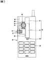
図1は本発明の第1実施形態による携帯端末機の斜視図であり、図2は本発明の第1実施形態による携帯端末機の分解斜視図であり、図3は本発明の第1実施形態による携帯端末機の正面図である。 FIG. 1 is a perspective view of a portable terminal according to a first embodiment of the present invention, FIG. 2 is an exploded perspective view of the portable terminal according to the first embodiment of the present invention, and FIG. 3 is a first embodiment of the present invention. It is a front view of the portable terminal by a form.
図1〜図3に示すように、本発明の第1実施形態による携帯端末機は、各種の情報を表示するディスプレイ12及びサウンドを送出するスピーカ14が取り付けられる第1本体10と、第1本体10がスライド可能に装着され、前面にユーザが情報を入力するキーパッド22が取り付けられ、背面にバッテリ24が取り付けられる第2本体20と、第1本体10と第2本体20との間に設置され、第1本体10を開方向に付勢する弾性力提供部と、第1本体10と第2本体20との間に設置され、第1本体10が閉状態のとき、第1本体10をロックするロックユニット40と、第1本体10のスライド時に発生する衝撃が低減するようにダンピング動作を行うダンピングユニット60とから構成される。
As shown in FIGS. 1 to 3, the mobile terminal according to the first embodiment of the present invention includes a first
前記弾性力提供部は、第2本体20の前面に長手方向に形成されるガイド溝32と、第1本体10の背面に固定され、ガイド溝32に沿って移動する移動ロッド34と、ガイド溝32と移動ロッド34との間に設置されて移動ロッド34を付勢する弾性部材36とから構成される。
The elastic force providing unit includes a
このような弾性力提供部は、ロックユニット40のロックが解除されると、弾性部材36の弾性力により、移動ロッド34がガイド溝32に沿ってスライドし、これにより、移動ロッド34が固定された第1本体10が開方向にスライドされる。
In such an elastic force providing unit, when the
ロックユニット40は、第2本体20の側面に外部に露出した状態で配設されるボタン42と、ボタン42に連結されて、ボタン42が押されることによって直線移動するプッシュロッド44と、第1本体10に固定され、第2本体20の前面に形成されたガイドスロット46に沿って移動し、プッシュロッド44に係止される係止ロッド48と、プッシュロッド44に取り付けられ、ボタン42を押された状態から元の状態に復帰させるリターンスプリング50とから構成される。
The
係止ロッド48は、第1本体10に形成された固定溝54に締結される固定ブラケット52の一面から垂直方向に突出し、その一面は直角に形成されてプッシュロッド44に係止され、他面には傾斜面が形成されて第1本体10の閉方向へのスライド時に係止されないようにする。
The locking rod 48 projects vertically from one surface of the fixing
このようなロックユニット40においては、ボタン42を押すと、プッシュロッド44が直線移動して係止ロッド48から離脱してロックが解除される。すると、第1本体10は、弾性部材36の弾性力により自動で開方向にスライドされる。
In such a
ダンピングユニット60は、移動ロッド34の一側面に長手方向に形成されるラックギア62と、ラックギア62に噛み合って移動ロッド34の直線移動により回転運動するピニオンギア64と、第2本体20に固定されてピニオンギア64が取り付けられて、ピニオンギア64が徐々に回転するようにダンピングするダンパ66とから構成される。
The damping unit 60 is fixed to the
ダンパ66は、図4に示すように、第2本体20に固定されてその内部に流体が充填されるダンパハウジング70と、ダンパハウジング70の内部に回転可能に配設され、流体の通過時に流動抵抗を発生させるオリフィス72が形成される複数の回転翼74と、回転翼74及びピニオンギア64が固定される回転軸76とから構成される。
As shown in FIG. 4, the
このようなダンピングユニット60においては、ラックギア62に噛み合ったピニオンギア64が回転すると、回転軸76が回転して回転翼74が回転し、これにより、回転翼74に形成されたオリフィス72が流体の通過時に流動抵抗を発生させてダンピング力を発生させる。
In such a damping unit 60, when the
以下、このように構成された本発明の第1実施形態による携帯端末機の動作を説明する。 Hereinafter, the operation of the mobile terminal according to the first embodiment of the present invention configured as described above will be described.
図5は本発明の第1実施形態による携帯端末機の作動状態図である。 FIG. 5 is an operational state diagram of the mobile terminal according to the first embodiment of the present invention.
第1本体10が閉状態のときは、ロックユニット40の係止ロッド48がプッシュロッド44に係止された状態になって、端末機が閉状態を維持する。このとき、第2本体20に配設された弾性部材36は圧縮された状態になる。
When the first
このような状態で、ユーザが端末機を使用するためにボタン42を押すと、プッシュロッド44が直線移動して係止ロッド48から離脱して、第1本体10のロックを解除させる。すると、弾性部材36の弾性力により、移動ロッド34がガイド溝32に沿って直線移動し、これにより、移動ロッド34が固定された第1本体10が開方向にスライドされる。
In such a state, when the user presses the
このとき、移動ロッド34に形成されたラックギア62に噛み合ったピニオンギア64が回転するが、ピニオンギア64に取り付けられたダンピングユニット60のダンピング動作により、ピニオンギア64は徐々に回転し、これにより、移動ロッド34が徐々に移動して、第1本体10が開くときに発生する衝撃を緩和させる。
At this time, the
ダンピングユニット60の動作を説明すると、ピニオンギア64が回転すると、ピニオンギア64が固定された回転軸76が回転し、回転軸76の回転により回転翼74が回転して、ハウジング70に充填された流体が回転翼74に形成されたオリフィス72を通過することによって、流動抵抗が発生し、ピニオンギア64が徐々に回転する。
The operation of the damping unit 60 will be described. When the
図6は本発明の第2実施形態によるスライドモジュールの斜視図である。 FIG. 6 is a perspective view of a slide module according to a second embodiment of the present invention.
本発明の第2実施形態によるスライドモジュールは、第1本体10に固定される第1スライド部材80と、第2本体20に固定され、第1スライド部材80がスライド可能に取り付けられる第2スライド部材82と、第1スライド部材80と第2スライド部材88との間に設置され、第1スライド部材80の開方向又は閉方向へのスライド時に弾性力を提供する弾性力提供部(図示せず)と、第1スライド部材80と第2スライド部材82との間に設置され、第1スライド部材80の開方向又は閉方向へのスライド時に発生する衝撃を吸収するダンピングユニット86とから構成される。
The slide module according to the second embodiment of the present invention includes a
第1スライド部材80の両側面には、ガイドロッド88が長手方向に取り付けられ、第2スライド部材82の両側面には、ガイドロッド88が挿入されて直線移動するガイドホール90が形成される。
前記弾性力提供部は、その一側が第1スライド部材80に固定され、その他側は第2スライド部材82に固定されて、第1スライド部材80を開方向又は閉方向に押して第1スライド部材80が死点を通過すると第1スライド部材80を付勢するもので、いかなる構造も適用可能である。
One side of the elastic force providing part is fixed to the
ダンピングユニット86は、第1スライド部材80と第2スライド部材82との間に設置され、第1スライド部材80のスライド時に回転する回転部92、94と、回転部92、94に設置されて回転部92、94の回転時にダンピング力を発生させるダンパ66とから構成される。
The damping unit 86 is installed between the
回転部92、94は、第1スライド部材80に固定されて第1スライド部材80と共に直線移動するラックギア94と、ラックギア94に噛み合ってダンパ66が設置されるピニオンギア92とから構成される。
The rotating parts 92, 94 are constituted by a rack gear 94 fixed to the
ダンパ66は、第2スライド部材82に固定され、ピニオンギア92が回転可能に取り付けられて、ピニオンギア92の回転時にダンピング力を発生させるもので、前述した一実施形態で説明したダンパ99と同一構造であるので、その説明を省略する。
The
このように構成された本発明の第2実施形態による携帯端末機は、第1本体10に固定された第1スライド部材80が開方向又は閉方向にスライドされると、弾性力提供部が第1スライド部材80を付着して、第1スライド部材80が自動でスライドされる。
In the portable terminal according to the second embodiment of the present invention configured as described above, when the
このとき、ダンピングユニット86のダンピング動作により、第1スライド部材80が徐々にスライドされて、第1スライド部材80のスライド時に発生する衝撃が低減する。
At this time, the
より詳細に説明すると、第1スライド部材80がスライドされると、第1スライド部材80に取り付けられたラックギア94が直線移動し、これにより、ラックギア94に噛み合ったピニオンギア92が回転し、ピニオンギア92が取り付けられたダンパ66がピニオンギア92の回転力を減衰させて、第1スライド部材80が徐々にスライドされる。
More specifically, when the
以上のように、本発明の好ましい実施形態を用いて本発明を例示してきたが、本発明は、この実施形態に限定して解釈されるべきものではない。本発明は、特許請求の範囲によってのみその範囲が解釈されるべきであることが理解される。当業者は、本発明の具体的な好ましい実施形態の記載から、本発明の記載および技術常識に基づいて等価な範囲を実施することができることが理解される。 As mentioned above, although this invention has been illustrated using preferable embodiment of this invention, this invention should not be limited and limited to this embodiment. It is understood that the scope of the present invention should be construed only by the claims. It is understood that those skilled in the art can implement an equivalent range from the description of specific preferred embodiments of the present invention based on the description of the present invention and common general technical knowledge.
端末機にダンピングユニットを設置して、端末機の開閉時にダンピング動作を行うことにより、端末機の開閉時に発生する衝撃を低減できる携帯端末機を提供する。 Provided is a portable terminal capable of reducing impact generated when a terminal is opened and closed by installing a damping unit in the terminal and performing a damping operation when the terminal is opened and closed.
携帯端末機は、第1本体と、第1本体が開閉可能に装着される第2本体と、第1本体と第2本体との間に設置され、第1本体の開閉時に弾性力を提供する弾性力提供部と、第1本体と第2本体との間に設置され、第1本体の開閉時に発生する衝撃を低減するダンピングユニットとを含む。 The portable terminal is installed between the first main body, the second main body on which the first main body can be opened and closed, and between the first main body and the second main body, and provides an elastic force when the first main body is opened and closed. An elastic force providing unit and a damping unit that is installed between the first main body and the second main body and that reduces an impact generated when the first main body is opened and closed are included.
10 第1本体
20 第2本体
32 ガイド溝
34 移動ロッド
40 ロックユニット
42 ボタン
44 プッシュロッド
46 ガイドスロット
48 係止ロッド
50 リターンスプリング
60 ダンピングユニット
62 ラックギア
64 ピニオンギア
66 ダンパ
DESCRIPTION OF
Claims (4)
前記第1本体が開閉可能に装着され、長手方向にガイドスロットが形成される第2本体と、
前記第1本体と前記第2本体との間に設置され、前記第1本体の開閉時に弾性力を提供する弾性力提供部と、
前記第1本体と前記第2本体との間に設置され、前記第1本体の開閉時に発生する衝撃を低減するダンピングユニットと、
前記第1本体と前記第2本体との間に設置され、前記第1本体が閉状態のとき、前記第1本体をロックするロックユニットとを含み、
前記ロックユニットは、
前記第2本体に固定され、直線移動可能に形成されるプッシュロッドと、
前記第1本体に固定され、前記プッシュロッドに係止され、前記係止の解除により前記ガイドスロットに沿って移動するように、前記第1本体から前記ガイドスロットに向かって突出し、前記プッシュロッドが移動する面を貫通して前記ガイドスロットに挿入される係止ロッドとを含み、
前記弾性力提供部は、
前記第2本体に長手方向に形成され、前記ガイドスロットと平行をなすガイド溝と、
前記ガイドスロットと平行に形成され、前記第1本体の背面に固定され、前記ガイド溝に移動可能に配設される移動ロッドと、
前記ガイド溝と前記移動ロッドとの間に設置されて前記移動ロッドを付勢する弾性部材とから構成され、
前記ダンピングユニットは、
前記移動ロッドの一側面に長手方向に形成されるラックギアと、
前記ラックギアに噛み合うピニオンギアと、
前記第2本体に固定されて前記ピニオンギアに連結されて、前記ピニオンギアが徐々に回転するようにダンピングするダンパと、
から構成されることを特徴とする携帯端末機。 A first body;
A second body on which the first body is detachably mounted and a guide slot is formed in a longitudinal direction;
An elastic force providing unit that is installed between the first main body and the second main body and provides an elastic force when the first main body is opened and closed;
A damping unit that is installed between the first main body and the second main body and reduces an impact generated when the first main body is opened and closed;
A locking unit that is installed between the first body and the second body, and locks the first body when the first body is in a closed state;
The lock unit is
A push rod fixed to the second body and formed to be linearly movable;
The push rod is fixed to the first body, locked to the push rod, and protrudes from the first body toward the guide slot so as to move along the guide slot when the lock is released. A locking rod that passes through the moving surface and is inserted into the guide slot ;
The elastic force providing unit is:
A guide groove formed in the second body in a longitudinal direction and parallel to the guide slot;
A moving rod formed in parallel with the guide slot, fixed to the back surface of the first body, and movably disposed in the guide groove;
An elastic member that is installed between the guide groove and the moving rod and biases the moving rod;
The damping unit is
A rack gear formed in a longitudinal direction on one side of the moving rod;
A pinion gear meshing with the rack gear;
A damper fixed to the second main body and coupled to the pinion gear so as to cause the pinion gear to gradually rotate;
A mobile terminal characterized by comprising:
前記第2本体に設置されるボタンをさらに含み、
前記プッシュロッドが、前記ボタンに連結されて、前記ボタンが押されることによって直線移動するように形成されることを特徴とする請求項1に記載の携帯端末機。 The lock unit is
A button installed on the second body;
The mobile terminal according to claim 1, wherein the push rod is connected to the button and linearly moves when the button is pressed.
前記第2本体に形成された装着部に固定されて内部に流体が充填されるハウジングと、
前記ハウジングに回転可能に配設されて前記ピニオンギアが連結される回転軸と、
前記回転軸の外周面に等間隔に配設され、流体の通過時に流動抵抗を発生させるオリフィスが形成される回転翼と、
から構成されることを特徴とする請求項1に記載の携帯端末機。 The damper is
A housing fixed to a mounting portion formed in the second body and filled with a fluid;
A rotating shaft rotatably disposed on the housing and connected to the pinion gear;
A rotary vane that is arranged on the outer peripheral surface of the rotary shaft at equal intervals, and that is formed with an orifice that generates flow resistance when the fluid passes;
The mobile terminal according to claim 1 , comprising:
Applications Claiming Priority (1)
| Application Number | Priority Date | Filing Date | Title |
|---|---|---|---|
| KR1020050061381A KR100677474B1 (en) | 2005-07-07 | 2005-07-07 | Slide type mobile communication terminal |
Publications (2)
| Publication Number | Publication Date |
|---|---|
| JP2007020180A JP2007020180A (en) | 2007-01-25 |
| JP4533868B2 true JP4533868B2 (en) | 2010-09-01 |
Family
ID=37081601
Family Applications (1)
| Application Number | Title | Priority Date | Filing Date |
|---|---|---|---|
| JP2006186108A Expired - Fee Related JP4533868B2 (en) | 2005-07-07 | 2006-07-05 | Portable terminal |
Country Status (7)
| Country | Link |
|---|---|
| US (1) | US20070010284A1 (en) |
| EP (1) | EP1742448B1 (en) |
| JP (1) | JP4533868B2 (en) |
| KR (1) | KR100677474B1 (en) |
| CN (1) | CN1893459A (en) |
| AT (1) | ATE469502T1 (en) |
| DE (1) | DE602006014474D1 (en) |
Families Citing this family (13)
| Publication number | Priority date | Publication date | Assignee | Title |
|---|---|---|---|---|
| KR100819284B1 (en) * | 2007-03-13 | 2008-04-03 | 삼성전자주식회사 | Portable terminal with sliding module |
| KR100856238B1 (en) * | 2007-03-20 | 2008-09-03 | 삼성전자주식회사 | Sliding type portable terminal |
| JP4649453B2 (en) * | 2007-09-12 | 2011-03-09 | シャープ株式会社 | Sliding mobile terminal |
| JP4649454B2 (en) * | 2007-09-12 | 2011-03-09 | シャープ株式会社 | Sliding mobile terminal |
| CN101562641B (en) * | 2008-04-16 | 2012-03-14 | 深圳富泰宏精密工业有限公司 | Sliding closure structure and portable type electronic device using the sliding closure structure |
| TWI418201B (en) * | 2008-05-30 | 2013-12-01 | Fih Hong Kong Ltd | Rotatable mechanism and a portable electronic device using the same |
| CN101750698A (en) * | 2008-12-10 | 2010-06-23 | 深圳富泰宏精密工业有限公司 | Lens module and electronic device applying lens module |
| CN101764859B (en) * | 2008-12-23 | 2013-06-05 | 鸿富锦精密工业(深圳)有限公司 | Electronic device |
| TWI413478B (en) * | 2009-01-09 | 2013-10-21 | Hon Hai Prec Ind Co Ltd | Electronic device |
| CN102724825B (en) * | 2011-03-30 | 2015-06-03 | 宏达国际电子股份有限公司 | Portable electronic apparatus |
| EP2525114B1 (en) * | 2011-05-20 | 2013-06-26 | Research In Motion Limited | Low profile rotary damper |
| US8540062B2 (en) | 2011-05-20 | 2013-09-24 | Research In Motion Limited | Low profile rotary damper |
| CN110786082A (en) * | 2018-11-30 | 2020-02-11 | 深圳市大疆创新科技有限公司 | Remote controller and remote control system |
Citations (3)
| Publication number | Priority date | Publication date | Assignee | Title |
|---|---|---|---|---|
| JP2004222173A (en) * | 2003-01-17 | 2004-08-05 | Matsushita Electric Ind Co Ltd | Portable telephone set |
| JP2004328201A (en) * | 2003-04-23 | 2004-11-18 | Nifco Inc | Slide unit for mobile terminal machine |
| JP2005167847A (en) * | 2003-12-04 | 2005-06-23 | Toyoda Gosei Co Ltd | Mobile communication terminal |
Family Cites Families (8)
| Publication number | Priority date | Publication date | Assignee | Title |
|---|---|---|---|---|
| GB2353170A (en) * | 1999-08-06 | 2001-02-14 | Nokia Mobile Phones Ltd | Slide assembly for a communication unit |
| US6980840B2 (en) * | 2000-01-24 | 2005-12-27 | Lg Electronics Inc. | Drawer-type mobile phone |
| FI112422B (en) | 2000-04-28 | 2003-11-28 | Nokia Corp | Telescopic structure for telephone equipment |
| KR100484732B1 (en) * | 2002-11-19 | 2005-04-22 | 삼성전자주식회사 | Sliding type portable wireless terminal |
| US7283852B2 (en) | 2003-09-10 | 2007-10-16 | Nokia Corporation | Movable functional elements for mobile communication device |
| KR100617690B1 (en) * | 2003-11-10 | 2006-08-28 | 삼성전자주식회사 | Sliding type portable wireless terminal |
| TWM260061U (en) * | 2004-06-11 | 2005-03-21 | Quanta Comp Inc | Automatic sliding mechanism |
| TWM261971U (en) * | 2004-06-17 | 2005-04-11 | Quanta Comp Inc | Damping sliding rail |
-
2005
- 2005-07-07 KR KR1020050061381A patent/KR100677474B1/en not_active IP Right Cessation
-
2006
- 2006-07-05 JP JP2006186108A patent/JP4533868B2/en not_active Expired - Fee Related
- 2006-07-06 AT AT06014056T patent/ATE469502T1/en not_active IP Right Cessation
- 2006-07-06 EP EP06014056A patent/EP1742448B1/en not_active Not-in-force
- 2006-07-06 DE DE602006014474T patent/DE602006014474D1/en active Active
- 2006-07-07 CN CNA200610101324XA patent/CN1893459A/en active Pending
- 2006-07-07 US US11/482,307 patent/US20070010284A1/en not_active Abandoned
Patent Citations (3)
| Publication number | Priority date | Publication date | Assignee | Title |
|---|---|---|---|---|
| JP2004222173A (en) * | 2003-01-17 | 2004-08-05 | Matsushita Electric Ind Co Ltd | Portable telephone set |
| JP2004328201A (en) * | 2003-04-23 | 2004-11-18 | Nifco Inc | Slide unit for mobile terminal machine |
| JP2005167847A (en) * | 2003-12-04 | 2005-06-23 | Toyoda Gosei Co Ltd | Mobile communication terminal |
Also Published As
| Publication number | Publication date |
|---|---|
| JP2007020180A (en) | 2007-01-25 |
| EP1742448B1 (en) | 2010-05-26 |
| US20070010284A1 (en) | 2007-01-11 |
| KR20070006236A (en) | 2007-01-11 |
| EP1742448A1 (en) | 2007-01-10 |
| DE602006014474D1 (en) | 2010-07-08 |
| ATE469502T1 (en) | 2010-06-15 |
| KR100677474B1 (en) | 2007-02-02 |
| CN1893459A (en) | 2007-01-10 |
Similar Documents
| Publication | Publication Date | Title |
|---|---|---|
| JP4533868B2 (en) | Portable terminal | |
| JP4302708B2 (en) | Slide-type mobile terminal | |
| US7650671B2 (en) | Slide hinge module and slide type equipment utilizing the same | |
| JP5252677B2 (en) | Portable terminal | |
| JP2007116709A (en) | Slide module and mobile terminal incorporating the slide module | |
| US7564967B2 (en) | Electronic device with two-dimensional sliding cover and two-dimensional slide apparatus | |
| US20060154515A1 (en) | Sliding module for portable terminal | |
| JPWO2008120706A1 (en) | Mobile device slide structure and mobile device | |
| US20090241292A1 (en) | Hinge assembly and computer housing using the same | |
| JP2010074741A (en) | Slide type small-size electronic device | |
| US8996079B2 (en) | Portable terminal with multiple-hinges | |
| JP4297493B2 (en) | Lid opening / closing mechanism and apparatus therefor | |
| JPH0711836A (en) | Folding doors | |
| JP4619343B2 (en) | Foldable mobile terminal | |
| KR101009933B1 (en) | Hinge apparatus of folder type portable terminal | |
| KR20090124036A (en) | Slide apparatus | |
| JP5026399B2 (en) | Electronics | |
| JP5457589B2 (en) | Sliding small electronic equipment | |
| JP2010103998A (en) | Slide hinge module for mobile phone with built-in keypad | |
| JP5466931B2 (en) | Portable electronic devices | |
| TWI425805B (en) | Sliding cell phone structure | |
| KR101107121B1 (en) | Folder type electronic apparatus | |
| KR100713375B1 (en) | Sliding module for portable terminal | |
| JP2010034803A (en) | Mobile terminal | |
| JP4742369B2 (en) | Portable information terminal device |
Legal Events
| Date | Code | Title | Description |
|---|---|---|---|
| A977 | Report on retrieval |
Free format text: JAPANESE INTERMEDIATE CODE: A971007 Effective date: 20090108 |
|
| A131 | Notification of reasons for refusal |
Free format text: JAPANESE INTERMEDIATE CODE: A131 Effective date: 20090119 |
|
| A521 | Request for written amendment filed |
Free format text: JAPANESE INTERMEDIATE CODE: A523 Effective date: 20090227 |
|
| A131 | Notification of reasons for refusal |
Free format text: JAPANESE INTERMEDIATE CODE: A131 Effective date: 20091002 |
|
| A521 | Request for written amendment filed |
Free format text: JAPANESE INTERMEDIATE CODE: A523 Effective date: 20091201 |
|
| TRDD | Decision of grant or rejection written | ||
| A01 | Written decision to grant a patent or to grant a registration (utility model) |
Free format text: JAPANESE INTERMEDIATE CODE: A01 Effective date: 20100521 |
|
| A01 | Written decision to grant a patent or to grant a registration (utility model) |
Free format text: JAPANESE INTERMEDIATE CODE: A01 |
|
| A61 | First payment of annual fees (during grant procedure) |
Free format text: JAPANESE INTERMEDIATE CODE: A61 Effective date: 20100614 |
|
| R150 | Certificate of patent or registration of utility model |
Free format text: JAPANESE INTERMEDIATE CODE: R150 |
|
| FPAY | Renewal fee payment (event date is renewal date of database) |
Free format text: PAYMENT UNTIL: 20130618 Year of fee payment: 3 |
|
| R250 | Receipt of annual fees |
Free format text: JAPANESE INTERMEDIATE CODE: R250 |
|
| R250 | Receipt of annual fees |
Free format text: JAPANESE INTERMEDIATE CODE: R250 |
|
| R250 | Receipt of annual fees |
Free format text: JAPANESE INTERMEDIATE CODE: R250 |
|
| R250 | Receipt of annual fees |
Free format text: JAPANESE INTERMEDIATE CODE: R250 |
|
| R250 | Receipt of annual fees |
Free format text: JAPANESE INTERMEDIATE CODE: R250 |
|
| LAPS | Cancellation because of no payment of annual fees |