JP4532653B2 - Encoding method and apparatus - Google Patents
Encoding method and apparatus Download PDFInfo
- Publication number
- JP4532653B2 JP4532653B2 JP2000069353A JP2000069353A JP4532653B2 JP 4532653 B2 JP4532653 B2 JP 4532653B2 JP 2000069353 A JP2000069353 A JP 2000069353A JP 2000069353 A JP2000069353 A JP 2000069353A JP 4532653 B2 JP4532653 B2 JP 4532653B2
- Authority
- JP
- Japan
- Prior art keywords
- coefficients
- block
- dwt
- level
- subband
- Prior art date
- Legal status (The legal status is an assumption and is not a legal conclusion. Google has not performed a legal analysis and makes no representation as to the accuracy of the status listed.)
- Expired - Fee Related
Links
Images


Classifications
-
- H—ELECTRICITY
- H04—ELECTRIC COMMUNICATION TECHNIQUE
- H04N—PICTORIAL COMMUNICATION, e.g. TELEVISION
- H04N19/00—Methods or arrangements for coding, decoding, compressing or decompressing digital video signals
- H04N19/60—Methods or arrangements for coding, decoding, compressing or decompressing digital video signals using transform coding
- H04N19/63—Methods or arrangements for coding, decoding, compressing or decompressing digital video signals using transform coding using sub-band based transform, e.g. wavelets
- H04N19/635—Methods or arrangements for coding, decoding, compressing or decompressing digital video signals using transform coding using sub-band based transform, e.g. wavelets characterised by filter definition or implementation details
-
- H—ELECTRICITY
- H04—ELECTRIC COMMUNICATION TECHNIQUE
- H04N—PICTORIAL COMMUNICATION, e.g. TELEVISION
- H04N19/00—Methods or arrangements for coding, decoding, compressing or decompressing digital video signals
- H04N19/60—Methods or arrangements for coding, decoding, compressing or decompressing digital video signals using transform coding
- H04N19/63—Methods or arrangements for coding, decoding, compressing or decompressing digital video signals using transform coding using sub-band based transform, e.g. wavelets
- H04N19/64—Methods or arrangements for coding, decoding, compressing or decompressing digital video signals using transform coding using sub-band based transform, e.g. wavelets characterised by ordering of coefficients or of bits for transmission
- H04N19/645—Methods or arrangements for coding, decoding, compressing or decompressing digital video signals using transform coding using sub-band based transform, e.g. wavelets characterised by ordering of coefficients or of bits for transmission by grouping of coefficients into blocks after the transform
-
- H—ELECTRICITY
- H04—ELECTRIC COMMUNICATION TECHNIQUE
- H04N—PICTORIAL COMMUNICATION, e.g. TELEVISION
- H04N19/00—Methods or arrangements for coding, decoding, compressing or decompressing digital video signals
- H04N19/42—Methods or arrangements for coding, decoding, compressing or decompressing digital video signals characterised by implementation details or hardware specially adapted for video compression or decompression, e.g. dedicated software implementation
Description
【0001】
【発明の属する技術分野】
本発明は、デジタル画像圧縮分野、特に画像のウエーブレット分解を実行する符号化方法および装置に関する。
【0002】
【従来の技術】
デジタル・データ圧縮、および特にデジタル画像圧縮の分野は、一時非常に注目されていたが、特に最近、離散ウエーブレット変換(DWT) に基づく圧縮技術がますます一般的になってきている。これはDWTが画像の非冗長階層的分解を提供し、また、画像の圧縮結果が良好な定歪み統計値を提供するからである。
【0003】
一般的に、画像の離散ウエーブレット変換(DWT) は、一連の一次元DWTを用いて実行される。信号(すなわち、画像の行)の一次元DWTが、ロウパスおよびハイパスフィルタリングされ、各フィルタされた信号を2つおきに選んで実行される。この2つおきに取り出すのは、フィルタリング処理されたサンプルを2つおきに計算して保持することを意味する。たたみこみ(フィルタリング)が実行されると、フィルタは、普通は一つのサンプルであるのとは代わって、一度に二つのサンプル毎に進行する。この方法において、N個のサンプルの信号に対して、N個のDWTのサンプル、すなわち、実質的にN/2のロウパス・サンプルと実質的にN/2のハイパス・サンプルがある。
【0004】
【発明が解決しようとする課題】
これはランダム・アクセス・メモリ(RAM)のようなコンピュータ・メモリ内で全画像をバッファリングすることによって実行されるのが一般的で、バッファされた画像にDWTが実行され、その変換された画像が符号化される。あいにく、このアプローチには大量のメモリ、特に2000画素×2000画素或いはそれ以上を必要とし、十分な処理速度を達成しなければならない場合には、相当なバンド幅を必要とする。
【0005】
本発明は上記従来例に鑑みてなされたもので、本発明の目的は、既存の構成の一つのまたはそれ以上の欠点を実質上克服するか、ないしは少なくともこれを改善することにある。例えば、少ないバッファの容量で、複数レベルのDWT実行できる構成を提供する。
【0006】
【課題を解決するための手段】
本発明の第1の態様によれば、離散ウエーブレット変換(DWT)により変換して所定レベルに分解され、各ブロックが一次元および二次元における係数による特定ブロック・サイズを有するブロック単位で符号化できる複数の画素を含むデジタル画像を符号化する方法を提供することにあり、この方法は、
a)画像を複数のタイルに分割する工程であって、各タイルが、DWT分解の前記所定レベルで前記ブロックの一次元における係数を発生するのに必要とされる画素の最小数を有し、またDWT分解の前記所定レベルで前記ブロックのニ次元における係数を発生するのに必要とされる画素の最小数より少ない数を有し、1回のDWT分解で得られるLH,HL,HHから前記特定のブロックサイズのブロックを形成できる画素数を有するように、画像を複数のタイルに分割する工程と;
b)前記複数のタイルの中から、DWT分解の対象となる処理対象タイルを選択する工程と;
c)DWTを使用して前記処理対象タイルをDWT分解の少なくとも一つのレベルに分解してLL、LH、HLおよびHHサブバンドを含む複数のサブバンドを形成する工程と;
d)LH、HLおよびHHサブバンドの各サブバンド内の係数を蓄積して前記特定のブロックサイズのブロックを形成するとともに、各ブロックをビットストリームに符号化する工程と;
e)前記LLサブバンドの係数を蓄積するとともに、当該LLサブバンドの所定数の係数が蓄積されるまで、前記工程b)からe)を繰り返す工程と;
f)前記処理対象タイルとして、蓄積されたLLサブバンドの前記所定数の係数を割り当てる工程と;
g)前記DWT分解の前記所定レベルに達するまで、前記工程c)からg)を繰り返す工程と;
h)前記LLサブバンドをビットストリームに符号化する工程と;
を含んでいる。
【0007】
本発明の第2の態様によれば、
離散ウエーブレット変換(DWT)により変換して所定レベルに分解でき、かつ各ブロックが一次元および二次元の複数の係数を含む特定のブロックサイズを有しブロック単位で符号化される複数の画素を含むデジタル画像を符号化する符号化方法であって、
a)各タイルがDWT分解の前記所定レベルで前記ブロックの一次元における係数を発生するのに必要とされる画素の最小数を有し、また、DWT分解の前記所定レベルで前記ブロックの一次元における係数を発生するのに必要とされる画素の最小数より少ない数を有し、1回のDWT分解で得られるLH,HL,HHから前記特定のブロックサイズのブロックを形成できる画素数を有するように、画像を複数のタイルに分割する工程と、;
b)前記複数のタイルの中から、DWT分解の対象となる処理対象タイルを選択する工程と;
c)DWTを使用して前記処理対象タイルをLL、LH、HLおよびHHサブバンドの複数の係数を提供するように分解する工程と;
d)前記工程(c)で得られた現在レベルのLH、HL、HHサブバンドの係数をビットストリームに符号化する工程と;
e)前記現在レベルが前記所定レベルであるかどうかを判定し:
ea)前記現在レベルが前記所定レベルであれば、前記LLサブバンドの係数をビットストリームに符号化し、前記工程b)からe)を繰り返し;
eb)前記現在レベルが前記所定レベルでなければ、前記LLサブバンドの前回符号化されていない係数を記憶する工程と;
f)前記現在レベルにおける前記LLサブバンドの前記記憶された係数が少なくとも所定数であるかどうかを判定する工程と;
fa)前記記憶されたLL係数が少なくとも前記所定数であれば、処理対象タイルとして前記係数の前記所定数を処理対象タイルに割り当て、前記工程c)からf)を繰り返す工程と;
fb)記憶された前記係数の数が前記所定数より少なければ、前記工程b)からf)を繰り返す工程と;
を含む符号化方法が提供される。
【0008】
本発明の第3の態様によれば、
離散ウエーブレット変換(DWT)により変換して所定レベルに分解でき、かつ各ブロックが一次元および二次元の複数の係数を含む特定のブロックサイズを有しブロック単位で符号化される複数の画素を含むデジタル画像を符号化する符号化装置であって、
a)各タイルが、DWT分解の前記所定レベルで前記ブロックの一次元における係数を発生するのに必要とされる画素の最小数を有し、またDWT分解の前記所定レベルで前記ブロックの二次元における係数を発生するのに必要とされる画素の最小数より少ない数を有し、1回のDWT分解で得られるLH,HL,HHから前記特定のブロックサイズのブロックを形成できる画素数を有するように、画像を複数のタイルに分割する手段;
b)前記複数のタイルの中から、DWT分解の対象となる処理対象タイルを選択する選択手段と;
c)DWTを使用して、前記処理対象タイルをDWT分解の少なくとも一つのレベルに分解してLL、LH、HLおよびHHサブバンドを含む複数のサブバンドを形成する分解手段と;
d)前記LLサブバンド係数の所定数を蓄積する手段と;
e)蓄積された前記係数の前記所定数を処理対象タイルとして割り当てる手段と;
f)前記処理対象タイルをさらなるレベルの分解度に分解するために処理対象タイルを前記分解手段に帰還させる手段と;
g)LH、HLおよびHHサブバンドの各サブバンド内の係数を蓄積して前記特定のブロックサイズのブロックを形成するとともに、前記所定レベルでLLサブバンド内の前記特定のブロックサイズの少なくとも一つのブロックを蓄積する手段と;
h)各前記ブロックをビットストリームに符号化する符号化手段と;
を有することを特徴とする符号化装置が提供される。
【0009】
本発明の第4の態様によれば、
離散ウエーブレット変換(DWT)により変換して所定レベルに分解でき、かつ各ブロックが一次元および二次元の複数の係数を含む特定のブロックサイズを有しブロック単位で符号化される複数の画素を含むデジタル画像を符号化する符号化装置であって、
各画像の部分がDWT分解の前記所定レベルで前記ブロックの一次元における係数を発生するのに必要とされる画素の最小数を有し、また、DWT分解の前記所定レベルで前記ブロックの二次元における係数を発生するのに必要とされる画素の最小数より少ない数を有し、1回のDWT分解で得られるLH,HL,HHから前記特定のブロックサイズのブロックを形成できる画素数を有するように、前記画像の少なくとも一部を記憶する手段と;
リニア変換を前記画像の前記一部の一次元および二次元それぞれに適用して、各サブバンドが少なくとも一つの係数を含むLL、LH、HLおよびHHサブバンドを提供する第1および第2フィルタ手段と;
LLサブバンドの係数を所定数蓄積し、前記第1および第2フィルタ手段によってリフィルタして次のレベル分解を達成するための画像部分として、蓄積された前記係数を使用する部分バンド記憶手段と;
LH,HLおよびHHサブバンド内の各レベルに対する前記特定のブロックサイズの前記ブロックを蓄積し、また前記所定レベルの分解レベルにおけるLLサブバンド内の前記特定のブロックサイズの前記ブロックを蓄積するためのサブバンド記憶手段と;
各蓄積ブロックをビットストリームに符号化する符号化手段と;
を具備する符号化装置が提供される。
【0010】
本発明の第5の態様によれば、
離散ウエーブレット変換(DWT)により変換して所定レベルに分解でき、かつ各ブロックが一次元および二次元の複数の係数を含む特定のブロックサイズを有しブロック単位で符号化される複数の画素を含むデジタル画像を符号化する装置のためのプログラムを記憶するコンピュータにより読取可能な記憶媒体において、前記プログラムは前記コンピュータに、
a)各タイルが、DWT分解の前記所定レベルで前記ブロックの一次元における係数を発生するのに必要とされる画素の最小数を有し、またDWT分解の前記所定レベルで前記ブロックの二次元における係数を発生するのに必要とされる画素の最小数より少ない数を有し、1回のDWT分解で得られるLH,HL,HHから前記特定のブロックサイズのブロックを形成できる画素数を有するように、画像を複数のタイルに分割する工程と、
b)前記複数のタイルの中から、DWT分解の対象となる処理対象タイルを選択する工程と、
c)DWTを使用して前記処理対象タイルをDWT分解の少なくとも一つのレベルに分解してLL、LH、HLおよびHHサブバンドを含む複数のサブバンドを形成する分解工程と、
d)LH、HLおよびHHサブバンドの各サブバンドの係数を蓄積して前記特定のブロックサイズのブロックを形成するとともに、各ブロックをビットストリームに符号化する工程と、
e)前記LLサブバンドの係数を蓄積するとともに、当該LLサブバンドの係数が所定数が蓄積されるまで、工程b)からe)を繰り返す工程と、
f)前記処理対象タイルに、蓄積されたLLサブバンドの前記係数の前記所定数を割り当てる割り当て工程と、
g)前記DWT分解の前記所定レベルに達するまで、工程c)からg)を繰り返す繰り返し工程と、
h)前記LLサブバンドをビットストリームに符号化する符号化工程と実行させるプログラムであることを特徴とする記憶媒体が提供される。
【0011】
本発明の第6の態様によれば、
離散ウエーブレット変換(DWT)により変換して所定レベルに分解でき、かつ各ブロックが一次元および二次元の複数の係数を含む特定のブロックサイズを有しブロック単位で符号化される複数の画素を含むデジタル画像を符号化する装置のためのプログラムを記憶するコンピュータにより読取可能な記憶媒体において、前記プログラムは前記コンピュータに、
a)各タイルが、DWT分解の前記所定レベルで前記ブロックの一次元における係数を発生するのに必要とされる画素の最小数を有し、またDWT分解の前記所定レベルで前記ブロックの二次元における係数を発生するのに必要とされる画素の最小数より少ない数を有し、1回のDWT分解で得られるLH,HL,HHから前記特定のブロックサイズのブロックを形成できる画素数を有するように、画像を複数のタイルに分割する工程と、
b)前記複数のタイルの中から、DWT分解の対象となる処理対象タイルを選択する選択工程と、
c)DWTを使用して前記処理対象タイルをLL、LH、HLおよびHHサブバンドの複数の係数を提供するように分解する工程と、
d)工程(c)で得られた現在レベルのLH、HL、HHサブバンドの係数をビットストリームに符号化する符号化工程と、
e)前記現在レベルが前記所定レベルであるかどうかを判定する判定工程と、
ea)前記現在レベルが前記所定レベルであれば、前記LLサブバンドの係数をビットストリームに符号化する工程と;工程b)からe)を繰り返す工程と;
eb)前記現在レベルが前記所定レベルでなければ、前記LLサブバンドの前回符号化されていない係数を記憶する記憶工程と;
f)前記現在レベルにおけるLLサブバンドの前記記憶された係数が、少なくとも所定数であるかどうかを判定する工程と;
fa)記憶された前記係数の数が少なくとも前記所定数であれば、処理対象タイルとして前記係数の前記所定数を割り当てる割当工程と;工程c)からf)を繰り返す工程と;
fb)記憶された前記係数の数が前記所定数より小さければ、工程b)からf)を繰り返す繰返工程と;
を実行させるプログラムであることを特徴とする記憶媒体が提供される。
【0013】
【発明の実施の形態】
以下、添付図面を参照して本発明の好適な実施の形態を詳細に説明する。なお、添付図面のいずれか一つまたはそれ以上において、同じ工程および(または)特徴に同じ参照符号を付して参照するものとし、強調しない限り、これらの工程および(または)特徴は、この説明の目的としては、同じ機能または動作を有するのものである。
【0014】
図1を参照して、4レベルまでの画像の離散ウエーブレット分散を示す。最高レベルにおいて、すなわち、レベル4において、ロウ−ロウ(LL)周波数サブバンド(またはDCサブバンド)およびハイ−ロウ(HL4)周波数サブバンド、ロウ−ハイ(LH4)周波数サブバンドおよびハイ−ハイ(HH4)周波数サブバンドがある。次のレベルに下がると、そのレベルに対してハイ−ロウ(HL3)周波数サブバンド、ロウ−ハイ(LH3)周波数サブバンド、ロウ−ハイ(LH3)周波数サブバンドおよびハイ−ハイ(HH3)周波数サブバンドがある。また最低レベルにおいて、ハイ−ロウ(HL1)周波数サブバンド、ロウ−ハイ(LH1)周波数サブバンドおよびハイ−ハイ(HH1)周波数サブバンドがある。
【0015】
各レベルは、(単一レベル)離散ウエーブレット変換(DWT) の適用によって発生される。従って、DWTを画像へ適用することは、第1レベルのDCサブバンドと、それよりも3つ高い周波数サブバンドHL1、LH1およびHH1を発生することになる。こうして、DWTが第1レベルのDC(またはLL)サブバンドに適用されて、第2レベルのDCサブバンドと、それよりも3つ高い周波数サブバンドHL2、LH2およびHH2が発生される。次に、第2レベルのDCサブバンドに更にDWTを適用することにより、第三レベルのDCサブバンドと、それよりも3つ高いサブバンドHL3、LH3およびHH3などが発生され、所望のレベルに分解される。その結果、上述の四つのレベルの分解が、(単一レベル)DWTの4つの適用、すなわち、画像への第1の適用と、上述した再帰(回帰)方法により得られたロウ−ロウ(LL)周波数サブバンドへの後続の適用とを必要とする。
【0016】
本発明の好適な実施の形態は、メモリ効率(エフィシェント)と低メモリ・バンド幅(画素当りのバイト)を実現といった点で、所定のレベルの分解を達成する。好ましい実施の形態の更なる実施は、分解されるべき画像のサイズ(1K画素×1K画素より一般的に大きい画像に対して)とは実質上無関係である。すなわち、所定レベルにおける画像の離散ウエーブレット分解は、全画像を記憶するのに必要とする量よりも小さいメモリ容量で、また、画像の幅または高さとはほぼ無関係なメモリ・バッファによって提供される。
【0017】
本発明の好適な実施の形態は、DWT分解の最大レベル数を固定にし、分解されるべき画像を複数のタイルに分割し、また、各タイルの一次元が、DWT分解の最大レベルにおけるDCブロックの対応する(第1)次元の所定サイズDCブロックを生成するのに必要な略最小画素数となるように分割することによって、十分なメモリ・バッファと低メモリ・バンド幅を達成する。さらに、各タイルの二次元は、所定サイズのDCブロックの対応する(第2)次元を生成するのに必要とする略最小画素数より少ない。好ましくは、各タイルの二次元は、画素で測定した最小長さを有していることであり、これは最大レベルにおける所定サイズDCブロックの対応する次元の(フラクション)サブ−マルチプルを生成することを必要とされるからである。
【0018】
例えば、好ましい実施の形態によれば、Daubechies 9/7DWTフィルタ(すなわち、9タップ・ロウパスと7タップ・ハイパス)、および各レベルにおいて32係数×32係数(高さ×幅)のエントロピー符号化DWTブロック(アレイ)を使用して、各レベルにおいて、DWT分解の4レベルの最大まで、画像を複数のオーバラップするタイルにサブ分割する必要があり、各タイルは一次元(例えば、タイルの高さ)内で617画素となり、二次元(例えば、タイルの幅)内で71画素となる。各タイルは、分解の各反復において、ロウ−ロウ周波数部分の中間バッファリングにより4レベルにDWT分解され、所定数のDC係数が生成される。この種のタイルで約9回処理すると、DC係数の32×32ブロックがリカバーされ、エントロピー符号化される。各反復を通して、より高い周波数係数(例えば、各レベルにおけるHL、LHおよびHH)の32×32ブロックもエントロピー符号化される。
【0019】
次に、好ましい実施の形態につき、まず最初に、Daubechies 9/7DWTフィルタを使用する画像の4レベルDWT分解を参照し、続いてDWT係数の32×32ブロックのエントロピー符号化を説明するが、本発明はこれに限定されるものではない。ブロックのエントロピー符号化の前に、分解レベルの異なる所定最大数、異なるフィルタおよび/または蓄積された係数の異なるブロックサイズが、本発明の範囲と概念から逸脱することなしに使用することができる。例えば、5レベルDWT分解が実行でき、および/またはDWT係数の64×64ブロックを、1つのブロックのエントロピー符号化の前に蓄積することができる。さらに、多数のウエーブレット・フィルタが「HAAR」フィルタ、「LeGall 5/3」 「LeGall 10/18」を含めて使用することができる。この種の変形例により、次に説明するハードウエア・アーキテクチャを対応して変更してもよい。
【0020】
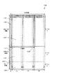
ここで、図2および図3を参照して、本発明の好適な実施の形態による画像のタイリングを示す。すなわち、好ましくは画像を部分的にオーバラップさせて、複数のタイルにサブ分割する。各タイルの大きさは、分解のレベル、エントロピー符号化の前に蓄積されたブロック・サイズ、および使用されるDWTフィルタの種類等の所定パラメータを固定することによって決定される。各タイルは、タイルの一つの次元の71画素に、他の次元の617画素を掛けたものからなる。図2において、タイルは水平方向に配置され、すなわち、タイルの長手側が画像の走査線と略平行にレイアウトされている。図3は、タイルが垂直方向に配置された別の構成を示しており、短手側が画像の走査線と略平行である。図2および図3の各タイルは、「タイルn」の符号が付けるられるが、ここでnは正の整数で、符号付け(ラベリング)は複数のタイルのうちの好ましい処理順序を示す。例えば、「タイル1」は「タイル2」の前に処理され、「タイル2」は「タイル3」の前に処理されるという具合である。さらに、各タイルは次に説明するように決定された近接のタイルと所定のオーバラップ域200と201を有している。
【0021】
一般的に、DWTの第2レベルにおいてサブバンドのHラインを生成するために、Daubechies 9/7DWTフィルタを使用して、LL1サブバンドの(2H+7)ラインが必要で、次に、これには画像の{2(2H+7)+7=4H+14+7}ラインが必要である。2Hラインに7ラインを付加することは、Daubechies 9/7DWTフィルタによって必要とされ、このことが「オーバラップ」200として表されている。好適には、このオーバラップは、処理されるべき2Hラインの前3ラインと、処理されるべき2Hラインの後4ラインとして分布されることである。
【0022】
数学的帰納法によれば、一つの次元において、いずれかのサブバンドのHラインを形成してレベルJにするには、
2J H+(2J-1 ・・+21 +20 )・7=2J H+7(2J −1) 式1
の画像ラインが必要である。上式の第2項が必要とされるオーバラップである。もちろん、これは他の次元に対しても同様に適用される。例えば、Daubechies 9/7フィルタを使用する4レベル分解(J=4)と、32画素幅(水平方向)W=32のブロックを蓄積するためには、式1によれば(16×32+7×15=512+105)幅のタイルを必要とし、ここでオーバラップ200は、105画素である。すなわち、図2中の「タイル1」と「タイル11」間のオーバラップ200は、水平方向の105画素に垂直方向の71画素(2H+7)を掛けたものである。
【0023】
本実施の形態では、一度に2H+7ラインを変換し、大きくなるラベル番号順に次の(オーバラップした)タイルを処理して、HL1、LH1およびHH1サブバンドの各々からHラインを生成する。これらのサブバンド部分は、このような画素(Hライン倍した)W(この例ではW=32画素)、すなわち、2H画素列が入力されると、上述した場合のように、直ちにコード化できる。タイルの第1パス(すなわち、一つの分解レベルにおける一つのタイル)の処理の終了時点において、LL1サブバンドの1ライン当たり{2J-1 W+7(2J-1 −1)}倍したHラインをバッファする必要がある。LL1サブバンドの1ライン当たりのこの係数値は、トップ・レベル(レベルJ)におけるW幅ブロックを形成するために必要である。図2において、タイル「タイル1」が処理された後、「タイル2」がほぼ同様にして処理される。すなわち、画像の他の{(2H+7)×(2JW+7(2J −1))}画素のタイルが処理される。ここで、「タイル2」が処理されると、LL1サブバンドの他のHラインが発生され、二つのタイルが処理された後、合計2Hラインとなる。LL1サブバンドをさらに分解してLL2サブバンドのHラインを生成するためには、LL1サブバンドの(2H+7)ラインが必要である。「タイル2」の処理後には、2Hラインが生成され、「タイル3」の処理後は、(2H+7)ラインを提供するための合計3Hを提供できる。これにより次のレベルの分解を実行してLL2サブバンドのHラインを生成する。即ち、各タイル毎にDWTを行い、LL1を生成するが、次のLL2を生成するために3つのタイルのLL1を用いて更にDWTを実行する。この方法によれば、小さいタイル単位(小さいバッファ容量)で2レベルのDWTが実行できる。同様にして、この方法を続行して少なくとも{2J H+7(2J −1)}ラインを処理すると、分解のJ番目のレベルにおける係数のHラインを生成することになる。即ち、レベル3(LL3)以降のLLnの作成のためにも、そのLLnの作成に必要な複数タイル分のLL(n−1)を利用することにより、HラインのLLjを最終的に生成する。ラインが{2J-1 W+7(2J-1 −1)}画素(またはDWT係数の長さ)であり、画像の幅または長さを必要としないことに注意されたい。次のレベルの分解を得るために各々の繰り返しにおいて、LL周波数のサブバンドの合成係数がバッファされ、他方で現在レベルにおいて発生されたより高い周波数(すなわち、LH、HL、HH)の各H×Wブロックが符号化のためにエントロピー符号化器に送られる。
【0024】
普通、出力デバイスおよび特に表示デバイスは、ラスタ走査順に、左から右へ、また、上から下へ画像を表示する。従って、本実施の形態の好ましい実施においては、図3に示したタイル配列となる。オーバラップするタイルは、タイルの最短次元が画像の走査ラインと平行になるように配列されるのが好ましい。好ましくは、タイルはタイルの次の列が処理される前に、画像の幅を横切って処理される。この配列は、タイルが左から右へ、また上から下へ(すなわち、ラスタ走査タイプ順)に処理できるので好ましいが、他の順序も本発明の範囲と概念から外れることなしに使用することができる。例えば、図2のタイル配列は図3のものとは別の配列である。
【0025】
図3の配列において、各タイルはサイズ(2J H+7(2J −1))×(2W+7)画素であり、ラスタ走査順で処理される。J=4レベルDWT分解に対し、またエントロピー符号化のためにH=32×W=32係数ブロックサイズを得るために、画像の各タイルは、1タイルのライン当たり次元(512+105=617ライン)×(2×32+7=71係数(または画素))を有している。
【0026】
図4を参照すると、図4はエンコーダ(符号化器)400のブロック図を示し、非圧縮画像401を取り入れて、画像を表す圧縮ビットストリーム402を生成する。このエンコーダ400は、所定量の外部メモリ403、好ましくはダイナミック・ランダム・アクセス・メモリDRAMと、それ自体所定量の内部メモリ405、一般的にはスタテッィク・アクセス・メモリSRAMを含む圧縮エンジン404とを備えている。このエンコーダ400と、特に圧縮エンジン404は必要とされる工程を実行し、非圧縮画像401から圧縮画像ビットストリーム402を生成し、リニア変換(DWT)の実行と、その変換係数をエントロピー符号化するエントロピー符号化器を含んでいる。さらに、圧縮エンジン404は単一チップとして設けられ、そのチップを通してマスター画素クロック信号clk を使用するのが好ましい。
【0027】
非圧縮画像401は、エンコーダ400の外部DRAMによりバッファリングされ、かつ、圧縮エンジン404によって制御される。外部DRAMは、これまでに説明したタイル(617×71画素又は係数)に略対応する非圧縮画像の一部をバッファするのに使用されるのが好ましい。圧縮エンジン404は、各ラインに沿った71画素または係数に対応するデータの短いバーストを読み取り、タイルをジグザグ順に上から下に走査する。
【0028】
図5はジグザグ順500を示し、この順に各タイルが走査され、図3の配列よりも詳しいイラストを画像502の部分で示す。これまでに説明したように、タイルの幅は(2W+7)であり、W=32を所望のブロック幅とすると、タイル幅(またはタイル内のラインの長さ)は71画素(すなわち、64+7、7は水平方向のオーバラップ201)となる。従って、圧縮エンジン404は、617ライン、すなわち、H=32としたとき、(2J H+7(2J −1))ラインが読み取られるまで、同時にジグザグ順で走査されてタイルの1本のラインを一つ読み取るのが好ましい。すなわち、前回の説明部分は、近接するタイル間のオーバラップ域200の垂直方向の寸法を構成している。例えば、四つのレベルDWTに対し、オーバラップ域200は、タイルの長さ方向における105画素に幅(71画素)を掛けたのものである。より高い周波数要素(LH、HL、HH)の各32×32(H×W)変換ブロックが発生されると、このブロックは中間バッファリングなしにエントロピー符号化される。したがって、好ましい実施の形態において、水平方向における二つの近接するタイル(例えば、「タイル1」と「タイル2」)間のオーバラップ域201は、略7画素幅にタイルの長さを掛けたもので、垂直方向の二つの近接するタイル(例えば、「タイル1」と「タイルi」)間のオーバラップ域200は、略105画素長さにタイルの幅を掛けたものである。
次に図6は、図4の圧縮エンジン404をより詳細に示す。圧縮エンジン404は:アドレス・バス603を介してDRAMに伝送されるメモリ・アドレスに応答して、外部DRAM403からの602データを受取るリオーダ(再配列)・バッファ・モジュール601と;制御状態マシン・モジュール604と;垂直フィルタ605と;水平フィルタ・モジュール606と;サブバンド・バッファ607と;部分バンド・バッファ608と;エントロピー符号化ユニット(符号化器)609を含んでいる。
【0029】
リオーダ・バッファ・モジュール601は、外部DRAM403に対する読み取りと書き込みを制御するとともに、DRAM403から受信したデータを組立て、所定順序で垂直フィルタ605で読み取りできるようにする。このリオーダ・バッファ・モジュール601は9バイト(72ビット)のデータを一度に、垂直フィルタ・モジュール605に送る。垂直フィルタ・モジュール605は、第1次元(図3のタイルの垂直方向)で、ロウパスおよびハイパス・フィルタリングを実行する。垂直フィルタ・モジュール605からの二つの出力611と610があり、それぞれデータのロウパスおよびハイパス・フィルタリングに対応している。各出力610および611は、水平フィルタ・モジュール606内の分離水平フィルタにパスされ、ここで同一のフィルタ操作が第2次元(図3のタイルの水平方向)において実行される。水平フィルタ・モジュール606は、LL、LH、HLおよびHHサブバンド信号に対応する四つの出力信号を提供する。高い周波数成分(すなわち、LH、HLおよびHH)を含むサブバンド信号が、エントロピー符号化器609によって符号化される前に、サブバンド・バッファ・モジュール607内で一時的にバッファされ、613に符号化ビットストリームを出力する。LLサブバンド信号が部分バンドバッファ608にパスされ、ここで、より大きいブロックに合成され、後続の変換レベルのために垂直フィルタ・モジュール605に帰還される。最終レベル(例えば、レベル4)においてのみ、LLサブバンド信号が出力ビットストリーム(出力613を介して)に符号化される。制御状態マシン・モジュール604が、圧縮エンジン404の動作を管理し、適切なデータが正しい場所に記憶されるか、また、その動作が正しい時刻に正しいデータで実行されるかどうかを確認する。
【0030】
次に図7を参照して、図6のリオーダ・バッファ・モジュール601をより詳しく説明する。このリオーダ・バッファ・モジュール601は、外部メモリ403から受信した中間生データ602を記憶するランダム・アクセス・メモリ(以下、リオーダRAMという)700と、外部DRAMサブモジュール403を制御するためのDRAMコントローラを含むリオーダ・アドレス・ジェネレータ・サブモジュール701とを含んでいる。data_valid(データ・ヴァリッド)信号702は、(生)の画素データ401をDRAM403に供給する外部デバイスから供給される信号であって、DRAMデータ・ピン上の現在データが有効であることを示している。data_ack信号703は、データがDRAM403に読み取られたことを確認する。外部DRAM403が、その入力を外部画素供給源(図示省略)から直接取り入れる。リオーダ・アドレス・ジェネレータ701は、アドレス704を決定してリオーダRAM700に供給し、そのRAM700への書き込みを制御する。
【0031】
リオーダRAM700からのデータ・アウト(Data Out)(DO)ピンが、同じリオーダRAM700のデータ・イン(Data In)(DI)ピンに、8ビットシフトして接続されている。すなわち、DO(n+7:n)ピンがDI(n+15:n+8)ピンに接続され、ここで、nは低い方のビット数を表している。例えば、72ビット・ワード・データ・アウトの少なくとも8個の重要なビットを表すDO(7:0)ピンが、72ビット・ワード・データ・インの第2の少なくとも8個の重要なビットに対応するDI(15:8) に接続されている。データが、読取−修正−書込(リード・モディファイ)技術を使用してリオーダRAM700に書き込まれる。72ビット・ワード・データ・インの第2の少なくとも8個の重要なビット、すなわち、DI(7:0)ピンへのバイト入力が外部DRAM403から入り(DRAM Data)、一方残りの入力データ・ワードが上述したシフトされた態様でリオーダRAM700の出力から入力されている。従って、リオーダRAM700は、大きいバイト幅をアドレス可能なシフト・レジスタのように、9ワード深さと71ワード幅で作動する。データが、画像の走査線(すなわち、タイルのライン)に沿って71ワードのバースト内で外部DRAMから読み取られる。画像データの二つのライン(71バイト×2)が、垂直フィルタ・モジュール605によって使用されるサンプルの各列(ライン)に対してリオーダRAM700に書き込まれる。これはDWTによって必要とされる垂直方向内の画像データのダウン・サンプリング(1/2に減らすこと)を構成ないし提供する。
【0032】
上述したように、リオーダRAM700からのリオーダ・データが、ro_data バス705を介して、一度に9バイト(72ビット)が垂直フィルタ・モジュール605に供給される。
【0033】
図8は図7のリオーダ・バッファ601の構成を表したものである。好適な実施の形態のリオーダ・バッファ601は、71画素幅と9ラインで構成されている。このバッファ601は、図7において矢印801で示したように左から右に書かれる。各ラインが左から右に書かれると、1ライン分の画素が一度にライン分プッシュダウンされる。すなわち、バッファの9ラインが書込まれると、(9×71=)639画素がバッファを占有し、639画素の最初(左上)の画素が、バッファの9番目のライン804の最初の位置にあるバッファのセル802の位置のバッファに入り、一方639画素の最後(右下)の画素が最初のライン805上のバッファのセル803の位置のバッファに入る。メモリ700(リオーダRAM)が72ビットの71ワードとして編成される。ここで72ビットは垂直方向のディメンジョン(寸法)である9画素を表している。9ラインが同じ71アドレスに繰り返して(一度に8ビット)書き込まれると、全バッファ601が満たされる。639画素の最終71バイト(画素)がトップ・ラインに書き込まれると、読取−修正−書込サイクル(全72ビット)が使用されている間、データが読み取られて垂直フィルタ・モジュール605にロードされる。一度、リオーダ・バッファ601が満たされると、データがバッファ601にロードされる画像データのどの第2ラインからでも垂直フィルタ・モジュール605によって使用される。これは垂直方向におけるサブ・サンプリングとなる。
【0034】
垂直方向におけるサブ・サンプリングは次のようにして達成される。最初に、垂直フィルタ・モジュール605がリオーダ・バッファの9ラインを処理する。このとき、9タップ・フィルタの内の1番目のタップが、リオーダ・バッファの最終ライン805からのデータを使用するようにアレンジされ、一方、フィルタの最終タップがリオーダ・バッファ601の第1ライン804からのデータを使用して、例えば、部分バンド・バッファ608内に記憶されることになるロウ・パス・フィルタされたデータの1ラインを生成する。当然、1番目のタップと最終タップの間のタップは、リオーダ・バッファ601の対応するラインからのデータを使用する。次に、リオーダ・バッファ601の各ラインのデータはプッシュダウンされ、リオーダ・バッファ601の最終ライン804は除去され(バッファから押し出され)、各先行ラインからのデータがリオーダ・バッファ601の次のラインに書き込まれる。すなわち、バッファの8番目のライン806からのデータが、9番目のライン804に、また、バッファの7番目のラインからのデータが8番目のライン806に書き込まれ、6番目のラインからのデータが7番目のラインにというようにして書き込まれる。リオーダ・バッファ601の初頭ライン805において、新しいラインデータが外部DRAM403から入力される。このプッシュダウンが、リオーダ・バッファ601に入力された全てのラインに対して繰り返される。こうして、第2ラインのデータがリオーダ・バッファ601に入力された後、垂直方向内のサブ・サンプリングが、リオーダ・バッファの9ラインの読み取りと処理によって実行される。このリオーダ・バッファは、タイルの開始時点で完全に再充填され、全画像が処理されるまで、上述の処理が繰り返される。
【0035】
画像の略71ラインが外部メモリ403から検索され、かつ、リオーダ・バッファ601に伝送された後、サブバンド・バッファ607がエンコーディングを開始するための十分な変換係数を含んでいる。好適な実施の形態において、サブバンド・バッファ607がいっぱいになり、リオーダ・バッファ601がさらに更新される前に、係数が符号化される必要がある。より高いレベルの係数がフィルタリングされている間、次のレベルのフィルタ操作の準備のために、新しいデータがリオーダ・バッファにロードされる。
【0036】
リオーダ・アドレス・ジェネレータ701は、リオーダ・バッファ601のために、単純に0から70までの周期でアドレスを発生するが、読み取り中、図5を参照してこれまでに説明したように、ジグザグに外部DRAM403をアドレスする。このリオーダ・アドレス・ジェネレータ701は、画像を外部DRAM403に書き込み中、ラスタ走査順の制御もする。外部DRAM403は、画像の少なくともフルに617幅のラインを記憶するのに十分な大きさであるのが好ましい。実際には、十分なバンド幅はデュアル・ポートDRAMで実現でき、あるいはオプションとして、ビデオ・ランダム・アクセス・メモリ(VRAM)が外部メモリ403として使用できる。
【0037】
図9は図6の垂直フィルタ・モジュール605をより詳細に示す図である。この垂直フィルタ・モジュール605はマルチプレクサ901を備えており、レベル1の分解を実行するときのリオーダ・バッファ601からのデータか、又は後続の分解レベル中、部分バンドバッファ608からのデータのいずれかを選択する。リオーダ・バッファ601から受信されたデータの9バイト×8ビットが16ビットの9ワードに変換される。これは未使用ビットをゼロにすることによって、部分バンド・バッファ608からのデータと一致する。マルチプアレクサ901は、制御状態マシン・モジュール604によって制御される。一般的に、1画素データ当り8ビットのカラー・チャネルが16ビットの精密DWT係数に変換され、これによって情報の最小量が係数値に対する丸め効果のために失われる。
【0038】
さらに、垂直フィルタ・モジュール605は垂直ロウ・パス・フィルタ902と、垂直ハイ・パス・フィルタ903を含み、これらはマルチプレクサ901の選択に基づいてデータを受信する。垂直ロウ・パス・フィルタ902は、9×16ビットのサンプルを得て、データに対してマトリックス操作(乗算−蓄積)を実行し、入力の全9ワードから16ビットの結果(vfl_data)を生成する。垂直ハイ・パス・フィルタ903は、7×16ビット・サンプルのみを必要とし、そのマトリックス操作を実行し、再度16ビットの結果(vfh_data)を生成する。これまでに説明したように、本実施の形態のフィルタはDaubechies 9/7DWTに基づいているが、他のウエーブレット・フィルタも使用できる。
【0039】
図10は、図6の水平フィルタ・モジュール606のより詳しい説明図である。この水平フィルタ・モジュール606は、垂直フィルタ・モジュール605からのデータを処理する二つのほぼ同様のセクション1004と1005を含んでいる。各セクションは9ステージ・シフト・レジスタ1001、水平ロウ・パス・フィルタ1002および水平ハイパス・フィルタ1003を含んでいる。データはまず最初に、垂直フィルタ・モジュール605から受信された最大9個の連続するサンプルをバッファする、一対の9ステージ・シフト・レジスタを通過して同時に処理される。一方、二つのセクション1004と1005はほぼ同じ方法でデータを処理するが、各セクションのためのデータ源は異なる。一つのセクション1004が、垂直ロウ・パス・フィルタ信号vfl_dataを受取り、一方、他方のセクション1005が垂直ハイ・パス・フィルタ信号vfh_dataを受取る。
【0040】
各セクションの水平ロウ・パス・フィルタ1002が9×16ビット・サンプルを取り込み、そのデータにマトリックス操作(乗算−蓄積)を実行し、入力の全9ワードの各々の結果から16ビットを生成し、セクション1004と1005それぞれからll_data 信号1006とhl_data 信号1007を生成する。各セクションの水平ハイ・パス・フィルタ1003は7×16ビット・サンプルのみを必要とし、マトリックス操作を実行し、再度各ハイ・パス・フィルタ1003が16ビット結果を生成する。セクション1004の水平ハイ・パス・フィルタが信号lh_data11008を提供し、セクション1005の水平ハイ・パス・フィルタが信号hh_data 1009を提供する。その結果得られたサブバンド・データ、すなわち、LL、LH、HLおよびHHサブバンドの係数に対応する信号ll_data、lh_data、 hl_data、およびhh_data 信号がサブバンド・バッファ・モジュール607に送られる。
【0041】
9ワード・サンプルの処理後、両9ステージ・シフト・レジスタがデータを2だけシフトし、水平方向にサブ・サンプリング(1/2に減少)のためにアカウントする。
【0042】
DWT分解の現在レベルにおけるLLサブバンドの係数に対応するll_data 信号1006も、分解の続くレベルのために部分バンド・バッファ・モジュール608に送られる。
【0043】
図6のサブバンド・バッファ・モジュール607を図11により詳しく示す。このサブバンド・バッファ607は、LL、LH、HLおよびHHサブバンドの各々から所定数の係数を記憶する所定数のランダム・アクセス・メモリ(RAM)1101と;サブバンド・バッファ・アドレス・ジェネレータ・サブモジュール1102とマルチプレクサ1103を含んでいる。サブバンド・バッファ・アドレス・ジェネレータ・サブモジュール1102は、サブバンドRAM1101にアドレスを供給するとともに、制御状態マシン・モジュール604の制御下でRAMへの書き込みの制御もする。
【0044】
マルチプレクサ1103は、エントロピー符号化ユニット(エントロピー符号化器)609によって符号化するために四つのサブバンドの一つから、データと係数を選択する。
【0045】
図12を参照して、図11のサブバンド・バッファのデータ構成ないし編成の態様を説明する。サブバンド・バッファは、32×32個の係数からなる四つのバンク1201を保有しており、各係数は16ビット値で表わされる。従って、サブバンドRAMは合計64キロビットの容量で、1ワード64ビットで1024ワードで構成されており、各メモリ位置で並行して、各サブバンドからの1つの係数をストアする。即ち、現レベルで、各サブバンドからの1つの係数、計四つの係数が、それぞれ64ビット・ワードの16ビットとして表わされる。バッファ1101、特に各バンク1201が、図12に示したジグザグ・パターン1202によって示された上から下へのラスター操作順に満たされる。エンコーディング中、エントロピー符号化ユニットにおいて、サブバンドRAM1101が4分木(quadtree)方式で読み取りされる。
【0046】
図13を参照して、図6のエントロピー符号化ユニット609をより詳しく説明する。このエントロピー符号化ユニット609は、ビットプレーン・コンバータ・モジュール1301と16個のビットプレーン・メモリを含むビットプレーン・バッファ・サブモジュール1302と;複数のビットプレーン・ツリー・ビルダー・ユニット1303と対応するビットプレーン・ツリー・バッファ・ユニット1304と;ビットプレーン・エンコーダ1305と;ビットプレーン・エンコーダ1305によって使用されるデータの中間記憶のための複数の中間バッファ1306とを備えている。サブバンドRAM1101に記憶されたデータがサブバンド・バッファ・モジュール607からクワドトリー順に読み取られる。ビットプレーン・コンバータ・モジュール1301は、各ビットプレーンのデータを分離するとともに、ビットプレーン・バッファ・サブモジュール1302内の16個のビットプレーン・メモリの各々に書き込む。データはまた、処理されたビットプレーン・ツリー構造情報を、対応するビットプレーン・ツリー・バッファ1304に書き込む複数のビットプレーン・ツリー・ビルダーによって走査される。ビットプレーン・ツリー1304とビットプレーン・バッファ1302の各々からのデータが、ビットプレーン・エンコーダ1305によって使用され、ビットストリームの発生を実行して、これが(バス613を介して)出力される。ビットプレーン・エンコーダ1305は制御状態マシン・モジュール604によって同期化(制御)される。中間バッファ1306は、重要な係数のリスト(LSC)を一時的に記憶するバッファと;重要でない係数(LIC)のリストを一時的に記憶するバッファと;域バッファの第1リストと域バッファの第2リストとしての二つのバッファとして実現できる古い重要でない域(OIR)リストを一時的に記憶するバッファ(図13では不図示)を含んでいる。さらに、エントロピー符号化ユニット609は、サイン・ビット・バッファ(図13では不図示)を含み、これはビットプレーン・コンバータ・モジュール1301の出力と、サイン・ビットをビットストリームに符号化するビットプレーン・エンコーダ1305とに接続されている。エントロピー符号化ユニットの一例を本明細書中の、見出し「エントロピーエンコーダ」で後ほど詳細に説明する。
【0047】
本発明の好適な実施の形態を、上述したクワドトリー・ビットプレーン・エンコーディングを実行するエントロピー符号化ユニットを参照して説明するが、他のエントロピー符号化器も本発明の範囲と概念から外れることなく使用することができる。例えば、ビットプレーン演算コーダが変換係数を符号化するのに使用でき、または随意に、一部クワドトリー・エンコーディングとDWT係数の一部演算コーディングを実行するハイブリッド・エンコーダを使用できる。
【0048】
図14を参照して、図6の部分バンド・バッファ・モジュールをより詳しく説明する。部分バンド・バッファ・モジュール608は:分解の各レベルに対するLLサブバンド・データ(すなわち、図6の水平フィルタ・モジュール606によって発生されたll_data1006) を記憶するRAM1401と;部分バンド・バッファ・アドレス・ジェネレータ・サブモジュール1402と、バレル・シフト・レジスタ(バレル・シフター)1403とを含んでいる。部分バンド・バッファ・アドレス・ジェネレータ1402がアドレスを部分バンドRAM1401に供給するとともに、制御状態マシン・モジュール604の制御下で、そのRAMへの書き込みを制御する。
【0049】
部分バンド・バッファは、十分なサンプルが分解の次のレベルをフィルタするのに利用可能になるまで、圧縮の各レベルからLLサブバンド・データを保持する。一旦、十分なサンプルがいずれか一つのレベルにおいて利用可能になると、データがバレル・シフター1403を介して垂直フィルタ・モジュール605に読み取られ、分解の次のレベルがフィルタされる。概念的に、RAM1401は三つの別々のバッファを含み、各々100個のセル幅を有し、各セルは16ビット値を記憶することができる。これら三つの別個のバッファの内の第1バッファは305行(row)(ライン)深さで、第2バッファは149行の深さで、第三バッファは71行の深さであり、総計525行(ライン)になる。しかし、垂直フィルタ・モジュール605が、Daubechies 9/7フィルタによって必要とされる9個の値を取るので、行(ライン)の合計は9の倍数であるのが望ましい。従って、余分の6行のセルがバッファに付加され、結果として合計531行(すなわち、9の59倍)になる。本実施の形態において、この結果は少なくとも59×100×144=531×100×16ビット、すなわち、約0.81メガバイトのメモリ・サイズになる。
【0050】
バレル・シフト・レジスタ1403が、データの単一クロック・アライメントを垂直フィルタ・モジュール605によって必要とされる所望の行にすることを許容する。部分バンドRAM1401から読み取って垂直フィルタ605のための単一ワードを生成するために所定のメモリ位置が必要となる。必要とされる単一ワードが9ラインの境界線に沿って包括される場合、二つの近接するメモリ位置が読み取られる必要がある。これは一般的に、9ライン・セット(各セットは9ラインからなる)の内8本に発生する。この場合、データは、両ワードが読み取りされ、全ての必要とされるビットが利用可能、かつ、適切に配置されるまで、バレル・シフター1403内にラッチされる。
【0051】
図15を参照して、部分バンド・バッファ608のデータ編成の態様を説明する。部分バンド・バッファ608は、100係数幅と525係数高さと、上述したように、これに100係数幅の行(図15では不図示)につき、余分の6を加えたのもである。部分バンド・バッファ608は、タイルの少なくとも一つのレベルDWT分解が実行された後、データ(係数)に書き込まれる。従って、分解の1レベル後で、画像のタイル(2J H+7(2J −1))×(2W+7)が、係数のタイルを少なくする。すなわち、分解の第1レベルが305×32係数のタイルまで少なくなった後、617×71画素タイルになる。好適な実施の形態の部分バンド・バッファ608は、100係数幅において、少なくとも幅方向に三つの32係数幅タイル1501と4係数幅ブロック1502を収容するように設計される。各32係数幅のタイルが、図15に示すように一度に1レベルで、左から右に、また、上から下の走査ライン順に書き込みされる。すなわち、第2レベル分解(各々、長さ256+49=305係数)のための三つの32係数幅のタイル1501が、各々ジグザグ順に満たされる。4係数幅のブロック1502が、少なくとも最初のタイル処理のために、最初の32係数幅タイル1501(以後、「パッディング(padding)」ないし「パッデッド(padded)」という)の係数の最初の4カラムの鏡像で満たされる。このパッディングは普通、画素境界線外の画素データが存在しない画像の境界線のためにアカウントするように実行される。他のパッディング技術が、画像境界線のためにアカウントするのに利用できる。例えば、最も簡単な、しかしベストである必要はない、オプションが、画像の境界線をゼロ(0)でパッドするものである。
【0052】
第2レベルの分解のための係数が、垂直フィルタ605と水平フィルタ606モジュールを介して処理されると、第三レベルの分解のための係数が、次のレベルの32係数幅のタイル1504と長さ方向(128+21=)149係数に蓄積される。再度、最初に4係数幅ブロック1503が対応する(近接)タイル1504の係数でパッドされる。第三レベル分解の係数が垂直フィルタ605と水平フィルタ606モジュールを介して処理されると、4レベル分解のための係数が次のレベル32係数幅のタイル1506に蓄積される。再度、最初に4係数幅のブロック1505が、対応する(近接)タイル1506の係数でパッドされる。画像の境界線において、4係数幅・ブロック1502、1503および1505がパッドされるべきとき以外の場合において、4係数幅ブロックが先行タイルの最終4カラムを含み、このレベルで処理される。
【0053】
各レベルにおいて4係数幅ブロックが、水平線をフィルタするためのオーバラップとして使用される。1レベルにおいて、一つの完全な32係数幅タイルを発生するために、先行レベルにおいて71係数幅が必要である。第2レベルの分解のための305×71係数からなる図15の隠れたエリア1507には、第三レベルの分解のための149×32のタイルを発生することが要求される。この隠れたエリア1507内の係数は、走査ライン順に,1ラインの左から右へ71カラム分、また上から下へ本読み取られる。一度、部分バンド・バッファ608が次の(高い)レベルで所望の量(例えば71カラム)まで満たされると、現在レベルにおけるカラム・アドレスが64カラムだけ右に増大し、アドレスが100番目のカラムを越えると第1カラムを包み込む。これは、例えば、現在レベルにおいて、係数の次の71カラムの処理が、バッファ608の64番目のカラム1508で開始され、バッファ608の第1カラムの近くまで包み込まれる。カラム64からカラム68までが、ここで4係数幅ブロック1509のオーバラップの必要性を提供し、データのもう一つの71カラムを処理する必要がある。
【0054】
部分バンド・バッファ608の各レベルがフィルタされると、フィルタ(LLサブバンド・係数)の結果が、図15に示した部分バンド・バッファ608の次の高いレベルに書き込まれる。最も高いレベルがフィルタされてしまうと(例えば、図15の「レベル4」)、得られたLLサブバンド・係数が、これらの係数を部分バンド・バッファ608にさらに書き込みせずに、サブバンド・バッファ607に書き込み、さらにフィルタせずにストレートに符号化される。
【0055】
部分バンド・バッファの読み取りの際に、9×16=144ビットが一度に読み取られる。これらの9ワードはバッファの単一カラムからの9個の垂直係数を表している。このバッファから完全に読み取られるライン間で、ライン・アドレスが2だけ増大するので、144ビットストリームがバレル・シフタを通り、このデータと垂直フィルタへのデータ・バスに整列される必要がある。さらに、続いて2ワードを読み取り、一つの144ビット・ワードを得て、レジスタ内に第1ワードの必要とするビットを保持することによってワードの二つの部分を構築し、他方で第2アクセスから必要とされるビットがフェッチされる。ライン・アドレスの一致が9の倍数であるときのみ、一つのフェッチだけが必要である。一度に144ビットをフェッチできるようにするために、メモリは物理的に144ビット幅にしなければならない。余分なデコーディングが、メモリ・アレイに書き込み可能な形態にする必要がある(従って、ちょうど16ビットが同時に書き込みできるようにする)。
【0056】
図16は、図6の制御状態マシン・モジュール604のための流れ図を示す。この制御状態マシン・モジュール604は、各モジュール601、604〜609の機能を制御すること、およびデータを各モジュールにモジュール機能と同期させて(すなわち、正確な時間で)正しくルーティング(経路指示)する。
【0057】
画像圧縮の開始1601において、「レベル」変数が1602で1に設定される。これは一般的に実行されるべき分解の第1レベルを表している。決定ブロック1603は、DWT分解の現在レベルが第1レベルにあるかどうかを判定する工程に入る。この決定ブロック1603が真(YES)の返答であれば、DRAM(図4)に記憶された画像の最初の9ラインがフィルタされ(1604)、サブバンド・データの第1ラインが生成される。入力データがレベル1のために外部DRAM403から取り出される。そうでなければ、決定ブロック1603が、偽(NO)の返答をし、ブロック1605にこれを送って、ここでデータが内部部分バンド・バッファ608から取り出され、フィルタ(次のレベルにDWT分解)される。十分なデータが部分バンド・バッファ608から取り出され、次のレベルのDWT係数のタイル内のラインを生成する。これらの結果はこれまでに説明したように対応するレベルのためのロケーションの部分バンド・バッファ608に記憶される。
【0058】
データの71ラインがフィルタされた後、サブバンド・バッファ607の32ラインがいっぱいにされる。この時点において、流れ図1600はサブバンド・バッファ607がいっぱいであるかどうかをチェックする。このチェック1606が偽(NO)の返答をすれば、処理流れは決定ブロック1603に戻り、決定ブロック1603を参照して上述した処理を続行する。チェック・ブロック1606が真(YES)を返答すれば、さらなる決定(ないしチェック)ブロック1607に進み、データがフィルタされるべきレベルのためのオーバラップ域内にあるかどうかがチェックされる。この域になければ、ブロック1607が偽(NO)を返答し、サブバンド・バッファ607内に記憶された三つのサブバンドLH、HLおよびHHが符号化される(1608)。これら三つのサブバンドのエンコーディングに続いて、決定ブロック1609に進み、分解の現在レベルが最大レベル(すなわち、レベル4)であるかどうかがチェックされる。現在レベルが4であれば、決定ブロック1609が真(YES)を返答し、サブバンド・バッファ607内のLLサブバンドも符号化され(1610)、流れ処理が決定ブロック1611において続行される。さらに、決定ブロック1609において、偽(NO)が返答されれば、サブバンド・バッファ607内のLLサブバンドが符号化されずに、流れ処理が決定ブロック1611で続行される。
【0059】
決定ブロック1607を介して、ブロック1611への他のエントリがあり、ここで決定ブロック1607が真(YES)を返答してくる、即ち、処理されるべきデータが、近接するタイルのオーバラップ域201または200内にある場合にブロック1611に進む。この決定ブロック1607において実行されたチェックは、オーバラップ域の符号化を二度することを回避するためで、決定ブロック1607が真(YES)を返答したときに、決定ブロック1611に進行する。
【0060】
決定ブロック1611において、部分バンド・バッファ608(図6)のレベル2において、(256+105)行で71カラムの完全な係数のセットを有しているかどうかがチェックされる。もしそうであれば、「レベル」変数が1612で2にセットされ、処理が決定ブロック1603において再開され、上述したように工程1605から1611までが続行される。
【0061】
レベル2で部分バンド・バッファがまだ一杯にされていなければ、即ち、完全なセット(すなわち、71×361係数からなるレベル2)が部分バンド・バッファ608になければ、偽が決定ブロック1611によって戻され、チェック(決定)ブロック1613に進む。チェック・ブロック1613が、部分バンド・バッファのレベル3において、(128+21)行の71カラムの完全な係数セットが存在するかどうかをチェックする。もしそうであれば、「レベル」変数が1614で3にセットされ、処理が決定ブロック1603で再開され、部分バンド・バッファ608のレベル3から回収されたデータで、上述したように工程1605から1613が続行される。
【0062】
レベル3で部分バンド・バッファがまだ一杯にされていなければ、即ち、完全なセット(即ち、71×149係数からなるレベル3)が部分バンド・バッファ608になければ、偽が決定ブロック1613によって戻され、チェック(決定)ブロック1615に進む。チェック・ブロック1615が、部分バンド・バッファのレベル4において、(64+7)行の71カラムの完全な係数のセットが存在するかどうかをチェックする。もしそうであれば、「レベル」変数が1616で4にセットされ、処理が決定ブロック1603で再開され、部分バンド・バッファ608のレベル4から回収されたデータで、上述したように工程1605から1615が続行される。
【0063】
レベル4で部分バンド・バッファがまだ一杯にされておらず、従って、偽(NO)が決定ブロック1615によって返答されると、チェック(決定)ブロック1617に進む。ブロック1617において、全画像が完全に処理されたかどうかがチェックされる。この場合に、決定ブロック1617が真(YES)を返答し、流れ処理が終了する(1618)。そうでなければ、決定ブロック1617が偽(NO)を返答し、処理がブロック1602で再開され、「レベル」変数に1を割り当てて、上述したように工程1602から1617が再度、外部DRAM403から取り出されたデータに対して処理が続行される。
【0064】
説明した実施の形態において、9本のソース・ラインが係数の第1ラインを発生するのに必要とし、一方、2本のソース・ラインが次のおよび係数の各続くラインを発生するのに必要となる。71画素(または係数)の最小71ラインが32係数の32ラインを形成する必要がある。部分バンド・バッファ608が、次のレベルを処理するために、係数の三つのタイルを最初にロードする。次のレベルにおいて発生されるべき全ての連続するタイルに対して、入力の二つの付加的なタイルのみが必要である。これは部分バンド・バッファ608が既に前回のロード・データから少なくとも一つのタイルを含んでいるからである。本実施の形態において、71カラムの係数が必要であり、部分バンド・バッファにおいて、現在レベルのために次のレベルフィルタする必要がある。すなわち、フィルタ操作は前回処理されたタイルから4カラムの係数で開始され、二つの付加的(完全な)タイル(各々32カラム)と、71カラムのタイルを形成するのに処理されるべき次のタイルからの3カラムとを使用する。随意に、部分バンド・バッファ608は、図15に示したような単一のバッファ・メモリとしてバッファ608を設けるのではなく、分解の各レベルの一つに対する三つの分離メモリ・ユニットとして設けることができる。このオプションは分離した読取・書込アドレス・ジェネレータを必要とする。
【0065】
デジタル画像を符号化する方法は、図17に示したような従来の汎用コンピュータ・システム1700を使用して実行でき、例えば、図2、3および5に関する処理が、コンピュータ・システム1700内に存在するアプリケーション・プログラムのようなソフトウエアとして備えることができる。特に、デジタル画像を符号化する方法中の工程は、コンピュータによって実行されるソフトウエア内の命令によって実行される。このソフトウエアは二つのパーツに分割することができ、その一つはエンコーディング方法を実行し、他の一つは後者とユーザ間のユーザ・インターフェイスを管理する。ソフトウエアはコンピュータ読取可能媒体内に記憶することができ、例えば次に説明する記憶デバイスを含んでいる。このソフトウエアは、コンピュータ読取可能媒体からコンピュータにロードされ、コンピュータによって実行される。この種のソフトウエア、またはこれに記憶されたコンピュータ・プログラムを有するコンピュータ読取可能媒体は、コンピュータ・プログラム製品である。コンピュータ内のコンピュータ・プログラム製品を使用すると、本発明の実施の形態に基づくデジタル画像を符号化するための装置が好適に実行される。
【0066】
コンピュータ・システム1700は、コンピュータ・モジュール1701、キーボード1702およびマウス1703のような入力デバイス、プリンタ1715および表示デバイス1714を含む出力デバイスを備えている。モジュレータ−デモジュレータ(モデム)受信デバイス1716が、例えば、電話回線1721または他の機能媒体を介して接続可能な通信ネットワーク1720間を相互連絡するコンピュータ・モジュール1701によって使用される。モデム1716はインターネット、および、ローカル・エリア・ネットワーク(LAN)またはワイド・エリア・ネットワーク(WAN)のような他のネットワーク・システムへのアクセスを得るのに使用することも可能である。
【0067】
コンピュータ・モジュール1701は、一般的に、少なくとも一つのプロセッサ・ユニット1705と、、例えば、半導体ランダム・アクセス・メモリ(RAM)とリード・オンリ・メモリ(ROM)から形成されたメモリ・ユニット1706と、ビデオ・インターフェイス1707を含む入力/出力(I/O)インターフェイスと、キーボード1702とマウス1703およびオプションとしてジョイステック(図示省略)のためのI/Oインターフェイス1713と、モデム1716のためのインターフェイス1708とを備えている。記憶デバイス1709を備えており、一般的にハードディスク・ドライブ1710とフロッピー・ディスク1711を含んでいる。磁気テープ・ドライブ(図示省略)も使用できる。CD−ROMドライブ1712が、一般的にデータの不揮発性ソースとして備えられている。コンピュータ・モジュール1701の要素1705から1713は、一般的に相互連結バス1704を介して、当該技術において知られているコンピュータ・システム1700の従来操作モードとなる方法で連絡されている。実施の形態を実行できるコンピュータの例としては、IBM−PCおよび互換性のあるサン・スパークステーションまたはこれから発展されたこれと同様のコンピュータ・システムが含まれる。
【0068】
一般的に、好適な実施の形態のアプリケーション・プログラムは、ハードディスク・ドライブ1710に存在し、プロセッサ1705によるその実行が読み取られるとともに制御される。プログラムの中間記憶およびネットワーク1720からくるどのデータも、多分ハードディスク・ドライブ1710と提携して半導体メモリ1706を使用して達成される。ある例において、アプリケーション・プログラムは、ユーザに提供され、CD−ROMまたはフロッピー・ディスクに符号化され、対応するドライブ1712または1711を介して読み取られるか、或いは別の方法として、モデム・デバイス1716を介してネットワーク1720からユーザによって読み取ることもできる。さらに、ソフトウエアも他のコンピュータ読取可能媒体からコンピュータ・システム1700にロードできる。この媒体には磁気テープ、ROMまたは集積回路、磁気−光学ディスク、コンピュータ・モジュール1701と他のデバイス間の無線または赤外線伝送チャネルと、PCMCIAカードのようなコンピュータ読取可能カード、およびインターネットと、Eメール伝送とウエブサイトに記憶された情報を含むイントラネット等々を含む。上述のものはコンピュータ読取可能媒体の単なる例である。他のコンピュータ読取可能媒体も、本発明の範囲と概念から外れることなく実行できる。
【0069】
デジタル画像を符号化する方法は、別の方法としてデジタル画像を符号化する機能、又はサブ・ファンクションを実行する一つまたはそれ以上の集積回路のような専用ハードウエア内で実行できるのが好ましい。この種の専用ハードウエアにはグラフィック・プロセッサ、デジタル・プロセッサ、あるいは一つのまたはそれ以上のマイクロプロセッサおよび関連するメモリを含む。
[エントロピー符号化器(エンコーダ)]
デジタル画像のコード化表現を発生するためのエンコーダを次に説明する。
【0070】
画像の変換係数のコード化表現を生成するための方法を説明する。特に、この方法はクワドツリー(4分木)を使用する埋め込みブロック・コーディングに関する。
【0071】
この方法は画像データのウエーブレット変換により最初に処理される。ウエーブレット処理の概観を添付図面を参照して次に説明する。
【0072】
図18を最初に参照して、元の画像1801が離散ウエーブレット変換(DWT) を使用して四つのサブ画像1803乃至1806に変換される。このサブ画像ないしサブバンドは、通常LL1、HL1、HL1およびHH1で示される。サブバンド名に付いている1の添え字はレベル1を示している。LL1サブバンドは、元の画像のロウパス・デシメート・変形である。
【0073】
ここで使用されるウエーブレット変換は、例えばハール(Haar)基本ファンクション、Daubechies基本ファンクション等で変形でき、またこれを含めることができる。LL1サブバンドは次に使用され、第2離散ウエーブレット変換が図19に示したように適用され、サブバンドLL2(1908)、HL2(1909)、LH2(1910)、HH2(1911)で示される。この処理は例えば図20に示したように続行され、ここにはLL4サブバンドが示されている。明らかに、分解の第四レベルは入力画像のサイズに依存して提供できる。最も低い周波数のサブバンドはDCサブバンドに該当される。図20の場合には、DCサブバンドはLL4サブバンドである。
【0074】
次に、各単一レベルDWTは、元の画像を得るように順次変換される。従って、J−レベルDWTは一連のJ単一レベルの逆DWTに逆変換できる。
【0075】
階層的に画像をコード化するために、DCサブバンドが最初にコード化される。こうして、残りのサブバンドがレベルを小さくする順にコード化される。これは4レベルDWTに対してであり、レベル4のサブバンドはDCサブバンド(LL4)の後にコード化される。すなわち、HL4、LH4およびHH4サブバンドである。レベル3(HL3、LH3およびHH3)のサブバンドが次にコード化され、これに続いてレベル2(HL2、LH2およびHH2)が、次にレベル1(HL1、LH1およびHH1)がコード化される。
【0076】
標準画像では、符号化化サブバンドは通常、画像中に「詳細」情報を含んでいる。量子化後のサブバンドは、しばしば値が希薄なアレイになり、実質的な圧縮がその希薄なマトリックス形態の有効なエンコーディングによって達成される。
【0077】
ここで図21を参照して、HH1のようなサブバンドのタイリングを示す。このサブバンドは、左上のコーナーから始まる32×32ブロックの係数を有するタイル2110、2120、2130、2140および2150であるのが好ましい。32×32なる用語は、それぞれ32の行(row)、×32列(column)を意味している。
【0078】
以下の実施の形態の説明を進める前に、以後に使用する技術用語につき簡単に説明する。2進整数を表す数に対して、「ビットn」または「ビット数n」は、2進数nに該当し、例えば、8ビットの2進表現を仮定すると、10進数の9は、00001001として表される。この数において、ビット3は1に等しく、ビット2、1および0はそれぞれ0、0、1に等しい。さらに、画像の変換は、ビット・シーケンスによって表された各係数による横列と縦列に配列された係数を有するマトリックスとして表すことができる。結果的に、マトリックスについて話すと、三つのディメンジョン(次元)を有していると考えることができ、一番目のディメンジョンは横方向、二番目は縦方向、三番目はビットのシーケンス方向である。同じビット番号で各ビット・シーケンスを通っているこの三つのディメンジョン(3次元)空間内の平面は、「ビットプレーン」または「ビットプレーン」と呼ばれる。用語「ビットプレーン数n」は、ビット番号nを通るビットプレーンを意味する。
【0079】
説明を簡潔にするために、変換係数は、以後、固定小数点で符号のない2進整数フォーマットに、付加的な単一サイン・ビットを付して表す。すなわち、10進数の−9および9は、同じビット・シーケンス、すなわち、1001で表し、前者は負数を示す1に等しいサイン・ビットを有し、後者は正数を表す0に等しいサイン・ビットを有する。整数表示を使用することにおいて、係数は最も近い整数値に既に暗黙のうちに量子化されているが、これは必要ではない。さらに、圧縮の目的で、端数ビットに含まれるどの情報も通常無視される。
【0080】
画像フレームの域は、一連の隣接する画像係数を含んでいる。用語「係数」は、以後「画素」と交換可能に使用されるが、当該技術に習熟した人にとってよく理解される点では、前者が変換ドメイン(例えば、DWTドメイン)中で画素という意味で使用されるのが一般的である。これらのセットないし域Tは、(i,j)を係数座標としたとき、変換画像係数{ci,j }を有するのもとして規定され、固定小数点でサインのない2進整数フォーマットに付加的な単一サイン・ビットを付して表わされる。
【0081】
現在ビットプレーンにおける画素のセット或いは域Tは、域中の各係数のMSBの数が現在のビットプレーンの値より小さい場合、重要ではないと言える。域の意味の概念を正確にするために、数学的規定が式(1)で与えられる。画素のセット或いは域Tは、次式であれば、ビットプレーンnに関して(またはこれにおいて)重要でないと言える。
|ci,j|<2n,全ての ci,j∈T に対して (1)
座標の集合類別Tにより、次の部分集合Tのコレクション{Tm}を定める。
【0082】
【数1】

換言すれば、一つのci,j∈T 、従ってci,j∈Tmは、ただ一つの部分集合Tm である。本件のTは正方域であり、集合{Tm }は、Tの4象限からなる集合(セット)である。
【0084】
提案された方法は、4分木を使用して埋め込み方法で一連の係数を符号化する。用語「埋め込み」の使用は、より低いビットプレーンでいずれかのビットをコード化する前に、より高いビットプレーン中の全てのビットをコード化することを意味している。次に、ビットプレーン6のいずれかのビットがコード化される前に、ビットプレーン7の各ビットがコード化され、順番に、ビットプレーン5のいずれかのビットがコード化される前に、ビットプレーン6の全ビットがコード化されるという順にコード化される。
【0085】
提案された方法の好適な実施の形態は、次の疑似コードを使用して実行される。この提案された方法は、係数の正方ブロックを符号化するのが好ましく、ブロックのサイズは2の累乗(一般的に32×32の係数)したものである。更に、この提案方法は4分木類別を使用している。すなわち、各セット(集合)或いは域は、その四つの象限に類別され、これによって、常時2の累乗に等しいディメンジョンで正方域が維持される。開始時に、提案方法は三つのリストを初期化する。すなわち、重要でない域(有効数字でない部分)(LIR)のリストと;重要でない係数のリスト(LIC)と;重要な(有効数字部分)係数のリスト(LSC)である。単一の係数が、係数の重要性に依存して、重要でないセットのリスト(LIR)から除去されると、これらのセットは、重要でない係数のリスト(LIC)か、重要な係数のリスト(LSC)のいずれかに付加される。
【0086】
この提案方法は次のように初期化される。LICおよびLSCは空になるように初期化される。LIRは入力ブロックの4象限を包含するセット(集合)である。この方法はnmax を見つけて、コード化することによって開始され、ここでnmax はセット内の全ての係数に対して1ビットを含む最大のビットプレーンである。従って、この提案方法は次のようにして進行される:
1. n=nmax に設定
2. 重要でない係数のリスト(LIC)中の各係数に対し、
・ 係数のコード・ビットn(すなわち、その重要度(有効数字)
・ ビットが1(即ち、重要である場合)、サイン・ビットにコード化される。係数をLSCの最後に付加され、LICから係数が除去される。
【0087】
3. 重要でない域のリスト(LIR)中の各域Tに対し、
・ 重要なT(シグニフィカンス)をコード化。
【0088】
・ Tが重要(有効数)であり、一つより多い係数から構成され、従って、Tがその4象限に仕切られ、それらがLIRの最後に付加される。Tがリストから除去される。
【0089】
・Tが単一係数であれば、
・TがLIRから除去される。
【0090】
・Tが有効数であれば、サイン・ビットがコード化され、TがLSCの最後に付加される。
【0091】
・他に、TをLICのリストの最後に付加する。
【0092】
4. 重要な係数LSC(ステップ3中のリストに付加されたものを除く)のリスト中の各係数ci,j に対し、
・ci,j のビットnをコード化、
5. nを小さくして、ステップ2に進む。
【0093】
上述のことから、出力ビットストリームは普通、次の形態をとる、
... LIC’LIR’LSC’.......
ここで、LIR’はステップ3で実行されたコード化表現であり;LIC’はステップ2で実行されたコード化表現であり;LSC’はステップ4で実行されたコード化表現である。しかし、エンコーディング工程の最初の繰り返し中、LICとLSCは空であり、従って、最初の繰り返しの出力ビットストリームはLIR’の形態をとることに注意しなければならない。
【0094】
この提案した方法に加えて、LICおよびLSCをコード化するときに、簡単なHuffman コード(またはより良いのはGolombコード)をビットのグループ(例えば4ビットのグループ)がコード化するのに使用される。さらに、域の各象限の有効数をコード化するときに、15レベルのHuffman コードが4象限(1象限は重要でなければならず、従って、重要なパターンは15(16ではない)の内の一つとなる)のそれぞれの異なるパターンの重要なパターンを示すのに使用できる。エントロピー符号化の他の形態として、例えば2進演算コーディングなど使用して、残りの冗長性を利用する。
【0095】
別の実施の形態として、Tが2×2ブロックの係数からなる場合、ステップ3における提案された方法は、次のサブステップを形成する。2×2ブロックの各係数の重要度(意味)をコード化して出力すると直ちに、これらが重要であれば、対応するサインが出力されるとともに、その係数が適切にLSCまたはLICの最後に付加される。後者のサブステップにおいて、重要でない係数がLICリストに付加される。
【0096】
好ましくは、この提案した方法は32×32ブロックのデータ・係数を符号化する。説明の目的のみで、4×4ブロックの係数の次なる例が、この提案した方法に基づいて符号化される。
【0097】
【数2】
上述のブロックは四つの象限A、B、CおよびDからなる。シンボルAは、ブロックの左上(2×2)象限、Bは右上、Cは左下、また、Dは右下の象限を表す。さらに、シンボルA1はそれぞれAの左上の画素、A2は右上、A3は左下、A4は右下の画素を示している。同様にして、B1はBの左上、というように画素の残りの部分にも適用される。
【0099】
この提案方法によれば、nmax が最初に決定されるが、この場合4である。すなわち、各係数の最も重要なビットはビットプレーン4またはそれ以下にある。注意しなければならないのは、ビットプレーンの番号付けは0から始まることである。変数nmax は4ビットでコード化される(係数が圧迫されているので、nmax は0から15の間となる)。最初に、
LIC=φ,LIR={A,B,C,D}およびLSC=φであり、ここにシンボルφは、空きリストを示すのに使用される。
【0100】
従って、この提案方法によれば、ビットプレーンは繰り返してコード化される。この処理はビットプレーンn=nmax =4で開始され、減少数nは各繰り返しにつき1ずつである。
1.n=nmax =4につき、
・ 最初に、リストLIC中の各係数がコード化される。何もないので、コード化は実行されない。
・ 次に、リストLIR中の各域の重要度がコード化される。
【0101】
・域Aに対して、ビットプレーンn=4において重要であるから、1ビットが出力される。次に、Aの4象限が、すなわち、A1、A2、A3およびA4がリストLIRの最後に付加され、Aが除去される。ここでLIR={B、C、D、A1、A2、A3、A4}である。
【0102】
・域Bに対して、ビットプレーンn=4において重要でないから、0ビットが出力される。
【0103】
・域Cに対して、0ビットが出力される。
【0104】
・域Dに対して、0ビットが出力される。
【0105】
・域A1に対して、1ビットが出力される。A1が単一係数31からなるので、A1がLIRから除去される。31(またはA1)が重要であるから、これがLSCに(またはそのロケーションがブロックに)付加される。A1のサイン・ビットは(0)も出力される。
【0106】
・域A2に対して、1ビットが出力される。A2が単一の重要な係数16からなるので、LIRから除去され、LSCの最後に付加される。A2のサイン・ビット(0)も出力される。ここでLSC={31、16}である。
【0107】
・域A3に対して、0ビットが出力される。単一の重要でない係数であるから、LIRから除去され、係数15がLICに付加される。ここに、LIC={15}である。
【0108】
・域A4に対して、1ビットが出力される。A4が単一の重要な係数17からなるので、LIRから除去され、LSCの最後に付加される。A4のサイン・ビット(0)も出力される。ここで、LSC={31、16、17}である。
・ 最終ステップにおいて付加されなかったLSC中の各係数がここでコード化される。何もないので、コード化は実行されない。
【0109】
従って、第1繰り返しにおいて、この提案した方法が次のビットストリームを出力する。
10001010010
この段階において、ビットプレーン4(及びこれより高い)中の全てのビットがコード化される。符号化されたビットストリームからビットを読み出すことにより、復号器がビットプレーン4(及びより高い)を再構築できる。このデコーディング方法は、重要度の判定がビットストリーム(これが、なぜ重要度の決定がビットストリームに書き込まれるかの理由である)からの読取りによって決定されることを除いて、同じである。他の係数・ビットがそのままで簡単に読み取られる。デコーダ実行パスは、エンコーダのものと同様であり、これによってデコーダは、読み取られた新しい各ビットの意味がわかっていることに注意しなければならない。
2.n=3につき、
最初に、LIC={15}、LIR={B、C、D}およびLSC={31、16、17}である。
・ 第1に、LIC中の各係数のビットn=3をコード化する。すなわち、1ビットが係数15と、サイン・ビット(0)に対して出力される。これは重要であるので(1ビットが出力される)、サイン・ビットが出力され、係数15がLICから除去され、LSCの最後に付加される。これによって、LSC={31、16、17、15}となる。
・ LIR中の域の各々の重要度がここでコード化される。
【0110】
・ 域Bに対して、0ビットが出力される。
【0111】
・ 域Cに対して、ビットプレーンn=3において重要であるから、1ビットが出力される。域Cが4象限C00、C01、C10およびC11に仕切られ、LIRの最後に付加される。CがLIRから除去される。従って、ここにLIR={B、D、C00、C01、C10、C11}である。
【0112】
・ 域Dに対して、0ビットが出力される。
【0113】
・ 位置C00に対して、1ビットが出力される。C00が単一の重要な係数9からなるので、LIRから除去され、LSCの最後に付加される。C00のサイン・ビット(0)も出力される。ここにLSC={31、16、17、15、9}を得る。
【0114】
・ 域C01に対して、0ビットが出力される。単一の重要でない係数であるから、LIRからこれを除去し、係数7をLICに付加する。ここでLIC={7}である。
【0115】
・ 域C10に対して、0ビットが出力される。単一の重要でない係数であるから、LIRからこれを除去し、係数5をLICに付加する。ここにLIC={7、5}である。
【0116】
・ 域C11に対して、0ビットが出力される。単一の重要でない係数であるから、LIRからこれを除去し、係数3をLICに付加する。ここにLIC={7、5、3}である。
・ ここで、LSCの各係数のビットn=3をコード化する(上記に単に付加するだけではない)。
【0117】
・31、16および17のビットn=3として、それぞれ1、0および0を出力する。
【0118】
従って、二回目の繰り返しにおいて、この提案した方法は次のビットストリームを出力する。
1001010000100
3.n=2につき、
最初に、LIC={7、5、3}、LIR={C、D}およびLSC={31、16、17、15、9}を得る。
・ 第1に、LIC中の各係数のビットn=2(またはビットプレーンn=2における重要度と等価である)をコード化する。すなわち、7、5および3それぞれに対して1、1および0を出力する。加うるに、7(0)および5(0)のためのサイン・ビットが出力され、これらの係数がLSCに移動される。LIC中に3が残る。
・ 次に、LIR中の各域の有効数が符号化される。
【0119】
・域Bに対して、0ビットが出力され、また、域Dに対して0ビットが出力される。
・ 最後に、LSC中の係数の各々に対するビットn=2を更新する(上記に付加せず)。
【0120】
・31、16、17、15および9に対して、それぞれ1、0、0、1および0を出力する。
【0121】
従って、三回目の繰り返しにおいて、この提案した方法は次のビットストリームを出力する。
101000010010
ビットプレーン0、またはいくつかの他の有限点まで、この態様を続行する。特定の有限コードを使用した場合、(三つの)サブパスのどれか一つの後、終了することができることに注意しなければならない。(基本的に、FFは有限コードとしてリザーブされ、有限コードを慎重に挿入しなければ、コード化ビットストリームを決して強制的にFFに含ませることはない。
【0122】
これまでに説明したように、この方法は係数の32×32ブロックをエンコーディングするのに好適に利用できる。これらの状況において、元の象限A、B、C、Dは各々16×16の係数からなり、また域A1、A2、...D4は各々8×8の係数からなる。従って、32×32ブロックの符号化において、ブロックは4分木方法に基づいて5回仕切られるが、一方、与えれた例においては4×4ブロックが2回のみで仕切られる。
【0123】
デコーディング工程は、エンコーディング工程を単に模倣してコード化された表現から画素を再構築する。
【0124】
図22を参照して、この提案方法を実行するための第1の好ましい実施の形態に基づくエンコーダを説明する。係数・エンコーダ2200は、対応するデータ2202を得て、出力符号化データ2204の連続した流れを提供するように設計されている。このエンコーダ2200は、次のロジック部を含んでいる。すなわち、ビットプレーン・コンバータ2206;ビットプレーン・ツリー・ビルダー2208−0から2208−15;ビットプレーン・エンコーダ2210である。
【0125】
エンコーダ2200は、ビットプレーンで32×32の係数を記憶するためのメモリ2214と;係数のサイン・ビットを記憶するためのメモリ2216と;ビットプレーン0から15を記憶するためのメモリ2218−15から2218−0も含んでいる。エンコーダ2200は、域の第1リストを記憶するためのメモリ2226と;域の第2リストを記憶するためのFIFOメモリ2228と;LSC値のリストを記憶するためのメモリ2222と;LIC値のリストを記憶するためのメモリ2224をさらに含んでいる。
【0126】
エンコーダ2220は、次のようにして動作する。最初に、32×32入力係数・データがラスタ順にメモリ2212に記憶される。ビットプレーン・コンバータ2206は、入力係数・データを読み取り、このデータを、ビットプレーン0からビットプレーン15までの16のビットプレーンに変換し、このデータは続いてメモリ2214に記憶される。ビットプレーン・コンバータ2206はまた32×32ブロックの係数のサイン・ビットも判定し、このサイン・ビットがメモリ2216に記憶される。
【0127】
ビットプレーン・ツリー・ビルダー2208−0から2208−15が各々32×32係数・データを読み取り、域に対応するノードと1×1の画素を有する4分木構造を構築する。各ツリーにおいて、ノードは、域またはこのノードに対応する画素がビットプレーンのために重要であれば、1にセットされる。そのノードに対応する域又は画素のための重要なビットが、ビットプレーンより大きいか、又は小さければ、ノードはゼロにセットされる。
【0128】
次に図23を参照して、32×32ブロックのためのビットプレーンnにおけるビットプレーン・ツリービルダー2208−nによって構成された構築ツリー2300を説明する。簡潔にする目的で、ツリーの一部のみを示す。このツリー2300は、1×1画素レベルまで下げたブロックの各4分木の仕切りを表すノードを含んでいる。この場合において、全32×32ブロックがシンボル0によって表される。16×16の左上象限がノードAで表され、16×16右上象限がBで表され、16×16の左下象限がノードCで表され、16×16の右下象限がノードDで表される。ノードA1、A2、A3およびA4が、4分木のAの左上、右上、左下および右下の8×8の4分木の仕切りをそれぞれ表している。同様にして、ノードA11、A12、A13およびA14は、象限A1の4分木の左上、右上、左下および右下の4×44分木の仕切りをそれぞれ表している。同様にして、ノードA111、A112、A113およびA114は、象限A11の4分木の左上、右上、左下および右下の2×2の4分木の仕切りをそれぞれ表している。最後に、ノードA1111、A1112、A1113およびA1114は、象限A111の4分木の左上、右上、左下および右下の1×14分木の仕切りをそれぞれ表している。ツリーの残りの部分(図示省略)は32×32ブロックの各1×1象限まで下がって同様の方法で表される。
【0129】
ビットプレーン・ツリー・ビルダー2208−nが、象限順(例えば、A1111、A1112、A1113およびA1114)で係数を読み取ることによってビットプレーンnを逆からこの種のツリーを構築する。そのノードに対応する域又は画素のための重要なビットが、ビットプレーンより大きいか、又は小さければ、ノードはツリービルダーによってゼロにセットされる。こうして、ビットプレーン・ツリー・ビルダーは、次のフォーマットで各ノードのための重要な情報を出力する。
【0130】
ABCDA1A2A3A4A11A12A13A14A21,..., D44A111,...,D444,...,A1111, D4444
ビットプレーン・ツリー・ビルダー2208−0から2208−15の各々からの出力は、それぞれのビットプレーン・ツリー・メモリ2218−0から2218−15に記憶される。
【0131】
ビットプレーン・エンコーダ2210が、ビットプレーン・ツリー・メモリの各々を読み取り、次にビットプレーン・ツリー・メモリ2218−15で開始する。ビットプレーン・エンコーダ2210が、ノードA、B、CおよびDに対応するビットプレーン・メモリ2218−15内に記憶された四つの重要なビットA、B、CおよびDを次に読み取ることによって処理が開始される。ビットプレーン・エンコーダは、メモリ2226内の域の第1リスト中のこれらのノード{A、B、C、D}のリストを記憶する。ビットプレーン・エンコーダ2210が次の操作に進行する:
1. ビットプレーン・エンコーダ2210が、第1域リスト上の第1ノード(域)に対応するビットプレーン・ツリー内のビットを読み取る。
【0132】
a.ビットが重要であれば、エンコーダが2進の1を出力する。エンコーダがFIFO2228上の第2域リスト内のノードのチルドレン(子供)を記憶し、第1域リスト2226からのノードを除去する。
【0133】
b.ビットが重要でない場合、エンコーダが2進の0を出力し、第1域リスト2226上のノードを維持する。
【0134】
2. ビットプレーン・エンコーダ2210が、第1域リスト内の全てのノードが読み取られるまで、ステップ1を繰り返す。
【0135】
3. ビットプレーン・エンコーダが、FIFO2228上の第2域リスト内の第1ノードに対応するビットプレーン・ツリー中のビットを読み取る。
【0136】
a.ビットが重要であり、そのノードに関する子供がある(すなわち、ツリー内のそのノードの直下にノードがある)場合、エンコーダが2進のゼロを出力し、このノードを第1域リスト2226上のノードに入れる。
【0137】
b.ビットが重要であり、そのノードに関する子供がなければ、エンコーダが2進のゼロを出力し、このノードが対応する画素に対するインデックスとしてLICリスト2224に記憶される。
【0138】
c.ビットが重要であり、そのノードに関する子供がなければ、エンコーダが2進の1と対応するサイン・ビットを出力し、このノードが対応する画素に対するインデックスとしてLICリスト2222に記憶される。
【0139】
d.ビットが重要であり、そのノードに関する子供があれば、エンコーダが2進の1を出力し、第2域リストからノードを除去する。さらに、ノードの子供を第2域リストに付加する。
【0140】
e.第2域が空きであれば、エンコーディング工程がそのビットプレーン・ツリーを完成させる。
【0141】
ビットプレーン・エンコーダが残りのビットプレーン・ツリーに対して次にこの操作を繰り返す。現在のビットプレーン・ツリーへの操作の開始時における域の第1リストには、前回のビットプレーン・ツリーへの前回操作から残っている域が含まれている。これらの出力は出力ストリームのLIR部分に対応する。現在のビットプレーン・ツリーに対する現在の操作の完了後、ビットプレーン・エンコーダがLICとLSCビットを符号化し、出力する。
【0142】
ビットプレーン・エンコーダが、リスト上の第1画素に対するインデックスのためのLICリストを読み取り、ビットプレーン・メモリ2214から必要とされるビットを選択する現在ビットプレーン数を使用することによってLICビットを符号化する。選択されたビットが2進の0であれば、エンコーダがゼロを出力する。選択されたビットが2進の1であれば、エンコーダが2進の1を、メモリ2216からの画素のサイン・ビットとともに出力する。こうしてエンコーダはLICからインデックスを除去し、これをLSCリストに付加する。一度、インデックスがリストから除去されると、残りのインデックスは再編成されるのが好ましい。エンコーディング(符号化)は、一度、LICが通過すると、完了する。
【0143】
ビットプレーン・エンコーダが、リスト上の第1画素に対するインデックスのためのLICリストを読み取り、ビットプレーン・メモリ2214から必要とされるビットを選択する現在ビットプレーン数を使用することによってLICビットを符号化する。こうして、選択されたビットが出力される。ビット・プレン・エンコーダは、読み取られるべきLSCリスト中の画素数を示す長さ値を記憶するためのカウンタも含んでいる。LSC符号化の終了後、この値が更新され、LIRとLICからの新しい要素を付加することができる。
【0144】
この提案方法のエンコーディング(符号化)とデコーディング(復号)工程は、図24に示したような従来の汎用コンピュータを使用して実行されるのが好ましく、その工程がこのコンピュータを実行するソフトウエアとして備えることができる。特に、コーディング及び(又は)デコーディング方法のステップは、コンピュータによって実行されるソフトウエア内の命令によって実行される。ソフトウエアは二つの別々のパーツに分かれており、その一つがデコーディング及び(又は)コーディング方法を実行し、また他方の一つが後者とユーザ間のユーザ・インターフェイスを制御する。ソフトウエアは、例えば次に説明する記憶デバイスを含むコンピュータにより読取可能な記憶媒体内に記憶できる。このソフトウエアはコンピュータ読取可能な記憶媒体からコンピュータ内にロードされ、コンピュータによって実行される。この種のソフトウエア、又はこれに記録されたコンピュータ・プログラムを有するコンピュータにより読取可能な記憶媒体は、コンピュータ・プログラム製品である。コンピュータ内でこのコンピュータ・プログラム製品の使用は、本発明によるデジタル画像をエンコーディング(符号化)し、また、デジタル画像のコード化された表現をデコーディングするための有利な装置を好適に実行する。
【0145】
コンピュータ・システム2400は、コンピュータ2401と、ビデオ表示装置2416と、入力デバイス2402、2403を備えている。加うるに、コンピュータ・システム2400は、通信インターフェイス2421を介して、一つまたはそれ以上の他のコンピュータに、モデム通信パス、コンピュータ・ネットワーク等々のような適切な通信チャネル2422を使用して接続することができる。コンピュータ・ネットワークはローカル・エリア・ネットワーク(LAN)、ワイド・エリア・ネットワーク(WAN)、イントラネットおよび(または)インターネットを含めることもできる。
【0146】
コンピュータ2401自体は、中央処理装置(以後単にプロセッサという)2405と、ランダム・アクセス・メモリ(RAM)とリード・オンリー・メモリ(ROM)とを含むメモリ2406と、入力/出力(I/O)インターフェイス2408と、ビデオ・インターフェイス2407と、図24のブロック2409で概略的に示された一つまたはそれ以上の記憶デバイスとを備えている。記憶デバイス2409は、次の内の一つまたはそれ以上を含んでいる。すなわち、フロッピー・ディスク、ハードディスク・ドライブ、磁気−光学ディスク・ドライブ、CD−ROM、磁気テープまたは当該技術において周知の他の多数の不揮発性記憶デバイスである。要素2405から2409、2421はそれぞれ一般的に、データ、アドレスおよび制御バスからなるバス2414を介して一つ、またはそれ以上の他のデバイスに接続される。
【0147】
ビデオ・インターフェイス2407がビデオ表示装置2416に接続され、コンピュータ2401からのビデオ信号を提供してこのビデオ表示装置2416に表示する。コンピュータ2401を作動させるユーザ入力は、一つ又はそれ以上の入力デバイス2402,2403によって提供できる。例えば、オペレータはキーボード2402および(または)マウス2403のような指示デバイスを使用することができる。
【0148】
システム2400は図示の目的で簡潔に示されているが、他の形態も使用できる。実施の形態を実行できる例としてのコンピュータには、IBM−PC/ATまたは互換機を含み、その一つにPCのマッキントッシュ(商標名)ファミリ、サン・スパークステーション(商標名)等々がある。上述したものは実施の形態を実行できるコンピュータのタイプの単なる一例である。一般的には、以後に説明する実施の形態の処理は、プロセッサ2405を使用する読取りおよび制御されたコンピュータにより読取可能な記憶媒体としてハードディスク・ドライブ(図24において通常、ブロック2409で示される)に記憶されたソフトウエアまたはプログラムとして内在している。プログラムと画素データおよびネットワークから取り入れられたデータの中間記憶は、半導体メモリ2406を使用して、ハード・ディスク・ドライブ2409と提携して達成することができる。
【0149】
ある例において、プログラムは、CD−ROMまたはフロッピー・ディスク(両者ともブロック2423で概略的に示す)上に符号化されユーザに提供されるか、または別の方法として例えば、コンピュータに接続されたモデム・デバイスを介してネットワークからユーザが読み取ることができる。さらに、ソフトウエアは、他のコンピュータ読取可能媒体からコンピュータ・システム2400にロードすることもできる。この媒体には磁気テープ、ROMまたは集積回路、磁気−光学ディスク、コンピュータと他のデバイス間の無線または赤外線伝送チャネル、PCMCIAカードのようなコンピュータ読取可能カード、およびEメール通信を含むインターネットおよびイントラネットと、ウエブサイト等に記憶された情報を含む。上述したものは適切なコンピュータ読取可能媒体の単なる例である。他のコンピュータ読取可能媒体も実行可能である。
【0150】
エントロピー符号化器から転じて符号化方法及び装置に説明を戻したが、逆に、符号化された画像を復号により再生しても良い。この場合、画像はまず最初に完全にエントロピー復号され、その復号された画像に、前述の符号化方法の略逆の処理が適用される。
【0151】
上述の説明から明白なように、本発明の実施の形態はコンピュータおよび画像/データ処理産業に適用可能である。
【0152】
これまでに説明したものは、本発明のある実施の形態のみで、修正および(または)変更も本発明の範囲と概念から外れることなく可能であり、実施の形態は例であって、限定ではない。
【0153】
【発明の効果】
以上説明したように本発明によれば、例えば少ないバッファの容量で、複数レベルのDWTを効率良く行うことができるという効果がある。
【図面の簡単な説明】
【図1】画像の4レベルの離散ウエーブレット変換の種々のサブバンドを示す図である。
【図2】本発明の好適な実施の形態の変形例としての画像の水平タイリングを示す図である。
【図3】本発明の好適な実施の形態に係る画像の垂直タイリングを示す図である。
【図4】本発明の好適な実施の形態の符号化器を示す図である。
【図5】図3のタイリングと好適なタイル走査順を示す図である。
【図6】図4の圧縮エンジンをより詳しく示す図である。
【図7】本発明の好適な実施の形態に係るリオーダ・バッファを示す図である。
【図8】図7のリオーダ・バッファの充填順を示す図である。
【図9】本発明の好適な実施の形態に係る垂直フィルタのハードウエア構成を示す図である。
【図10】本発明の好適な実施の形態に係る水平フィルタのハードウエア構成を示す図である。
【図11】本発明の好適な実施の形態に係るサブバンド・バッファのハードウエア構成を示す図である。
【図12】図11のサブバンド・バッファの充填順および走査順を示す図である。
【図13】本発明の好適な実施の形態に係る制御状態マシンのハードウエア構成を示す図である。
【図14】本発明の好適な実施の形態に係る部分バンド・バッファのハードウエア構成を示す図である。
【図15】図14の部分バンド・バッファの充填順および走査順を示す図である。
【図16】図6の制御状態マシン・モジュールによる処理の流れを示すフローチャートである。
【図17】本発明の好適な実施の形態を実行する汎用コンピュータの概略ブロック図である。
【図18】元の画像とそのDWT変換を示す図である。
【図19】図18の元の画像の第2レベルDWT変換を示す図である。
【図20】図18の元になる画像の4レベルDWT変換を示す図である。
【図21】32×32ブロックにサブバンドをタイリングする図である。
【図22】符号化器の実施の形態を示す図である。
【図23】図22のビットプレーン・ツリー・ビルダーによって構築されたツリーの一部を示す図である。
【図24】説明した符号化方法を実行するための汎用コンピュータの構成を示すブロック図である。[0001]
BACKGROUND OF THE INVENTION
The present invention relates to the field of digital image compression, and more particularly to an encoding method and apparatus for performing wavelet decomposition of images.
[0002]
[Prior art]
The field of digital data compression, and in particular digital image compression, has received a great deal of attention temporarily, but particularly recently, compression techniques based on the discrete wavelet transform (DWT) have become increasingly common. This is because DWT provides non-redundant hierarchical decomposition of images and the compression results of images provide good constant distortion statistics.
[0003]
In general, discrete wavelet transform (DWT) of an image is performed using a series of one-dimensional DWTs. A one-dimensional DWT of the signals (ie, the rows of the image) is low pass and high pass filtered and executed with every second filtered signal selected. Taking out every two means that every second filtered sample is calculated and held. When convolution (filtering) is performed, the filter proceeds every two samples at once, instead of being usually one sample. In this method, for a signal of N samples, there are N DWT samples, ie, substantially N / 2 low-pass samples and substantially N / 2 high-pass samples.
[0004]
[Problems to be solved by the invention]
This is typically done by buffering the entire image in a computer memory, such as random access memory (RAM), where DWT is performed on the buffered image and the transformed image Are encoded. Unfortunately, this approach requires a large amount of memory, especially 2000 pixels by 2000 pixels or more, and requires significant bandwidth if sufficient processing speed must be achieved.
[0005]
The present invention has been made in view of the above prior art, and an object of the present invention is to substantially overcome or at least improve one or more of the disadvantages of existing configurations. For example, a configuration capable of executing multiple levels of DWT with a small buffer capacity is provided.
[0006]
[Means for Solving the Problems]
According to the first aspect of the present invention, transform is performed by discrete wavelet transform (DWT) and decomposed to a predetermined level, and each block is encoded in block units having a specific block size with coefficients in one and two dimensions. The object is to provide a method for encoding a digital image comprising a plurality of possible pixels, the method comprising:
a) dividing the image into a plurality of tiles, each tileBut,Having a minimum number of pixels required to generate a coefficient in one dimension of the block at the predetermined level of DWT decomposition;DHaving a number less than the minimum number of pixels required to generate the two-dimensional coefficients of the block at the predetermined level of WT decomposition.And having a number of pixels that can form a block of the specific block size from LH, HL, and HH obtained by one DWT decomposition.Like, Image into multiple tilesA step of dividing;
b)Among the plurality of tiles, a processing target tile to be subjected to DWT decomposition is selected.A step of selecting;
c) said using DWTProcessing objectTilesDWT decompositionDecomposing into at least one level to form a plurality of subbands including LL, LH, HL and HH subbands;
d) Accumulating coefficients in each subband of the LH, HL and HH subbands to identifyBlock ofWith forming block of size,eachEncoding the block into a bitstream;
e)SaidWhile accumulating the coefficients of the LL subband,The LLSubbandA predetermined number ofcoefficientIs storedUntil loadedSaidRepeating steps b) to e);
f) saidProcessing objecttileAsAccumulatedLL subbandThe predetermined number ofAssigning coefficients;
g)DWTDecompositionSaidUntil a certain level is reachedSaidRepeating steps c) to g);
h)SaidEncoding the LL subband into a bitstream;
Is included.
[0007]
According to a second aspect of the invention,
Multiple pixels that can be transformed by Discrete Wavelet Transform (DWT) and decomposed to a predetermined level, and each block has a specific block size including multiple one-dimensional and two-dimensional coefficients and is encoded in block units An encoding method for encoding a digital image including:
a)Each tile has a minimum number of pixels required to generate a coefficient in one dimension of the block at the predetermined level of DWT decomposition, and a coefficient in the one dimension of the block at the predetermined level of DWT decomposition So that the number of pixels is smaller than the minimum number of pixels required to generate the signal, and the block having the specific block size can be formed from LH, HL, and HH obtained by one DWT decomposition. , Split the image into multiple tilesA process;
b)Among the plurality of tiles, a processing target tile to be subjected to DWT decompositionSelecting
c) said using DWTProcessing objecttileLOf L, LH, HL and HH subbandsDecompose to provide multiple coefficientsProcess and;
d) the current obtained in step (c)PresentEncoding the LH, HL, and HH subband coefficients of the level into a bitstream;
e) said currentPresentLevel isSaidDetermine if it is at a certain level:
ea) said currentPresentLevel isSaidIf it is a predetermined level,SaidEncode LL subband coefficients into bitstreamThe aboveRepeat steps b) to e);
eb) said currentPresentLevel isSaidIf it is not a predetermined level,SaidStoring the previously unencoded coefficients of the LL subband;
f) said currentPresentAt the levelSaidDetermining whether the stored coefficients of the LL subband are at least a predetermined number;
fa) If the stored LL coefficient is at least the predetermined number,Processing objectAs tileAssigning the predetermined number of the coefficients to the tile to be processed,Repeating steps c) to f);
fb) rememberedNumber of said coefficientsIs less than the predetermined number,SaidRepeating steps b) to f);
includingAn encoding method is provided.
[0008]
According to a third aspect of the invention,
Multiple pixels that can be transformed by Discrete Wavelet Transform (DWT) and decomposed to a predetermined level, and each block has a specific block size including multiple one-dimensional and two-dimensional coefficients and is encoded in block units. An encoding device for encoding a digital image including:
a)Each tile has a minimum number of pixels required to generate a coefficient in one dimension of the block at the predetermined level of DWT decomposition, and a coefficient in the two dimensions of the block at the predetermined level of DWT decomposition So that the number of pixels is smaller than the minimum number of pixels required to generate the signal, and the block having the specific block size can be formed from LH, HL, and HH obtained by one DWT decomposition. ,Means for dividing an image into a plurality of tiles;
b)Among the plurality of tiles, a processing target tile to be subjected to DWT decompositionSelecting means for selecting;
c) using DWT,Processing objectTilesDWT decompositionMeans for decomposing into at least one level to form a plurality of subbands including LL, LH, HL and HH subbands;
d)SaidLL subband coefficientWhereconstantTheMeans to accumulate;
e) AccumulatedThe predetermined number of the coefficients to be processedMeans to assign as tiles;
f) saidProcessing objectTo break down tiles to a further level of resolutionProcessing objectTilesSaidMeans for returning to the disassembling means;
g) Accumulating coefficients in each subband of the LH, HL and HH subbands to identifyBlock ofForming a block of size and the specified in the LL subband at the predetermined levelBlock ofsizeLessAt least oneBlock ofMeans for accumulating;
h) Encode each said block into a bitstreamCodingMeans;
TheThere is provided an encoding device characterized by comprising:
[0009]
According to a fourth aspect of the invention,
Multiple pixels that can be transformed by Discrete Wavelet Transform (DWT) and decomposed to a predetermined level, and each block has a specific block size including multiple one-dimensional and two-dimensional coefficients and is encoded in block units. An encoding device for encoding a digital image including:
Each image portion has a minimum number of pixels required to generate a coefficient in one dimension of the block at the predetermined level of DWT decomposition, and two-dimensional of the block at the predetermined level of DWT decomposition Having a number less than the minimum number of pixels required to generate the coefficients in L, having the number of pixels that can form a block of the specific block size from LH, HL, and HH obtained by one DWT decomposition like,Means for storing at least a portion of the image;
Applying a linear transformation to each one-dimensional and two-dimensional portion of the image;First and second filter means for providing LL, LH, HL and HH subbands, each subband including at least one coefficient;
LL subbandPerson in chargeNumberPredetermined numberAccumulate,As an image portion for re-filtering by the first and second filter means to achieve the next level decomposition,AccumulatedUse the coefficientPartial band storage means;
LH, For each level in the HL and HH subbandsSaidspecificBlock ofAccumulate the blocks of size and the predetermined level of decompositionlevelIn the LL subband atSaidspecificBlock ofAccumulate the block of sizeforSubband storage means;
Encoding means for encoding each storage block into a bitstream;
TheAn encoding apparatus is provided.
[0010]
According to a fifth aspect of the present invention,
Multiple pixels that can be transformed by Discrete Wavelet Transform (DWT) and decomposed to a predetermined level, and each block has a specific block size including multiple one-dimensional and two-dimensional coefficients and is encoded in block units. In a computer-readable storage medium storing a program for an apparatus for encoding a digital image, the program is stored in the computer,
a) Each tile has a minimum number of pixels required to generate a coefficient in one dimension of the block at the predetermined level of DWT decomposition, and two-dimensional of the block at the predetermined level of DWT decomposition Having a number less than the minimum number of pixels required to generate the coefficients in L, having the number of pixels that can form a block of the specific block size from LH, HL, and HH obtained by one DWT decomposition Dividing the image into a plurality of tiles,
b) selecting a processing target tile to be subjected to DWT decomposition from the plurality of tiles;
c) a decomposition step of using DWT to decompose the target tile into at least one level of DWT decomposition to form a plurality of subbands including LL, LH, HL and HH subbands;
d) accumulating the coefficients of each subband of the LH, HL and HH subbands to form a block of the specific block size, and encoding each block into a bitstream;
e) accumulating the coefficients of the LL subband and repeating steps b) to e) until a predetermined number of the coefficients of the LL subband are accumulated;
f) an assigning step of assigning the predetermined number of the coefficients of the accumulated LL subbands to the processing target tile;
g) repeating steps c) to g) until the predetermined level of the DWT decomposition is reached;
h) There is provided a storage medium characterized by an encoding process for encoding the LL subband into a bitstream and a program to be executed.
[0011]
According to a sixth aspect of the present invention,
Multiple pixels that can be transformed by Discrete Wavelet Transform (DWT) and decomposed to a predetermined level, and each block has a specific block size including multiple one-dimensional and two-dimensional coefficients and is encoded in block units. In a computer-readable storage medium storing a program for an apparatus for encoding a digital image, the program is stored in the computer,
a) Each tile has a minimum number of pixels required to generate a coefficient in one dimension of the block at the predetermined level of DWT decomposition, and two-dimensional of the block at the predetermined level of DWT decomposition Having a number less than the minimum number of pixels required to generate the coefficients in L, having the number of pixels that can form a block of the specific block size from LH, HL, and HH obtained by one DWT decomposition Dividing the image into a plurality of tiles,
b) a selection step of selecting a processing target tile to be subjected to DWT decomposition from the plurality of tiles;
c) decomposing said processing tile using DWT to provide a plurality of coefficients of LL, LH, HL and HH subbands;
d) an encoding step of encoding the current level LH, HL, and HH subband coefficients obtained in step (c) into a bitstream;
e) a determination step of determining whether the current level is the predetermined level;
ea) if the current level is the predetermined level, encoding the LL subband coefficients into a bitstream; repeating steps b) to e);
eb) a storing step of storing previously unencoded coefficients of the LL subband if the current level is not the predetermined level;
f) determining whether the stored coefficients of the LL subband at the current level are at least a predetermined number;
fa) if the number of stored coefficients is at least the predetermined number, assigning the predetermined number of coefficients as a processing target tile; repeating steps c) to f);
fb) repeating steps b) to f) if the number of stored coefficients is smaller than the predetermined number;
A storage medium is provided that is a program for executing the above.
[0013]
DETAILED DESCRIPTION OF THE INVENTION
Preferred embodiments of the present invention will be described below in detail with reference to the accompanying drawings. In any one or more of the accompanying drawings, the same steps and / or features are referred to with the same reference numerals, and unless otherwise emphasized, these steps and / or features are described in this description. Are intended to have the same function or operation.
[0014]
Referring to FIG. 1, the discrete wavelet dispersion of an image up to 4 levels is shown. At the highest level, ie, at
[0015]
Each level is generated by applying a (single level) discrete wavelet transform (DWT). Therefore, applying DWT to an image will generate a first level DC subband and three higher frequency subbands HL1, LH1 and HH1. Thus, DWT is applied to the first level DC (or LL) subband to generate a second level DC subband and three higher frequency subbands HL2, LH2, and HH2. Next, by applying further DWT to the second level DC subband, a third level DC subband and three higher subbands HL3, LH3, HH3, etc. are generated and brought to the desired level. Disassembled. As a result, the four-level decomposition described above results in four applications of the (single-level) DWT: the first application to the image and the row-row (LL) obtained by the recursive (regression) method described above. ) Requires subsequent application to frequency subbands.
[0016]
The preferred embodiment of the present invention achieves a predetermined level of resolution in terms of achieving memory efficiency (efficiency) and low memory bandwidth (bytes per pixel). Further implementation of the preferred embodiment is substantially independent of the size of the image to be decomposed (for images generally larger than 1K pixels × 1K pixels). That is, discrete wavelet decomposition of an image at a given level is provided by a memory buffer that has a smaller memory capacity than is required to store the entire image and is largely independent of the width or height of the image. .
[0017]
The preferred embodiment of the present invention fixes the maximum number of levels of DWT decomposition, divides the image to be decomposed into multiple tiles, and one dimension of each tile is a DC block at the maximum level of DWT decomposition. Sufficient memory buffer and low memory bandwidth are achieved by partitioning to approximately the minimum number of pixels required to generate the corresponding (first) dimension predetermined size DC block. Furthermore, the two dimensions of each tile are less than the approximate minimum number of pixels required to generate the corresponding (second) dimension of a DC block of a given size. Preferably, the two dimensions of each tile have a minimum length measured in pixels, which produces a corresponding dimension (fraction) sub-multiple of a given size DC block at the maximum level. It is because it is required.
[0018]
For example, according to a preferred embodiment, a
[0019]
Next, the preferred embodiment will first refer to a 4-level DWT decomposition of an image using a
[0020]
2 and 3, image tiling according to a preferred embodiment of the present invention is shown. That is, the images are preferably partially overlapped and subdivided into a plurality of tiles. The size of each tile is determined by fixing certain parameters such as the level of decomposition, the block size accumulated prior to entropy coding, and the type of DWT filter used. Each tile consists of one dimension of 71 pixels of the tile multiplied by the other dimension of 617 pixels. In FIG. 2, the tiles are arranged in the horizontal direction, that is, the long sides of the tiles are laid out substantially parallel to the scanning lines of the image. FIG. 3 shows another configuration in which the tiles are arranged in the vertical direction, and the short side is substantially parallel to the scanning lines of the image. Each tile in FIGS. 2 and 3 is labeled “tile n”, where n is a positive integer and the labeling indicates the preferred processing order of the tiles. For example, “
[0021]
Generally, a
[0022]
According to mathematical induction, in order to form level J for any subband H line in one dimension,
2J H + (2J-1 .. + 21 +20 ) ・ 7 = 2J H + 7 (2J -1)
Image lines are required. The second term in the above equation is the required overlap. Of course, this applies to other dimensions as well. For example, to store a 4-level decomposition (J = 4) using a
[0023]
In this embodiment, 2H + 7 lines are converted at a time, and the next (overlapping) tile is processed in order of increasing label number to generate H lines from each of the HL1, LH1, and HH1 subbands. These subband portions can be coded immediately as described above when such pixels (multiplied by H lines) W (W = 32 pixels in this example), ie, 2H pixel columns, are input. . At the end of the processing of the first pass of tiles (ie, one tile at one decomposition level) per line of LL1 subband {2J-1 W + 7 (2J-1 -1)} It is necessary to buffer the multiplied H lines. This coefficient value per line of the LL1 subband is necessary to form a W-width block at the top level (level J). In FIG. 2, after tile “
[0024]
Typically, output devices and especially display devices display images from left to right and top to bottom in raster scan order. Therefore, in the preferred implementation of the present embodiment, the tile arrangement shown in FIG. 3 is obtained. The overlapping tiles are preferably arranged so that the shortest dimension of the tiles is parallel to the image scan lines. Preferably, the tile is processed across the width of the image before the next column of tiles is processed. This arrangement is preferred because the tiles can be processed from left to right and top to bottom (ie, raster scan type order), but other orders may be used without departing from the scope and concept of the present invention. it can. For example, the tile arrangement of FIG. 2 is an arrangement different from that of FIG.
[0025]
In the arrangement of FIG. 3, each tile has a size (2J H + 7 (2J -1)) x (2W + 7) pixels, processed in raster scan order. To obtain H = 32 × W = 32 coefficient block size for J = 4 level DWT decomposition and for entropy coding, each tile of the image has dimensions per line of tiles (512 + 105 = 617 lines) × (2 × 32 + 7 = 71 coefficient (or pixel)).
[0026]
Referring to FIG. 4, FIG. 4 shows a block diagram of an encoder (encoder) 400 that takes an
[0027]
The
[0028]
FIG. 5 shows a zigzag order 500, where each tile is scanned in this order, and a more detailed illustration than the arrangement of FIG. As described above, the width of the tile is (2W + 7), and if W = 32 is a desired block width, the tile width (or the length of the line in the tile) is 71 pixels (ie, 64 + 7, 7 Is the horizontal overlap 201). Therefore, when the
Next, FIG. 6 shows the
[0029]
The
[0030]
Next, the
[0031]
A data out (DO) pin from the
[0032]
As described above, 9 bytes (72 bits) of reorder data from the
[0033]
FIG. 8 shows the configuration of the
[0034]
Sub-sampling in the vertical direction is achieved as follows. Initially,
[0035]
After approximately 71 lines of the image are retrieved from the
[0036]
The
[0037]
FIG. 9 shows the
[0038]
In addition,
[0039]
FIG. 10 is a more detailed illustration of the
[0040]
Each section's horizontal
[0041]
After processing 9 word samples, both 9 stage shift registers shift the data by 2 and account for sub-sampling (decrease by 1/2) in the horizontal direction.
[0042]
The ll_data signal 1006 corresponding to the coefficients of the LL subband at the current level of DWT decomposition is also sent to the
[0043]
The
[0044]
A
[0045]
With reference to FIG. 12, the data configuration or organization of the subband buffer of FIG. 11 will be described. The subband buffer has four
[0046]
With reference to FIG. 13, the
[0047]
Although the preferred embodiment of the present invention will be described with reference to an entropy coding unit that performs the quadtree bitplane encoding described above, other entropy encoders may be used without departing from the scope and concept of the present invention. Can be used. For example, a bit plane arithmetic coder can be used to encode the transform coefficients, or optionally a hybrid encoder that performs partial quadtree encoding and partial arithmetic coding of DWT coefficients.
[0048]
With reference to FIG. 14, the partial band buffer module of FIG. 6 will be described in more detail. Partial band buffer module 608:
[0049]
The partial band buffer holds LL subband data from each level of compression until enough samples are available to filter the next level of decomposition. Once enough samples are available at any one level, data is read into the
[0050]
[0051]
With reference to FIG. 15, the mode of data organization of the
[0052]
When the coefficients for the second level decomposition are processed through the
[0053]
A 4-coefficient wide block at each level is used as an overlap to filter the horizontal line. At one level, 71 coefficient widths are required at the preceding level to generate one complete 32 coefficient width tile. The hidden
[0054]
As each level of
[0055]
When reading the partial band buffer, 9 × 16 = 144 bits are read at a time. These 9 words represent 9 vertical coefficients from a single column of the buffer. Since the line address is incremented by 2 between lines completely read from this buffer, the 144 bit stream must pass through the barrel shifter and be aligned on the data bus to this data and vertical filter. In addition, it subsequently reads two words to get one 144-bit word and builds the two parts of the word by holding the required bits of the first word in the register, while on the other hand from the second access The required bits are fetched. Only one fetch is required when the line address match is a multiple of nine. In order to be able to fetch 144 bits at a time, the memory must be physically 144 bits wide. The extra decoding needs to be in a form that can be written to the memory array (thus just allowing 16 bits to be written simultaneously).
[0056]
FIG. 16 shows a flow diagram for the control
[0057]
At the start of
[0058]
After 71 lines of data are filtered, 32 lines of
[0059]
There is another entry to block 1611 via
[0060]
At decision block 1611, it is checked at
[0061]
False is returned by decision block 1611 if the partial band buffer is not yet full at
[0062]
If the partial band buffer is not yet full at level 3, ie, if the complete set (ie level 3 consisting of 71 × 149 coefficients) is not in
[0063]
If the partial band buffer has not yet been filled at
[0064]
In the described embodiment, nine source lines are required to generate the first line of coefficients, while two source lines are required to generate the next and each subsequent line of coefficients. It becomes. The minimum 71 lines of 71 pixels (or coefficients) need to form 32 lines of 32 coefficients. A
[0065]
The method of encoding a digital image can be performed using a conventional general-
[0066]
[0067]
The
[0068]
In general, the preferred embodiment application program resides on
[0069]
The method for encoding a digital image can preferably be performed in dedicated hardware such as one or more integrated circuits that perform the function of encoding a digital image, or a sub-function. Such dedicated hardware includes a graphics processor, a digital processor, or one or more microprocessors and associated memory.
[Entropy encoder (encoder)]
An encoder for generating a coded representation of a digital image will now be described.
[0070]
A method for generating a coded representation of image transform coefficients is described. In particular, this method relates to embedded block coding using a quadtree.
[0071]
This method is first processed by wavelet transform of the image data. An overview of wavelet processing will now be described with reference to the accompanying drawings.
[0072]
Referring first to FIG. 18, the
[0073]
The wavelet transform used here can be transformed by, for example, a Haar basic function, a Daubechies basic function, or the like. The LL1 subband is then used and a second discrete wavelet transform is applied as shown in FIG. 19 and is denoted by subbands LL2 (1908), HL2 (1909), LH2 (1910), HH2 (1911). . This process continues, for example, as shown in FIG. 20, where the LL4 subband is shown. Obviously, a fourth level of decomposition can be provided depending on the size of the input image. The lowest frequency subband corresponds to the DC subband. In the case of FIG. 20, the DC subband is an LL4 subband.
[0074]
Each single level DWT is then sequentially transformed to obtain the original image. Thus, the J-level DWT can be converted back into a series of J single-level inverse DWT.
[0075]
In order to encode images hierarchically, the DC subband is first encoded. Thus, the remaining subbands are coded in order of decreasing level. This is for a 4-level DWT, where the
[0076]
For standard images, the coded subbands typically include “detail” information in the image. Sub-quantized subbands are often arrays with sparse values, and substantial compression is achieved by effective encoding of the sparse matrix form.
[0077]
Referring now to FIG. 21, subband tiling such as HH1 is shown. The subbands are preferably
[0078]
Before proceeding with the description of the following embodiments, technical terms used thereafter will be briefly described. For a number representing a binary integer, "bit n" or "bit number n" corresponds to the binary number n. For example, assuming an 8-bit binary representation, the
[0079]
For the sake of brevity, transform coefficients are hereinafter represented in fixed-point, unsigned binary integer format with an additional single sign bit. That is, the decimal numbers -9 and 9 are represented by the same bit sequence,
[0080]
A region of an image frame contains a series of adjacent image coefficients. The term “coefficient” is used interchangeably hereinafter with “pixel”, but the former is used to mean a pixel in the transform domain (eg, DWT domain) in terms that are well understood by those skilled in the art. It is common to be done. These sets or areas T are converted image coefficients {c, where (i, j) is a coefficient coordinate.i, j} And is represented by a fixed-point, unsigned binary integer format with an additional single sign bit.
[0081]
The set of pixels or area T in the current bit plane is not significant if the number of MSBs for each coefficient in the area is less than the current bit plane value. In order to refine the concept of domain meaning, a mathematical definition is given by equation (1). The pixel set or area T is not important for (or in) the bit plane n if
| ci, j| <2n, All ci, jFor ∈T (1)
A collection {Tm} of the next subset T is determined by the set classification T of coordinates.
[0082]
[Expression 1]
In other words, one ci, j∈T, so ci, j∈TmIs a single subset Tm It is. T in this case is a square area, and the set {Tm } Is a set (set) of four quadrants of T.
[0084]
The proposed method uses a quadtree to encode a series of coefficients with an embedding method. The use of the term “embedding” means coding all bits in a higher bit plane before coding any bits in the lower bit plane. Next, before any bit of bit plane 6 is coded, each bit of
[0085]
The preferred embodiment of the proposed method is implemented using the following pseudo code: The proposed method preferably encodes a square block of coefficients, and the block size is a power of 2 (generally 32 × 32 coefficients). Furthermore, this proposed method uses quadtree classification. That is, each set (aggregation) or area is classified into its four quadrants, whereby a square area is always maintained with a dimension equal to a power of 2. At the start, the proposed method initializes three lists. A list of insignificant areas (non-significant part) (LIR); a list of insignificant coefficients (LIC); and a list of important (significant part) coefficients (LSC). If a single coefficient is removed from the list of unimportant sets (LIR), depending on the importance of the coefficients, these sets are either the list of unimportant coefficients (LIC) or the list of important coefficients ( LSC).
[0086]
This proposed method is initialized as follows. LIC and LSC are initialized to be empty. The LIR is a set that includes four quadrants of the input block. This method is nmax And start by coding where nmax Is the largest bit plane containing 1 bit for all coefficients in the set. Thus, the proposed method proceeds as follows:
1. n = nmax Set to
2. For each coefficient in the list of unimportant coefficients (LIC),
Coefficient code bit n (ie, its importance (significant digits))
A bit is 1 (ie, if significant) and is encoded into a sign bit. The coefficient is added to the end of the LSC and the coefficient is removed from the LIC.
[0087]
3. For each region T in the list of unimportant regions (LIR)
-Encodes important T (significance).
[0088]
T is significant (effective number) and consists of more than one coefficient, so T is partitioned into its four quadrants and they are added at the end of the LIR. T is removed from the list.
[0089]
・ If T is a single coefficient,
• T is removed from the LIR.
[0090]
If T is a valid number, the sign bit is coded and T is appended to the end of the LSC.
[0091]
Besides, add T to the end of the list of LICs.
[0092]
4). Each coefficient c in the list of significant coefficients LSC (except those added to the list in step 3)i, j Whereas
・ Ci, j Bit n of
5. Decrease n and go to
[0093]
From the above, the output bitstream usually takes the following form:
... LIC’LIR’LSC ’....
Where LIR 'is the coded representation executed in step 3; LIC' is the coded representation executed in
[0094]
In addition to this proposed method, when coding LIC and LSC, a simple Huffman code (or better, a Golomb code) is used to code a group of bits (eg a group of 4 bits). The Furthermore, when coding the effective number of each quadrant of a region, the 15-level Huffman code is 4 quadrants (one quadrant must be important, so the important pattern is within 15 (not 16) Can be used to show important patterns of each different pattern. Another form of entropy coding uses the remaining redundancy, for example using binary arithmetic coding.
[0095]
As another embodiment, if T consists of coefficients of 2 × 2 blocks, the proposed method in step 3 forms the next sub-step. As soon as the importance (meaning) of each coefficient of the 2x2 block is coded and output, if these are important, the corresponding sign is output and the coefficient is appropriately added to the end of the LSC or LIC. The In the latter substep, unimportant coefficients are added to the LIC list.
[0096]
Preferably, the proposed method encodes 32x32 blocks of data and coefficients. For illustrative purposes only, the following example of 4 × 4 block coefficients is encoded based on the proposed method.
[0097]
[Expression 2]
The block described above consists of four quadrants A, B, C and D. Symbol A represents the upper left (2 × 2) quadrant of the block, B represents the upper right, C represents the lower left, and D represents the lower right quadrant. Further, each of the symbols A1 represents an upper left pixel of A, A2 represents an upper right pixel, A3 represents a lower left pixel, and A4 represents a lower right pixel. Similarly, B1 is applied to the remaining part of the pixel, such as the upper left of B.
[0099]
According to this proposed method, nmax Is determined first, in this
LIC = φ, LIR = {A, B, C, D} and LSC = φ, where the symbol φ is used to indicate a free list.
[0100]
Therefore, according to the proposed method, the bit plane is repeatedly coded. This processing is performed using bit plane n = nmax Starting with = 4, the reduction number n is one for each iteration.
1. n = nmax = 4
First, each coefficient in the list LIC is coded. Since there is nothing, no encoding is performed.
Next, the importance of each area in the list LIR is coded.
[0101]
For region A, 1 bit is output because it is important in bit plane n = 4. Next, the four quadrants of A, ie, A1, A2, A3 and A4 are added to the end of the list LIR and A is removed. Here, LIR = {B, C, D, A1, A2, A3, A4}.
[0102]
For area B, 0 bits are output because it is not important in bit plane n = 4.
[0103]
• For area C, 0 bits are output.
[0104]
-For area D, 0 bits are output.
[0105]
1 bit is output for area A1. Since A1 consists of a single coefficient 31, A1 is removed from the LIR. Since 31 (or A1) is important, it is added to the LSC (or its location to the block). The sign bit of A1 is also output (0).
[0106]
1 bit is output for area A2. Since A2 consists of a single
[0107]
• 0 bits are output for area A3. Since it is a single insignificant coefficient, it is removed from the LIR and the
[0108]
1 bit is output for area A4. Since A4 consists of a single significant factor 17, it is removed from the LIR and added to the end of the LSC. The sign bit (0) of A4 is also output. Here, LSC = {31, 16, 17}.
Each coefficient in the LSC that was not added in the final step is now coded. Since there is nothing, no encoding is performed.
[0109]
Thus, in the first iteration, the proposed method outputs the next bitstream.
10001010010
At this stage, all bits in bit plane 4 (and higher) are coded. By reading the bits from the encoded bitstream, the decoder can reconstruct bitplane 4 (and higher). This decoding method is the same, except that the importance determination is determined by reading from the bitstream (which is why the importance determination is written to the bitstream). Other coefficients and bits can be easily read as they are. It should be noted that the decoder execution path is similar to that of the encoder, so that the decoder knows the meaning of each new bit read.
2. For n = 3,
Initially, LIC = {15}, LIR = {B, C, D} and LSC = {31, 16, 17}.
First, code bit n = 3 of each coefficient in the LIC. That is, one bit is output for the
The importance of each region in the LIR is coded here.
[0110]
• For area B, 0 bits are output.
[0111]
For region C, 1 bit is output because it is important in bit plane n = 3. Region C is partitioned into four quadrants C00, C01, C10 and C11 and added to the end of the LIR. C is removed from the LIR. Therefore, here, LIR = {B, D, C00, C01, C10, C11}.
[0112]
• For area D, 0 bits are output.
[0113]
• One bit is output for position C00. Since C00 consists of a single
[0114]
• 0 bits are output for area C01. Since it is a single unimportant coefficient, it is removed from the LIR and a
[0115]
• 0 bits are output for area C10. Since it is a single unimportant coefficient, it is removed from the LIR and a coefficient of 5 is added to the LIC. Here, LIC = {7, 5}.
[0116]
• 0 bits are output for area C11. Since it is a single unimportant coefficient, it is removed from the LIR and coefficient 3 is added to the LIC. Here, LIC = {7, 5, 3}.
Here, bit n = 3 of each coefficient of the LSC is coded (not just added above).
[0117]
[0118]
Thus, in the second iteration, the proposed method outputs the next bitstream.
1001010000100
3. For n = 2,
First, obtain LIC = {7, 5, 3}, LIR = {C, D} and LSC = {31, 16, 17, 15, 9}.
First, code bit n = 2 of each coefficient in the LIC (or equivalent to the importance in bit plane n = 2). That is, 1, 1, and 0 are output for 7, 5, and 3, respectively. In addition, the sign bits for 7 (0) and 5 (0) are output and these coefficients are moved to the LSC. 3 remains in the LIC.
• Next, the effective number of each region in the LIR is encoded.
[0119]
-0 bits are output for area B, and 0 bits are output for area D.
Finally, update bit n = 2 for each of the coefficients in the LSC (not added above).
[0120]
[0121]
Thus, in the third iteration, the proposed method outputs the next bitstream.
101000010010
Continue this aspect up to
[0122]
As explained so far, this method can be suitably used to encode 32 × 32 blocks of coefficients. In these situations, the original quadrants A, B, C, D are each composed of 16 × 16 coefficients, and the areas A1, A2,. . . Each D4 consists of 8 × 8 coefficients. Thus, in encoding 32 × 32 blocks, the blocks are partitioned five times based on the quadtree method, whereas in the example given, the 4 × 4 blocks are partitioned only twice.
[0123]
The decoding process reconstructs the pixels from the coded representation simply by mimicking the encoding process.
[0124]
With reference to FIG. 22, an encoder according to a first preferred embodiment for carrying out this proposed method will be described. The coefficient and
[0125]
The
[0126]
The encoder 2220 operates as follows. First, 32 × 32 input coefficients and data are stored in the
[0127]
Bitplane tree builders 2208-0 through 2208-15 each read 32x32 coefficients and data to build a quadtree structure with nodes corresponding to the region and 1x1 pixels. In each tree, the node is set to 1 if the region or the pixel corresponding to this node is important for the bitplane. If the significant bit for the area or pixel corresponding to that node is greater than or less than the bit plane, the node is set to zero.
[0128]
Referring now to FIG. 23, the construction tree 2300 constructed by the bit plane tree builder 2208-n in the bit plane n for 32 × 32 blocks will be described. Only a portion of the tree is shown for the sake of brevity. This tree 2300 includes nodes representing the partitions of each quadtree of blocks down to the 1 × 1 pixel level. In this case, all 32 × 32 blocks are represented by
[0129]
Bitplane tree builder 2208-n builds this kind of tree from bitplane n in reverse by reading the coefficients in quadrant order (eg, A1111, A1112, A1113 and A1114). If the significant bit for the area or pixel corresponding to that node is greater than or less than the bit plane, the node is set to zero by the tree builder. Thus, the bitplane tree builder outputs important information for each node in the following format:
[0130]
ABCDA1A2A3A4A11A12A13A14A21, ..., D44A111, ..., D444, ..., A1111, D4444
The output from each of the bitplane tree builders 2208-0 to 2208-15 is stored in a respective bitplane tree memory 2218-0 to 2218-15.
[0131]
1.
[0132]
a. If the bit is significant, the encoder outputs a binary one. The encoder stores the children (children) of the nodes in the second region list on the
[0133]
b. If the bit is not significant, the encoder outputs a
[0134]
2. The
[0135]
3. A bit plane encoder reads the bits in the bit plane tree corresponding to the first node in the second area list on
[0136]
a. If the bit is significant and there is a child for that node (ie, there is a node directly below that node in the tree), the encoder outputs a binary zero and this node is the node on the
[0137]
b. If a bit is significant and there are no children for that node, the encoder outputs a binary zero and this node is stored in the
[0138]
c. If a bit is significant and there are no children for that node, the encoder outputs a sign bit corresponding to a binary 1 and this node is stored in the
[0139]
d. If the bit is significant and there are children for that node, the encoder outputs a
[0140]
e. If the second zone is free, the encoding process completes the bitplane tree.
[0141]
The bitplane encoder then repeats this operation for the remaining bitplane trees. The first list of areas at the start of an operation on the current bitplane tree includes the areas remaining from the previous operation on the previous bitplane tree. These outputs correspond to the LIR portion of the output stream. After completing the current operation on the current bitplane tree, the bitplane encoder encodes and outputs the LIC and LSC bits.
[0142]
The bitplane encoder reads the LIC list for the index for the first pixel on the list and encodes the LIC bits by using the current bitplane number to select the required bits from the
[0143]
The bitplane encoder reads the LIC list for the index for the first pixel on the list and encodes the LIC bits by using the current bitplane number to select the required bits from the
[0144]
The encoding and decoding steps of the proposed method are preferably performed using a conventional general purpose computer as shown in FIG. 24, and the steps are software that executes the computer. Can be provided as. In particular, the steps of the coding and / or decoding method are performed by instructions in software executed by a computer. The software is divided into two separate parts, one of which performs the decoding and / or coding method and one of which controls the user interface between the latter and the user. The software can be stored in a computer-readable storage medium including, for example, a storage device described below. This software is loaded into a computer from a computer-readable storage medium and executed by the computer. This kind of software, or a computer readable storage medium having a computer program recorded thereon, is a computer program product. The use of this computer program product in a computer preferably implements an advantageous apparatus for encoding a digital image according to the invention and for decoding a coded representation of a digital image.
[0145]
The
[0146]
The
[0147]
A
[0148]
[0149]
In one example, the program is encoded on a CD-ROM or floppy disk (both shown schematically at block 2423) and provided to the user, or alternatively, for example, a modem connected to a computer. -The user can read from the network via the device. In addition, the software may be loaded into
[0150]
Although the description has been returned to the encoding method and apparatus from the entropy encoder, the encoded image may be reproduced by decoding. In this case, the image is first completely entropy-decoded, and a process substantially reverse to the above-described encoding method is applied to the decoded image.
[0151]
As is apparent from the above description, embodiments of the present invention are applicable to the computer and image / data processing industries.
[0152]
What has been described so far is only an embodiment of the present invention, and modifications and / or changes can be made without departing from the scope and concept of the present invention. Absent.
[0153]
【The invention's effect】
As described above, according to the present invention, there is an effect that, for example, a plurality of levels of DWT can be efficiently performed with a small buffer capacity.
[Brief description of the drawings]
FIG. 1 shows various subbands of a four-level discrete wavelet transform of an image.
FIG. 2 is a diagram showing horizontal tiling of an image as a modified example of the preferred embodiment of the present invention.
FIG. 3 is a diagram illustrating vertical tiling of an image according to a preferred embodiment of the present invention.
FIG. 4 is a diagram illustrating an encoder according to a preferred embodiment of the present invention.
FIG. 5 is a diagram illustrating the tiling of FIG. 3 and a preferred tile scanning order.
6 is a diagram showing the compression engine of FIG. 4 in more detail.
FIG. 7 is a diagram showing a reorder buffer according to a preferred embodiment of the present invention.
FIG. 8 is a diagram illustrating the filling order of the reorder buffer of FIG. 7;
FIG. 9 is a diagram showing a hardware configuration of a vertical filter according to a preferred embodiment of the present invention.
FIG. 10 is a diagram showing a hardware configuration of a horizontal filter according to a preferred embodiment of the present invention.
FIG. 11 is a diagram showing a hardware configuration of a subband buffer according to a preferred embodiment of the present invention.
12 is a diagram showing a filling order and a scanning order of the subband buffer of FIG. 11. FIG.
FIG. 13 is a diagram showing a hardware configuration of a control state machine according to a preferred embodiment of the present invention.
FIG. 14 is a diagram showing a hardware configuration of a partial band buffer according to a preferred embodiment of the present invention.
15 is a diagram showing the filling order and scanning order of the partial band buffer of FIG. 14; FIG.
FIG. 16 is a flowchart showing the flow of processing by the control state machine module of FIG. 6;
FIG. 17 is a schematic block diagram of a general-purpose computer that implements a preferred embodiment of the present invention.
FIG. 18 is a diagram illustrating an original image and its DWT conversion.
FIG. 19 is a diagram illustrating second level DWT conversion of the original image of FIG. 18;
20 is a diagram illustrating 4-level DWT conversion of the image that is the source of FIG. 18; FIG.
FIG. 21 is a diagram of tiling subbands in 32 × 32 blocks.
FIG. 22 is a diagram illustrating an embodiment of an encoder.
FIG. 23 illustrates a portion of a tree constructed by the bitplane tree builder of FIG.
FIG. 24 is a block diagram illustrating a configuration of a general-purpose computer for executing the encoding method described above.
Claims (8)
a)各タイルが、DWT分解の前記所定レベルで前記ブロックの一次元における係数を発生するのに必要とされる画素の最小数を有し、またDWT分解の前記所定レベルで前記ブロックの二次元における係数を発生するのに必要とされる画素の最小数より少ない数を有し、1回のDWT分解で得られるLH,HL,HHから前記特定のブロックサイズのブロックを形成できる画素数を有するように、画像を複数のタイルに分割する工程と、
b)前記複数のタイルの中から、DWT分解の対象となる処理対象タイルを選択する工程と、
c)DWTを使用して前記処理対象タイルをDWT分解の少なくとも一つのレベルに分解してLL、LH、HLおよびHHサブバンドを含む複数のサブバンドを形成する工程と、
d)LH、HLおよびHHサブバンドの各サブバンド内の係数を蓄積して前記特定のブロックサイズのブロックを形成するとともに、各ブロックをビットストリームに符号化する工程と、
e)前記LLサブバンドの係数を蓄積するとともに、当該LLサブバンドの所定数の係数が蓄積されるまで、前記工程b)からe)を繰り返す工程と、
f)前記処理対象タイルとして、蓄積されたLLサブバンドの係数の前記所定数を割り当てる工程と、
g)前記DWT分解の前記所定レベルに達するまで、前記工程c)からg)を繰り返す工程と、
h)前記LLサブバンドをビットストリームに符号化する工程と、
を含むことを特徴とするデジタル画像を符号化する符号化方法。Multiple pixels that can be transformed by Discrete Wavelet Transform (DWT) and decomposed to a predetermined level, and each block has a specific block size including multiple one-dimensional and two-dimensional coefficients and is encoded in block units. A method for encoding a digital image comprising:
a) Each tile has a minimum number of pixels required to generate a coefficient in one dimension of the block at the predetermined level of DWT decomposition, and two-dimensional of the block at the predetermined level of DWT decomposition have a fewer than the minimum number of pixels required to generate the coefficients in, chromatic one LH obtained by DWT decomposition, HL, the number of pixels that can form blocks of said specified block size from HH Dividing the image into a plurality of tiles,
b) from the plurality of tiles, the step of selecting the processing target tile to be DWT decomposition,
c) decomposing the target tile using DWT to at least one level of DWT decomposition to form a plurality of subbands including LL, LH, HL and HH subbands;
d) accumulating coefficients in each subband of the LH, HL and HH subbands to form a block of the specific block size, and encoding each block into a bitstream;
e) accumulating the coefficients of the LL subband and repeating the steps b) to e) until a predetermined number of coefficients of the LL subband are accumulated;
f) assigning the predetermined number of accumulated LL subband coefficients as the processing target tile;
g) repeating steps c) to g) until the predetermined level of the DWT decomposition is reached;
h) encoding the LL subband into a bitstream;
An encoding method for encoding a digital image, comprising:
a)各タイルがDWT分解の前記所定レベルで前記ブロックの一次元における係数を発生するのに必要とされる画素の最小数を有し、また、DWT分解の前記所定レベルで前記ブロックの一次元における係数を発生するのに必要とされる画素の最小数より少ない数を有し、1回のDWT分解で得られるLH,HL,HHから前記特定のブロックサイズのブロックを形成できる画素数を有するように、画像を複数のタイルに分割する工程と、
b)前記複数のタイルの中から、DWT分解の対象となる処理対象タイルを選択する工程と、
c)DWTを使用して前記処理対象タイルをLL、LH、HLおよびHHサブバンドの複数の係数を提供するように分解する工程と、
d)工程(c)で得られた現在レベルのLH、HL、HHサブバンドの係数をビットストリームに符号化する工程と、
e)前記現在レベルが前記所定レベルであるかどうかを判定し、
ea)前記現在レベルが前記所定レベルであれば、前記LLサブバンドの係数をビットストリームに符号化し、前記工程b)からe)を繰り返し、
eb)前記現在レベルが前記所定レベルでなければ、前記LLサブバンドの前回符号化されていない係数を記憶する工程と、
f)前記現在レベルにおける前記LLサブバンドの前記記憶された係数の数が少なくとも所定数であるかどうかを判定する工程と、
fa)前記記憶された係数の数が少なくとも前記所定数であれば、処理対象タイルとして前記係数の前記所定数を処理対象タイルに割り当て、前記工程c)からf)を繰り返す工程と、
fb)記憶された前記係数の数が前記所定数より少なければ、前記工程b)からf)を繰り返す工程と、
を含むことを特徴とするデジタル画像を符号化する符号化方法。Multiple pixels that can be transformed by Discrete Wavelet Transform (DWT) and decomposed to a predetermined level, and each block has a specific block size including multiple one-dimensional and two-dimensional coefficients and is encoded in block units. An encoding method for encoding a digital image including:
a) Each tile has a minimum number of pixels required to generate coefficients in one dimension of the block at the predetermined level of DWT decomposition, and one dimension of the block at the predetermined level of DWT decomposition has a number not less than the minimum number of pixels required to generate the coefficients in, LH obtained by one DWT decomposition, HL, the number of pixels that can form blocks of said specified block size from HH in so that the Yusuke, a step of dividing the image into a plurality of tiles,
b) from the plurality of tiles, the step of selecting the processing target tile to be DWT decomposition,
c) decomposing the tile to be processed to provide a plurality of coefficients of LL, LH, HL and HH subbands using DWT;
a step of coding d) step (c) the current level obtained with LH, HL, the coefficients of the HH sub-band bit stream,
e) the current level is determined whether a predetermined level,
If ea) the current level at said predetermined level, said encoding coefficients of the LL subband in the bit stream, said step b) from e) repeatedly,
If eb) the current level is not the predetermined level, the step of storing the coefficients that have not been previously encoded in the LL sub-band,
a step of determining whether f) the number of the stored coefficients of the LL subband in the current level is at least a predetermined number,
If fa) the number of the stored coefficients at least said predetermined number, and allocating the predetermined number of the coefficients in the processing target tile as a processing target tile, repeated f) from said step c) step,
fb) repeating steps b) to f) if the number of stored coefficients is less than the predetermined number;
An encoding method for encoding a digital image, comprising:
a)各タイルが、DWT分解の前記所定レベルで前記ブロックの一次元における係数を発生するのに必要とされる画素の最小数を有し、またDWT分解の前記所定レベルで前記ブロックの二次元における係数を発生するのに必要とされる画素の最小数より少ない数を有し、1回のDWT分解で得られるLH,HL,HHから前記特定のブロックサイズのブロックを形成できる画素数を有するように、画像を複数のタイルに分割する分割手段と、
b)前記複数のタイルの中から、DWT分解の対象となる処理対象タイルを選択する選択手段と、
c)DWTを使用して前記処理対象タイルをDWT分解の少なくとも一つのレベルに分解してLL、LH、HLおよびHHサブバンドを含む複数のサブバンドを形成する分解手段と、
d)前記LLサブバンドの係数の所定数を蓄積する手段と、
e)蓄積された前記係数の前記所定数を処理対象タイルとして割り当てる手段と、
f)前記処理対象タイルをさらなるレベルの分解度に分解するために処理対象タイルを前記分解手段に帰還させる手段と、
g)LH、HLおよびHHサブバンドの各サブバンド内の係数を蓄積して前記特定のブロックサイズのブロックを形成するとともに、前記所定レベルでLLサブバンド内の前記特定のブロックサイズの少なくとも一つのブロックを蓄積する手段と、
h)各前記ブロックをビットストリームに符号化する符号化手段と、
を有することを特徴とする符号化装置。Multiple pixels that can be transformed by Discrete Wavelet Transform (DWT) and decomposed to a predetermined level, and each block has a specific block size including multiple one-dimensional and two-dimensional coefficients and is encoded in block units. An encoding device for encoding a digital image including:
a) Each tile has a minimum number of pixels required to generate a coefficient in one dimension of the block at the predetermined level of DWT decomposition, and two-dimensional of the block at the predetermined level of DWT decomposition have a fewer than the minimum number of pixels required to generate the coefficients in, chromatic one LH obtained by DWT decomposition, HL, the number of pixels that can form blocks of said specified block size from HH Dividing means for dividing the image into a plurality of tiles,
b) from the plurality of tiles, and selecting means for selecting a processing target tile to be DWT decomposition,
c) decomposition means for using DWT to decompose the target tile into at least one level of DWT decomposition to form a plurality of subbands including LL, LH, HL and HH subbands;
d) means for storing a predetermined number of coefficients of the LL subband;
e) means for assigning the predetermined number of accumulated coefficients as processing target tiles;
means for feeding back the processed tile to the decomposing means for decomposing f) the processing target tile decomposition of the further levels,
g) accumulates coefficients in each subband of the LH, HL and HH subbands to form a block of the specific block size and at least one of the specific block sizes in the LL subband at the predetermined level Means for accumulating blocks;
h) encoding means for encoding each said block into a bitstream;
An encoding device comprising:
各画像の部分がDWT分解の前記所定レベルで前記ブロックの一次元における係数を発生するのに必要とされる画素の最小数を有し、また、DWT分解の前記所定レベルで前記ブロックの二次元における係数を発生するのに必要とされる画素の最小数より少ない数を有し、1回のDWT分解で得られるLH,HL,HHから前記特定のブロックサイズのブロックを形成できる画素数を有するように、前記画像の少なくとも一部を記憶する手段と、
リニア変換を前記画像の前記一部の一次元および二次元それぞれに適用して、各サブバスバンドが少なくとも一つの係数を含むLL、LH、HLおよびHHサブバンドを提供する第1および第2フィルタ手段と、
前記LLサブバンドの係数を所定数蓄積し、前記第1および第2フィルタ手段によってリフィルタして次のレベル分解を達成するための画像部分として、蓄積された前記係数を使用する部分バンド記憶手段と、
前記LH,HLおよびHHサブバンド内の各レベルに対する前記特定のブロックサイズの前記ブロックを蓄積し、また前記所定レベルの分解レベルにおけるLLサブバンド内の前記特定のブロックサイズの前記ブロックを蓄積するためのサブバンド記憶手段と、
各蓄積したブロックをビットストリームに符号化する符号化手段と、
を具備することを特徴とする符号化装置。Multiple pixels that can be transformed by Discrete Wavelet Transform (DWT) and decomposed to a predetermined level, and each block has a specific block size including multiple one-dimensional and two-dimensional coefficients and is encoded in block units. An encoding device for encoding a digital image including:
Each image portion has a minimum number of pixels required to generate coefficients in one dimension of the block at the predetermined level of DWT decomposition, and two-dimensional of the block at the predetermined level of DWT decomposition has a number not less than the minimum number of pixels required to generate the coefficients in, LH obtained by one DWT decomposition, HL, the number of pixels that can form blocks of said specified block size from HH as a, means for storing at least a portion of said image,
First and second filters that apply a linear transformation to each one-dimensional and two-dimensional portion of the image to provide LL, LH, HL, and HH subbands, each subbusband including at least one coefficient. Means,
A partial band storage means for accumulating a predetermined number of coefficients of the LL subband and using the accumulated coefficients as an image part for re-filtering by the first and second filter means to achieve the next level decomposition; ,
Store the block of the specific block size for each level in the L H , HL and HH subbands, and store the block of the specific block size in the LL subband at the predetermined level of decomposition. Subband storage means for,
Encoding means for encoding each accumulated block into a bitstream;
An encoding apparatus comprising:
a)各タイルが、DWT分解の前記所定レベルで前記ブロックの一次元における係数を発生するのに必要とされる画素の最小数を有し、またDWT分解の前記所定レベルで前記ブロックの二次元における係数を発生するのに必要とされる画素の最小数より少ない数を有し、1回のDWT分解で得られるLH,HL,HHから前記特定のブロックサイズのブロックを形成できる画素数を有するように、画像を複数のタイルに分割する工程と、
b)前記複数のタイルの中から、DWT分解の対象となる処理対象タイルを選択する工程と、
c)DWTを使用して前記処理対象タイルをDWT分解の少なくとも一つのレベルに分解してLL、LH、HLおよびHHサブバンドを含む複数のサブバンドを形成する分解工程と、
d)LH、HLおよびHHサブバンドの各サブバンドの係数を蓄積して前記特定のブロックサイズのブロックを形成するとともに、各ブロックをビットストリームに符号化する工程と、
e)前記LLサブバンドの係数を蓄積するとともに、当該LLサブバンドの係数が所定数が蓄積されるまで、工程b)からe)を繰り返す工程と、
f)前記処理対象タイルに、蓄積されたLLサブバンドの前記係数の前記所定数を割り当てる割り当て工程と、
g)前記DWT分解の前記所定レベルに達するまで、工程c)からg)を繰り返す繰り返し工程と、
h)前記LLサブバンドをビットストリームに符号化する符号化工程と実行させるプログラムであることを特徴とする記憶媒体。Multiple pixels that can be transformed by Discrete Wavelet Transform (DWT) and decomposed to a predetermined level, and each block has a specific block size including multiple one-dimensional and two-dimensional coefficients and is encoded in block units. the storage medium readable by a computer storing a program for an apparatus for encoding a digital image comprising the program to the computer,
a) Each tile has a minimum number of pixels required to generate a coefficient in one dimension of the block at the predetermined level of DWT decomposition, and two-dimensional of the block at the predetermined level of DWT decomposition have a fewer than the minimum number of pixels required to generate the coefficients in, chromatic one LH obtained by DWT decomposition, HL, the number of pixels that can form blocks of said specified block size from HH as to, and as factories that divides the image into a plurality of tiles,
b) from the plurality of tiles, and as engineering to select a processing target tile to be DWT decomposition,
c) the processing target tiles using DWT decomposes into at least one level of DWT decomposition LL, LH, and as degradation engineering to form a plurality of sub-band containing the HL and HH subbands,
d) LH, along with accumulated coefficients of each subband HL and HH subbands to form a block of the specified block size, and as engineering coding each block in the bit stream,
with storing coefficients of e) the LL subband, by a factor of the LL subband predetermined number is stored, from step b) as engineering repeating e),
to f) the processing target tile, as assigned Engineering assigning the predetermined number of the coefficients of accumulated LL sub-band and,
g) until a predetermined level of the DWT decomposition, from step c) as repeating Engineering repeating g),
h) said storage medium, characterized in that the LL subband is a program to be executed with higher code Kako encoded into the bit stream.
a)各タイルが、DWT分解の前記所定レベルで前記ブロックの一次元における係数を発生するのに必要とされる画素の最小数を有し、またDWT分解の前記所定レベルで前記ブロックの二次元における係数を発生するのに必要とされる画素の最小数より少ない数を有し、1回のDWT分解で得られるLH,HL,HHから前記特定のブロックサイズのブロックを形成できる画素数を有するように、画像を複数のタイルに分割する工程と、
b)前記複数のタイルの中から、DWT分解の対象となる処理対象タイルを選択する選択工程と、
c)DWTを使用して前記処理対象タイルをLL、LH、HLおよびHHサブバンドの複数の係数を提供するように分解する工程と、
d)工程(c)で得られた現在レベルのLH、HL、HHサブバンドの係数をビットストリームに符号化する符号化工程と、
e)前記現在レベルが前記所定レベルであるかどうかを判定する判定工程と、
ea)前記現在レベルが前記所定レベルであれば、前記LLサブバンドの係数をビットストリームに符号化する工程と;工程b)からe)を繰り返す工程と;
eb)前記現在レベルが前記所定レベルでなければ、前記LLサブバンドの前回符号化されていない係数を記憶する記憶工程と;
f)前記現在レベルにおけるLLサブバンドの前記記憶された係数が、少なくとも所定数であるかどうかを判定する工程と;
fa)記憶された前記係数の数が少なくとも前記所定数であれば、処理対象タイルとして前記係数の前記所定数を割り当てる割当工程と;工程c)からf)を繰り返す工程と;
fb)記憶された前記係数の数が前記所定数より小さければ、工程b)からf)を繰り返す繰返工程と;
を実行させるプログラムであることを特徴とする記憶媒体。Multiple pixels that can be transformed by Discrete Wavelet Transform (DWT) and decomposed to a predetermined level, and each block has a specific block size including multiple one-dimensional and two-dimensional coefficients and is encoded in block units. the storage medium readable by a computer storing a program for an apparatus for encoding a digital image comprising the program to the computer,
a) Each tile has a minimum number of pixels required to generate a coefficient in one dimension of the block at the predetermined level of DWT decomposition, and two-dimensional of the block at the predetermined level of DWT decomposition have a fewer than the minimum number of pixels required to generate the coefficients in, chromatic one LH obtained by DWT decomposition, HL, the number of pixels that can form blocks of said specified block size from HH as to, and as factories that divides the image into a plurality of tiles,
b) from the plurality of tiles, the higher the selected factory to select a processing target tile to be DWT decomposition,
the processed tile by using the c) DWT LL, LH, and more decomposed Engineering to provide a plurality of coefficients of HL and HH subbands,
d) Step the resulting current level (c) LH, HL, and the coefficient of HH subband as code modified to encode the bit stream,
e) wherein the current level as determination Engineering whether a predetermined level,
ea) if the current level is the predetermined level; encoding the LL subband coefficients into a bitstream; repeating steps b) to e);
If eb) the current level is not the predetermined level, the more storage Engineering for storing coefficients which are not last encoding of the LL subband and;
f) the stored coefficients of the LL sub-band at the present level, and as engineering determines whether at least a predetermined number;
If at least the predetermined number fa) Number of stored the coefficients, the allocation process for processing tiles allocating the predetermined number of said coefficients; from step c) f) and as factories to repeat;
If fb) number of stored said coefficients is less than the predetermined number, from step b) f) with about Kaeko Repetitive repeated;
A storage medium characterized by being a program for executing
Applications Claiming Priority (2)
| Application Number | Priority Date | Filing Date | Title |
|---|---|---|---|
| AU9186 | 1999-03-12 | ||
| AUPP9186A AUPP918699A0 (en) | 1999-03-12 | 1999-03-12 | Encoding method and appartus |
Publications (3)
| Publication Number | Publication Date |
|---|---|
| JP2000308060A JP2000308060A (en) | 2000-11-02 |
| JP2000308060A5 JP2000308060A5 (en) | 2009-09-03 |
| JP4532653B2 true JP4532653B2 (en) | 2010-08-25 |
Family
ID=3813385
Family Applications (1)
| Application Number | Title | Priority Date | Filing Date |
|---|---|---|---|
| JP2000069353A Expired - Fee Related JP4532653B2 (en) | 1999-03-12 | 2000-03-13 | Encoding method and apparatus |
Country Status (5)
| Country | Link |
|---|---|
| US (1) | US6978048B1 (en) |
| EP (1) | EP1035511B1 (en) |
| JP (1) | JP4532653B2 (en) |
| AU (1) | AUPP918699A0 (en) |
| DE (1) | DE60045676D1 (en) |
Families Citing this family (24)
| Publication number | Priority date | Publication date | Assignee | Title |
|---|---|---|---|---|
| US6549666B1 (en) | 1994-09-21 | 2003-04-15 | Ricoh Company, Ltd | Reversible embedded wavelet system implementation |
| US7543148B1 (en) | 1999-07-13 | 2009-06-02 | Microsoft Corporation | Audio watermarking with covert channel and permutations |
| US6898323B2 (en) * | 2001-02-15 | 2005-05-24 | Ricoh Company, Ltd. | Memory usage scheme for performing wavelet processing |
| US7630563B2 (en) * | 2001-07-19 | 2009-12-08 | Qualcomm Incorporated | System and method for decoding digital image and audio data in a lossless manner |
| US20030055856A1 (en) * | 2001-09-19 | 2003-03-20 | Mccanny Paul Gerard | Architecture component and method for performing discrete wavelet transforms |
| JP4859368B2 (en) * | 2002-09-17 | 2012-01-25 | ウラディミール・ツェペルコヴィッツ | High-speed codec with minimum required resources providing a high compression ratio |
| AU2003268575B2 (en) * | 2002-12-16 | 2006-02-02 | Canon Kabushiki Kaisha | Tiling a Compressed Image |
| JP3791505B2 (en) * | 2003-03-14 | 2006-06-28 | コニカミノルタビジネステクノロジーズ株式会社 | Image processing device |
| US7327894B2 (en) * | 2003-11-07 | 2008-02-05 | Texas Instruments Incorporated | Image compression |
| US7991051B2 (en) * | 2003-11-21 | 2011-08-02 | Electronics And Telecommunications Research Institute | Interframe wavelet coding apparatus and method capable of adjusting computational complexity |
| US7450770B2 (en) * | 2003-12-19 | 2008-11-11 | National Taiwan University | Architecture and method for parallel embedded block coding |
| US7565020B2 (en) * | 2004-07-03 | 2009-07-21 | Microsoft Corp. | System and method for image coding employing a hybrid directional prediction and wavelet lifting |
| US7768538B2 (en) * | 2005-05-09 | 2010-08-03 | Hewlett-Packard Development Company, L.P. | Hybrid data planes |
| JP4182446B2 (en) * | 2006-07-14 | 2008-11-19 | ソニー株式会社 | Information processing apparatus and method, program, and recording medium |
| CN101192303B (en) * | 2006-11-24 | 2010-04-07 | 北京中电华大电子设计有限责任公司 | High speed bit flat surface decoding method and circuit suitable for Jpeg2000 standard |
| US8548056B2 (en) * | 2007-01-08 | 2013-10-01 | Qualcomm Incorporated | Extended inter-layer coding for spatial scability |
| FR2919748B1 (en) * | 2007-08-03 | 2009-11-27 | Centre Nat Rech Scient | METHOD AND ASSOCIATED SYSTEM OF WAVELET WAVE TRANSFORMER FOR MASSIVE MULTIDIMENSIONAL DATA |
| CN101222636B (en) * | 2008-01-24 | 2011-05-11 | 杭州华三通信技术有限公司 | Method and arrangement for encoding and decoding images |
| US8878041B2 (en) * | 2009-05-27 | 2014-11-04 | Microsoft Corporation | Detecting beat information using a diverse set of correlations |
| KR20230035152A (en) | 2009-07-01 | 2023-03-10 | 인터디지털 브이씨 홀딩스 인코포레이티드 | Methods and apparatus for signaling intra prediction for large blocks for video encoders and decoders |
| US20120189064A1 (en) * | 2011-01-14 | 2012-07-26 | Ebrisk Video Inc. | Adaptive loop filtering using multiple filter shapes |
| KR101920719B1 (en) * | 2012-11-19 | 2019-02-13 | 삼성전자주식회사 | Logic device, digital filter including the same, and method to control the same |
| US9241163B2 (en) * | 2013-03-15 | 2016-01-19 | Intersil Americas LLC | VC-2 decoding using parallel decoding paths |
| US9906239B1 (en) * | 2017-06-28 | 2018-02-27 | Ati Technologies Ulc | GPU parallel huffman decoding |
Citations (1)
| Publication number | Priority date | Publication date | Assignee | Title |
|---|---|---|---|---|
| JPH114343A (en) * | 1997-04-04 | 1999-01-06 | Canon Inf Syst Res Australia Pty Ltd | Image compression method, image compressor and medium read by computer |
Family Cites Families (9)
| Publication number | Priority date | Publication date | Assignee | Title |
|---|---|---|---|---|
| US4943855A (en) * | 1988-07-22 | 1990-07-24 | At&T Bell Laboratories | Progressive sub-band image coding system |
| AU1727495A (en) * | 1994-01-14 | 1995-08-01 | Houston Advanced Research Center | Boundary-spline-wavelet compression for video images |
| US5710835A (en) * | 1995-11-14 | 1998-01-20 | The Regents Of The University Of California, Office Of Technology Transfer | Storage and retrieval of large digital images |
| JPH10336659A (en) * | 1997-05-29 | 1998-12-18 | Ricoh Co Ltd | Image processor |
| AU725719B2 (en) | 1997-09-29 | 2000-10-19 | Canon Kabushiki Kaisha | A method of digital image compression |
| US6236757B1 (en) * | 1998-06-18 | 2001-05-22 | Sharp Laboratories Of America, Inc. | Joint coding method for images and videos with multiple arbitrarily shaped segments or objects |
| US6229926B1 (en) * | 1998-07-24 | 2001-05-08 | Picsurf, Inc. | Memory saving wavelet-like image transform system and method for digital camera and other memory conservative applications |
| AU735941B2 (en) | 1998-10-30 | 2001-07-19 | Canon Kabushiki Kaisha | A method and apparatus for representing a digital image to provide a coded representation |
| AU746400B2 (en) | 1998-10-30 | 2002-05-02 | Canon Kabushiki Kaisha | A method and apparatus for decoding a coded representation of a digital image |
-
1999
- 1999-03-12 AU AUPP9186A patent/AUPP918699A0/en not_active Abandoned
-
2000
- 2000-03-09 DE DE60045676T patent/DE60045676D1/en not_active Expired - Lifetime
- 2000-03-09 EP EP00301924A patent/EP1035511B1/en not_active Expired - Lifetime
- 2000-03-10 US US09/523,595 patent/US6978048B1/en not_active Expired - Fee Related
- 2000-03-13 JP JP2000069353A patent/JP4532653B2/en not_active Expired - Fee Related
Patent Citations (1)
| Publication number | Priority date | Publication date | Assignee | Title |
|---|---|---|---|---|
| JPH114343A (en) * | 1997-04-04 | 1999-01-06 | Canon Inf Syst Res Australia Pty Ltd | Image compression method, image compressor and medium read by computer |
Also Published As
| Publication number | Publication date |
|---|---|
| JP2000308060A (en) | 2000-11-02 |
| US6978048B1 (en) | 2005-12-20 |
| AUPP918699A0 (en) | 1999-04-15 |
| DE60045676D1 (en) | 2011-04-14 |
| EP1035511A3 (en) | 2002-11-06 |
| EP1035511A2 (en) | 2000-09-13 |
| EP1035511B1 (en) | 2011-03-02 |
Similar Documents
| Publication | Publication Date | Title |
|---|---|---|
| JP4532653B2 (en) | Encoding method and apparatus | |
| US6236758B1 (en) | Apparatus and method for encoding wavelet trees by backward predictive coding of wavelet transformed coefficients | |
| JP3853758B2 (en) | Image encoding device | |
| JP3800552B2 (en) | Encoding method and apparatus | |
| JP4420415B2 (en) | Encoding method and encoding apparatus | |
| US6266450B1 (en) | Encoding method and apparatus | |
| JP2000299863A (en) | Image compressing device | |
| US20040013312A1 (en) | Moving image coding apparatus, moving image decoding apparatus, and methods therefor | |
| JP4514169B2 (en) | Digital signal conversion apparatus and method | |
| JP4245123B2 (en) | Wavelet processing apparatus and wavelet processing method | |
| US6606416B1 (en) | Encoding method and apparatus for representing a digital image | |
| JP4097108B2 (en) | Wavelet transform device and encoding / decoding device | |
| EP0920213A2 (en) | Method and apparatus for decoding transform coefficients | |
| Lee et al. | CUDA-based JPEG2000 encoding scheme | |
| AU749077B2 (en) | Digital image coding | |
| AU746400B2 (en) | A method and apparatus for decoding a coded representation of a digital image | |
| AU725719B2 (en) | A method of digital image compression | |
| JP4194311B2 (en) | Moving picture encoding apparatus, moving picture decoding apparatus, and methods thereof | |
| AU727434B2 (en) | Method and apparatus for decoding | |
| AU728938B2 (en) | A method for data compression | |
| JPH06217287A (en) | Method and device for decoding multi-valued image compressed code | |
| AU727894B2 (en) | An encoding method and apparatus | |
| JP4174254B2 (en) | Moving picture encoding apparatus, moving picture decoding apparatus, and methods thereof | |
| Gao | Extensions to subsampling pyramid coding and its use for planetary images | |
| JP2005354169A (en) | Image compression apparatus |
Legal Events
| Date | Code | Title | Description |
|---|---|---|---|
| A521 | Request for written amendment filed |
Free format text: JAPANESE INTERMEDIATE CODE: A523 Effective date: 20070228 |
|
| A621 | Written request for application examination |
Free format text: JAPANESE INTERMEDIATE CODE: A621 Effective date: 20070228 |
|
| RD03 | Notification of appointment of power of attorney |
Free format text: JAPANESE INTERMEDIATE CODE: A7423 Effective date: 20070228 |
|
| RD04 | Notification of resignation of power of attorney |
Free format text: JAPANESE INTERMEDIATE CODE: A7424 Effective date: 20080812 |
|
| A521 | Request for written amendment filed |
Free format text: JAPANESE INTERMEDIATE CODE: A523 Effective date: 20090716 |
|
| A977 | Report on retrieval |
Free format text: JAPANESE INTERMEDIATE CODE: A971007 Effective date: 20100317 |
|
| A131 | Notification of reasons for refusal |
Free format text: JAPANESE INTERMEDIATE CODE: A131 Effective date: 20100326 |
|
| A521 | Request for written amendment filed |
Free format text: JAPANESE INTERMEDIATE CODE: A523 Effective date: 20100521 |
|
| TRDD | Decision of grant or rejection written | ||
| A01 | Written decision to grant a patent or to grant a registration (utility model) |
Free format text: JAPANESE INTERMEDIATE CODE: A01 Effective date: 20100607 |
|
| A01 | Written decision to grant a patent or to grant a registration (utility model) |
Free format text: JAPANESE INTERMEDIATE CODE: A01 |
|
| A61 | First payment of annual fees (during grant procedure) |
Free format text: JAPANESE INTERMEDIATE CODE: A61 Effective date: 20100611 |
|
| R150 | Certificate of patent or registration of utility model |
Free format text: JAPANESE INTERMEDIATE CODE: R150 |
|
| FPAY | Renewal fee payment (event date is renewal date of database) |
Free format text: PAYMENT UNTIL: 20130618 Year of fee payment: 3 |
|
| LAPS | Cancellation because of no payment of annual fees |