JP4532178B2 - Method and apparatus for improved signal separation of metabolites in MR spectroscopy - Google Patents
Method and apparatus for improved signal separation of metabolites in MR spectroscopy Download PDFInfo
- Publication number
- JP4532178B2 JP4532178B2 JP2004180417A JP2004180417A JP4532178B2 JP 4532178 B2 JP4532178 B2 JP 4532178B2 JP 2004180417 A JP2004180417 A JP 2004180417A JP 2004180417 A JP2004180417 A JP 2004180417A JP 4532178 B2 JP4532178 B2 JP 4532178B2
- Authority
- JP
- Japan
- Prior art keywords
- data
- echo time
- echo
- metabolite
- signal
- Prior art date
- Legal status (The legal status is an assumption and is not a legal conclusion. Google has not performed a legal analysis and makes no representation as to the accuracy of the status listed.)
- Active
Links
- 239000002207 metabolite Substances 0.000 title claims description 38
- 238000000034 method Methods 0.000 title claims description 25
- 238000004611 spectroscopical analysis Methods 0.000 title claims description 16
- 238000000926 separation method Methods 0.000 title claims description 5
- 238000012935 Averaging Methods 0.000 claims description 16
- 238000013480 data collection Methods 0.000 claims description 14
- 230000008859 change Effects 0.000 claims description 10
- 238000001208 nuclear magnetic resonance pulse sequence Methods 0.000 claims description 9
- 238000002595 magnetic resonance imaging Methods 0.000 claims description 5
- 238000004458 analytical method Methods 0.000 claims description 4
- 230000003595 spectral effect Effects 0.000 claims description 4
- 238000003384 imaging method Methods 0.000 claims description 3
- WHUUTDBJXJRKMK-UHFFFAOYSA-N Glutamic acid Natural products OC(=O)C(N)CCC(O)=O WHUUTDBJXJRKMK-UHFFFAOYSA-N 0.000 description 32
- WHUUTDBJXJRKMK-VKHMYHEASA-N L-glutamic acid Chemical compound OC(=O)[C@@H](N)CCC(O)=O WHUUTDBJXJRKMK-VKHMYHEASA-N 0.000 description 32
- ZDXPYRJPNDTMRX-VKHMYHEASA-N L-glutamine Chemical compound OC(=O)[C@@H](N)CCC(N)=O ZDXPYRJPNDTMRX-VKHMYHEASA-N 0.000 description 27
- OTCCIMWXFLJLIA-UHFFFAOYSA-N N-acetyl-DL-aspartic acid Natural products CC(=O)NC(C(O)=O)CC(O)=O OTCCIMWXFLJLIA-UHFFFAOYSA-N 0.000 description 10
- OTCCIMWXFLJLIA-BYPYZUCNSA-N N-acetyl-L-aspartic acid Chemical compound CC(=O)N[C@H](C(O)=O)CC(O)=O OTCCIMWXFLJLIA-BYPYZUCNSA-N 0.000 description 10
- 238000001228 spectrum Methods 0.000 description 9
- 238000005259 measurement Methods 0.000 description 8
- CVSVTCORWBXHQV-UHFFFAOYSA-N creatine Chemical compound NC(=[NH2+])N(C)CC([O-])=O CVSVTCORWBXHQV-UHFFFAOYSA-N 0.000 description 6
- 230000005284 excitation Effects 0.000 description 6
- 238000001727 in vivo Methods 0.000 description 6
- 125000003338 L-glutaminyl group Chemical group O=C([*])[C@](N([H])[H])([H])C([H])([H])C([H])([H])C(=O)N([H])[H] 0.000 description 4
- 210000004556 brain Anatomy 0.000 description 4
- 150000001875 compounds Chemical class 0.000 description 4
- ZDXPYRJPNDTMRX-UHFFFAOYSA-N glutamine Natural products OC(=O)C(N)CCC(N)=O ZDXPYRJPNDTMRX-UHFFFAOYSA-N 0.000 description 4
- 239000000126 substance Substances 0.000 description 4
- 230000015572 biosynthetic process Effects 0.000 description 3
- OEYIOHPDSNJKLS-UHFFFAOYSA-N choline Chemical compound C[N+](C)(C)CCO OEYIOHPDSNJKLS-UHFFFAOYSA-N 0.000 description 3
- 229960001231 choline Drugs 0.000 description 3
- 238000004590 computer program Methods 0.000 description 3
- 229960003624 creatine Drugs 0.000 description 3
- 239000006046 creatine Substances 0.000 description 3
- 230000000694 effects Effects 0.000 description 3
- 229930195712 glutamate Natural products 0.000 description 3
- 235000013922 glutamic acid Nutrition 0.000 description 3
- 239000004220 glutamic acid Substances 0.000 description 3
- 150000004001 inositols Chemical class 0.000 description 3
- 230000003834 intracellular effect Effects 0.000 description 3
- XLYOFNOQVPJJNP-UHFFFAOYSA-N water Substances O XLYOFNOQVPJJNP-UHFFFAOYSA-N 0.000 description 3
- HOKKHZGPKSLGJE-GSVOUGTGSA-N N-Methyl-D-aspartic acid Chemical compound CN[C@@H](C(O)=O)CC(O)=O HOKKHZGPKSLGJE-GSVOUGTGSA-N 0.000 description 2
- MWUXSHHQAYIFBG-UHFFFAOYSA-N Nitric oxide Chemical compound O=[N] MWUXSHHQAYIFBG-UHFFFAOYSA-N 0.000 description 2
- 230000005540 biological transmission Effects 0.000 description 2
- 238000001514 detection method Methods 0.000 description 2
- 238000010586 diagram Methods 0.000 description 2
- RWSXRVCMGQZWBV-WDSKDSINSA-N glutathione Chemical compound OC(=O)[C@@H](N)CCC(=O)N[C@@H](CS)C(=O)NCC(O)=O RWSXRVCMGQZWBV-WDSKDSINSA-N 0.000 description 2
- 230000006872 improvement Effects 0.000 description 2
- 239000000463 material Substances 0.000 description 2
- 210000004498 neuroglial cell Anatomy 0.000 description 2
- 210000002569 neuron Anatomy 0.000 description 2
- 238000011002 quantification Methods 0.000 description 2
- 230000000946 synaptic effect Effects 0.000 description 2
- 238000012360 testing method Methods 0.000 description 2
- 231100000331 toxic Toxicity 0.000 description 2
- 230000002588 toxic effect Effects 0.000 description 2
- 208000002381 Brain Hypoxia Diseases 0.000 description 1
- OYPRJOBELJOOCE-UHFFFAOYSA-N Calcium Chemical compound [Ca] OYPRJOBELJOOCE-UHFFFAOYSA-N 0.000 description 1
- 102000004190 Enzymes Human genes 0.000 description 1
- 108090000790 Enzymes Proteins 0.000 description 1
- 208000032612 Glial tumor Diseases 0.000 description 1
- 206010018338 Glioma Diseases 0.000 description 1
- 229940122459 Glutamate antagonist Drugs 0.000 description 1
- 108010024636 Glutathione Proteins 0.000 description 1
- 206010070511 Hypoxic-ischaemic encephalopathy Diseases 0.000 description 1
- 102000004868 N-Methyl-D-Aspartate Receptors Human genes 0.000 description 1
- 108090001041 N-Methyl-D-Aspartate Receptors Proteins 0.000 description 1
- 238000005481 NMR spectroscopy Methods 0.000 description 1
- 206010028980 Neoplasm Diseases 0.000 description 1
- OAICVXFJPJFONN-UHFFFAOYSA-N Phosphorus Chemical compound [P] OAICVXFJPJFONN-UHFFFAOYSA-N 0.000 description 1
- 208000030886 Traumatic Brain injury Diseases 0.000 description 1
- 230000005856 abnormality Effects 0.000 description 1
- 238000009825 accumulation Methods 0.000 description 1
- 230000001154 acute effect Effects 0.000 description 1
- 239000003194 amino acid receptor blocking agent Substances 0.000 description 1
- 230000003321 amplification Effects 0.000 description 1
- 230000001640 apoptogenic effect Effects 0.000 description 1
- 238000003491 array Methods 0.000 description 1
- 210000001130 astrocyte Anatomy 0.000 description 1
- 230000003925 brain function Effects 0.000 description 1
- 230000000981 bystander Effects 0.000 description 1
- 239000011575 calcium Substances 0.000 description 1
- 229910052791 calcium Inorganic materials 0.000 description 1
- 230000015556 catabolic process Effects 0.000 description 1
- 210000003169 central nervous system Anatomy 0.000 description 1
- 238000004891 communication Methods 0.000 description 1
- 238000006731 degradation reaction Methods 0.000 description 1
- 230000001627 detrimental effect Effects 0.000 description 1
- 230000037149 energy metabolism Effects 0.000 description 1
- 230000002964 excitative effect Effects 0.000 description 1
- 231100000318 excitotoxic Toxicity 0.000 description 1
- 230000003492 excitotoxic effect Effects 0.000 description 1
- 238000000605 extraction Methods 0.000 description 1
- 229960003692 gamma aminobutyric acid Drugs 0.000 description 1
- BTCSSZJGUNDROE-UHFFFAOYSA-N gamma-aminobutyric acid Chemical compound NCCCC(O)=O BTCSSZJGUNDROE-UHFFFAOYSA-N 0.000 description 1
- WHUUTDBJXJRKMK-VKHMYHEASA-L glutamate group Chemical group N[C@@H](CCC(=O)[O-])C(=O)[O-] WHUUTDBJXJRKMK-VKHMYHEASA-L 0.000 description 1
- 229960002989 glutamic acid Drugs 0.000 description 1
- 229960002743 glutamine Drugs 0.000 description 1
- 229960003180 glutathione Drugs 0.000 description 1
- 238000007689 inspection Methods 0.000 description 1
- 230000002452 interceptive effect Effects 0.000 description 1
- 230000003902 lesion Effects 0.000 description 1
- 230000007774 longterm Effects 0.000 description 1
- 230000005415 magnetization Effects 0.000 description 1
- 239000003550 marker Substances 0.000 description 1
- 239000012528 membrane Substances 0.000 description 1
- 102000006240 membrane receptors Human genes 0.000 description 1
- 108020004084 membrane receptors Proteins 0.000 description 1
- 238000012986 modification Methods 0.000 description 1
- 230000004048 modification Effects 0.000 description 1
- 230000001537 neural effect Effects 0.000 description 1
- 230000004770 neurodegeneration Effects 0.000 description 1
- 208000015122 neurodegenerative disease Diseases 0.000 description 1
- 239000002858 neurotransmitter agent Substances 0.000 description 1
- 238000013421 nuclear magnetic resonance imaging Methods 0.000 description 1
- 238000003199 nucleic acid amplification method Methods 0.000 description 1
- 210000004248 oligodendroglia Anatomy 0.000 description 1
- 230000003287 optical effect Effects 0.000 description 1
- 238000012545 processing Methods 0.000 description 1
- 230000002035 prolonged effect Effects 0.000 description 1
- 235000018102 proteins Nutrition 0.000 description 1
- 102000004169 proteins and genes Human genes 0.000 description 1
- 108090000623 proteins and genes Proteins 0.000 description 1
- 230000009467 reduction Effects 0.000 description 1
- 230000004044 response Effects 0.000 description 1
- 238000005070 sampling Methods 0.000 description 1
- 241000894007 species Species 0.000 description 1
- 238000012306 spectroscopic technique Methods 0.000 description 1
- 230000005062 synaptic transmission Effects 0.000 description 1
- 238000003786 synthesis reaction Methods 0.000 description 1
- 230000001052 transient effect Effects 0.000 description 1
Images


Classifications
-
- G—PHYSICS
- G01—MEASURING; TESTING
- G01R—MEASURING ELECTRIC VARIABLES; MEASURING MAGNETIC VARIABLES
- G01R33/00—Arrangements or instruments for measuring magnetic variables
- G01R33/20—Arrangements or instruments for measuring magnetic variables involving magnetic resonance
- G01R33/44—Arrangements or instruments for measuring magnetic variables involving magnetic resonance using nuclear magnetic resonance [NMR]
- G01R33/48—NMR imaging systems
- G01R33/483—NMR imaging systems with selection of signals or spectra from particular regions of the volume, e.g. in vivo spectroscopy
- G01R33/485—NMR imaging systems with selection of signals or spectra from particular regions of the volume, e.g. in vivo spectroscopy based on chemical shift information [CSI] or spectroscopic imaging, e.g. to acquire the spatial distributions of metabolites
-
- Y—GENERAL TAGGING OF NEW TECHNOLOGICAL DEVELOPMENTS; GENERAL TAGGING OF CROSS-SECTIONAL TECHNOLOGIES SPANNING OVER SEVERAL SECTIONS OF THE IPC; TECHNICAL SUBJECTS COVERED BY FORMER USPC CROSS-REFERENCE ART COLLECTIONS [XRACs] AND DIGESTS
- Y10—TECHNICAL SUBJECTS COVERED BY FORMER USPC
- Y10T—TECHNICAL SUBJECTS COVERED BY FORMER US CLASSIFICATION
- Y10T436/00—Chemistry: analytical and immunological testing
- Y10T436/24—Nuclear magnetic resonance, electron spin resonance or other spin effects or mass spectrometry
Description
本発明は、全般的にはMR分光法に関し、さらに詳細には、代謝産物信号を分離して臨床解析を改良させることができる技法に関する。 The present invention relates generally to MR spectroscopy, and more particularly to techniques that can isolate metabolite signals to improve clinical analysis.
人体組織などの物質を均一な磁場(偏向磁場B0)にかけると、組織中のスピンの個々の磁気モーメントはこの偏向磁場と整列しようとして、この周りをラーモアの特性周波数で無秩序に歳差運動することになる。この物質に、x−y平面内にありラーモア周波数に近い周波数をもつ磁場(励起磁場B1)がかけられると、正味の整列モーメント(すなわち、「縦方向磁化」)Mzは、x−y平面内に来るように回転させられ(すなわち、「傾けられ(tipped)」)、正味の横方向磁気モーメントMtが生成される。励起信号B1を停止させた後、励起したスピンにより信号が放出され、さらにこの信号を受信し処理して画像を形成することができる。 When a material such as human tissue is subjected to a uniform magnetic field (deflection magnetic field B 0 ), the individual magnetic moments of the spins in the tissue try to align with this deflection magnetic field, and precessively move around this at the Larmor characteristic frequency. Will do. When this material is subjected to a magnetic field in the xy plane and having a frequency close to the Larmor frequency (excitation magnetic field B 1 ), the net alignment moment (ie, “longitudinal magnetization”) M z becomes xy. Rotated to be in a plane (ie, “tipped”), a net transverse magnetic moment M t is generated. After stopping the excitation signal B 1 , a signal is emitted by the excited spin, and this signal can be received and processed to form an image.
これらの信号を用いて画像を作成する際には、磁場傾斜(Gx、Gy及びGz)が利用される。典型的には、撮像しようとする領域は、使用する具体的な位置特定方法に従ってこれらの傾斜を変更させている一連の計測サイクルによりスキャンを受ける。結果として得られる受信NMR信号の組はディジタル化されかつ処理され、よく知られている多くの再構成技法のうちの1つを用いて画像が再構成される。 When an image is created using these signals, magnetic field gradients (G x , G y and G z ) are used. Typically, the area to be imaged is scanned by a series of measurement cycles that change these slopes according to the specific location method used. The resulting set of received NMR signals is digitized and processed, and the image is reconstructed using one of many well-known reconstruction techniques.
個々の化合物を決定するために核磁気共鳴イメージングを使用することは、MR分光法(MRS)として知られている。MRSの基礎となる原理は、任意の外部磁場から原子核を非常に僅かにシールドしているような電子の雲に原子核が囲まれていることにある。電子雲の構造は個々の分子または化合物に特異的であるため、この遮蔽効果の大きさも個々の原子核の化学的環境に特徴的である。共鳴周波数が加えられた磁場に比例することを考えると、共鳴周波数は外部から印加した磁場によるだけではなく、電子雲が発生させるこの僅かな磁場シフトによっても決定されることがあり得る。この周波数のシフトのことを化学シフトと呼ぶ。この化学シフトの影響は極めて小さく、通常は主たる周波数に対する「百万分率」(PPM)で表現されることに留意されたい。異なる化学種を分解させるためには、したがって、主磁場B0の均一性に関して極めて高い水準を達成する必要がある。 The use of nuclear magnetic resonance imaging to determine individual compounds is known as MR spectroscopy (MRS). The principle underlying MRS is that the nucleus is surrounded by a cloud of electrons that shield the nucleus very slightly from any external magnetic field. Since the electron cloud structure is specific to individual molecules or compounds, the magnitude of this shielding effect is also characteristic of the chemical environment of individual nuclei. Considering that the resonant frequency is proportional to the applied magnetic field, the resonant frequency may be determined not only by the externally applied magnetic field, but also by this slight magnetic field shift generated by the electron cloud. This frequency shift is called a chemical shift. Note that the effect of this chemical shift is very small and is usually expressed in “parts per million” (PPM) relative to the main frequency. In order to decompose different species, it is therefore necessary to achieve a very high level of uniformity of the main magnetic field B 0 .
人体MRSのコンテキストでは、H1とP31という2つの原子核が特に注目されている。陽子MR分光法は、ある種の代謝産物から際立ったピークが生じるような脳の検査で主に使用されている。リン31のMR分光法は、膜の合成及び分解に関連したある種の化合物内でエネルギー代謝に関わりをもつ化合物を検出している。MRS検査において特に注目される代謝産物には、グルタミン酸(Glu)、グルタミン(Gln)、コリン(Cho)、クレアチン(Cre)、N−アセチルアスパラギン酸(NAA)、並びにイノシトール類(mI及びsI)が含まれる。 In the context of the human body MRS, two nuclei, H 1 and P 31, are of particular interest. Proton MR spectroscopy is mainly used in brain examinations where significant peaks are produced from certain metabolites. MR spectroscopy of phosphorus 31 detects compounds involved in energy metabolism within certain compounds related to membrane synthesis and degradation. Metabolites that are of particular interest in MRS examination include glutamic acid (Glu), glutamine (Gln), choline (Cho), creatine (Cre), N-acetylaspartic acid (NAA), and inositols (mI and sI). included.
Gluは中枢神経系の最も重要な興奮性神経伝達物質である。脳内では、Glu、Gln及びGlu/Gln酵素はニューロン及びグリア細胞(星状細胞)内に区画化されている。神経伝達に関連する細胞外のGlu(Glu0)の一過性の増加は、正常な脳機能にとって重要である。Glu0は、シナプス空間から回収されてグリア細胞によって内在化され、Glnに転化される。この正常サイクルによって、N−メチル−D−アスパラギン酸(NMDA)やAMPA−カイニン酸たんぱく質などの膜受容体にグルタミン酸が結合される場所である細胞外の区画内にグルタミン酸が蓄積することが防止される。しかし、高いGlu0に対して長時間細胞外曝露を受けることは有害である。シナプス空間内の過剰なGlu0は、NMDA受容体を通じて毒性連鎖を誘発させ、細胞内カルシウムの過剰な蓄積のためにニューロン細胞や非ニューロン細胞(乏突起膠細胞)が死に至ることがあり、さらにフリーラジカルや酸化窒素の生成、並びにアポトーシス体の形成に至ることがある。この神経興奮毒性連鎖は、MS、AD、ALS、HDを含む多くの神経変性疾患で重要な役割を有することや、脳卒中や脳外傷における傍観者効果(bystander effect)の役割を有していることがある。グルタミン酸拮抗薬に反応するような神経膠腫も発見されている。Glu0は3Tの全身型MR分光法では検出能未満となる可能性が高いが、GluとGlnの両方の細胞内濃度はMRS検出にとって十分に高い濃度である。従来の陽子スペクトルでは、GluとGlnからのオーバーラップした信号がトータルのGlu+Gln(Glx)として容易に計測されている。幾つかの検査では、低酸素性脳症、急性MS病変、HD、ALS、及びある種の腫瘍などの重度の異常に関してGlxの上昇を示した。Glx信号の減少も報告されている。しかしながら、GlxはGlu/Gln状態の変化を計測しておらず、このため、有毒なGlu0の状態に至ったり、該状態に付随することがあるようなあまり顕著でない細胞内状態の変化に関しては適当なマーカとならない可能性が高い。従来のスペクトルでは、Gln、Glu、NAA及びmIに関するスペクトルのオーバーラップのために、GluとGlnを個々に高信頼に選別することが困難である。 Glu is the most important excitatory neurotransmitter in the central nervous system. In the brain, Glu, Gln and Glu / Gln enzymes are compartmentalized in neurons and glial cells (astrocytes). A transient increase in extracellular Glu (Glu 0 ) associated with neurotransmission is important for normal brain function. Glu 0 is recovered from the synaptic space, internalized by glial cells, and converted to Gln. This normal cycle prevents glutamate from accumulating in the extracellular compartment where glutamate is bound to membrane receptors such as N-methyl-D-aspartate (NMDA) and AMPA-kainate protein. The However, prolonged extracellular exposure to high Glu 0 is detrimental. Excess Glu 0 in the synaptic space induces a toxic chain through the NMDA receptor, and excessive accumulation of intracellular calcium can lead to death of neuronal and non-neuronal cells (oligodendrocytes) It can lead to the formation of free radicals and nitric oxide, and the formation of apoptotic bodies. This neuroexcitotoxic chain has an important role in many neurodegenerative diseases including MS, AD, ALS, and HD, and has a role of bystander effect in stroke and brain trauma There is. Glioma that has responded to glutamate antagonists has also been discovered. Glu 0 is likely to be less than detectable by 3T whole body MR spectroscopy, but the intracellular concentrations of both Glu and Gln are sufficiently high for MRS detection. In the conventional proton spectrum, overlapping signals from Glu and Gln are easily measured as total Glu + Gln (Glx). Some tests showed elevated Glx for severe abnormalities such as hypoxic encephalopathy, acute MS lesions, HD, ALS, and certain tumors. A decrease in the Glx signal has also been reported. However, Glx does not measure changes in the Glu / Gln state, and as such, with respect to less significant intracellular state changes that can lead to or be associated with a toxic Glu 0 state. There is a high possibility that it will not be an appropriate marker. In the conventional spectrum, it is difficult to select Glu and Gln individually with high reliability due to the overlap of spectra regarding Gln, Glu, NAA and mI.
したがって、グルタミン酸、グルタミン、コリン、クレアチン、N−アセチルアスパラギン酸及びイノシトール類などの代謝産物に対するインビボでの分光計測に対する改良を提供できるような技法があれば有利である。 Therefore, it would be advantageous to have a technique that could provide an improvement to in vivo spectroscopic measurements on metabolites such as glutamic acid, glutamine, choline, creatine, N-acetylaspartic acid and inositols.
本発明は、様々な代謝産物信号のオーバーラップを大幅に減少させるように収集寸法にわたってエコー時間を変化させることによって、代謝産物に対するMR分光法の上述の欠点を解決している。したがって、この技法によって、グルタミン酸(Glu)、グルタミン(Gln)、コリン(Cho)、クレアチン(Cre)、N−アセチルアスパラギン酸(NAA)及びイノシトール類(mI及びsI)などの代謝産物に対するインビボでの分光計測の改良を提供することができる。適用の際に、本技法は、これらの代謝産物から得られる信号のオーバーラップ、並びにGABA、グルタチオン及び高分子成分などの別の分子からの信号のオーバーラップを大幅に減少させることによって、ヒトの脳の分光法においてGlu及びGlnの直接計測を提供することができる。 The present invention solves the above-mentioned drawbacks of MR spectroscopy for metabolites by changing the echo time across the acquisition dimensions so as to significantly reduce the overlap of various metabolite signals. Thus, this technique allows in vivo for metabolites such as glutamic acid (Glu), glutamine (Gln), choline (Cho), creatine (Cre), N-acetylaspartic acid (NAA) and inositols (mI and sI). An improvement in spectroscopic measurements can be provided. Upon application, the present technique significantly reduces the signal overlap from these metabolites and the signal overlap from other molecules such as GABA, glutathione and macromolecular components. Direct measurement of Glu and Gln can be provided in brain spectroscopy.
本発明の態様の1つによれば、代謝産物からの信号オーバーラップを減少させているMR分光法を開示する。本技法は、TE平均化寸法にわたる複数のエコー時間を決定する工程と、データ収集点の数を決定する工程と、このデータ収集点の数に基づきTE平均化寸法にわたって各データ収集ごとにエコー時間の長さを変更する工程と、を含んでいる。この技法は、代謝産物信号の空間分布を検出して臨床解析のための代謝産物信号を分離する際に有効である。 According to one aspect of the invention, MR spectroscopy is disclosed that reduces signal overlap from metabolites. The technique includes determining a plurality of echo times over a TE averaged dimension, determining a number of data collection points, and an echo time for each data collection over the TE averaged dimension based on the number of data collection points. And changing the length of. This technique is effective in detecting the spatial distribution of metabolite signals and separating metabolite signals for clinical analysis.
本発明の別の態様によれば、代謝産物を識別させたMR分光法画像を収集するための装置を開示する。本装置は、偏向磁場を印加するようにマグネットのボアの周りに位置決めした複数の傾斜コイルを有するMRIシステムを含んでいる。RF送受信器システム及びRFスイッチは、RF信号をRFコイル・アセンブリへ送信させかつRFコイル・アセンブリからRF信号を受信するようにパルスモジュールによって制御し、MR画像を収集している。このMRI装置はさらに、収集寸法にわたる所望の平均エコー時間と、所望の数の収集点と、を受け取るようにプログラムしたコンピュータを含んでいる。さらに、あるエコー時間から次のエコー時間への変化量を決定することができる。次いで、このシステムは、様々なエコー時間を有するパルスシーケンスを印加している、ただし必ずしもすべてのエコー時間が異なっている必要はない。データは、様々なエコー時間によって代謝産物の信号分離を改善させて再構成した画像内で収集している。 In accordance with another aspect of the present invention, an apparatus for collecting MR spectroscopy images with metabolite identification is disclosed. The apparatus includes an MRI system having a plurality of gradient coils positioned around the bore of the magnet to apply a deflection magnetic field. The RF transceiver system and the RF switch are controlled by a pulse module to acquire an MR image by transmitting an RF signal to the RF coil assembly and receiving an RF signal from the RF coil assembly. The MRI apparatus further includes a computer programmed to receive the desired average echo time over the acquisition dimensions and the desired number of acquisition points. Furthermore, the amount of change from one echo time to the next echo time can be determined. The system then applies pulse sequences with various echo times, but not all echo times need be different. Data is collected in reconstructed images with improved metabolite signal separation by varying echo times.
本発明のまた別の態様によれば、コンピュータによって実行させた際にそのコンピュータに対して、少なくとも3つのエコー時間の長さが異なっているような、ある収集期間にわたって平均化させる複数のデータ収集エコー時間を有するパルスシーケンスを印加させている一組の命令を有するコンピュータ・プログラムを開示する。このプログラムはさらに、様々な代謝産物信号間で違いを有するMR画像を再構成させる命令を含んでいる。 According to yet another aspect of the invention, a plurality of data collections that when run by a computer are averaged over a collection period such that at least three echo time lengths are different. A computer program having a set of instructions for applying a pulse sequence having an echo time is disclosed. The program further includes instructions for reconstructing MR images that have differences between the various metabolite signals.
本発明に関する別の様々な特徴、目的及び利点は、以下の詳細な説明及び図面から明らかとなろう。 Various other features, objects, and advantages of the invention will be made apparent from the following detailed description and the drawings.
図面では、本発明を実施するために目下のところ企図されている好ましい実施の一形態を図示している。 The drawings illustrate one preferred embodiment presently contemplated for carrying out the invention.
図1を参照すると、本発明を組み込んでいる好ましい磁気共鳴イメージング(MRI)システム10の主要コンポーネントを表している。このシステムの動作は、キーボードその他の入力デバイス13、制御パネル14及び表示スクリーン16を含むオペレータ・コンソール12から制御を受けている。コンソール12は、オペレータが画像の作成及び表示スクリーン16上への画像表示を制御できるようにする独立のコンピュータ・システム20と、リンク18を介して連絡している。コンピュータ・システム20は、バックプレーン20aを介して互いに連絡している多くのモジュールを含んでいる。これらのモジュールには、画像プロセッサ・モジュール22、CPUモジュール24、並びに当技術分野でフレーム・バッファとして知られている画像データ・アレイを記憶するためのメモリ・モジュール26が含まれる。コンピュータ・システム20は、画像データ及びプログラムを記憶するためにディスク記憶装置28及びテープ駆動装置30とリンクしており、さらに高速シリアル・リンク34を介して独立のシステム制御部32と連絡している。入力デバイス13は、マウス、ジョイスティック、キーボード、トラックボール、タッチ作動スクリーン、光学読取り棒、音声制御器、あるいは同様な任意の入力デバイスや同等の入力デバイスを含むことができ、また入力デバイス13は対話式の幾何学的指定をするために使用することができる。
Referring to FIG. 1, the major components of a preferred magnetic resonance imaging (MRI)
システム制御部32は、バックプレーン32aにより互いに接続させたモジュールの組を含んでいる。これらのモジュールには、CPUモジュール36や、シリアル・リンク40を介してオペレータ・コンソール12に接続させたパルス発生器モジュール38が含まれる。システム制御部32は、実行すべきスキャンシーケンスを指示するオペレータからのコマンドをリンク40を介して受け取っている。パルス発生器モジュール38は、各システム・コンポーネントを動作させて所望のスキャンシーケンスを実行させ、発生させるRFパルスのタイミング、強度及び形状、並びにデータ収集ウィンドウのタイミング及び長さを指示するデータを発生させている。パルス発生器モジュール38は、スキャン中に発生させる傾斜パルスのタイミング及び形状を指示するために一組の傾斜増幅器42と接続させている。パルス発生装置モジュール38はさらに、生理学的収集制御器44から患者データを受け取っており、この生理学的収集制御器44は、患者に装着した電極からのECG信号など患者に接続した異なる多数のセンサからの信号を受け取っている。また最終的には、パルス発生器モジュール38はスキャン室インタフェース回路46と接続させており、スキャン室インタフェース回路46はさらに、患者及びマグネット系の状態に関連付けした様々なセンサからの信号を受け取っている。このスキャン室インタフェース回路46を介して、患者位置決めシステム48はスキャンのために患者を所望の位置に移動させるコマンドを受け取っている。
The
パルス発生器モジュール38が発生させる傾斜波形は、Gx増幅器、Gy増幅器及びGz増幅器を有する傾斜増幅器システム42に加えられる。各傾斜増幅器は、収集した信号の空間エンコードに使用する磁場傾斜を生成させるように全体を番号50で示す傾斜コイル・アセンブリ内の対応する物理的傾斜コイルを励起させている。傾斜磁場コイル・アセンブリ50は、偏向用マグネット54及び全身用RFコイル56を含んでいるマグネット・アセンブリ52の一部を形成している。システム制御部32内の送受信器モジュール58は、RF増幅器60により増幅を受け送信/受信スイッチ62によりRFコイル56に結合するようなパルスを発生させている。患者内の励起された原子核が放出して得た信号は、同じRFコイル56により検知し、送信/受信スイッチ62を介して前置増幅器64に結合させることができる。増幅したMR信号は、送受信器58の受信器部分で復調され、フィルタ処理され、さらにディジタル化される。送信/受信スイッチ62は、パルス発生器モジュール38からの信号により制御し、送信モードではRF増幅器60をコイル56と電気的に接続させ、受信モードではコイル56に前置増幅器64を接続させている。送信/受信スイッチ62によりさらに、送信モードと受信モードのいずれに関しても同じ単独のRFコイル(例えば、表面コイル)を使用することが可能となる。
The gradient waveforms produced by the pulse generator module 38 generates is applied to the
RFコイル56により取り込まれたMR信号は送受信器モジュール58によりディジタル化され、システム制御部32内のメモリ・モジュール66に転送される。未処理のk空間データのアレイをメモリ・モジュール66に収集し終わると1回のスキャンが完了となる。この未処理のk空間データは、各画像を再構成させるように別々のk空間データ・アレイの形に配置し直しており、これらの各々は、データをフーリエ変換して画像データのアレイにするように動作するアレイ・プロセッサ68に入力される。この画像データはシリアル・リンク34を介してコンピュータ・システム20に送られ、コンピュータ・システム20において画像データはディスク記憶装置28内などの記憶装置内に記憶される。この画像データは、オペレータ・コンソール12から受け取ったコマンドに応じて、テープ駆動装置30上などの長期記憶内にアーカイブしたり、画像プロセッサ22によりさらに処理してオペレータ・コンソール12に伝達しディスプレイ16上に表示させたりすることができる。
The MR signal captured by the RF coil 56 is digitized by the
本発明は、上で言及したMRシステムや、MR画像を取得するための同様または同等の任意のシステムと一緒に使用するのに適した方法及びシステムを含む。 The present invention includes methods and systems suitable for use with the MR system referred to above and any similar or equivalent system for acquiring MR images.
本発明は、関心対象の代謝産物における信号オーバーラップを減少させるような、代謝産物に対するインビボでの分光計測の改良を提供する一技法を含む。一般に、本発明は、TE平均化寸法にわたって多数の異なるエコー時間を決定する工程と、データ収集点の数を決定する工程と、を含む。このエコー時間(TE)は、このデータ収集点の数に基づいてそのTE平均化寸法にわたって各データ収集ごとにその長さを変化させている。データを収集した後、このデータは異なるエコー時間の数に基づいて平均化している。この方式により、TE平均化したデータにおいて、関心対象の代謝産物による信号オーバーラップの大幅な低下を実現させ、これによって代謝産物信号の空間分布を検出し、臨床解析のための代謝産物信号を分離することが可能となる。TE平均化に関するこの技法はさらに、TE平均化寸法及びゼロ周波数スペクトルの抽出においてFFTを使用することによって達成させることができる。 The present invention includes one technique that provides improved in vivo spectroscopic measurements on metabolites that reduce signal overlap in the metabolite of interest. In general, the present invention includes determining a number of different echo times across the TE averaging dimension and determining the number of data collection points. The echo time (TE) varies in length for each data collection over the TE averaging dimension based on the number of data collection points. After collecting the data, the data is averaged based on the number of different echo times. This method achieves a significant reduction in signal overlap due to the metabolite of interest in TE-averaged data, thereby detecting the spatial distribution of metabolite signals and separating metabolite signals for clinical analysis It becomes possible to do. This technique for TE averaging can be further achieved by using FFT in TE averaging dimensions and zero frequency spectrum extraction.
本発明は、その処理用コンピュータが収集寸法にわたって初期エコー時間及びエコー時間の所望のスパンを受け取るようにプログラムされているような、図1を参照しながら説明したシステムなどのシステム内に実装される。収集点の所望の数を決定し、さらにあるエコー時間から次のエコー時間への変化量を決定している。次いで、様々なエコー時間を有するパルスシーケンスを印加してデータを収集し、代謝産物信号分離を改善させたスペクトルまたはスペクトル画像を再構成させている。代替として、TE平均化で使用するエコー時間のスパンは、1つの一覧表として提供することができる。 The present invention is implemented in a system, such as the system described with reference to FIG. 1, such that its processing computer is programmed to receive an initial echo time and a desired span of echo time over the acquisition dimensions. . The desired number of collection points is determined, and the amount of change from one echo time to the next is determined. A pulse sequence with various echo times is then applied to collect data to reconstruct a spectrum or spectral image with improved metabolite signal separation. Alternatively, the echo time spans used in TE averaging can be provided as a single table.
本発明はさらに、コンピュータ読み取り可能記憶媒体上に格納したコンピュータ・プログラムであって、コンピュータによって実行させた際にそのコンピュータに対して、そのエコー時間のうちの少なくとも3つでその長さが異なるようにした、ある収集期間にわたって平均化させる多数のデータ収集エコー時間を有するパルスシーケンスを印加しているコンピュータ・プログラム内に実装される。次いで、様々な代謝産物信号間で違いを有するようなMR画像が再構成される。 The present invention further relates to a computer program stored on a computer readable storage medium, wherein when executed by the computer, the length differs for at least three of the echo times for the computer. And implemented in a computer program applying a pulse sequence having multiple data acquisition echo times that are averaged over a certain acquisition period. An MR image is then reconstructed that has differences between the various metabolite signals.
好ましい実施の一形態では、図2に示すように、あるエコー時間(TE)から次のエコー時間(TE)への変化量がその収集寸法にわたって一定であるような3つのフレーム102、104及び106に対するパルスシーケンス100を表している。これらのエコー時間は、フレーム102に示すような変化量、フレーム104の変化量、次いでフレーム106への変化量、等々というように、基準値から一定の変化量だけ増分させている。各フレームシーケンスは、励起RFパルス108を含んでおり、これに続いて、第1のリフォーカシングRFパルス112を含んだ各フレームが実質的に同じであるような一組のリフォーカシングRFパルス110を含んでいる。この第1のリフォーカシングRFパルス112は励起パルス108から時間te1で放射させ、これに続く時間TE0/2後にリフォーカシングRFパルス114を放射させている。RFパルスのこの組み合わせによってRFパルス114の後のTE0/2−te1の時刻を中心としてエコー116が生成される。この例示的技法100で示すように、TE0で表しているフレーム102の総エコー時間は励起RFパルス108からエコー116までの時間となる。この時間は、フレーム104では2Δだけ増加させ、すなわち増分させてフレーム104の総エコー時間をTE0+2Δとしており、また、フレーム106に関してはさらに2Δだけ増分させて総エコー時間をTE0+4Δとしている。ここで一般に、フレームnに関する総エコー時間はTE0+2(n−1)Δとなる。当業者であれば容易に理解するように、3Dボリューム選択では、上述のシーケンスに対して各フレームごとに相互に直交する3つの傾斜磁場パルスを付随させることになる。このケースでは、2重スピンエコー(PRESS)収集スキームが使用される。
In a preferred embodiment, as shown in FIG. 2, three
エコー時間を変化させる方法は数多く存在する。一定の増分量の増分は単なる一例であり、これが目下のところ好ましい実施形態である。換言すると、エコー時間を一定でない量の変更及び/または減分(decrement)も同様に可能である。これらの技法やその他の技法も企図されると共に、本発明の趣旨の域内にある。 There are many ways to change the echo time. The constant increment increment is only an example and this is the presently preferred embodiment. In other words, non-constant changes in the echo time and / or decrement are possible as well. These and other techniques are contemplated and are within the spirit of the invention.
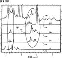
上述の分光技法の具体的な応用の1つは、グルタミン酸(Glu)及びグルタミン(Gln)に関する自動インビボ検出である。上述したように、Gln及びGluからの信号は、典型的には、図3に示すように、互いの信号同士で、またNAAやmIなどの別の分子からの信号と別個に、オーバーラップしている。図3のグラフは、3TスキャナにおいてTEを35としかつTRを2000として、PRESSとして知られる従来の収集スキームを用いて収集したスペクトルを表している。スケールの最上部には典型的なインビボデータ130を表しており、またNAA132、Glu134、Gln136及びmI138に対する個々の化学的応答をその下に表している。2つの関心対象エリア140及び142で示すように、これらの代謝産物の信号同士で激しいスペクトルのオーバーラップが発生し、個々の代謝産物信号の定量を極めて困難としている。臨床MR分光法で通常使用される磁場強度(1.5Tや3.0T)では、従来の情報当てはめ(knowledge fitting)プログラムであっても、組織レベルの決定の際に、Glu+Gln(Glx)の合算に対する当てはめを余儀なくされている。Glu:Glnのシフトに関連する興奮毒性イベントに関する最近の研究によれば、一般にGlxと呼ばれるこれらの成分の和ではなく、GluとGlnとを両方計測すると有利となる。
One specific application of the spectroscopic techniques described above is automated in vivo detection for glutamate (Glu) and glutamine (Gln). As noted above, the signals from Gln and Glu typically overlap each other and separately from signals from other molecules such as NAA and ml, as shown in FIG. ing. The graph of FIG. 3 represents a spectrum collected using a conventional acquisition scheme known as PRESS with a TE of 35 and TR of 2000 in a 3T scanner. At the top of the scale, representative in
上述のスキームを実現させることによって、図4に示すように3Tでのヒトの脳スペクトルにおいてGlu及びGlnの直接計測を提供することができる。図4は、図3と同様の様々な代謝産物スペクトルを表している。同じ信号を特定するためには同じ参照番号を使用している。ただし、2つの関心対象エリア144及び146に示したように、本発明を実施すると、十分な信号の識別が達成される。TEを基準最小値である概ね30msから少なくとも115msまで増分させることによって、TE平均化によりNAA132、Glu134、Gln136及びmI138に対するスペクトル・パターンが単純化される。関心対象エリア144及び146で示すように、146で収集したGlu信号は、Glnの計測値を提供するように、144で収集したGlu信号から容易に差し引くことができる。さらに、特にサンプリング時間がk空間エンコードによって支配されているような従来のMRSIでは、t1寸法においてより大きな段階及び/または非直線的な段階を使用することが可能であることも企図される。
By implementing the above scheme, it is possible to provide direct measurement of Glu and Gln in the human brain spectrum at 3T as shown in FIG. FIG. 4 represents various metabolite spectra similar to FIG. The same reference numbers are used to identify the same signal. However, as shown in the two areas of
このTE平均化技法をPRESSと共に使用することによって、様々な代謝産物(具体的にはGlu、Gln、mI、NAtot、Cho及びCre)の組織レベルに対する3T以上での定量化を改善させるような十分な分解能を提供することができる。しかし、通常の母集団にわたる変動がT2であるとき、絶対定量化のためには個々のT2をTE平均化前のデータから計算することが有利となり得る。 Use this TE averaging technique with PRESS to improve the quantification of various metabolites (specifically Glu, Gln, mI, NA tot , Cho and Cre) above 3T for tissue levels Sufficient resolution can be provided. However, when the variation across the normal population is T2, it may be advantageous to calculate individual T2 from the data prior to TE averaging for absolute quantification.
さらに、2.5msの128段階で、NEXが2、TRが2secとして、35msから335msまでのTEを平均化することによって優れたデータが得られているが、2.5msの64段階で2NEX及び2secTRで35msから195msまでのTEの平均化や、例えば10msの16段階でTEの同じスパンにわたる平均化によっても、実質的に同等のデータが収集されることに留意されたい。 Furthermore, excellent data has been obtained by averaging TE from 35 ms to 335 ms with 128 steps of 2.5 ms, NEX of 2 and TR of 2 sec, but 2NEX and 64 steps of 2.5 ms are obtained. Note that substantially equivalent data is also collected by averaging of TE from 35 ms to 195 ms in 2 sec TR, or averaging over the same span of TE in 16 steps, eg, 10 ms.
したがって、この技法によって、代謝産物の定量的計測に関して最適化スペクトルが提供され、実効TE値を比較的短くしかつt1内の点の数を比較的少なくして、良好な基準線及び十分な分解能を提供することができる。 Therefore, this technique provides an optimized spectrum for quantitative measurement of metabolites, with a relatively short effective TE value and a relatively small number of points in t1, good baseline and sufficient resolution. Can be provided.
さらに、与えられた任意の対象においてT2変動と独立に代謝産物レベルを決定するためには、TE平均化の前にTE=0においてT2緩和及び推定信号を決定していれば、このデータを標準ファントームと協働して使用し、独立した代謝産物レベルを得ることができる。こうしたファントームには、GE Medical Systems(Waukesha,WI)から提供されるGE MRS HDファントーム(part/model no.2152220)が含まれる。 Furthermore, in order to determine metabolite levels independently of T 2 variation in any given subject, this data can be obtained if T 2 relaxation and estimation signals are determined at TE = 0 prior to TE averaging. Can be used in conjunction with a standard phantom to obtain independent metabolite levels. Such phantoms include the GE MRS HD phantom (part / model no. 2152220) provided by GE Medical Systems (Waukesha, Wis.).
さらに、TEデータの各フレームは残留水信号を用いて位相補正することができること、並びにさらに任意の周波数誤差及び位相誤差を補正するように水基準点を含めることができること、が企図される。水基準はさらに、非抑制データに対するTE平均化フレームを含むことができる。 In addition, it is contemplated that each frame of TE data can be phase corrected using the residual water signal, and that water reference points can be included to further correct any frequency and phase errors. The water reference may further include a TE averaging frame for non-suppressed data.
本発明を好ましい実施形態について記載してきたが、明示的に記述した以外に等価、代替及び修正が可能であり、これらも添付の特許請求の範囲の域内にあることを理解されたい。
10 MRIシステム
12 オペレータ・コンソール
13 入力デバイス
14 制御パネル
16 表示スクリーン、ディスプレイ
18 リンク
20 コンピュータ・システム
20a バックプレーン
22 画像プロセッサ・モジュール
24 CPUモジュール
26 メモリ・モジュール
28 ディスク記憶装置
30 テープ駆動装置
32 システム制御部
32a バックプレーン
34 高速シリアル・リンク
36 CPUモジュール
38 パルス発生器モジュール
40 シリアル・リンク
42 傾斜増幅器
44 生理学的収集制御器
46 スキャン室インタフェース回路
48 患者位置決めシステム
50 傾斜磁場コイル・アセンブリ
52 マグネット・アセンブリ
54 偏向用マグネット
56 RFコイル
57 ローダ
58 送受信器モジュール
60 RF増幅器
62 送信/受信スイッチ
64 前置増幅器
66 メモリ・モジュール
68 アレイ・プロセッサ
100 パルスシーケンス
102 フレーム
104 フレーム
106 フレーム
108 励起RFパルス
110 リフォーカシングRFパルスの組
112 リフォーカシングRFパルス
114 リフォーカシングRFパルス
116 エコー
130 インビボデータ
132 NAA
134 Glu
136 Gln
138 mI
140 関心対象エリア
142 関心対象エリア
144 関心対象エリア
146 関心対象エリア
DESCRIPTION OF
134 Glu
136 Gln
138 mI
140 Area of
Claims (10)
複数の異なるエコー時間(TE)を決定する工程と、
前記複数の異なるエコー時間の間にデータを収集する工程と、
前記収集したデータを平均化する工程と、
代謝産物信号の空間分布を検出し、前記平均化したデータから臨床解析のための代謝産物信号を分離する工程と、を含む方法。 MR spectroscopy to reduce signal overlap from metabolites, comprising:
Determining a plurality of different echo times (TE);
Collecting data during the plurality of different echo times;
Averaging the collected data;
Detecting a spatial distribution of metabolite signals and separating metabolite signals for clinical analysis from the averaged data.
初期エコー時間(TE0)を決定する工程と、
データ収集点の数を決定する工程と、
前記データ収集点の数及び前記初期エコー時間(TE0)に基づいて、TE平均化寸法にわたって各データ収集ごとにエコー時間(TE)の長さを変更する工程と、
前記複数の異なるエコー時間にわたって収集したデータを蓄積する工程と
前記蓄積したデータを前記データ収集点の数で割り算する工程と、
を含む、請求項1に記載の方法。 Said step of averaging the collected data comprises:
Determining an initial echo time (TE0);
Determining the number of data collection points;
Changing the length of the echo time (TE) for each data collection over the TE averaging dimension based on the number of data collection points and the initial echo time (TE0);
Accumulating data collected over the plurality of different echo times; dividing the accumulated data by the number of data collection points;
The method of claim 1 comprising:
偏向磁場を印加するようにマグネットのボアの周りに位置決めした複数の傾斜コイルと、パルスモジュールによって制御されRF信号をRFコイル・アセンブリへ送信させてこのRFコイル・アセンブリからRF信号を受信してMR画像を獲得するRF送受信器システム並びにRFスイッチとを有する磁気共鳴画像システムと、
初期T2緩和時間を決定し、エコー時間(TE)=0での代謝産物信号を推定し、標準ファーントム収集データを用いて、対象のT2変動に依存しない代謝産物レベルを決定し、
収集寸法にわたる所望のスパンのエコー時間TEを受け取り、
所望の数の収集点を受け取り、
1つの収集点から他の収集点でのエコー時間TEの変化量を計算し、
前記変化量に基づいて異なるエコー時間(TE)によりMRパルスシーケンスを印加し、
MRデータを収集し、改善した代謝産物信号分離を用いてスペクトル画像を再構成することを特徴とするMR分光法イメージング装置。 An MR spectroscopy imaging device capable of identifying metabolites, comprising:
A plurality of gradient coils positioned around the magnet bore to apply a deflecting magnetic field and an RF signal transmitted to the RF coil assembly controlled by the pulse module to receive the RF signal from the RF coil assembly and MR A magnetic resonance imaging system having an RF transceiver system for acquiring images and an RF switch;
Determining an initial T2 relaxation time, estimating a metabolite signal at echo time (TE) = 0, and using standard fermentum acquisition data to determine a metabolite level independent of the T2 variation of the subject;
Receives the echo time TE of the desired span over the collection dimension;
Receive the desired number of collection points,
Calculate the amount of change in echo time TE from one collection point to another,
Applying an MR pulse sequence with different echo times (TE) based on the variation,
An MR spectroscopy imaging device characterized by collecting MR data and reconstructing a spectral image using improved metabolite signal separation.
Applications Claiming Priority (1)
| Application Number | Priority Date | Filing Date | Title |
|---|---|---|---|
| US10/250,260 US6987997B1 (en) | 2003-06-18 | 2003-06-18 | Method and apparatus for improved metabolite signal separation in MR spectroscopy |
Publications (3)
| Publication Number | Publication Date |
|---|---|
| JP2005007181A JP2005007181A (en) | 2005-01-13 |
| JP2005007181A5 JP2005007181A5 (en) | 2007-08-02 |
| JP4532178B2 true JP4532178B2 (en) | 2010-08-25 |
Family
ID=34078807
Family Applications (1)
| Application Number | Title | Priority Date | Filing Date |
|---|---|---|---|
| JP2004180417A Active JP4532178B2 (en) | 2003-06-18 | 2004-06-18 | Method and apparatus for improved signal separation of metabolites in MR spectroscopy |
Country Status (3)
| Country | Link |
|---|---|
| US (2) | US6987997B1 (en) |
| JP (1) | JP4532178B2 (en) |
| NL (1) | NL1026428C2 (en) |
Families Citing this family (10)
| Publication number | Priority date | Publication date | Assignee | Title |
|---|---|---|---|---|
| US7253619B2 (en) * | 2003-04-04 | 2007-08-07 | Siemens Aktiengesellschaft | Method for evaluating magnetic resonance spectroscopy data using a baseline model |
| US6987997B1 (en) * | 2003-06-18 | 2006-01-17 | General Electric Company | Method and apparatus for improved metabolite signal separation in MR spectroscopy |
| US7064544B1 (en) * | 2004-05-18 | 2006-06-20 | General Electric Company | Method and system of scaling MR spectroscopic data acquired with phased-array coils |
| US7626477B2 (en) * | 2005-11-28 | 2009-12-01 | General Electric Company | Cold mass cryogenic cooling circuit inlet path avoidance of direct conductive thermal engagement with substantially conductive coupler for superconducting magnet |
| US8825131B2 (en) | 2009-10-14 | 2014-09-02 | Nocimed, Llc | MR spectroscopy system and method for diagnosing painful and non-painful intervertebral discs |
| US8761860B2 (en) | 2009-10-14 | 2014-06-24 | Nocimed, Llc | MR spectroscopy system and method for diagnosing painful and non-painful intervertebral discs |
| US9280718B2 (en) | 2010-11-24 | 2016-03-08 | Nocimed, Llc | Systems and methods for automated voxelation of regions of interest for magnetic resonance spectroscopy |
| US8965094B2 (en) | 2012-04-14 | 2015-02-24 | Nocimed, Llc | Magnetic resonance spectroscopy pulse sequence, acquisition, and processing system and method |
| JP6109601B2 (en) * | 2013-02-27 | 2017-04-05 | 東芝メディカルシステムズ株式会社 | Magnetic resonance imaging system |
| AU2017282665B2 (en) | 2016-06-19 | 2022-05-19 | Aclarion, Inc. | Magnetic resonance spectroscopy system and method for diagnosing pain or infection associated with propionic acid |
Citations (7)
| Publication number | Priority date | Publication date | Assignee | Title |
|---|---|---|---|---|
| JPH0213430A (en) * | 1988-04-15 | 1990-01-17 | General Electric Co <Ge> | System of generating nmr signal of localized spectrum by metabolic substance containing coupling piston |
| JPH05123312A (en) * | 1991-11-05 | 1993-05-21 | Toshiba Corp | Magnetic resonance imaging device |
| JPH08252238A (en) * | 1995-03-15 | 1996-10-01 | Toshiba Corp | Magnetic resonance diagnostic system |
| US5570019A (en) * | 1993-08-13 | 1996-10-29 | The United States Of America As Represented By The Department Of Health And Human Services | Method for magnetic resonance spectroscopic imaging with multiple spin-echoes |
| JP2001112735A (en) * | 1999-10-19 | 2001-04-24 | Hitachi Medical Corp | Magnetic resonance imaging apparatus |
| US6529763B1 (en) * | 2000-09-14 | 2003-03-04 | Ramot University Authority For Applied Research & Industrial Development Ltd. | Imaging of neuronal material |
| JP2004148024A (en) * | 2002-11-01 | 2004-05-27 | Ge Medical Systems Global Technology Co Llc | Quantification method for n-acetyl asparate, glutamine, and gultamate and magnetic resonance imaging apparatus |
Family Cites Families (7)
| Publication number | Priority date | Publication date | Assignee | Title |
|---|---|---|---|---|
| DE3920433A1 (en) * | 1989-06-22 | 1991-01-03 | Philips Patentverwaltung | NUCLEAR RESONANCE METHOD |
| US5270654A (en) * | 1991-07-05 | 1993-12-14 | Feinberg David A | Ultra-fast multi-section MRI using gradient and spin echo (grase) imaging |
| US5709208A (en) * | 1994-04-08 | 1998-01-20 | The United States Of America As Represented By The Department Of Health And Human Services | Method and system for multidimensional localization and for rapid magnetic resonance spectroscopic imaging |
| US5657758A (en) * | 1994-04-08 | 1997-08-19 | The United States Of America As Represented By The Secretary, Department Of Health And Human Services | Method and system for multidimensional localization and for rapid magnetic resonance spectroscopic imaging |
| US6069478A (en) | 1997-11-24 | 2000-05-30 | General Electric Corporation | Magnetic resonance spectroscopic imaging having reduced parasitic side band signals |
| US6104191A (en) | 1998-03-17 | 2000-08-15 | General Electric Company | Quantitative in vivo spectroscopy using oversampling, waterline referencing, and prior knowledge fitting |
| US6987997B1 (en) * | 2003-06-18 | 2006-01-17 | General Electric Company | Method and apparatus for improved metabolite signal separation in MR spectroscopy |
-
2003
- 2003-06-18 US US10/250,260 patent/US6987997B1/en not_active Expired - Fee Related
-
2004
- 2004-06-16 NL NL1026428A patent/NL1026428C2/en not_active IP Right Cessation
- 2004-06-18 JP JP2004180417A patent/JP4532178B2/en active Active
-
2005
- 2005-04-19 US US10/907,885 patent/US7184813B1/en not_active Expired - Lifetime
Patent Citations (7)
| Publication number | Priority date | Publication date | Assignee | Title |
|---|---|---|---|---|
| JPH0213430A (en) * | 1988-04-15 | 1990-01-17 | General Electric Co <Ge> | System of generating nmr signal of localized spectrum by metabolic substance containing coupling piston |
| JPH05123312A (en) * | 1991-11-05 | 1993-05-21 | Toshiba Corp | Magnetic resonance imaging device |
| US5570019A (en) * | 1993-08-13 | 1996-10-29 | The United States Of America As Represented By The Department Of Health And Human Services | Method for magnetic resonance spectroscopic imaging with multiple spin-echoes |
| JPH08252238A (en) * | 1995-03-15 | 1996-10-01 | Toshiba Corp | Magnetic resonance diagnostic system |
| JP2001112735A (en) * | 1999-10-19 | 2001-04-24 | Hitachi Medical Corp | Magnetic resonance imaging apparatus |
| US6529763B1 (en) * | 2000-09-14 | 2003-03-04 | Ramot University Authority For Applied Research & Industrial Development Ltd. | Imaging of neuronal material |
| JP2004148024A (en) * | 2002-11-01 | 2004-05-27 | Ge Medical Systems Global Technology Co Llc | Quantification method for n-acetyl asparate, glutamine, and gultamate and magnetic resonance imaging apparatus |
Also Published As
| Publication number | Publication date |
|---|---|
| US7184813B1 (en) | 2007-02-27 |
| JP2005007181A (en) | 2005-01-13 |
| US6987997B1 (en) | 2006-01-17 |
| NL1026428A1 (en) | 2004-12-21 |
| NL1026428C2 (en) | 2006-06-16 |
Similar Documents
| Publication | Publication Date | Title |
|---|---|---|
| US7184813B1 (en) | Method and apparatus for improved metabolite signal separation in MR spectroscopy | |
| US8498688B2 (en) | Magnetic resonance device and method | |
| US9116218B2 (en) | System and method for tissue specific MR imaging of metabolites using spectral-spatially formed stimulated echo | |
| US9320452B2 (en) | Magnetic resonance imaging of amyloid plaque in the brain | |
| JP5196408B2 (en) | Magnetic resonance spectroscopy of species with multiple peaks. | |
| JP2008543483A (en) | Simultaneous multinuclear magnetic resonance imaging | |
| US7952354B2 (en) | System and method for fast MR imaging of metabolites at selective excitation frequencies | |
| US10718841B2 (en) | System and method for improved homogeneous and inhomogeneous magnetization transfer magnetic resonance imaging | |
| JP2009532163A (en) | Magnetic resonance apparatus and method | |
| JP5536358B2 (en) | Magnetic resonance imaging apparatus and sensitivity correction method | |
| US6157192A (en) | Recovery of signal void arising from field inhomogeneities in echo planar imaging | |
| US6891371B1 (en) | Method and system of generating an MRS spectrum from multiple receiver data | |
| US20220065962A1 (en) | Methods for producing magnetic resonance images with sub-millisecond temporal resolution | |
| DE19653212A1 (en) | Magnetic resonance fluoroscopy technique and apparatus | |
| US20090060841A1 (en) | Apparatus and method for combined use of variable flip angles and centric phase encoding in hyperpolarized 13c imaging | |
| US8928317B2 (en) | System and method for controlling apparent timing dependencies for T2-weighted MRI imaging | |
| JP3153573B2 (en) | Magnetic resonance equipment | |
| US7064544B1 (en) | Method and system of scaling MR spectroscopic data acquired with phased-array coils | |
| JP2005161102A (en) | Magnetic resonance diagnostic apparatus | |
| EP2699921A1 (en) | Determining positions of a magnetic field probe in a magnetic resonance measurement | |
| JP4841849B2 (en) | Oxygen component determination system |
Legal Events
| Date | Code | Title | Description |
|---|---|---|---|
| A521 | Request for written amendment filed |
Free format text: JAPANESE INTERMEDIATE CODE: A523 Effective date: 20070611 |
|
| A621 | Written request for application examination |
Free format text: JAPANESE INTERMEDIATE CODE: A621 Effective date: 20070611 |
|
| A977 | Report on retrieval |
Free format text: JAPANESE INTERMEDIATE CODE: A971007 Effective date: 20091119 |
|
| A131 | Notification of reasons for refusal |
Free format text: JAPANESE INTERMEDIATE CODE: A131 Effective date: 20091201 |
|
| A601 | Written request for extension of time |
Free format text: JAPANESE INTERMEDIATE CODE: A601 Effective date: 20100301 |
|
| A602 | Written permission of extension of time |
Free format text: JAPANESE INTERMEDIATE CODE: A602 Effective date: 20100304 |
|
| A521 | Request for written amendment filed |
Free format text: JAPANESE INTERMEDIATE CODE: A523 Effective date: 20100316 |
|
| RD02 | Notification of acceptance of power of attorney |
Free format text: JAPANESE INTERMEDIATE CODE: A7422 Effective date: 20100316 |
|
| RD04 | Notification of resignation of power of attorney |
Free format text: JAPANESE INTERMEDIATE CODE: A7424 Effective date: 20100316 |
|
| TRDD | Decision of grant or rejection written | ||
| A01 | Written decision to grant a patent or to grant a registration (utility model) |
Free format text: JAPANESE INTERMEDIATE CODE: A01 Effective date: 20100511 |
|
| A01 | Written decision to grant a patent or to grant a registration (utility model) |
Free format text: JAPANESE INTERMEDIATE CODE: A01 |
|
| A61 | First payment of annual fees (during grant procedure) |
Free format text: JAPANESE INTERMEDIATE CODE: A61 Effective date: 20100610 |
|
| R150 | Certificate of patent or registration of utility model |
Ref document number: 4532178 Country of ref document: JP Free format text: JAPANESE INTERMEDIATE CODE: R150 Free format text: JAPANESE INTERMEDIATE CODE: R150 |
|
| FPAY | Renewal fee payment (event date is renewal date of database) |
Free format text: PAYMENT UNTIL: 20130618 Year of fee payment: 3 |
|
| R250 | Receipt of annual fees |
Free format text: JAPANESE INTERMEDIATE CODE: R250 |
|
| R250 | Receipt of annual fees |
Free format text: JAPANESE INTERMEDIATE CODE: R250 |
|
| R250 | Receipt of annual fees |
Free format text: JAPANESE INTERMEDIATE CODE: R250 |
|
| R250 | Receipt of annual fees |
Free format text: JAPANESE INTERMEDIATE CODE: R250 |
|
| R250 | Receipt of annual fees |
Free format text: JAPANESE INTERMEDIATE CODE: R250 |
|
| R250 | Receipt of annual fees |
Free format text: JAPANESE INTERMEDIATE CODE: R250 |
|
| R250 | Receipt of annual fees |
Free format text: JAPANESE INTERMEDIATE CODE: R250 |
|
| R250 | Receipt of annual fees |
Free format text: JAPANESE INTERMEDIATE CODE: R250 |
|
| R250 | Receipt of annual fees |
Free format text: JAPANESE INTERMEDIATE CODE: R250 |
|
| R250 | Receipt of annual fees |
Free format text: JAPANESE INTERMEDIATE CODE: R250 |
|
| R250 | Receipt of annual fees |
Free format text: JAPANESE INTERMEDIATE CODE: R250 |