JP4532073B2 - Arc welding system - Google Patents
Arc welding system Download PDFInfo
- Publication number
- JP4532073B2 JP4532073B2 JP2002581138A JP2002581138A JP4532073B2 JP 4532073 B2 JP4532073 B2 JP 4532073B2 JP 2002581138 A JP2002581138 A JP 2002581138A JP 2002581138 A JP2002581138 A JP 2002581138A JP 4532073 B2 JP4532073 B2 JP 4532073B2
- Authority
- JP
- Japan
- Prior art keywords
- current
- power supply
- power source
- arc welding
- controller
- Prior art date
- Legal status (The legal status is an assumption and is not a legal conclusion. Google has not performed a legal analysis and makes no representation as to the accuracy of the status listed.)
- Expired - Lifetime
Links
Images


Classifications
-
- B—PERFORMING OPERATIONS; TRANSPORTING
- B23—MACHINE TOOLS; METAL-WORKING NOT OTHERWISE PROVIDED FOR
- B23K—SOLDERING OR UNSOLDERING; WELDING; CLADDING OR PLATING BY SOLDERING OR WELDING; CUTTING BY APPLYING HEAT LOCALLY, e.g. FLAME CUTTING; WORKING BY LASER BEAM
- B23K9/00—Arc welding or cutting
- B23K9/10—Other electric circuits therefor; Protective circuits; Remote controls
- B23K9/1006—Power supply
- B23K9/1043—Power supply characterised by the electric circuit
- B23K9/1056—Power supply characterised by the electric circuit by using digital means
- B23K9/1062—Power supply characterised by the electric circuit by using digital means with computing means
-
- B—PERFORMING OPERATIONS; TRANSPORTING
- B23—MACHINE TOOLS; METAL-WORKING NOT OTHERWISE PROVIDED FOR
- B23K—SOLDERING OR UNSOLDERING; WELDING; CLADDING OR PLATING BY SOLDERING OR WELDING; CUTTING BY APPLYING HEAT LOCALLY, e.g. FLAME CUTTING; WORKING BY LASER BEAM
- B23K9/00—Arc welding or cutting
- B23K9/095—Monitoring or automatic control of welding parameters
- B23K9/0953—Monitoring or automatic control of welding parameters using computing means
-
- B—PERFORMING OPERATIONS; TRANSPORTING
- B23—MACHINE TOOLS; METAL-WORKING NOT OTHERWISE PROVIDED FOR
- B23K—SOLDERING OR UNSOLDERING; WELDING; CLADDING OR PLATING BY SOLDERING OR WELDING; CUTTING BY APPLYING HEAT LOCALLY, e.g. FLAME CUTTING; WORKING BY LASER BEAM
- B23K9/00—Arc welding or cutting
- B23K9/095—Monitoring or automatic control of welding parameters
- B23K9/0956—Monitoring or automatic control of welding parameters using sensing means, e.g. optical
-
- B—PERFORMING OPERATIONS; TRANSPORTING
- B23—MACHINE TOOLS; METAL-WORKING NOT OTHERWISE PROVIDED FOR
- B23K—SOLDERING OR UNSOLDERING; WELDING; CLADDING OR PLATING BY SOLDERING OR WELDING; CUTTING BY APPLYING HEAT LOCALLY, e.g. FLAME CUTTING; WORKING BY LASER BEAM
- B23K9/00—Arc welding or cutting
- B23K9/10—Other electric circuits therefor; Protective circuits; Remote controls
- B23K9/1006—Power supply
- B23K9/1075—Parallel power supply, i.e. multiple power supplies or multiple inverters supplying a single arc or welding current
Landscapes
- Engineering & Computer Science (AREA)
- Physics & Mathematics (AREA)
- Plasma & Fusion (AREA)
- Mechanical Engineering (AREA)
- Theoretical Computer Science (AREA)
- Arc Welding Control (AREA)
- Generation Of Surge Voltage And Current (AREA)
- Arc Welding In General (AREA)
- Arc-Extinguishing Devices That Are Switches (AREA)
- Discharge Heating (AREA)
Abstract
Description
本発明はアーク溶接技術に関し、より詳しくは電源を結合してタンデム電極を作動させるアーク溶接システムに関する。 The present invention relates to arc welding technology, and more particularly to an arc welding system that operates a tandem electrode by coupling a power source.
本発明は大型金属ブランクのシーム溶接に使用するタイプの二つまたはそれ以上のタンデム電極を駆動するための大容量交流電源を使用するアーク溶接システムに向けられている。本発明は出力極性を変えるためのスイッチを備えたいずれの標準AC電源とも併用することができるが、この電源はスタバ特許6,111,216号に開示された切換えコンセプトを使用しており、その電源はスイッチが極性を反転させる前にアーク電流が小さくなる二つの大きい出力極性スイッチを有するインバータである。結局、用語「切換点」は複雑なプロシージャであり、これによって電源は100アンペアのような予め選択された値未満の電流の待機を最初にオフする。100アンペア閾値に達したときに、電源の出力スイッチが反転してインバータのDC出力リンクからの極性を反転する。従って、「切換点」は、出力極性を反転させる切換命令によって追従された電源インバータへのオフ出力命令、すなわち、「キル」命令として知られる。キル出力は低減電流レベルに対するドロップとなる。このプロシージャは各連続する極性反転において2倍になり、従ってAC電源が低電流においてのみ極性を反転する。この方式において、出力極性制御スイッチのための緩衝回路のサイズが小さくなり、あるいは省略される。この切換コンセプトが本発明で使用されるように切換点を規定するようにするのが好ましいので、以下の特許文献1(スタバ特許6,111,216号)は参照例として一体化する。タンデム電極のためのAC電流のコンセプトは当該技術において周知である。1999年6月12日出願の先行出願番号第09/336,804号は、タンデム電極が各々分離したインバータータイプの電源によって電力供給を受けているシステムを開示している。周波数は近接するタンデム電極内の交流間のインターフェアレンスを低減するように変えられる。実際に、本願はAC電極によって追従されたDC電極かあるいは二つまたはそれ以上のAC駆動電極を駆動するための単一電源に関する。各例において、分離インバータタイプの電源は各電極に適しており、また交流高容量電源において、スタバ特許6,111,216号の切換点コンセプトが使用される。分離高容量電源によるタンデム電極の各々を別々に駆動するためのこのシステムは、本発明への背景情報であり、かつ、この種の背景としてここに一体化する。同様にして、1999年9月27日出願の米国特許願第09/406,406号は、さらなるアーク溶接システムを開示しており、そのタンデム溶接操作中の各電極が単一の電極アークと並列接続された二つまたはそれ以上の独立電源によって駆動される。このシステムはスタバ特許6,111,216号に基づいて操作される極性反転スイッチネットワークへの入力を形成する二つまたはそれ以上の正確に平衡された電源を有する単一セットのスイッチを含んでいる。電源の各々は単一命令信号によって駆動され、従って極性反転スイッチを介して合成され方向付けられた同一電流値を共有する。このタイプのシステムは大きい極性反転スイッチを必要とし、電極への全電流が単一の一連のスイッチを通過するからである。本願は単一電極のための電源のマスター/スレーブ組み合わせを示し、かつ、本発明が向けられている一般背景情報を開示している。この理由で、この適用例も参照例として一体化される。 The present invention is directed to an arc welding system that uses a high capacity AC power source to drive two or more tandem electrodes of the type used for seam welding of large metal blanks. The present invention can be used with any standard AC power supply with a switch to change the output polarity, but this power supply uses the switching concept disclosed in Starbah Patent 6,111,216, which The power supply is an inverter with two large output polarity switches where the arc current is reduced before the switch reverses polarity. Eventually, the term “switching point” is a complex procedure whereby the power supply first turns off waiting for a current below a preselected value, such as 100 amps. When the 100 amp threshold is reached, the output switch of the power supply is inverted to invert the polarity from the DC output link of the inverter. Thus, the “switch point” is known as an off output command to the power inverter followed by a switch command that reverses the output polarity, or “kill” command. The kill output is a drop for the reduced current level. This procedure is doubled at each successive polarity reversal, so the AC power source reverses polarity only at low currents. In this system, the size of the buffer circuit for the output polarity control switch is reduced or omitted. Since it is preferable to define the switching point so that this switching concept is used in the present invention, the following Patent Document 1 (Starbah Patent No. 6,111,216) is integrated as a reference example. The AC current concept for tandem electrodes is well known in the art. Prior application No. 09 / 336,804, filed June 12, 1999, discloses a system in which the tandem electrodes are each powered by a separate inverter type power source. The frequency can be varied to reduce interference between alternating currents in adjacent tandem electrodes. Indeed, this application relates to a single power source for driving a DC electrode or two or more AC drive electrodes followed by an AC electrode. In each example, a separate inverter type power supply is suitable for each electrode, and the switching point concept of Starbah Patent 6,111,216 is used in an AC high capacity power supply. This system for separately driving each of the tandem electrodes by a separate high capacity power source is background information to the present invention and is integrated here as this type of background. Similarly, US patent application Ser. No. 09 / 406,406, filed Sep. 27, 1999, discloses a further arc welding system in which each electrode during its tandem welding operation is in parallel with a single electrode arc. It is driven by two or more connected independent power supplies. The system includes a single set of switches with two or more precisely balanced power supplies that form the input to a polarity reversing switch network operated according to Starbah Patent 6,111,216. . Each of the power supplies is driven by a single command signal and thus shares the same current value synthesized and directed through the polarity reversal switch. This type of system requires a large polarity reversing switch because the entire current to the electrodes passes through a single series of switches. This application shows a master / slave combination of power supplies for a single electrode and discloses general background information to which the present invention is directed. For this reason, this application example is also integrated as a reference example.
パイプ溶接のような溶接アプリケーションは、大きい電流をしばしば必要とし、かつ、タンデム電極によって生成された、いくつかのアークを使用する。このような溶接システムは、二つの近接するタンデム電極間の磁気相互作用によるアーク妨害によってもたらされたある不調和となる傾向が強い。近接するAC駆動タンデム電極によってもたらされる欠点を修正するためのシステムは本発明の譲渡人による1999年6月21日出願の先行出願第09/336,804号に開示されている。この先行出願において、AC駆動電極の各々はそれ自体に属するインバータ基準電源を有している。各電源の出力周波数は、近接電極間の磁気妨害を阻止するように変化する。このシステムは各電極のための別体電源を必要とする。任意の電極用に必要とされる電流がインバータ基準電源の電流定格を超えるので、新しい電源を設計し、工作し、製造しなければならない。従って、タンデム溶接電極を作動するためのこの種のシステムはパイプ溶接に要する高電流を得るために高容量ないし高定格電源を必要とする。タンデム作動電極のための特定高電流定格電源の必要性を少なくするために、譲渡人は出願第09/406,406号に開示したシステムを開発した。その各AC電極は並列接続された二つまたはそれ以上のインバータ電源によって駆動される。これらの並列電源は極性切換ネットワークの入力側で合成される出力電流を有している。従って、より大きい電流が任意の電極に必要とされれば、二つまたはそれ以上の電源が使用される。このシステムにおいて、各電源は合同で作動され、出力電流を平等に共有する。従って、溶接条件の変化によって必要とされる電流は単一ユニットの超過電流定格にだけ提供される。電流平衡システムはいくつかの小さい電源の組み合わせが許容されたが、電源は極性反転切換ネットワークの入力側に並列接続しなければならなかった。このように大型スイッチが各電極に必要とされた。結局、この種のシステムはパイプ溶接に使用されるタイプのタンデム溶接操作における各電極のために必要とする特定電源の欠点を克服するが、スイッチを極めて大きくする必要があり、さらに入力平衡電源を単一電流命令信号から駆動することによって正確に整合させなければならない欠点がなおもある。この先行出願は各タンデム電極への各溶接セル直流のための同期信号のコンセプトを利用している。しかし、このシステムはなおも大型スイッチを必要とする。このタイプのシステムは溶接セルと相互接続されるイーサネット(登録商標)ネットワークで操作するのに利用された。イーサネット(登録商標)相互接続において、タイミングが正確に制御できない。開示されたシステムにおいて、任意の電極のための切換タイミングは時間基準でシフトされることのみを必要とし、特定時間を正確に認識する必要はない。従って、電流を平衡させ単一スイッチネットワークを必要とする開示されたシステムは、イーサネット(登録商標)ネットワークまたはインターネットおよびイーサネット(登録商標)制御システムを使用したときに、タンデムアーク溶接操作に使用するための高容量電流を得る方法を有している。インターネットリンクの有無に係らずイーサネット(登録商標)ネットワークによって溶接装置を制御する要望がある。タイミングの制限のために、一般的な同期化技術のみを使用するタイプのタンデム電極システムの使用がやむなくされている。 Welding applications such as pipe welding often require large currents and use several arcs generated by tandem electrodes. Such welding systems are more prone to certain discrepancies caused by arc interruption due to magnetic interaction between two adjacent tandem electrodes. A system for correcting the disadvantages caused by adjacent AC driven tandem electrodes is disclosed in prior application 09 / 336,804 filed June 21, 1999 by the assignee of the present invention. In this prior application, each of the AC drive electrodes has an inverter reference power supply belonging to it. The output frequency of each power supply varies to prevent magnetic interference between adjacent electrodes. This system requires a separate power source for each electrode. Since the current required for any electrode exceeds the current rating of the inverter reference power supply, a new power supply must be designed, constructed and manufactured. Therefore, this type of system for operating tandem welding electrodes requires a high capacity or high rated power source to obtain the high current required for pipe welding. In order to reduce the need for a specific high current rated power source for the tandem working electrode, the assignee has developed the system disclosed in application 09 / 406,406. Each AC electrode is driven by two or more inverter power supplies connected in parallel. These parallel power supplies have an output current synthesized at the input side of the polarity switching network. Thus, if a larger current is needed for any electrode, two or more power supplies are used. In this system, the power supplies are operated jointly and share the output current equally. Thus, the current required by changing welding conditions is provided only for the single unit overcurrent rating. The current balancing system allowed several small power supply combinations, but the power supply had to be connected in parallel to the input side of the polarity reversal switching network. Thus, a large switch was required for each electrode. Eventually, this type of system overcomes the disadvantages of the specific power supply required for each electrode in the type of tandem welding operation used for pipe welding, but requires a very large switch and further reduces the input balanced power supply. There are still disadvantages that must be accurately matched by driving from a single current command signal. This prior application utilizes the concept of a synchronization signal for each welding cell DC to each tandem electrode. However, this system still requires a large switch. This type of system was used to operate over an Ethernet network interconnected with a welding cell. Timing is not accurately controlled in Ethernet interconnects. In the disclosed system, the switching timing for any electrode need only be shifted on a time basis and does not need to accurately recognize a particular time. Thus, the disclosed system that balances current and requires a single switch network is for use in tandem arc welding operations when using an Ethernet network or the Internet and Ethernet control systems. A method for obtaining a high capacity current. There is a need to control the welding apparatus via an Ethernet network with or without an internet link. Due to timing limitations, the use of tandem electrode systems of the type that use only common synchronization techniques is unavoidable.
ネットワーク制御に適用させつついくつかの並列インバータタイプの電源で一つの電極を駆動するアーク溶接のための高電流システムに利点がある。この種のシステムには正確に平衡させる必要があり、かつ、単一の高容量出力切換ネットワークを必要とする欠点がある。この種のシステムはネットワークによって制御することができるが、各並列電源に対するパラメータを変えることができない。各々のセルが同期化信号によって互いにオフセットされるだけである。この種のシステムは、セル間にオフセットを単に提供する精巧なネットワークが有利ではなかったので、インターネットおよび(または)LAN制御による中央制御に適していなかった。 There is an advantage in a high current system for arc welding in which one electrode is driven by several parallel inverter type power supplies with application to network control. This type of system has the disadvantages that it needs to be accurately balanced and requires a single high capacity output switching network. This type of system can be controlled by the network, but the parameters for each parallel power supply cannot be changed. Each cell is only offset from each other by the synchronization signal. This type of system was not suitable for central control by the Internet and / or LAN control, as an elaborate network that simply provided an offset between cells was not advantageous.
本発明は各電極のための単一ACアーク溶接セルのコンセプトを使用し、そのセル自体が一つまたはそれ以上の並列電源を含み、各々それ自体の切換ネットワークを有している。従って、切換ネットワークの出力が合成されて電極を駆動する。これによってシステム内で並列接続されたそれぞれの電源の極性反転のための比較的小さいスイッチの使用が可能になる。これに加えて、比較的小さい電源が並列接続され、タンデム溶接操作に使用される数個の電極の各々に対して大きい電流を構築できる。単一の電極を駆動するための極性切換ネットワークの後に並列接続された、いくつかの独立制御電源を使用すると、インターネットまたはイーサネット(登録商標)のようなネットワークの有利な使用を可能にする。 The present invention uses the concept of a single AC arc welding cell for each electrode, the cell itself including one or more parallel power supplies, each with its own switching network. Therefore, the outputs of the switching network are combined to drive the electrodes. This allows the use of relatively small switches for polarity reversal of the respective power supplies connected in parallel in the system. In addition, relatively small power supplies can be connected in parallel to build a large current for each of the several electrodes used in the tandem welding operation. The use of several independent control power supplies connected in parallel after a polarity switching network to drive a single electrode allows for the advantageous use of networks such as the Internet or Ethernet.
本発明によれば、各システムのより小さい電源が電力を単一電極に並列接続される。各並列電源の切換点を高精度インターフェースに共同させることにより、極性の切換前に合成することなしにAC出力電流が並列電源からの電流の和となる。このコンセプトを使用することにより、インターネットリンクの有無にかかわらず、イーサネット(登録商標)ネットワークが溶接システムの各並列電源の溶接パラメータを制御することができる。切換点のタイミングが新しいインターフェースによって正確に制御され、一方で各電源のためのコントローラに向けられた溶接パラメータが、正確な時間基準のないイーサネット(登録商標)ネットワークによって提供することができる。従って、インターネットリンクは単一電極を駆動するための溶接システムのそれぞれの電源コントローラに対してパラメータを指示するのに使用することができる。各電源のためにコード化されたこれらの溶接パラメータの時間基準精度は必要としない。好ましい実施例において、切換点は100アンペアのような最小閾値未満の電流降下の検出を待機する「キル」命令である。各電源が切換命令を有したときに、切り換えられる。瞬時あるいは待機遅延を伴う「キル」命令を包含するシーケンスのいずれかで、並列電源間の切換点が10μs未満、好ましくは1〜5μsの範囲での精度を有するインターフェースカードによって正確に調整される。このタイミング精度が並列電源の切換操作を調整し、一致させてAC出力電流を調整する。 In accordance with the present invention, a smaller power supply for each system is connected in parallel to a single electrode for power. By allowing the switching points of each parallel power supply to collaborate with the high-precision interface, the AC output current is the sum of the currents from the parallel power supply without being combined prior to polarity switching. By using this concept, an Ethernet network can control the welding parameters of each parallel power supply of the welding system with or without an Internet link. Switching point timing is accurately controlled by a new interface, while welding parameters directed to the controller for each power supply can be provided by an Ethernet network without an accurate time reference. Thus, the internet link can be used to indicate parameters to the respective power supply controller of the welding system for driving a single electrode. The time base accuracy of these welding parameters coded for each power supply is not required. In the preferred embodiment, the switching point is a “kill” command that waits for detection of a current drop below a minimum threshold, such as 100 amps. It is switched when each power supply has a switching command. In either a sequence involving a “kill” instruction with an instantaneous or standby delay, the switching point between parallel power supplies is precisely adjusted by an interface card with an accuracy in the range of less than 10 μs, preferably in the range of 1-5 μs. This timing accuracy adjusts the switching operation of the parallel power supply and adjusts the AC output current to match.
インターネットまたはイーサネット(登録商標)LANを使用することにより、各電源のための一連の溶接パラメータが少ない精度の情報ネットワーク上で利用可能であり、ネットワークへの並列電源のためのコントローラが高精度デジタルインターフェースカードで相互接続される。従って、システムのそれぞれの並列電源の切り換えが調整される。これは溶接システムのインターネットおよびLANネットワークの使用が許容される利点がある。情報ネットワークは選択された位相関係でタンデム溶接操作中にいくつかの電極に接続された、いくつかのアーク溶接システムを初期化するための同期化信号を含んでいる。電極の溶接システムの各々は正確に制御されたぞれぞれの切換点を有する一方で、システムは異なる電極間の磁気妨害を阻止するようにシフトないし遅延される。これが共通情報ネットワークを使用するいくつかのAC電極の駆動を許容する。本発明は特に並列電源に有効であってAC電流で任意の電極に電力を供給する。切換点は正確なインターフェースによって調整され、また各並列電源のための溶接パラメータが汎用情報ネットワークによって提供される。このネットワークは本発明に使用される相互接続切換点を必要としないDC電極も作動することができる。 By using the Internet or Ethernet LAN, a series of welding parameters for each power supply is available on a low-accuracy information network, and the controller for parallel power supply to the network has a high-precision digital interface Interconnected with cards. Therefore, the switching of each parallel power supply of the system is adjusted. This has the advantage that the use of the welding system Internet and LAN networks is allowed. The information network includes synchronization signals for initializing several arc welding systems connected to several electrodes during a tandem welding operation with a selected phase relationship. Each of the electrode welding systems has a precisely controlled respective switching point, while the system is shifted or delayed to prevent magnetic interference between different electrodes. This allows driving several AC electrodes using a common information network. The present invention is particularly effective for a parallel power supply and supplies power to an arbitrary electrode with an AC current. The switching points are adjusted by a precise interface and the welding parameters for each parallel power supply are provided by a general information network. This network can also operate DC electrodes that do not require the interconnection switching points used in the present invention.
本発明によれば、電極と工作物間にAC溶接アークを生成するためのアーク溶接システムが設けられている。次に説明するように、このシステムは単一のインバータによって一つの電極を駆動することができる。システムの特徴として、二つまたはそれ以上の電源が単一電極を駆動できる。従って、システムは第1電源のための第1コントローラからなり、第1電源をして切換信号の発生によって電極と工作物間にAC電流を生成せしめる。この信号は第1コントローラによって受信された任意の同期化信号に関する一般的時間関係に極性反転切換点を有している。この第1コントローラはこの第1コントローラに向けられた一連の第1電源特定パラメータ信号に応答する第1溶接パラメータで作動される。少なくとも一つのスレーブコントローラがスレーブ電源を作動するために設けられ、切換点におけるAC電流の極性を反転させることによって同じ電極と工作物間にAC電流を生成する。スレーブコントローラはこのスレーブコントローラに対する第2の一連の電源特定パラメータ信号に応答する第2溶接パラメータで作動する。第1コントローラと第2またはスレーブコントローラに接続された情報ネットワークは二つのコントローラとシステム特定同期化信号のためのデジタル第1および第2電源特定パラメータ信号を含んでいる。従って、コントローラはパラメータ信号と情報ネットワークからの同期化信号を受信する。このネットワークはインターネットリンクの有無に係らずイーサネット(登録商標)ネットワークか、あるいは単なるLANである。本発明は第1コントローラとスレーブコントローラを接続し、第1ないしマスターコントローラからの切換信号によって第2ないしスレーブ電源の切換点を制御するデジタルインターフェースを含んでいる。実際に、第1コントローラは切換点で電流反転を開始する。この事象は高精度でスレーブコントローラに伝達され、その電流反転工程を開始する。各コントローラが任意の数よりも少ないアーク電流を感知したときに、「準備完了信号」が生成される。全ての並列電源からの信号が「準備完了」後、全ての電源が極性を反転する。これは25μs毎にストロボないしルック命令の受信のときに発生する。従って、切換は一致して、かつ、25μs未満の遅延がある。その結果、コントローラは両方とも単一電極へのAC電流の切換点を制御する相互結合データを有している。同じコントローラが、実際にはインターネットおよびイーサネット(登録商標)またはローカルエリアイーサネット(登録商標)ネットワークの組み合わせからなる情報ネットワークからパラメータ情報および同期化信号を受信する。本発明によれば、デジタルインターフェースのタイミング精度は約10μs未満、好ましくは概略範囲が1〜5μsである。従って、単一電極を駆動する二つのコントローラのための切換点が5μs未満で命令される。従って、切換は実際に25μs内で発生する。これと同時に、比較的短い時間感知情報がAC電流を駆動する二つのコントローラをタンデム溶接操作中の単一電極にも接続する情報ネットワークから受信する。25μsの最大遅延は変えることができるが、切換命令精度未満である。 In accordance with the present invention, an arc welding system is provided for generating an AC welding arc between an electrode and a workpiece. As will be explained next, this system can drive one electrode by a single inverter. As a system feature, two or more power supplies can drive a single electrode. Thus, the system comprises a first controller for a first power supply, which causes the first power supply to generate an AC current between the electrode and the workpiece by generating a switching signal. This signal has a polarity reversal switch point in the general time relationship for any synchronization signal received by the first controller. The first controller is operated with a first welding parameter responsive to a series of first power supply specific parameter signals directed to the first controller. At least one slave controller is provided for operating the slave power supply and generates an AC current between the same electrode and workpiece by reversing the polarity of the AC current at the switching point. The slave controller operates with a second welding parameter responsive to a second series of power supply specific parameter signals for the slave controller. The information network connected to the first controller and the second or slave controller includes two controllers and digital first and second power supply specific parameter signals for system specific synchronization signals. Thus, the controller receives the parameter signal and the synchronization signal from the information network. This network is an Ethernet network with or without an Internet link, or simply a LAN. The present invention includes a digital interface for connecting the first controller and the slave controller and controlling the switching point of the second or slave power supply by a switching signal from the first or master controller. In practice, the first controller starts current reversal at the switching point. This event is transmitted to the slave controller with high accuracy and starts its current reversal process. A “ready signal” is generated when each controller senses less than any number of arc currents. After the signals from all parallel power supplies are “ready”, all power supplies reverse polarity. This occurs when a strobe or look command is received every 25 μs. Thus, the switching is consistent and there is a delay of less than 25 μs. As a result, both controllers have cross-coupling data that controls the switching point of AC current to a single electrode. The same controller receives parameter information and synchronization signals from an information network that actually consists of a combination of the Internet and an Ethernet or local area Ethernet network. In accordance with the present invention, the timing accuracy of the digital interface is less than about 10 μs, preferably in the approximate range of 1-5 μs. Thus, a switching point for two controllers driving a single electrode is commanded in less than 5 μs. Therefore, the switching actually occurs within 25 μs. At the same time, relatively short time sensing information is received from an information network that also connects two controllers that drive AC current to a single electrode during a tandem welding operation. The maximum delay of 25 μs can be varied but is less than the switching instruction accuracy.
本発明の別の観点によれば、電極と工作物間でAC溶接アークを生成するためのアーク溶接システムが設けられている。システムは第1電源からなり、特定切換時間で第1電流の極性を反転する第1切換制御信号を発生することによって電極と工作物間の第1溶接パラメータを伴う第1AC電流を生成する第1電源からなる。第2電源が第1電源の特定切換時間と一致する切換時間で第2電流の極性を反転する第2切換制御信号によって同じ電極と工作物間の第2溶接パラメータを伴う第2AC電流を生成するように設けられている。本発明は第1と第2電源間にタイミングインターフェースを含み、第1スイッチ反転信号による第2スイッチ反転信号を生成する。ここで切換信号は10μs、好ましくは特定切換時間の5μs未満であるのが好ましい。この結果、並列接続された個々の切換電源は切換反転時間を正確に一致することによって対等になる。マスターコントローラは相信号で同期化された切換命令信号を有している。命令信号はデジタルインターフェースによって並列接続電源のコントローラに迅速に伝送される。次に、第2電源がその切換点を処理する。一実施例において、これらの切換点は極性の反転をもたらす。好ましくは、これらの切換点はインバータをして「キル」されるのみであり、従って時定数曲線によって電流が減少する。両電流が任意の量以下に低下すると、並列接続電源が切り換わる。 According to another aspect of the invention, an arc welding system is provided for generating an AC welding arc between the electrode and the workpiece. The system comprises a first power source and generates a first AC current with a first welding parameter between the electrode and the workpiece by generating a first switching control signal that reverses the polarity of the first current at a specific switching time. It consists of a power supply. The second power source generates a second AC current with a second welding parameter between the same electrode and the workpiece by a second switching control signal that reverses the polarity of the second current at a switching time that matches the specific switching time of the first power source. It is provided as follows. The present invention includes a timing interface between the first and second power sources, and generates a second switch inversion signal by the first switch inversion signal. Here, the switching signal is preferably 10 μs, preferably less than 5 μs of the specific switching time. As a result, the individual switching power supplies connected in parallel are equalized by accurately matching the switching inversion time. The master controller has a switching command signal synchronized with the phase signal. The command signal is quickly transmitted by the digital interface to the controller of the parallel connection power source. The second power supply then processes the switching point. In one embodiment, these switching points provide polarity reversals. Preferably, these switching points are only “killed” by the inverter, so that the time constant curve reduces the current. When both currents fall below an arbitrary amount, the parallel connection power supply is switched.
本発明において、相互接続コントローラは二つの出力電流の極性を指示する極性ロジックを有している。これは二つの電源が極性の一致で切換えられることを単に補償するだけである。この方法において、第1電源のコントローラが、極性の反転した第2電源のコントローラを示している。極性ロジックは本発明の一部ではないが、本発明を実施するのに使用される。切換命令の精度はコントローラ間のデジタル高速相互接続インターフェースの重大な観点であり、そうでなければインターネットリンクの有無に係らずイーサネット(登録商標)ネットワークのような情報ネットワークによって制御される。 In the present invention, the interconnect controller has polarity logic that indicates the polarity of the two output currents. This simply compensates for the two power supplies being switched in polarity agreement. In this method, the controller of the first power supply indicates the controller of the second power supply with the polarity reversed. Polarity logic is not part of the present invention, but is used to implement the present invention. The accuracy of the switching command is a critical aspect of the digital high speed interconnect interface between controllers, otherwise it is controlled by an information network such as an Ethernet network with or without an internet link.
本発明のさらなる観点によれば、アーク溶接システムは第1溶接電極と工作物間の第1AC溶接アークと、第2溶接電極と、工作物に沿って移動する第1および第2電極と同じ工作物との間に第2AC溶接アークを生成するために設けられている。これはタンデム取付溶接操作の定義である。本発明はまた少なくとも二つの電源を伴う第1セルを含むシステムからなり、電源が第1アークに接続され、かつ、第1溶接パラメータを伴う第1同期化信号と第1セルの電源間の高精度相互接続インターフェースによって決定された第1同期化時間で作動されて第1セル内の電源の極性切換と関連付けられる。さらに第2アークに接続され、かつ、第2溶接パラメータを伴う第1同期化信号からの第2同期化信号オフセットと、第2セルの電源間の高精度相互接続インターフェースによって決定された第2同期化時間で動作されて第2セルの電源の極性切換と関連付ける少なくとも二つの電源が提供される。LANに接続されたインターネットリンクのような低精度の情報ネットワークが第1および第2セルに接続され、第1および第2溶接パラメータを含むデジタル信号とデジタル化第1および第2同期化信号を含んでいる。この方法において、各セルの並列電源が高精度インターフェースによって相互接続され、一方いくつかのコントローラが時間に敏感でない情報ネットワーク内の信号で作動される。 According to a further aspect of the present invention, an arc welding system includes a first AC welding arc between a first welding electrode and a workpiece, a second welding electrode, and the same workpiece as the first and second electrodes moving along the workpiece. It is provided for generating a second AC welding arc between the objects. This is the definition of a tandem mounting welding operation. The present invention also comprises a system including a first cell with at least two power sources, wherein the power source is connected to the first arc, and a high level between the first synchronization signal with the first welding parameter and the power source of the first cell. Operated at a first synchronization time determined by the precision interconnect interface and associated with a polarity switch of the power supply in the first cell. Further, a second synchronization signal offset from the first synchronization signal connected to the second arc and accompanied by a second welding parameter and a second synchronization determined by a high precision interconnection interface between the power sources of the second cells. At least two power sources are provided that are operated at the turn-on time to associate with the polarity switching of the power source of the second cell. A low precision information network, such as an internet link connected to a LAN, is connected to the first and second cells and includes a digital signal including first and second welding parameters and a digitized first and second synchronization signal. It is out. In this way, the parallel power supplies of each cell are interconnected by a high precision interface, while some controllers are operated with signals in the information network that are not time sensitive.
本発明の主たる目的は、単一電極を駆動するための二つの並列接続電源を含むアーク溶接セルないしシステムを提供することであり、その電源が切換点ないし命令と一致させるために相互接続されているが、時間に敏感でないパラメータを提供する外部ネットワークによって独立して制御される。
本発明の別の目的は上述したようなアーク溶接セルないしシステムを提供することであり、そのセルないしシステムがオフセット相関係を伴う二つまたはそれ以上のタンデム取付電極を駆動し、電極妨害を阻止ないし減じるために使用することができる。
The main object of the present invention is to provide an arc welding cell or system that includes two parallel connected power supplies for driving a single electrode, the power supplies being interconnected to match a switching point or command. But independently controlled by an external network that provides time insensitive parameters.
Another object of the present invention is to provide an arc welding cell or system as described above, which cell or system drives two or more tandem mounting electrodes with an offset phase relationship to prevent electrode interference. Or can be used to reduce.
本発明のさらなる目的は、上述したようなアーク溶接セルないしシステムを提供することであり、そのセルないしシステムが単一電極のための高容量溶接電源を形成するように組み合わされる一連の小さい電源を利用する。この方法において、大きい電流要求がなされたときにいくつかの小さい電源が組み合わされて大きい電源を形成することができる。 A further object of the present invention is to provide an arc welding cell or system as described above, comprising a series of small power sources that are combined to form a high capacity welding power source for a single electrode. Use. In this way, several small power supplies can be combined to form a large power supply when a large current demand is made.
本発明の別の目的は上述したようなアーク溶接セルないしシステムを提供することであり、そのセルないしシステムがいずれ他の電源とは異なるパラメータによってセル内の一つの電源の制御を許容する。この方法において、一つの電源は高レベルに維持され、一方他の電源は高い電流要求に対応するために大きい範囲を有する。 Another object of the present invention is to provide an arc welding cell or system as described above, which allows the control of one power source in the cell with parameters different from any other power source. In this way, one power supply is maintained at a high level while the other power supply has a large range to accommodate high current demands.
本発明の別の目的はAC電流で単一電極を駆動する並列電源を含むアークシステムを提供することであり、極性反転の一致を切り換えて電流を電極に一緒に付加する。 Another object of the present invention is to provide an arc system that includes a parallel power supply that drives a single electrode with an AC current, switching polarity reversal coincidence to add current to the electrodes together.
これらの目的と他の目的および利点は添付図面とともに次の説明から明白となろう。 These and other objects and advantages will become apparent from the following description taken in conjunction with the accompanying drawings.
ここで図面を参照して説明するが、本発明の好ましい実施例を示すことを目的とするのみで、これを限定する目的ではない。図1において、溶接ステーションWSでアークとしての交流を発生する単一セルの形態にある単一アーク溶接システムSを示す。このシステムないしセルは、電極Eと直列接続された出力リード線10、12を伴う第1マスター溶接機Aとパイプシームジョイントまたは他の溶接操作の形態にある工作物Wを含んでいる。ホール効果電流トランスデューサ14が溶接機Aの電流に比例する電圧を線16に提供する。溶接パラメータのような短時間限定データが遠隔中央制御装置18で発生される。同様の方法で、スレーブ従属溶接機Bが、溶接ステーションWSへの付加的AC電流に向けられたリード線10、12と並列接続されたリード線20、22を含んでいる。ホール効果電流トランスデューサ24が、溶接操作中、溶接機B内の電流レベルを表わす線26に電圧を生成する。単一スレーブまたは従属溶接機Bを示しているが、いずれの数の付加的な溶接機をマスター溶接機Aに並列接続して電極Eと工作物W間に交流を発生することができる。新規な特徴は極性切換ネットワークの前ではなく溶接ステーションにおけるAC電流の合成である。各溶接機は合成マスター制御装置/電源30とスレーブ制御装置/電源32に示すようなコントローラおよびインバータ基準電源を含んでいる。本発明によれば、制御装置30、32は比較的低レベルロジックネットワークからパラメータデータと同期化データから受信する。パラメータ情報またはデータは電源に特有であり、これによって各電源は、電流、電圧および(または)線供給速度のような所望のパラメータを提供する。低レベルデジタルネットワークがパラメータ情報を提供することができるが、本発明の利点は極性反転のためのAC電流の切換えを同時に実行する方法でいくつかのコントローラとAC出力電流を有する電源ユニットを並列にする能力に関係している。同時とは10μs未満、好ましくは1〜5μsの通常範囲の時間差を示している。電源30および電源32からのAC出力の正確な一致を達成するために、切換点と極性情報はタイミングがそう正確でない汎用ロジックネットワークから提供されることはない。従って、本発明によれば、それぞれのAC電源は「ゲートウェイ」と呼ばれる高速、高精度DCロジックインターフェースによって調整されている。図1に示したように、電源30、32はそれぞれ双方向リード線42m,42sによって示された必要作動パラメータを備えている。この非時間感知情報は図1に示されたデジタルネットワークによって提供され、これについては後述する。マスター電源30は一方向線40によって示された同期化信号を受信しそのAC出力電流のコントローラ操作を時計測する。電源30のAC電流の極性が線46によって示されたように出力される。マスター電源30のAC電流のための実際の切換命令は線44上に出力される。この切換命令はインバータの形態にある電源Sに対して電流の劇的な低下である「キル」を告げる。二者択一的に、これは実際に極性を反転する切換信号である。「切換点」すなわち、線44上の命令は「キル」であるのが好ましく、かつ、スタバ特許6,111,216号で開示された「切換点」を利用する電流反転命令である。従って、時計測切換点ないし命令は線44によって電源30から出力される。これらの切換点ないし命令は、低電流または単に電流反転点における切換準備完了信号に追従された電源「キル」を包含している。切換「準備完了」は、「キル」のコンセプトが満たされたときに、使用される。これはどのインバータも設定電流以下になるまで実際に反転しないからである。コントローラ30のスイッチの極性は線46上のロジックを制御する。スレーブ電源32が線44b上の切換点ないし命令ロジックと線46b上の極性ロジックを受信する。これらの二つのロジック信号はマスター電源とスレーブ電源間に、送信ゲートウエイであるゲートウエイ50として示した高精度ロジックインターフェースおよび受信ゲートウエイとして示したゲートウエイ52を介して相互接続されている。これらのゲートウエイは電源の各々のためのネットワークインターフェースカードであり、従って線44b,46b上のロジックはそれぞれ線44、46上のロジックに接近して時計測される。実際には、ネットワークインターフェースカードまたはゲートウエイ50、52はこのロジックを10μs、好ましくは1〜5μs以内に制御する。本発明はゲートウエイまたはインターフェースカードによってもたらされたように示された線42m,42sを介する中央制御装置18からのデータのためのそれぞれの電源を制御する低精度ネットワークを包含している。これらの線は遠隔域(中央制御装置18のような)からのデータを含んでおり、時間に影響を受けることがなく、かつ、ゲートウエイの精度特性を使用しない。切換反転を時計測するための高精度データはネットワークインターフェースカード50、52を介する相互接続ロジック信号を使用する。図1のシステムは単一ACアークのための単一セルである。
Reference will now be made to the drawings, which are intended solely to illustrate preferred embodiments of the invention and not to limit it. FIG. 1 shows a single arc welding system S in the form of a single cell that generates an alternating current as an arc at a welding station WS. This system or cell includes a first master welder A with output leads 10, 12 connected in series with an electrode E and a workpiece W in the form of a pipe seam joint or other welding operation. Hall effect
本発明は二つまたはそれ以上のACアークがパイプ溶接に見つけられる大きい空隙を満たすように生成されるタンデム電極に主として適用可能である。従って、マスター電源30は単一電極、すなわち、ARC1のためのシステムSのタイミングまたは位相操作を決定する同期化信号を受信する。
The present invention is primarily applicable to tandem electrodes that are generated so that two or more AC arcs fill the large voids found in pipe welding. Thus, the
システムSは他の同等のシステムと併用されARC2、3および4を発生する。このコンセプトは図5および図6に概略的に示す。同期化信号あるいは位相設定信号は図1にタンデム電極の一つのみで示す。中央制御コンピュータおよび(または)ウェブサーバ60からなる情報ネットワークNは、タンデム操作中の異なる電極を制御するいくつかのシステムないしセル内の特定電極に関連するデジタル情報ないしデータを提供する。インターネット情報はローカル相互接続線70a、70b、70cを有するイーサネット(登録商標)ネットワーク70の形態にあるLANに向けられている。同様の相互接続線がタンデム溶接操作のARC1、2、3および4内を生成する四つのセルに使用された各電源に向けられている。システムないしセルSの説明は他の電極のアークの各々に適用される。AC電流が使用されれば、マスター電源が使用される。ある例において、単にマスター電源はセル特定同期化信号と併用されるだけである。単一アーク溶接設備は同期化信号を必要としない。高電流が必要であれば、システムないしセルは図1のシステムSに関して説明したようなマスターおよびスレーブ電源の組み合わせを含むことになる。ある例において、DCアーク、例えばタンデム電極溶接操作でリード線電極が好まれる。DC電源は同期化を必要とせず、極性ロジックおよび切換点ないし命令の正確な相互接続の必要性もない。あるDC作動電極は正と負の間を切り換えることができるが、AC駆動電極の周波数は切り換えられない。アークの構成に関係なく、イーサネット(登録商標)またはLAN70はタンデム溶接操作中に使用される種々のシステムの特定電源のために設計されたコード化ファッション内に識別されたパラメータ情報を含んでいる。このネットワークはいくつかのセルないしシステムのための同期化信号も使用しており、これによってシステムは時間関係においてオフセットすることができる。これらの同期化信号は図1の線40によって示されたようにマスター電源によってデコード化され、受信される。この方法において、ACアークは時間基準でオフセットされる。これらの同期化信号はネットワークインターフェースカードまたはゲートウエイ50、52を介する切換点ほど精度が要求されない。データネットワーク上の同期化信号は可変パルス発生器80の形態中のネットワークインターフェースによって受信される。発生器は線84、86および88でオフセット同期化信号を生成する。これらの同期化信号はタンデム操作中の分離電極のためのそれぞれの交流セルの位相を決定する。同期化信号はインターフェース80によって発生させることができ、または実際にネットワーク70を介して発生器によって受信される。実際に、ネットワーク70は単に発生器80を作動させ多数の同期化信号のための遅延パターンを生成する。さらに、発生器80は、特徴がタンデム溶接操作に所望されておれば、同期化パルスの周波数によってそれぞれのセルの周波数を変えことができる。
System S is used in conjunction with other equivalent systems to generate
種々のコントローラおよび電源は図1に開示された本発明を実行するために使用されるが、本発明の好ましい実施例は図2に開示し、その電源PSAはコントローラと電源30との組み合わせであり、また電源PSBはコントローラと電源32の組み合わせである。これらの二つのユニットは本質的に構造において同じであり、適切なときは同じ番号が付される。電源PSAの説明は電源PSBに等価に適用される。インバータ100は三相線電流L1、L2およびL3を受信するための入力整流器102を有している。出力変圧器110が出力整流器112を介して対向極性スイッチQ1、Q2を駆動するためのタップ付きインダクタ120に接続されている。電源PSAのコントローラ140aおよびPSBのコントローラ140bは本質的に同じであるが、コントローラ140aはタイミング情報をコントローラ140bに出力することのみ異なる。切換点ないし線142、144が線142、144上のロジックによって指示された時間で極性を反転させるための極性スイッチQ1、Q2の導電性条件を制御する。これについてはスタバ特許6,111,216により詳しく説明されており、ここでは参照例として一体化する。制御はロジックプロセッサによるデジタルであり、従って、A/Dコンバータ150が帰還線16または線26上の電流情報を変換し、アナログエラー増幅器として指示されたエラー増幅器152からの出力のレベルのためのデジタル値を制御する。実際に、これはデジタルシステムであり、制御アーキテクチャ内にさらなるアナログ信号はない。しかし図示したように、増幅器はコンバータ150から第1入力152aとコントローラ140aまたは140bからの第2入力152bを有している。線152b上の電流命令信号は溶接ステーションWSにおけるアーク両端のAC電流に必要とする波形を含んでいる。増幅器152からの出力はコンバータ160によってアナログ電圧信号に変換され、プロセッサソフトウエア内のタイマープログラムであるオッシレータ164によって制御される周波数でパルス幅変調器162を駆動する。この周波数は18kHzよりも高い。このシステムの総合的アーキテクチャは本発明の好ましい実施例でデジタル化され、アナログ信号への再変換は含まれない。この代表は図示の目的で概略的であり、本発明を実行するのに使用される電源のタイプを制限することを意図していない。他の電源も使用できる。
While various controllers and power supplies may be used to implement the invention disclosed in FIG. 1, a preferred embodiment of the invention is disclosed in FIG. 2, the power supply PSA being a combination of controller and
本発明の実行はそれぞれの電極で溶接アークを生成するAC電流でタンデム溶接処理中に別々に電極を駆動する。このようなタンデム構成を図3、3Aおよび3Bに示し、その工作物Wはプレート200、202の隔置エッジの形態をなし、長手方向ギャップ204を規定している。電極210、212および214はACアークによって溶融されそれぞれリード線210a,212aおよび214aに蒸着される。アーク1、2および3の各々は図1に示したようにネットワークNを介して受信された情報から異なる位相関係を有している。特定デジタル同期化信号220、222および224は図3Aに示すように距離XおよびYだけオフセットされ、周波数x,yおよびzを有している。これらの周波数は同じかまたは異なっていてもよい。これらの電極またはセル特定同期化信号は図1に示すようにインターネット62を介する中央制御装置60から位相発生装置80までの種々のセルと連絡されている。それぞれの同期化パルスは電極210、212および214のためのそれぞれの溶接セルのタイミングおよび(または)周波数を制御するための線82、84および86に向けられる。実際に、主要電極はDCアークの作用を含めることができ、同期化する必要がない。さらに、同期化信号220、222および224は同相とされる。各同期化信号は図1に示したようにそれぞれの溶接システムあるいはセルのタイミングを設定する。
The practice of the present invention drives the electrodes separately during the tandem welding process with an AC current that generates a welding arc at each electrode. Such a tandem configuration is shown in FIGS. 3, 3A and 3B, where the workpiece W is in the form of spaced edges of
図4は電極E1 と工作物W1 および電極E2 と工作物W2 によって形成された二つのセルS’、S”または二つのアークのために使用されたときの本発明を示す概略レイアウトを示す。実際に、工作物は両者同じであり、また電極のみ別々であるが、これらは溶接工程において別々のアークを規定する。図4に示すように二つのアークに対して本発明を使用するために、ネットワーク300は中央制御装置302を含んでおり、インターフェースブロック304によって指示されたように電源特定パラメータが負荷されている。これらのパラメータは所望のときはいつでもネットワーク300による質問のためのブロック306によって指示されるように記憶される。ネットワークサーバはインターネット310を介してLAN312に接続され、ここから溶接パラメータが線320〜326で示した相互接続を介してそれぞれの制御装置と電源の組み合わせM1 、S1 、M2およびS2に負荷される。同様にして、それぞれのシステムS’、S”のための同期化信号はネットワーク312で利用可能であり、線330として示したようにパルス発生装置ないしクロック340と連絡されている。発生装置の出力はシステムS’、S”の遅延または同期化をそれぞれ制御するための同期化データ線332、334として表わされている。これが図4に示した二重電極システムの二つのアーク間の時間関係を指示している。セルS’はスレーブ電源S1 に並列接続されたマスター電源M1 を含んでいる。同様にして、システムS”はスレーブ電源S2 の出力に並列接続されたマスターM2 を含んでいる。ネットワークインターフェースカード342、344はマスターからスレーブへのタイミングに連絡し、図1に示した説明に関連して指示された極性ロジックに向けられている。この方法において、タンデムに使用された二つの別々の電極はインターネットリンクを含めたネットワークに向けられるパラメータと同期化信号で別々に駆動される。タイミングブロック制御の実際の実行はマスター制御ボード内部に配備される。インターフェースカードS’、S”はマスター制御装置とスレーブ制御装置間の信号を中継し、分離する。
FIG. 4 shows a schematic layout showing the present invention when used for two cells S ', S "or two arcs formed by electrode E1 and workpiece W1 and electrode E2 and workpiece W2. In addition, the workpieces are the same, and only the electrodes are separate, but these define separate arcs in the welding process, in order to use the present invention for two arcs as shown in FIG.
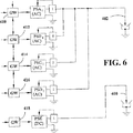
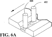
本発明はいずれの数の電極を含めて説明することができる。三つの電極350、352および354を図5および図5Aに示す。これまでに説明したネットワーク360は図1に示したシステムSと二つの付加的なシステム370、372と連絡している。ネットワーク360はロジックを図1に示したゲートウエイ50と52を介して同様のゲートウエイ380と382と一緒に制御する。本発明のこの実施例は一つの電極356を介して同期化され、かつ、時計測されたAC電流を提供する二つの電源PSAとPSBを示している。電極352はゲートウエイ380によってネットワーク360に接続されているので電源PSCは単一のマスターのみを使用して電極352のためのAC電流を形成している。電極354は、出力極性スイッチがなく、かつ、ネットワーク360によってゲートウエイ382を介して駆動されるDC電源である電源PSDによって駆動される。他の構成が異なるタンデム電極プロセスのアーキテクチャを構築するのに使用される。例えば、二つの電極400、402が図6および図6Aのレイアウトに示される。四つの別々の電源PSA1、PSB1、PSC1およびPSD1が並列接続されAC電流を電極402の両端に生成している。電源PSEは出力極性スイッチのないDC電源である。全ての電源はそれぞれゲートウエイまたはネットワークインターフェースカード410、412、414、416および418を備えている。各ゲートウエイは個々の電源のためのパラメータを受信する。ゲートウエイ410〜416は相互接続され、最初の四つの電源中のスイッチのタイミングと極性が正確に相互関係にあることを補償している。ゲートウエイ414、416がゲートウエイ412と直列で駆動されるように指示されているが、実際にはこれらは並列状態でゲートウエイ410の出力から直接駆動される。これが個々のゲートウエイ中のタイミング差の累積を阻止している。
The present invention can be described including any number of electrodes. Three
説明したように、マスターおよびスレーブ電源の切換点は実際に切換シーケンスであり、そのインバータが最初にオフされ、次にスイッチが切り換えられ、電源が低電流に到達した後で極性が変えられる。インバータがオフされたときに、電流が低下される。従って、極性の反転が実行される。このコンセプトはスタバ特許6,111,216号に開示されている。本発明の切換技術は図7および7Aに示されており、AC電流曲線を有する二つの電極420、422が曲線424と曲線426で概略的に示されている。曲線424において、電源は点430でオフされる。電流が低電流レベル423に下り、この時点で負極性に反転する。この負電流レベルが所望のパラメータに到達するまで持続する。次に電源が点434でオフされ、負電流パルスが切換点436まで低下し、この時点でスイッチが正極性に反転する。一つのマスター電源および一つまたはそれ以上のスレーブ電源で、キル点430、434が対等であり、さらに切換点ないし時間432、436においても対等なことが必要である。簡単に説明するために、この極性反転シーケンスは「切換時間」と呼ぶ。曲線426は距離eだけオフセットしており、直列接続された一つまたはそれ以上の電源によってもたらされる。この曲線は電源キル点440とキル点444を有している。切換点442、446電流切換点432、436に対応している。図7Aに説明された技術が好ましいけれども、切換点における直流反転も本発明で使用できる。この場合において、スイッチは大型になり、かつ緩衝型ネットワークないしスイッチと並列にある大型緩衝型ネットワークでなければならない。
As explained, the switching point of the master and slave power supply is actually a switching sequence, the inverter is first turned off, then the switch is switched, and the polarity is changed after the power supply reaches low current. When the inverter is turned off, the current is reduced. Therefore, polarity inversion is performed. This concept is disclosed in Starbah Patent 6,111,216. The switching technique of the present invention is illustrated in FIGS. 7 and 7A, where two
説明したように、マスター制御装置がスイッチされると、スイッチ命令がマスター制御装置に発せられる。これが「キル」信号となりマスターによって受信され、これによってキル信号と極性ロジックが、単一電極に並列接続された一つまたはそれ以上のスレーブ電源のコントローラに迅速に伝送される。標準AC電源が極性スイッチと並列にある大型緩衝器と併用されれば、マスター電源がスイッチ命令を受信した後、スレーブコントローラまたは複数のコントローラが1〜10μs内に直ちに切り換えられる。これが高精度インターフェースカードないしゲートウエイの利点である。実際に、並列接続電源の電流反転のための実際の切り換えは、出力電流が任意の値、すなわち、約100アンペア未満になるまで、発生しない。これがより小さいスイッチの使用を許容している。 As explained, when the master controller is switched, a switch command is issued to the master controller. This becomes a “kill” signal and is received by the master, which quickly transmits the kill signal and polarity logic to the controller of one or more slave power supplies connected in parallel to a single electrode. If a standard AC power supply is used in conjunction with a large buffer in parallel with the polarity switch, the slave controller or controllers are immediately switched within 1-10 μs after the master power supply receives the switch command. This is the advantage of a high-precision interface card or gateway. Indeed, the actual switching for current reversal of the parallel connected power supply does not occur until the output current is at an arbitrary value, i.e. less than about 100 amps. This allows the use of smaller switches.
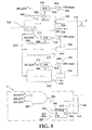
この遅延切換方法を使用する本発明の実行には、全ての電源が任意の低電流レベル以下になった後でのみ実際の切換えが必要となる。遅延プロセスはデジタルプロセッサのソフトウエアで達成され、図8の概略レイアウトによって示される。マスター電源500のコントローラが線502によって表わされた命令信号を受信したときに、電源が切換シーケンスを開始する。マスターが線504にロジックを出力し、スレーブの切換のために所望の極性を提供しマスターの極性切換に対応させる。命令された切換シーケンスにおいて、マスター電源500のインバータがオフされるか、電極Eの電流がホール効果トランスデューサ510によって読み取られるように低下される。線502の切換命令は線512によって表わされた直接の「キル」信号をして並列スレーブ電極520、522のコントローラに対してホール効果トランスデューサ532、534によって測定された電流を接続点530に提供せしめる。全ての電源はインバータのオフないしダウンでスイッチシーケンスにある。ソフトウエア比較回路550、552、554が低下電流を線556上の電圧に関連する任意の低電流と比較する。各電源が任意の値未満に低下すると、信号がそれぞれサンプル/ホールド回路570、572および574の入力への線560、562および564に現われる。これらの回路は電源の各々から線580中のストロボ信号を受信する。セットロジックが回路570、572および574内に記憶されると、YESロジックがストロボ信号の時間で線READY1、READY2、およびREADY3 上に現われる。この信号は電源に発生されるとともに25μsの周期を有しているが、他の高速ストロボも使用することができる。信号は図8の破線で示したマスター電源のコントローラCに向けられる。ANDゲート580によって表わされたソフトウエアのAND操作機能は、全ての電源が極性を切り換える用意がなされたときに、線582上のYESロジック出力を有する。この出力条件はソフトウエアフリップフロップ600のクロックイネーブル端子ECLKに向けられる。このフリップフロップはそのD端子を有しており線504に現われる切り換えられるべき極性の所望のロジックを備えている。約1MHzで作動されるオッシレータないしタイマーが端子CKへの線602上の信号によってフリップフロップをクロックする。これが線504上の極性命令ロジックをQ端子604に転送し、線610にこのロジックを提供してスレーブ520、522を切り換え、これと同時に線612上の同様のロジックがマスター電源500を切り換える。切り換え後、線504上の極性ロジックが対向極性にシフトし、一方マスター電源が切換周波数に基づいた次の切換命令を待機する。他の回路が切換シーケンス中の遅延を実行するのに使用できるが、図8の説明は本実施例の態様である。
Implementation of the present invention using this delay switching method requires actual switching only after all power supplies are below any low current level. The delay process is accomplished with digital processor software and is illustrated by the schematic layout of FIG. When the controller of
インターフェースタイミングは10μs未満と説明されている。この値はイーサネット(登録商標)精度よりも実質的に精度が高くなる。従って、約100μs程度であり、なお利点を提供する。しかし、対等スイッチ操作は25μsのREADYストロボで約10μs未満の精度で容易になる。各電源は切換命令が発生される前に極性の切換えが容易である。一つが準備完了前に電流低下し、他方が準備完了電流に低下すると、元に戻ることができる。キーとなるのは正確な制御と低電流での切換えである。付加的に、電源は正確なインターフェースによる反転極性チョッパの正状態を有する背中合わせの反転極性チョッパとなる。背中合わせのACチョッパは2000年5月22日出願の先行米国特許願第09/575,264号に開示されており、ここでは参照例として一体化する。 The interface timing is described as less than 10 μs. This value is substantially higher than Ethernet (registered trademark) accuracy. Thus, it is on the order of about 100 μs and still provides an advantage. However, peer switch operation is facilitated with an accuracy of less than about 10 μs with a 25 μs READY strobe. Each power supply can be easily switched in polarity before a switching command is generated. When one drops to current before preparation is complete and the other drops to preparation current, it can be restored. The key is accurate control and low current switching. Additionally, the power supply becomes a back-to-back inverted polarity chopper with the positive state of the inverted polarity chopper with a precise interface. A back-to-back AC chopper is disclosed in prior US patent application Ser. No. 09 / 575,264 filed May 22, 2000, which is hereby incorporated by reference.
Claims (13)
第1の時間に前記電極と工作物間の第1AC電流の極性を反転させる第1切換制御信号を発生することによって、第1溶接パラメータを伴う第1AC電流を生成する第1電源と、
第2の時間に前記電極と工作物間の第2AC電流の極性を反転させる第2切換制御信号によって、第2溶接パラメータを伴う第2AC電流を生成する第2電源と、
前記第1切換制御信号によって前記第2切換制御信号を生成する前記第1電源と第2電源間に設けたタイミングインターフェースとからなることを特徴とするアーク溶接システム。An arc welding system for generating an AC welding arc between an electrode and a workpiece,
A first power source that generates a first AC current with a first welding parameter by generating a first switching control signal that reverses the polarity of the first AC current between the electrode and the workpiece at a first time;
A second power source that generates a second AC current with a second welding parameter by a second switching control signal that reverses the polarity of the second AC current between the electrode and the workpiece at a second time;
An arc welding system comprising: a timing interface provided between the first power source and the second power source that generates the second switching control signal according to the first switching control signal.
Applications Claiming Priority (2)
| Application Number | Priority Date | Filing Date | Title |
|---|---|---|---|
| US09/835,972 US6472634B1 (en) | 2001-04-17 | 2001-04-17 | Electric arc welding system |
| PCT/US2002/007432 WO2002083351A1 (en) | 2001-04-17 | 2002-03-08 | Electric arc welding system |
Publications (3)
| Publication Number | Publication Date |
|---|---|
| JP2004524161A JP2004524161A (en) | 2004-08-12 |
| JP2004524161A5 JP2004524161A5 (en) | 2005-08-04 |
| JP4532073B2 true JP4532073B2 (en) | 2010-08-25 |
Family
ID=25270917
Family Applications (1)
| Application Number | Title | Priority Date | Filing Date |
|---|---|---|---|
| JP2002581138A Expired - Lifetime JP4532073B2 (en) | 2001-04-17 | 2002-03-08 | Arc welding system |
Country Status (15)
| Country | Link |
|---|---|
| US (4) | US6472634B1 (en) |
| EP (1) | EP1387732B2 (en) |
| JP (1) | JP4532073B2 (en) |
| KR (1) | KR100592356B1 (en) |
| CN (2) | CN1329157C (en) |
| AT (1) | ATE508829T1 (en) |
| AU (1) | AU2002252295B2 (en) |
| DK (1) | DK1387732T3 (en) |
| EG (1) | EG22920A (en) |
| RU (1) | RU2275280C2 (en) |
| SA (1) | SA02230117B1 (en) |
| TW (1) | TWI270433B (en) |
| UA (1) | UA74884C2 (en) |
| WO (1) | WO2002083351A1 (en) |
| ZA (1) | ZA200307589B (en) |
Families Citing this family (109)
| Publication number | Priority date | Publication date | Assignee | Title |
|---|---|---|---|---|
| US20030149368A1 (en) * | 2000-10-24 | 2003-08-07 | Hennemann Willard W. | Method and apparatus for locating and detecting vascular plaque via impedence and conductivity measurements, and for cryogenically passivating vascular plaque and inhibiting vascular plaque progression and rupture |
| US6472634B1 (en) * | 2001-04-17 | 2002-10-29 | Lincoln Global, Inc. | Electric arc welding system |
| US6504131B1 (en) | 2001-09-19 | 2003-01-07 | Illinois Tool Works Inc. | Welding-type power supply with boot loader |
| US6815640B1 (en) * | 2002-07-09 | 2004-11-09 | Lincoln Global, Inc. | Apparatus, system and method to facilitate reconfigurable welding power supply |
| US6984806B2 (en) * | 2002-07-23 | 2006-01-10 | Illinois Tool Works Inc. | Method and apparatus for retracting and advancing a welding wire |
| US6969823B2 (en) * | 2002-07-23 | 2005-11-29 | Illinois Tool Works Inc. | Method and apparatus for controlling a welding system |
| US7165707B2 (en) * | 2002-07-23 | 2007-01-23 | Illinois Tool Works Inc. | Method and apparatus for feeding wire to a welding arc |
| US6963048B2 (en) * | 2002-07-23 | 2005-11-08 | Illinois Tool Works Inc. | Method and apparatus for welding with mechanical arc control |
| US7102099B2 (en) * | 2002-07-23 | 2006-09-05 | Illinois Tool Works Inc. | Method and apparatus for feeding wire to a welding arc |
| US8129297B2 (en) * | 2002-07-29 | 2012-03-06 | E. I. Du Pont De Nemours And Company | Method and apparatus for heating nonwoven webs |
| US6847008B2 (en) * | 2003-01-17 | 2005-01-25 | Lincoln Global, Inc. | Electric arc welding system |
| US7105772B2 (en) * | 2003-03-24 | 2006-09-12 | Lincoln Global, Inc. | Arc welding system and method |
| US7274000B2 (en) * | 2003-07-11 | 2007-09-25 | Lincoln Global, Inc. | Power source for high current welding |
| US7064290B2 (en) * | 2003-09-08 | 2006-06-20 | Lincoln Global, Inc. | Electric arc welder and method for controlling the welding process of the welder |
| US7091446B2 (en) * | 2003-12-15 | 2006-08-15 | Lincoln Global, Inc. | Electric arc welding system |
| US6940039B2 (en) * | 2003-12-22 | 2005-09-06 | Lincoln Global, Inc. | Quality control module for tandem arc welding |
| US7105773B2 (en) | 2004-01-12 | 2006-09-12 | Lincoln Global, Inc. | Electric arc welder |
| US8895896B2 (en) * | 2004-01-12 | 2014-11-25 | Lincoln Global, Inc. | Modified series arc welding and improved control of one sided series arc welding |
| US7053334B2 (en) * | 2004-03-01 | 2006-05-30 | Lincoln Global, Inc. | Electric arc welder system with waveform profile control |
| US7842903B2 (en) * | 2005-10-31 | 2010-11-30 | Lincoln Global, Inc. | Short arc welding system |
| US9333580B2 (en) * | 2004-04-29 | 2016-05-10 | Lincoln Global, Inc. | Gas-less process and system for girth welding in high strength applications |
| US8704135B2 (en) | 2006-01-20 | 2014-04-22 | Lincoln Global, Inc. | Synergistic welding system |
| US8759715B2 (en) | 2004-10-06 | 2014-06-24 | Lincoln Global, Inc. | Method of AC welding with cored electrode |
| US20070221643A1 (en) * | 2004-04-29 | 2007-09-27 | Lincoln Global, Inc. | Gas-less process and system for girth welding in high strength applications including liquefied natural gas storage tanks |
| US7166817B2 (en) * | 2004-04-29 | 2007-01-23 | Lincoln Global, Inc. | Electric ARC welder system with waveform profile control for cored electrodes |
| US7208711B2 (en) * | 2004-05-14 | 2007-04-24 | Coolhead Technologies, Inc. | Dielectric welding methods and apparatus |
| US8269141B2 (en) | 2004-07-13 | 2012-09-18 | Lincoln Global, Inc. | Power source for electric arc welding |
| US8581147B2 (en) | 2005-03-24 | 2013-11-12 | Lincoln Global, Inc. | Three stage power source for electric ARC welding |
| US8785816B2 (en) | 2004-07-13 | 2014-07-22 | Lincoln Global, Inc. | Three stage power source for electric arc welding |
| US9956639B2 (en) | 2005-02-07 | 2018-05-01 | Lincoln Global, Inc | Modular power source for electric ARC welding and output chopper |
| US9855620B2 (en) | 2005-02-07 | 2018-01-02 | Lincoln Global, Inc. | Welding system and method of welding |
| US7495193B2 (en) * | 2005-03-15 | 2009-02-24 | Lincoln Global, Inc. | Pipe seam tack welding methods and apparatus using modified series arc welding |
| US7968822B2 (en) * | 2005-03-28 | 2011-06-28 | Lincoln Global, Inc. | Arc welding system |
| US9647555B2 (en) | 2005-04-08 | 2017-05-09 | Lincoln Global, Inc. | Chopper output stage for arc welder power source |
| US20060231540A1 (en) * | 2005-04-19 | 2006-10-19 | Lincoln Global, Inc. | Method and apparatus for short-circuit welding |
| US8680432B2 (en) * | 2005-04-20 | 2014-03-25 | Illinois Tool Works Inc. | Cooperative welding system |
| US7989732B2 (en) * | 2005-06-15 | 2011-08-02 | Lincoln Global, Inc. | Method of AC welding using a flux cored electrode |
| US8952291B2 (en) * | 2005-09-15 | 2015-02-10 | Lincoln Global, Inc. | System and method for controlling a hybrid welding process |
| FR2896716B1 (en) * | 2006-01-31 | 2009-06-26 | Abb Mc Soc Par Actions Simplif | METHOD FOR CONTROLLING A ROBOTIZED WORK STATION AND CORRESPONDING ROBOTIC STATION |
| US7457139B2 (en) * | 2006-03-20 | 2008-11-25 | Sansha Electric Manufacturing Company, Limited | Power supply apparatus for arc-utilizing apparatuses |
| US8242410B2 (en) | 2006-07-14 | 2012-08-14 | Lincoln Global, Inc. | Welding methods and systems |
| US20080011727A1 (en) * | 2006-07-14 | 2008-01-17 | Lincoln Global, Inc. | Dual fillet welding methods and systems |
| US9095929B2 (en) | 2006-07-14 | 2015-08-04 | Lincoln Global, Inc. | Dual fillet welding methods and systems |
| US10010961B2 (en) * | 2006-07-17 | 2018-07-03 | Lincoln Global, Inc. | Multiple arc welding system controls and methods |
| AT504197B1 (en) | 2006-09-08 | 2010-01-15 | Fronius Int Gmbh | WELDING METHOD FOR CARRYING OUT A WELDING PROCESS |
| US20080078811A1 (en) * | 2006-09-15 | 2008-04-03 | The Lincoln Electric Company | Weld data acquisition |
| US8963045B2 (en) * | 2006-09-19 | 2015-02-24 | Lincoln Global, Inc. | Non-linear adaptive control system and method for welding |
| US8946596B2 (en) | 2006-10-05 | 2015-02-03 | Lincoln Global, Inc. | Multiple welding using a single power source |
| SE531142C2 (en) * | 2007-05-11 | 2009-01-07 | Esab Ab | Welding power units, procedure and computer software product |
| KR100841422B1 (en) * | 2007-05-22 | 2008-06-25 | (주)종합기계 | Apparatus for welding the inside of workpiece |
| US9044818B2 (en) * | 2007-11-08 | 2015-06-02 | Lincoln Global, Inc. | Method of welding two sides of a joint simultaneously |
| US8952293B2 (en) * | 2008-03-14 | 2015-02-10 | Illinois Tool Works Inc. | Welding or cutting power supply using phase shift double forward converter circuit (PSDF) |
| WO2010038779A1 (en) * | 2008-09-30 | 2010-04-08 | 高周波熱錬株式会社 | Welding device for metal and welding method for metal |
| WO2010098030A1 (en) * | 2009-02-25 | 2010-09-02 | パナソニック株式会社 | Welding method and welding system |
| US10500667B2 (en) * | 2009-04-08 | 2019-12-10 | Panasonic Intellectual Property Management Co., Ltd. | Arc welding method and arc welding apparatus for adjusting a welding current waveform responsive to a setting voltage adjustment |
| US8330077B2 (en) * | 2009-09-03 | 2012-12-11 | Illinois Tool Works Inc. | Remote welding system and method |
| SE534975C2 (en) * | 2009-10-16 | 2012-03-06 | Tsc Innovation Ab | Method and apparatus for installing and repairing insulated pipe lines |
| JP5466484B2 (en) * | 2009-11-06 | 2014-04-09 | 株式会社神戸製鋼所 | Arc welding system, single arc welding system and tandem arc welding system |
| CN102448651B (en) * | 2009-11-25 | 2014-07-30 | 松下电器产业株式会社 | Welding method and welding device |
| CN102448652B (en) * | 2010-03-01 | 2015-02-11 | 松下电器产业株式会社 | Alternating-current arc welding device |
| US20110240620A1 (en) | 2010-04-05 | 2011-10-06 | Illinois Tool Works Inc. | Welding system and method utilizing internal ethernet communications |
| US9162308B2 (en) * | 2010-10-22 | 2015-10-20 | Lincoln Global, Inc. | Apparatus and method for pulse welding with AC waveform |
| US9180545B2 (en) * | 2010-12-21 | 2015-11-10 | Lincoln Global, Inc. | Wire feeder with electrode power routing |
| CN102069265B (en) * | 2010-12-23 | 2012-08-22 | 哈尔滨工业大学 | Dynamic twin-wire three-arc welding method |
| US9403231B2 (en) * | 2011-11-09 | 2016-08-02 | Illinois Tool Works Inc. | Hybrid pulsed-short circuit welding regime |
| US20130119037A1 (en) * | 2011-11-11 | 2013-05-16 | Lincoln Global, Inc. | Systems and methods for utilizing welder power source data |
| CN102528227A (en) * | 2012-03-01 | 2012-07-04 | 天津大学 | Welding equipment network monitoring device and control method thereof |
| US9566657B2 (en) * | 2012-03-27 | 2017-02-14 | Illinois Tool Works Inc. | System and method for determining attachment and polarity of a welding electrode |
| US10040143B2 (en) | 2012-12-12 | 2018-08-07 | Illinois Tool Works Inc. | Dabbing pulsed welding system and method |
| US10906114B2 (en) | 2012-12-21 | 2021-02-02 | Illinois Tool Works Inc. | System for arc welding with enhanced metal deposition |
| US9950383B2 (en) | 2013-02-05 | 2018-04-24 | Illinois Tool Works Inc. | Welding wire preheating system and method |
| US10376980B2 (en) * | 2013-03-08 | 2019-08-13 | Lincoln Global, Inc. | Arc welding with synchronized high frequency assist arc initiation |
| US9221116B2 (en) * | 2013-03-11 | 2015-12-29 | Lincoln Global, Inc. | Inductive discharge arc re-ignition and stabilizing circuit |
| US10835983B2 (en) | 2013-03-14 | 2020-11-17 | Illinois Tool Works Inc. | Electrode negative pulse welding system and method |
| US9610646B2 (en) | 2013-05-15 | 2017-04-04 | Illinois Tool Works Inc. | Polarity changing pin connector |
| RU2517199C1 (en) * | 2013-06-05 | 2014-05-27 | Федеральное государственное бюджетное образовательное учреждение высшего профессионального образования "Мордовский государственный университет им. Н.П. Огарева" | Method to arrange grouped operation of reversible converters |
| JP6139285B2 (en) * | 2013-06-13 | 2017-05-31 | 株式会社ダイヘン | Arc welding machine |
| US11045891B2 (en) | 2013-06-13 | 2021-06-29 | Illinois Tool Works Inc. | Systems and methods for anomalous cathode event control |
| US10828728B2 (en) | 2013-09-26 | 2020-11-10 | Illinois Tool Works Inc. | Hotwire deposition material processing system and method |
| CN103862139B (en) * | 2014-03-24 | 2015-07-08 | 深圳市佳士科技股份有限公司 | Output control circuit with storage battery for electric welding machine |
| US11154946B2 (en) | 2014-06-30 | 2021-10-26 | Illinois Tool Works Inc. | Systems and methods for the control of welding parameters |
| US11198189B2 (en) | 2014-09-17 | 2021-12-14 | Illinois Tool Works Inc. | Electrode negative pulse welding system and method |
| US10173279B2 (en) * | 2014-11-21 | 2019-01-08 | Lincoln Global, Inc. | Welding system |
| US11478870B2 (en) | 2014-11-26 | 2022-10-25 | Illinois Tool Works Inc. | Dabbing pulsed welding system and method |
| US10189106B2 (en) | 2014-12-11 | 2019-01-29 | Illinois Tool Works Inc. | Reduced energy welding system and method |
| US11370050B2 (en) | 2015-03-31 | 2022-06-28 | Illinois Tool Works Inc. | Controlled short circuit welding system and method |
| US11285559B2 (en) | 2015-11-30 | 2022-03-29 | Illinois Tool Works Inc. | Welding system and method for shielded welding wires |
| US10610946B2 (en) | 2015-12-07 | 2020-04-07 | Illinois Tool Works, Inc. | Systems and methods for automated root pass welding |
| US10675699B2 (en) | 2015-12-10 | 2020-06-09 | Illinois Tool Works Inc. | Systems, methods, and apparatus to preheat welding wire |
| EP3427882B1 (en) | 2016-03-11 | 2020-11-25 | Daihen Corporation | Arc welding system and wire-feeding device |
| JP6650838B2 (en) | 2016-06-23 | 2020-02-19 | 株式会社ダイヘン | Power supply system, power supply, control method, and control program |
| US10532417B2 (en) | 2016-08-08 | 2020-01-14 | Lincoln Global, Inc. | Dual battery hybrid engine drive welding power supply |
| US10766092B2 (en) | 2017-04-18 | 2020-09-08 | Illinois Tool Works Inc. | Systems, methods, and apparatus to provide preheat voltage feedback loss protection |
| US10870164B2 (en) | 2017-05-16 | 2020-12-22 | Illinois Tool Works Inc. | Systems, methods, and apparatus to preheat welding wire |
| WO2018227195A1 (en) | 2017-06-09 | 2018-12-13 | Illinois Tool Works Inc. | Welding torch with a first contact tip to preheat welding wire and a second contact tip |
| EP3634683B1 (en) | 2017-06-09 | 2022-03-23 | Illinois Tool Works, Inc. | Welding assembly for a welding torch, with two contact tips and a cooling body to cool and conduct current |
| US11524354B2 (en) | 2017-06-09 | 2022-12-13 | Illinois Tool Works Inc. | Systems, methods, and apparatus to control weld current in a preheating system |
| CN111315524A (en) | 2017-06-09 | 2020-06-19 | 伊利诺斯工具制品有限公司 | Welding torch having two contacts and multiple liquid cooled assemblies for conducting current to the contacts |
| US11590598B2 (en) | 2017-06-09 | 2023-02-28 | Illinois Tool Works Inc. | Systems, methods, and apparatus to preheat welding wire |
| JP6835676B2 (en) | 2017-07-05 | 2021-02-24 | 株式会社ダイヘン | Power system, power supply, control method and control program |
| US11498148B2 (en) | 2017-09-07 | 2022-11-15 | Illinois Tool Works Inc. | Methods and apparatus to synergically control a welding-type output during a welding-type operation |
| US11020813B2 (en) | 2017-09-13 | 2021-06-01 | Illinois Tool Works Inc. | Systems, methods, and apparatus to reduce cast in a welding wire |
| WO2020047438A1 (en) | 2018-08-31 | 2020-03-05 | Illinois Tool Works Inc. | Submerged arc welding systems and submerged arc welding torches to resistively preheat electrode wire |
| US11014185B2 (en) | 2018-09-27 | 2021-05-25 | Illinois Tool Works Inc. | Systems, methods, and apparatus for control of wire preheating in welding-type systems |
| CN113474113A (en) | 2018-12-19 | 2021-10-01 | 伊利诺斯工具制品有限公司 | Contact tip, wire preheating assembly, contact tip assembly and consumable electrode feed welding-type system |
| US10710310B1 (en) * | 2019-08-15 | 2020-07-14 | Dukane Ias, Llc | Multipoint controllers for power delivery to multiple probes in ultrasonic welding systems |
| US11772182B2 (en) | 2019-12-20 | 2023-10-03 | Illinois Tool Works Inc. | Systems and methods for gas control during welding wire pretreatments |
| US11919110B2 (en) | 2020-07-21 | 2024-03-05 | Esab Ab | Balance and offset in adaptive submerged arc welding |
| RU2759350C1 (en) * | 2021-02-01 | 2021-11-12 | Общество с ограниченной ответственностью "ШТОРМ" | Method for electric arc welding of non-rotary annular pipeline seams |
Family Cites Families (18)
| Publication number | Priority date | Publication date | Assignee | Title |
|---|---|---|---|---|
| US3300683A (en) | 1964-01-06 | 1967-01-24 | Boeing Co | Welding apparatus |
| US3458797A (en) * | 1967-08-15 | 1969-07-29 | Trw Inc | Inverter circuit for supplying a sine wave substantially free of harmonics |
| US3637973A (en) * | 1969-02-19 | 1972-01-25 | Mitsubishi Electric Corp | Arc welding apparatus |
| JPS56111578A (en) * | 1980-02-07 | 1981-09-03 | Nippon Steel Corp | Gas shielded arc welding method using alternating current multiple electrode |
| US4425613A (en) * | 1981-05-26 | 1984-01-10 | Sperry Corporation | Forced load sharing circuit for inverter power supply |
| US4503316A (en) * | 1981-08-13 | 1985-03-05 | Kabushiki Kaisha Kobe Seiko Sho | DC Welding power supply system |
| JPS5829574A (en) * | 1981-08-13 | 1983-02-21 | Murase Kogyo Kk | Electric power source device for short circuit transfer welding |
| US4985612A (en) † | 1987-12-15 | 1991-01-15 | Kabushiki Kaisha Toshiba | Master computer controlled modular welder, weld control, and power unit apparatus and method |
| EP0585068B1 (en) * | 1992-08-25 | 1998-04-15 | Matsushita Electric Industrial Co., Ltd. | Arc welding machine and plasma cutting machine |
| US6051810A (en) * | 1998-01-09 | 2000-04-18 | Lincoln Global, Inc. | Short circuit welder |
| US6023037A (en) | 1998-11-05 | 2000-02-08 | Lincoln Global, Inc. | Electric ARC welder and plasma cutter |
| US6207929B1 (en) | 1999-06-21 | 2001-03-27 | Lincoln Global, Inc. | Tandem electrode welder and method of welding with two electrodes |
| US6310320B1 (en) † | 1999-01-07 | 2001-10-30 | Illinois Tool Works Inc. | Dual operator phase control engine driven welder |
| US6111216A (en) | 1999-01-19 | 2000-08-29 | Lincoln Global, Inc. | High current welding power supply |
| US6291798B1 (en) * | 1999-09-27 | 2001-09-18 | Lincoln Global, Inc. | Electric ARC welder with a plurality of power supplies |
| DE10060429A1 (en) * | 1999-12-16 | 2001-07-12 | Caterpillar Inc | Power transmitter; has control circuit to transmit n instruction signals to n power converter circuits, which are driven to transfer n pulse width modulated signals out of phase by 360/n degrees |
| US6365874B1 (en) * | 2000-05-22 | 2002-04-02 | Lincoln Global, Inc. | Power supply for electric arc welding |
| US6472634B1 (en) | 2001-04-17 | 2002-10-29 | Lincoln Global, Inc. | Electric arc welding system |
-
2001
- 2001-04-17 US US09/835,972 patent/US6472634B1/en not_active Expired - Lifetime
-
2002
- 2002-03-08 JP JP2002581138A patent/JP4532073B2/en not_active Expired - Lifetime
- 2002-03-08 RU RU2003133298/02A patent/RU2275280C2/en not_active IP Right Cessation
- 2002-03-08 AT AT02721359T patent/ATE508829T1/en active
- 2002-03-08 KR KR1020037013490A patent/KR100592356B1/en not_active IP Right Cessation
- 2002-03-08 CN CNB028082265A patent/CN1329157C/en not_active Expired - Lifetime
- 2002-03-08 AU AU2002252295A patent/AU2002252295B2/en not_active Ceased
- 2002-03-08 DK DK02721359.4T patent/DK1387732T3/en active
- 2002-03-08 WO PCT/US2002/007432 patent/WO2002083351A1/en active IP Right Grant
- 2002-03-08 CN CN2007101091510A patent/CN101062530B/en not_active Expired - Lifetime
- 2002-03-08 EP EP02721359.4A patent/EP1387732B2/en not_active Expired - Lifetime
- 2002-03-28 TW TW091106150A patent/TWI270433B/en not_active IP Right Cessation
- 2002-03-31 EG EG20020340A patent/EG22920A/en active
- 2002-05-21 SA SA02230117A patent/SA02230117B1/en unknown
- 2002-08-03 UA UA20031110318A patent/UA74884C2/en unknown
- 2002-09-06 US US10/236,836 patent/US6660966B2/en not_active Expired - Lifetime
-
2003
- 2003-09-29 ZA ZA200307589A patent/ZA200307589B/en unknown
- 2003-11-06 US US10/702,278 patent/US6855912B2/en not_active Expired - Lifetime
-
2004
- 2004-09-03 US US10/933,659 patent/US6940040B2/en not_active Expired - Lifetime
Also Published As
| Publication number | Publication date |
|---|---|
| US20050023253A1 (en) | 2005-02-03 |
| SA02230117B1 (en) | 2007-07-31 |
| US6472634B1 (en) | 2002-10-29 |
| DK1387732T3 (en) | 2011-08-15 |
| AU2002252295B2 (en) | 2005-11-03 |
| US20030006222A1 (en) | 2003-01-09 |
| EP1387732A4 (en) | 2008-03-19 |
| RU2275280C2 (en) | 2006-04-27 |
| EP1387732B2 (en) | 2018-06-20 |
| US6660966B2 (en) | 2003-12-09 |
| KR100592356B1 (en) | 2006-06-22 |
| EP1387732A1 (en) | 2004-02-11 |
| KR20040022418A (en) | 2004-03-12 |
| UA74884C2 (en) | 2006-02-15 |
| TWI270433B (en) | 2007-01-11 |
| US6855912B2 (en) | 2005-02-15 |
| RU2003133298A (en) | 2005-05-10 |
| EG22920A (en) | 2003-11-30 |
| JP2004524161A (en) | 2004-08-12 |
| CN1610594A (en) | 2005-04-27 |
| CN1329157C (en) | 2007-08-01 |
| ZA200307589B (en) | 2004-06-29 |
| EP1387732B1 (en) | 2011-05-11 |
| US6940040B2 (en) | 2005-09-06 |
| CN101062530A (en) | 2007-10-31 |
| WO2002083351A1 (en) | 2002-10-24 |
| US20040065650A1 (en) | 2004-04-08 |
| EP1387732B8 (en) | 2012-03-21 |
| ATE508829T1 (en) | 2011-05-15 |
| CN101062530B (en) | 2011-07-06 |
Similar Documents
| Publication | Publication Date | Title |
|---|---|---|
| JP4532073B2 (en) | Arc welding system | |
| AU2002252295A1 (en) | Electric arc welding system | |
| US6847008B2 (en) | Electric arc welding system | |
| US7282668B2 (en) | Electric arc welding system | |
| US7358459B2 (en) | Electric arc welder system with waveform profile control | |
| KR100654280B1 (en) | Electric arc welding apparatus, method of changing polarity of the welding current and apparatus thereof | |
| AU2006200414B2 (en) | Electric arc welding system | |
| JPH0332296B2 (en) |
Legal Events
| Date | Code | Title | Description |
|---|---|---|---|
| A131 | Notification of reasons for refusal |
Free format text: JAPANESE INTERMEDIATE CODE: A131 Effective date: 20071009 |
|
| A521 | Request for written amendment filed |
Free format text: JAPANESE INTERMEDIATE CODE: A523 Effective date: 20080107 |
|
| A131 | Notification of reasons for refusal |
Free format text: JAPANESE INTERMEDIATE CODE: A131 Effective date: 20090714 |
|
| A601 | Written request for extension of time |
Free format text: JAPANESE INTERMEDIATE CODE: A601 Effective date: 20091014 |
|
| A602 | Written permission of extension of time |
Free format text: JAPANESE INTERMEDIATE CODE: A602 Effective date: 20091021 |
|
| A521 | Request for written amendment filed |
Free format text: JAPANESE INTERMEDIATE CODE: A523 Effective date: 20091112 |
|
| TRDD | Decision of grant or rejection written | ||
| A01 | Written decision to grant a patent or to grant a registration (utility model) |
Free format text: JAPANESE INTERMEDIATE CODE: A01 Effective date: 20100511 |
|
| A01 | Written decision to grant a patent or to grant a registration (utility model) |
Free format text: JAPANESE INTERMEDIATE CODE: A01 |
|
| A61 | First payment of annual fees (during grant procedure) |
Free format text: JAPANESE INTERMEDIATE CODE: A61 Effective date: 20100610 |
|
| R150 | Certificate of patent or registration of utility model |
Ref document number: 4532073 Country of ref document: JP Free format text: JAPANESE INTERMEDIATE CODE: R150 Free format text: JAPANESE INTERMEDIATE CODE: R150 |
|
| FPAY | Renewal fee payment (event date is renewal date of database) |
Free format text: PAYMENT UNTIL: 20130618 Year of fee payment: 3 |
|
| R250 | Receipt of annual fees |
Free format text: JAPANESE INTERMEDIATE CODE: R250 |
|
| R250 | Receipt of annual fees |
Free format text: JAPANESE INTERMEDIATE CODE: R250 |
|
| R250 | Receipt of annual fees |
Free format text: JAPANESE INTERMEDIATE CODE: R250 |
|
| R250 | Receipt of annual fees |
Free format text: JAPANESE INTERMEDIATE CODE: R250 |
|
| R250 | Receipt of annual fees |
Free format text: JAPANESE INTERMEDIATE CODE: R250 |
|
| R250 | Receipt of annual fees |
Free format text: JAPANESE INTERMEDIATE CODE: R250 |
|
| R250 | Receipt of annual fees |
Free format text: JAPANESE INTERMEDIATE CODE: R250 |
|
| R250 | Receipt of annual fees |
Free format text: JAPANESE INTERMEDIATE CODE: R250 |
|
| R250 | Receipt of annual fees |
Free format text: JAPANESE INTERMEDIATE CODE: R250 |
|
| EXPY | Cancellation because of completion of term |