JP4531165B2 - Progressive addition lens - Google Patents
Progressive addition lens Download PDFInfo
- Publication number
- JP4531165B2 JP4531165B2 JP24923399A JP24923399A JP4531165B2 JP 4531165 B2 JP4531165 B2 JP 4531165B2 JP 24923399 A JP24923399 A JP 24923399A JP 24923399 A JP24923399 A JP 24923399A JP 4531165 B2 JP4531165 B2 JP 4531165B2
- Authority
- JP
- Japan
- Prior art keywords
- lens
- progressive addition
- refractive power
- optical elements
- diopters
- Prior art date
- Legal status (The legal status is an assumption and is not a legal conclusion. Google has not performed a legal analysis and makes no representation as to the accuracy of the status listed.)
- Expired - Lifetime
Links
Images


Classifications
-
- G—PHYSICS
- G02—OPTICS
- G02C—SPECTACLES; SUNGLASSES OR GOGGLES INSOFAR AS THEY HAVE THE SAME FEATURES AS SPECTACLES; CONTACT LENSES
- G02C7/00—Optical parts
- G02C7/02—Lenses; Lens systems ; Methods of designing lenses
- G02C7/06—Lenses; Lens systems ; Methods of designing lenses bifocal; multifocal ; progressive
- G02C7/061—Spectacle lenses with progressively varying focal power
-
- G—PHYSICS
- G02—OPTICS
- G02C—SPECTACLES; SUNGLASSES OR GOGGLES INSOFAR AS THEY HAVE THE SAME FEATURES AS SPECTACLES; CONTACT LENSES
- G02C7/00—Optical parts
- G02C7/02—Lenses; Lens systems ; Methods of designing lenses
Abstract
Description
【0001】
【発明の属する技術分野】
本発明は多焦点型眼鏡レンズに関する。特に、本発明は不所望なレンズの非点収差を減少した漸進的付加型(progressive addition)レンズを提供する。同時に、中域および近域の視野領域に渡るチャンネル幅(channel width)が従来の漸進的付加型レンズに比して増加している。
【0002】
【従来の技術】
屈折異常(近視、遠視、乱視等)の補正のための眼鏡用レンズの使用は周知である。例えば、漸進的付加型レンズ(「以下、PALと言う。」)のような多焦点型レンズが老眼または老視の治療に使用される。PALの表面は、遠域から近域焦点部位またはレンズの上面から下面に渡る屈折力が連続的かつ漸進的に垂直方向に増加している遠域、中域および近域の視野領域を段階的に備えている。PALは別の多焦点型すなわち2焦点型または3焦点型のようなレンズにおいて見られる異なる屈折力の領域間における視覚的な境目が無い点で装着者に好評を得ている。
【0003】
しかしながら、PALにおいて固有の不都合点は不所望なレンズの非点収差または1個以上のレンズ表面により誘導されるまたは生じる非点収差である。一般的に、不所望なレンズの非点収差は近域視野に大体に相当する。例えば、2.00ジオプトリの近域視野屈折力を有するPALは約2.00ジオプトリの不所望なレンズ非点収差を有する。加えて、不所望な非点収差の無いレンズ領域において、遠域から近域またはその逆の装着者の視界が極めて狭い。
【0004】
【発明が解決しようとする課題】
これらの不都合点を解消するために、あらゆる数のレンズ構成が試みられてきた。しかしながら、当該技術分野における現段階の漸進的レンズ構成は不所望なレンズ非点収差を僅かに減少するに留まっており、レンズ周辺の大きな領域が不所望な非点収差によって依然として使用できない。それゆえ、従来技術のPALに固有の問題の幾つかを解消できるPALが要望されている。
【0005】
【課題を解決するための手段】
本発明は漸進的付加型レンズと、当該レンズの構成方法および製造方法を提供し、当該方法において、任意の近域視野屈折力に伴う不所望なレンズ非点収差が従来技術に比して実質的に減少できる。加えて、本発明のレンズの最小のチャンネル幅は従来技術のPALに比して増大する。
【0006】
本発明の目的において、「チャンネル(channel)」とは約0.75ジオプトリ以上の不所望な非点収差の無い光学的領域を意味し、当該領域は(視界における)中心子午線(central umbilical meridian)に沿った遠域視野および近域視野を継いでいて、例えば、眼鏡の装着者が遠い目的物から近い目的物あるいはその逆に視野を走査する時に、この領域を通過する。また、「レンズ(lensまたはlenses)」は眼鏡用レンズ、コンタクトレンズおよび眼内レンズ等を含むがこれらに限られない目に使用するレンズを意味する。好ましくは、本発明のレンズは眼鏡用レンズである。
【0007】
【発明の実施の形態】
本発明の発見は1個以上の光学的要素と漸進的付加面とを組み合わせることによって不所望なレンズの非点収差を減少できることである。これらの光学的要素は、従来のPALに見られたレベルまでレンズの非点収差が増加しないように、付加屈折力(ジオプトリ単位)を最終製品のレンズに与える。さらに、本発明のレンズは現行または従来の漸進的付加型レンズの最小のチャンネル幅よりも広い最小のチャンネル幅を与える。
【0008】
実施形態の一例において、本発明のレンズは、a)近域視野領域および第1の付加屈折力(ジオプトリ単位)を有する漸進的付加面から成るか、主にこれらにより構成されているか、これらのみによって構成されている光学的予備成形体と、b)第2の付加屈折力(ジオプトリ単位)を有する1個以上の連続的な光学的要素とから成るか、主にこれらにより構成されているか、これらのみによって構成されていて、上記の1個以上の光学的要素のうちの少なくとも1個が近域視野領域に重なるように配置されており、レンズの付加屈折力が上記の第1の付加屈折力および第2の付加屈折力の合計値になる。この場合の「光学的予備成形体(optical preform)」とは、漸進的付加型レンズや光学素子のようなあらゆる多焦点型のレンズを意味する。また、本発明の目的において、「漸進的付加面(progressive addition surface)」とは遠域視野および近域視野の領域、およびこれらの遠域視野および近域視野の領域を接続する増大する屈折力の領域を有する連続的で非球面状の面を意味する。
【0009】
別の実施形態において、本発明のレンズは、a)近域視野領域および第1の付加屈折力(ジオプトリ単位)を有する漸進的付加面から成るか、主にこれらにより構成されているか、これらのみによって構成されている光学的予備成形体と、b)第2の付加屈折力(ジオプトリ単位)を有する2個以上の不連続的な光学的要素とから成るか、主にこれらにより構成されているか、これらのみによって構成されていて、上記の2個以上の不連続的な光学的要素のうちの少なくとも1個が近域視野領域に重なるように配置されており、レンズの付加屈折力が上記の第1の付加屈折力および第2の付加屈折力の合計値になる。
【0010】
上記の漸進的付加面は光学的予備成形体の凸形または凹形の表面上に配置することができ、あるいは、レンズの外側の凸形または外側の凹形の表面の間に層状に備えてもよい。この漸進的付加面の曲率は遠域視野から近域視野にかけて増大する方向に変化する。また、この漸進的付加面の付加屈折力は遠域視野と近域視野の領域間における屈折力の変化量である。本発明において使用する漸進的付加面の付加屈折力はレンズ装着者の近域視野を補正するのに必要な値よりも小さい値となるように選択される。すなわち、この漸進的付加面の付加屈折力は約+0.01ジオプトリ乃至約+3.00ジオプトリの範囲にすることができ、好ましくは、約+1.00ジオプトリ乃至約+2.75ジオプトリである。
【0011】
さらに、この漸進的付加面の付加屈折力は、任意の近域視野の屈折力に伴う最大のレンズの不所望な非点収差、所望とされる最小のチャンネル幅、および全体的なレンズの外観性の維持を考慮して仕上レンズに必要とされる総合の付加屈折力に基づいて選択される。この「外観性(cosmetically appealing)」とは、レンズにおける各光学的要素の視認性が当該レンズの装着者を見る人間にとってなくなるまたは最小になることを意味する。
【0012】
本発明のレンズにおいて装着者の老眼を補正するのに必要とされる総合の付加屈折力を得るためには、上記の漸進的付加面によって与えられる付加屈折力にさらに付加的な屈折力を加える少なくとも1個の光学的要素が使用される。これらの光学的要素は連続的なもの、または不連続的なもの、あるいは、これらの組合せにすることができる。この「不連続的(discontinuous)」とは、漸進的付加面と光学的要素との間および光学的要素と光学的要素との間の窪みの程度(sag value)において不連続な変化が存在すること、および漸進的付加面と光学的要素との間および光学的要素と光学的要素との間でz軸に対するx軸およびy軸に沿う斜面において変化が存在することのいずれか、または、両方を意味する。また、「連続的(continuous)」とは、各要素の窪みの程度および斜面がほとんど連続的であるか、不連続性において、約0.00ジオプトリ乃至約0.100ジオプトリ、好ましくは、約0.00ジオプトリ乃至約0.05ジオプトリに等しいかそれ以下の変化を含むことを意味する。
【0013】
当該技術分野における通常の熟練者であれば、上記の本発明において有用な光学的要素は球面状、非球面状、あるいはこれらの組合せ、および従来使用されてきた任意の形状にできることが分かる。さらに、連続的または不連続的な光学的要素のいずれかまたは両方を使用することによって連続的または不連続的な面を有するレンズが形成されることが分かる。
【0014】
不連続的な光学的要素を使用する実施形態において、2個以上の光学的要素を使用し、これらの光学的要素は漸進的付加面と同一の面上に配置してもよく、漸進的付加面と反対側の面に配置してもよく、あるいは、漸進的付加面とその反対側の面との間の層の中に配置してもよく、さらに、これらの組合せの態様で配置することもできる。また、連続的な光学的要素を使用する実施形態においては、1個以上の光学的要素を使用し、これらの光学的要素は漸進的付加面と反対側の面に配置してもよく、漸進的付加面とその反対側の面との間の層の中に配置してもよく、あるいは、これらの組合せの態様で配置することもできる。
【0015】
これらの光学的要素は、一般に、漸進的付加面の近域の視野領域が当該光学的要素の少なくとも1個によって重なり合うように配置される。好ましくは、少なくとも1個の光学的要素の中心が漸進的付加面の近域視野領域の中心と一致するようにこの光学的要素を配置する。さらに好ましくは、少なくとも1個の光学的要素の中心が近域視野領域の中心および上記チャンネルの中心と一致するようにこの光学的要素を配置する。本発明の目的において、1個の光学的要素を、漸進的付加面と同一の面に配置することなく、近域視野領域に重ね合わせるか、当該近域視野領域またはチャンネルの中心に一致させることが可能である。
【0016】
不連続的な光学的要素を使用する実施形態において、窪み(sag)の不連続部がレンズの中に線として見えるようになり、その度合いが一定の限界を超えると外観的に好ましくないものになる。また、斜面の不連続部においては、像の重合(doubling)や消失が生じて、その度合いが一定の限界を超えると機能的に許容できなくなる。なお、窪みの不連続部を有する表面はその線の視認性を最小にするために1種以上のコーティング材で被覆することができる。このような用途に適するコーティング材としては、レンズに使用される任意のコーティング材が使用でき、コーティングしたレンズ表面と空気の屈折率の相乗平均の20%以内の屈折率を有するものである。
【0017】
本発明において、コーティング材により目立たなくできる窪みの不連続部の最大の範囲は約0ミクロン乃至約10ミクロンであることが分かった。それゆえ、本発明において使用する不連続的な光学的要素における窪みの不連続性の範囲は約0ミクロン乃至約10ミクロン、好ましくは約0ミクロン乃至約5ミクロンである。この窪みの不連続性の限界値は長さ12mmの要素において約0ジオプトリ乃至約0.125ジオプトリ、好ましくは約0ジオプトリ乃至約0.065ジオプトリの屈折力の増加に相当する。斜面の不連続性については、当該斜面の不連続性の最大の範囲が約0ジオプトリ乃至約0.25ジオプトリ、好ましくは約0ジオプトリ乃至約0.125ジオプトリの屈折力の増加に相当することが分かっている。
【0018】
これらの限界値の観点から、少なくとも2個、好ましくは約2個乃至5個の不連続的な光学的要素を用いて所望の付加的な屈折力の増加を得ることが好ましいことが分かっている。要素間の間隔については、斜面の不連続性によって像が重合して不所望な非点収差が生じ、その大きさは斜面の不連続性の大きさおよび不連続的な光学的要素の間の間隔に比例する。つまり、各要素間の間隔が小さいほど、その光学要素の瞳による走査によって生じる像の数が大きくなる。
【0019】
例えば、不連続的な光学的要素が2mmで離間している場合に、直径5mmの瞳は同時に4個までの像を生じる。一方、像のぼやけに伴う付加的な非点収差は当該5mm径の瞳により生じる像の数を2個までに保つことによって最小にできる。それゆえ、不連続的な光学的要素をそれぞれ約3mm乃至約18mm離間するのが好ましく、約5mm乃至約15mm離間するのがさらに好ましい。このような間隔にすることによって、0.08ジオプトリの斜面の不連続性を伴う非点収差が0.05ジオプトリ以下に減少し、像の重合も当該光学素子の装着者にとって視認可能なレベル以下になる。なお、より高レベルの像のぼやけや非点収差が認容できれば、これらの光学的要素の間隔をさらに小さくしてもよい。
【0020】
各不連続的な光学的要素は同一の屈折力であってもよいが、異なる屈折力を有するのが好ましい。不連続的な光学的要素を有する実施形態においては、好ましくは、2個以上の光学的要素が用いられていて、屈折力が第1の要素から第2の要素さらに第3の要素等へと移動するにつれて変化していくのが好ましい。しかしながら、各要素間の屈折力における変化は、装着者の当該屈折力における変化の知覚度が最小または無い状態にするのが好ましい。一般的には、この要素間の移動における屈折力の変化は、約1.50ジオプトリ以下であり、好ましくは約0.50ジオプトリ以下、さらに好ましくは約0.37ジオプトリ以下で、最も好ましくは0.25ジオプトリ以下である。
【0021】
各光学的要素の屈折力は当該要素の曲率半径により決定され、当該要素の曲率が減少すると屈折力は増加する。それゆえ、各光学的要素は、約+0.01ジオプトリ乃至約+3.00ジオプトリ、好ましくは約+0.01ジオプトリ乃至約+2.00ジオプトリ、さらに好ましくは約+0.01ジオプトリ乃至約+0.50ジオプトリ、最も好ましくは約+0.03ジオプトリ乃至約+0.25ジオプトリの範囲で、光学的予備成形体に漸進的な付加屈折力を与える。この光学的要素の付加屈折力は当該要素により与えられる増加的な付加屈折力であって、この屈折力は当該技術分野における通常の熟練者であれば容易に決定することができる。
【0022】
例えば、図1において、光学的要素間の屈折力における変化は0.25ジオプトリであり、各要素の屈折力は、最上の要素12の場合で+0.25ジオプトリ、2番目の要素13の場合で+0.50ジオプトリ、さらに3番目の要素14の場合で+0.75ジオプトリである。従って、これらの光学的要素の付加屈折力は+0.75ジオプトリである。また、図2に示す別の例の場合には、凹面部における要素22、要素23および要素24の屈折力がそれぞれ+0.25、+0.50および+0.75となっており、凸面部における要素25および要素26の屈折力はそれぞれ+0.12ジオプトリおよび+0.24ジオプトリである。それゆえ、このレンズにおける光学的要素の総合の付加屈折力は+0.99ジオプトリである。本発明のレンズにおいては、これらの光学的要素の付加屈折力が約+0.01ジオプトリ乃至約+3.00ジオプトリ、好ましくは約+0.25ジオプトリ乃至約+2.00ジオプトリの範囲にすることができる。
【0023】
光学的要素間の屈折力における変化によってチャンネル中に窪みの不連続性が生じる本発明のレンズの実施形態において、この窪みの不連続性は各光学的要素の相対的な高さを調節することによってチャンネルの中央部において約0ミクロンに設定される。また、これらの光学的要素の垂直線に沿う全体的な窪みの不連続性は各要素の水平なセグメント境界部において極めて小さな角度、すなわち、セグメント角度不連続部を設けることによって減少できる。
【0024】
光学的要素の位置および形状は既知の技法により特定することができる。例えば、光線追跡やレンズについての測定試験結果を用いてこの位置および形状を評価、構成および特定することができる。加えて、各要素による表面の凹凸は最良の結像特性に合わせて既知の処理により最適化できる。例えば、このような最適化は市販の光学設計用ソフトウエアによって行なうことができる。
【0025】
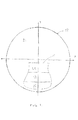
図6は本発明のレンズに使用する不連続的な光学的要素の配置の好ましい実施形態を示している図である。遠距離視野領域61が不連続的な光学的要素62、光学的要素63および光学的要素64に沿って示されている。この実施形態においては、これらの光学的要素は、それらの中心がチャンネルおよび漸進的付加面の近域視野領域(これらの付加面および領域は図6に示されていない)の中心と一致するように位置合わせされている。この漸進的付加面は+1.25ジオプトリの付加屈折力を有しており、光学的要素は+0.75ジオプトリの付加屈折力を有している。図7に図6の実施形態の場合の屈折力プロファイルを示しているが、各点E1 、点E2 および点E3 は光学的要素62、光学的要素63および光学的要素64にそれぞれ相当する。図7において、屈折力における傾斜した増加は漸進的付加面の+1.25ジオプトリの付加屈折力によるものであり、各点E1 、点E2 および点E3 における段部は不連続的な光学的要素の曲率の変化によって生じている。
【0026】
図2、図3および図5は本発明の不連続的な光学的要素に有用な2種類の形状、すなわち、ステップ(段)式形状と円形のいわゆる「半球レンズ(bulls-eye)」形状を示している図である。これらの光学的要素は任意の既知の方法によって形成できる。適当な方法としては、研削、成形、キャスティング、ダイアモンド加工、フライス削り、研磨、熱成形またはこれらの組合せ等が挙げられるがこれらに限られない。さらに、光学的要素および漸進的付加面に加えて、レンズを眼鏡用途に適合するために構成された球面状および円環状(toric)の面のような別の表面部が使用できる。
【0027】
図2に示すような本発明の一実施形態において、光学的予備成形体20の凹面部21は+1.00ジオプトリの付加屈折力を有する漸進的付加面である。不連続的な非球面状の光学的要素22、光学的要素23および光学的要素24がこの凹面部21上に配置されており、他の光学的要素25および光学的要素26は凸面部27上に配置されている。この実施形態においては、最上の凸面状要素25の上側の境界部が最上の凹面状要素22の下側の境界部に位置合わせされているのが好ましい。図2において、光学的要素25および26の屈折力はそれぞれ+0.12ジオプトリおよび+0.24ジオプトリであり、他の光学的要素22、光学的要素23および光学的要素24の屈折力はそれぞれ+0.25ジオプトリ、+0.50ジオプトリおよび+0.75ジオプトリである。それゆえ、このレンズの総合の屈折力は(+0.24ジオプトリ)+(+0.75ジオプトリ)+(+1.00ジオプトリ)すなわち+1.99ジオプトリである。図2に示す実施形態において、円環状の面部28が上記の光学的予備成形体の凸面部27にキャスティングにより形成されて最終の所望のレンズが構成される。このような実施形態すなわち円環状レンズによる補正が凸状または凹状の面部のいずれかに備えられている態様においては、少なくとも1個の中間層29を形状が球面状であるレンズに備えるのが好ましい。
【0028】
図2において、光学的予備成形体における漸進的付加面の+1.00の付加屈折力のみがレンズの非点収差に寄与するので、このレンズにおける+1.99の付加屈折力は従来の+1.99の付加屈折力のPALにおいて生じる非点収差よりも小さくすることができる。従来技術の+1.99の付加屈折力を有するPALの場合には、レンズの非点収差は約+1.99ジオプトリのレンズ非点収差になる。それゆえ、図2の本発明によるレンズの非点収差は従来技術の漸進的付加型レンズに比して実質的に減少できる。さらに、レンズの中域から近域の視野領域に至るチャンネルの幅が増大できる。
【0029】
また、図2に示す実施形態において、光学的要素25および光学的要素26はレンズの凸状および凹状の面の間におけるレンズの層の中に埋め込まれている。このような実施形態においては、埋め込まれる要素を伴う面が円環状の面部29とは異なる屈折率であるのが好ましい。なお、これらの面の屈折率における差は約0.05乃至約0.50であり、好ましくは約0.1乃至約0.35である。
【0030】
好ましくは、図3に示すような大部分または全ての光学的要素31、光学的要素32および光学的要素33は図示のレンズ自体の凹面部でもある光学的予備成形体30の凹面部34上に配置されているか、最終的なレンズにおける凹面部34と凸面部35との間の層中に配置される。また、別の好ましい実施形態においては、これらの光学的要素は凸状のレンズ表面上、および当該レンズの凹面部と凸面部との間に配置されている。このような実施形態においては、光学的要素を含んでいる各面部または層が当該光学的要素を含まない面部や層とは異なる屈折率を有しているのが好ましい。このような配置が好ましい理由は、レンズ装着者を見る者に対してこれらの光学的要素の視認性が消去または最小化されるためにより良好な外観が得られるからである。
【0031】
図1において、本発明のレンズの別の実施形態を説明する。レンズ10のy軸はレンズ10をほぼ垂直方向に2等分する主中心線(子午線)を示している。一方、x軸はレンズ10におけるy=0の線を示している。また、遠距離視野領域11が示されている。付加屈折力+1.00で光学的要素12、光学的要素13および光学的要素14の下側に存在する漸進的付加面は図示していない。各光学的要素12と光学的要素13および光学的要素13と光学的要素14の間の屈折力の変化は0.25ジオプトリである。また、光学的要素12の屈折力は+0.25であり、要素13の屈折率は+0.50で、要素14の屈折率は+0.75ジオプトリである。従って、レンズ10の総合の付加屈折力は+1.75ジオプトリである。
【0032】
これらの光学的要素の最上の境界部はy=0の線すなわち0°−180°の線上またはこれよりも下に配置することができる。一般的に、これらの光学的要素は当該1個または複数の要素の上端部がy=0の線よりも約0mm乃至約18.5mm下で、当該1個または複数の要素の下端部がy=0の線よりも約5mm乃至約35mm下に配置される。図1は好ましい実施形態を示しており、光学的要素の最上の境界部がレンズにおけるy=0の線よりも約2mm下に配置されている。
【0033】
図4は図6のレンズの左下の4分円弧の表面トポグラフィの概略図である。水平線65すなわちy=0におけるレンズ60の中央部を通る切断線と、中央チャンネル66と、底部端部67とレンズの周辺端部68が示されている。図4から分かるように、不連続的な光学的要素62、光学的要素63および光学的要素64は周囲のレンズ領域および互いに実質的に異なる曲率を有している。これらの光学的要素はその窪み部がy軸に沿って連続的になるように構成されている。しかしながら、各光学的要素の異なる曲率のために、窪み部の不連続性がy軸から離れるにつれて二次関数的に増加し、水平方向の不連続部81、水平方向の不連続部82および水平方向の不連続部83として見ることができる。また、光学的要素62、光学的要素63および光学的要素64の左側には垂直方向の不連続部84のような垂直方向の不連続部が見られる。
【0034】
このような垂直方向の不連続部を減少するために、セグメント角度不連続部をレンズの中に導入する。すなわち、このセグメント角度不連続部の機能は部分84のような垂直方向の不連続部の大きさを減少することである。具体的には、遠距離視野領域61と要素62との間のセグメント角度不連続部による調整量は0.001ラジアンであり、要素62と要素63との間の調整量は0.0025ラジアンである。なお、要素63と要素64との間にはセグメント角度不連続部が存在していない。さらに、図4においてこれらのセグメント角度不連続部は見て分かるほど十分な大きさに示されていない。
【0035】
これら水平方向および垂直方向の不連続性は本発明において有用な不連続的な光学的要素の幅に実用的な限界値を設ける主要因となる。すなわち、屈折力において一定の不連続性がある場合に、水平方向の窪みによる不連続性はチャンネルから離れるにつれてx2 のように二次関数的に増加する。それゆえ、水平方向の窪みによる不連続性を所望の特定値以下に保つ必要がある場合には、上記の条件によって不連続的な光学的要素の幅に一定の限界を設けることが必要になる。さらに、垂直方向の不連続性ならびに当該不連続性により生じるプリズム現象に対しても同様に考慮する必要がある。
【0036】
図5は本発明のレンズのさらに別の実施形態を示している図である。光学的予備成形体40の凹面部41および凸面部42が示されている。凸面部42は1.50ジオプトリの付加屈折力を有する漸進的付加面である。光学的要素43乃至光学的要素46はそれぞれ+0.725ジオプトリ、+1.45ジオプトリ、+2.175ジオプトリおよび+2.90ジオプトリの屈折率を有している。各光学的要素は異なる2個の曲率半径の2個の球面の交差により形成される円形部分を有している。例えば、光学的要素43は基礎球面41(83.00mm)および半径92.4mmの球面の交差により形成されている。この光学的要素は凹面部41上において増加的な付加屈折力を与えるので、その曲率はより平坦、すなわち、当該光学的要素の曲率半径は基礎球面の曲率半径よりも大きい。同様に、光学的要素44は光学的要素43と同心の第2の円形部分であり、半径92.4mmの球面と曲率半径が105.6mmに等しい第3の球面との交差により形成される部分である。それゆえ、図5の不連続的な光学的要素は同心状の縮小した一連の球面部分の形態に配列されている。光学的予備成形体40の屈折率は1.586である。光学的要素43乃至光学的要素46はこの光学的予備成形体40の中に形成されている。さらに、層が光学的予備成形体40の凹面部41上にキャスティングによって形成されている。このキャスティング層の屈折率は光学的予備成形体40の屈折率と0.1単位だけ異なる。
【0037】
このような場合において、各光学的要素の屈折力は以下のように影響を受ける。すなわち、各光学的構成要素の屈折力は、任意の要素の屈折力をxで割ることによって算出でき、この場合のxは次式により現せる。
x=(n1 −1.00)/(n1 −n2 )
この式において、n1 は光学的予備成形体の屈折率であり、n2 はキャスティング層の屈折率である。従って、図5の場合には、
x=(1.586−1.00)/0.1=5.86となる。
例えば、光学的要素43は+0.725ジオプトリの屈折力を有しているので、0.725を5.86で割ることにより当該要素43の付加屈折力が+0.125ジオプトリとなる。この結果、光学的要素全体の付加屈折力は+0.50ジオプトリとなり、図5のレンズの総合の付加屈折力は+2.00ジオプトリとなる。
【0038】
図8は連続的な光学的要素を用いた本発明のレンズの一実施形態を示している図である。光学的予備成形体70は遠距離視野領域74、近域視野領域75および中域視野領域77を有する漸進的付加型凸面部71を備えている。この漸進的付加面71の付加屈折力は+1.60ジオプトリである。さらに、凹面部72は球面領域76および近域視野領域75に直交して配置された連続的な光学的要素73を備えている。この光学的要素73の付加屈折力は+0.40ジオプトリである。凸面部71は領域74において4.50ジオプトリの曲率を有しており、領域75においては6.10ジオプトリの曲率を有している。また、凹面部72は領域76において4.50ジオプトリの曲率であり、領域73においては4.10ジオプトリの曲率を有している。従って、結果として得られるレンズは+2.00ジオプトリの付加屈折力を有しており、この値は漸進的付加面の付加屈折力と連続的な光学的要素73の付加屈折力との合計値である。
【0039】
図9(a)および図9(b)は連続的な光学的要素を用いる本発明のレンズのさらに別の実施形態を示している図である。すなわち、レンズ80は屈折力が連続的に増加する遠距離視野領域85、近域視野領域86および中域視野領域88を有する漸進的付加面から成る凸面部82を有する光学的予備成形体81により構成されている。一方、凹面部83は遠距離視野領域である球面領域87を有している。さらに、連続的な光学的要素84が近域視野領域86に直交して配置されている。この連続的な光学的要素84は予備成形体の球面領域87と端部89との間で屈折力が漸進的に変化している。凸面部82は領域85において4.50ジオプトリの曲率を有しており、領域86において6.00ジオプトリの曲率を有している。また、凹面部83は領域86において4.50ジオプトリの曲率を有しており、要素84の中心点である点Aにおいて4.00ジオプトリの曲率を有している。この結果として得られるレンズは2.00ジオプトリの付加屈折力を備える。図9(b)に光学的要素84の屈折力プロファイルを示す。図9(b)において、実線は要素84の屈折力プロファイルを示しており、破線は不連続的な同心状の光学的要素のプロファイルを比較用に示している。
【0040】
図9(b)は光学的要素84の混合された同心円状の屈折力プロファイルを示している図である。このプロファイルは非球面状または混合した半径の曲面により互いに円滑に接続している一定の屈折力の領域を有している。このような混合によって連続的な窪みの曲率半径および各要素における連続的な屈折力プロファイルが得られる。
【0041】
図10(a)および図10(b)は連続的な要素を用いる本発明のレンズのさらに別の実施形態を示している図である。レンズ90は凸面部92を有する光学的予備成形体91により構成されている。この凸面部92は漸進的に屈曲率が増加している遠距離視野領域95、近域視野領域96および中域視野領域97を備えている。一方、凹面部93は遠距離視野領域98および近域視野領域96に直交する連続的な光学的要素94を含んでいる。この連続的な光学的要素94は遠距離視野領域98からその端部99の間で漸進的に変化する屈折力を有している。
【0042】
凸面部92は遠距離視野領域95において4.50ジオプトリの曲率であり、近域視野領域96において5.50ジオプトリの曲率を有している。また、凹面部93は遠距離視野領域98において4.50ジオプトリの曲率であり、光学的要素94の中心点Bにおいて3.50ジオプトリの曲率を有している。それゆえ、レンズ90は2.00ジオプトリの付加屈折力を有している。図10(b)はレンズ90の屈折率プロファイルを実線で示しており、不連続的な同心状の光学的要素の場合の屈折率プロファイルを比較用として点線で示している図である。
【0043】
図10(b)は連続的な光学的要素において非球面状の屈折力プロファイルを示している図である。このプロファイルにおいては、曲率半径が一定である場所がなくて、光学的要素の中心からその端部にかけて滑らかに変化している。従って、図10(a)に示す実施形態の場合は、図10(b)から分かるように、屈折力プロファイルが各同心状領域の中心点における基準の不連続的な同心状の光学的要素のプロファイルと交わっている。
【0044】
本発明の具体的な実施態様は以下の通りである。
(1)前記レンズが眼鏡用レンズである請求項1に記載のレンズ。
(2)さらに、第3の付加屈折力(ジオプトリ単位)を有する2個以上の不連続的な光学的要素から成り、当該2個以上の不連続的な光学的要素の少なくとも1個が前記近域視野領域に重なるように配置されており、レンズの付加屈折力が前記第1の付加屈折力および第2の付加屈折力および第3の付加屈折力の合計である請求項1に記載のレンズ。
(3)前記光学的予備成形体の漸進的付加面における近域視野領域がさらに中心を有しており、前記1個以上の連続的な光学的要素がさらに中心を有しており、当該1個以上の連続的な光学的要素の少なくとも1個の中心が前記近域視野領域の中心と一致するように配置されている請求項1に記載のレンズ。
(4)前記1個以上の連続的な光学的要素が前記漸進的付加面と反対側の面の上か、漸進的付加面と当該漸進的付加面と反対側の面との間における層の中か、あるいは、これらの組合せで配置されている請求項1に記載のレンズ。
(5)前記1個以上の連続的な光学的要素が前記漸進的付加面と反対側の面の上か、漸進的付加面と当該漸進的付加面と反対側の面との間における層の中か、あるいは、これらの組合せで配置されており、前記2個以上の不連続的な光学的要素が漸進的付加面の上か、漸進的付加面と反対側の面の上か、漸進的付加面と当該漸進的付加面と反対側の面との間における層の中か、あるいは、これらの組合せで配置されている実施態様(2)に記載のレンズ。
【0045】
(6)前記光学的予備成形体の付加屈折力が約+0.01ジオプトリ乃至約+3.00ジオプトリであり、前記1個以上の連続的な光学的要素の付加屈折力が約+0.01ジオプトリ乃至約+3.00ジオプトリである請求項1に記載のレンズ。
(7)前記光学的予備成形体の付加屈折力、前記1個以上の連続的な光学的要素の付加屈折力、および前記2個以上の不連続的な光学的要素の付加屈折力が、それぞれ独立して、約+0.01ジオプトリ乃至約+3.00ジオプトリである実施態様(2)に記載のレンズ。
(8)さらに、中心と約+0.25ジオプトリ乃至約+2.00ジオプトリの第3の付加屈折力を有する2個以上の不連続的な光学的要素から成り、当該2個以上の不連続的な光学的要素の少なくとも1個がその中心と前記近域視野領域の中心が重なるように配置されており、レンズの付加屈折力が前記第1の付加屈折力および第2の付加屈折力および第3の付加屈折力の合計である請求項2に記載のレンズ。
(9)前記2個以上の不連続的な光学的要素が漸進的付加面の上か、漸進的付加面と反対側の面の上か、漸進的付加面と当該漸進的付加面と反対側の面との間における層の中か、あるいは、これらの組合せで配置されている実施態様(8)に記載のレンズ。
(10)前記レンズが眼鏡用レンズである請求項3に記載のレンズ。
【0046】
(11)さらに、第3の付加屈折力(ジオプトリ単位)を有する1個以上の連続的な光学的要素から成り、当該1個以上の連続的な光学的要素の少なくとも1個が前記近域視野領域に重なるように配置されており、レンズの付加屈折力が前記第1の付加屈折力および第2の付加屈折力および第3の付加屈折力の合計である請求項3に記載のレンズ。
(12)前記漸進的付加面の近域視野領域がさらに中心を有しており、前記2個以上の不連続的な光学的要素がさらに中心を有しており、当該2個以上の不連続的な光学的要素の少なくとも1個がその中心と前記近域視野領域の中心が一致するように配置されている請求項3に記載のレンズ。
(13)前記2個以上の不連続的な光学的要素が前記漸進的付加面の上か、漸進的付加面と反対側の面の上か、漸進的付加面と当該漸進的付加面と反対側の面との間における層の中か、あるいは、これらの組合せで配置されている請求項3に記載のレンズ。
(14)前記1個以上の連続的な光学的要素が前記漸進的付加面と反対側の面の上か、漸進的付加面と当該漸進的付加面と反対側の面との間における層の中か、あるいは、これらの組合せで配置されており、前記2個以上の不連続的な光学的要素が漸進的付加面の上か、漸進的付加面と反対側の面の上か、漸進的付加面と当該漸進的付加面と反対側の面との間における層の中か、あるいは、これらの組合せで配置されている実施態様(11)に記載のレンズ。
(15)前記光学的予備成形体の付加屈折力および前記2個以上の不連続的な光学的要素の付加屈折力が、それぞれ独立して、約+0.01ジオプトリ乃至約+3.00ジオプトリである請求項3に記載のレンズ。
【0047】
(16)前記光学的予備成形体の付加屈折力が約+0.01ジオプトリ乃至約+3.00ジオプトリであり、前記1個以上の連続的な光学的要素の付加屈折力および前記2個以上の不連続的な光学的要素の付加屈折力が、それぞれ独立して、約+0.01ジオプトリ乃至約+3.00ジオプトリである実施態様(11)に記載のレンズ。
(17)さらに、約+0.25ジオプトリ乃至約+2.00ジオプトリの第3の付加屈折力を有する1個以上の連続的な光学的要素から成り、レンズの付加屈折力が前記第1の付加屈折力および第2の付加屈折力および第3の付加屈折力の合計である請求項4に記載のレンズ。
(18)前記1個以上の連続的な光学的要素が前記漸進的付加面と反対側の面の上か、漸進的付加面と当該漸進的付加面と反対側の面との間における層の中か、あるいは、これらの組合せで配置されている請求項4に記載のレンズ。
【0048】
【発明の効果】
以上説明したように、本発明によれば、従来技術のPAL(漸進的付加型レンズ)に固有の問題の幾つかを解消できるPALが提供できる。
【図面の簡単な説明】
【図1】本発明のレンズの実施形態の正面図である。
【図2】本発明のレンズの実施形態の分解側面図である。
【図3】本発明のレンズの実施形態の分解側面図である。
【図4】図6のレンズの表面における一部分を示す概略図である。
【図5】本発明のレンズの実施形態の後面図および側面図である。
【図6】本発明のレンズの実施形態の正面図である。
【図7】図6のレンズの屈折力を示すグラフ図である。
【図8】本発明のレンズの実施形態の側面図である。
【図9】(a)は本発明のレンズの実施形態の側面図であり、(b)は(a)のレンズの連続的要素の屈折力を示すグラフ図である。
【図10】(a)は本発明のレンズの実施形態の側面図であり、(b)は(a)のレンズの連続的要素の屈折力を示すグラフ図である。
【符号の説明】
10 レンズ
11 遠域視野領域
12,13,14 光学的要素[0001]
BACKGROUND OF THE INVENTION
The present invention relates to a multifocal spectacle lens. In particular, the present invention provides a progressive addition lens with reduced unwanted lens astigmatism. At the same time, the channel width over the mid-range and near-field fields is increased compared to conventional progressive addition lenses.
[0002]
[Prior art]
The use of spectacle lenses for correction of refractive errors (myopia, hyperopia, astigmatism, etc.) is well known. For example, multifocal lenses such as progressive addition lenses (hereinafter referred to as PAL) are used to treat presbyopia or presbyopia. The surface of the PAL is stepped through the far-field, mid-field, and near-field regions where the refractive power from the far region to the near focal region or the upper surface to the lower surface of the lens increases continuously and gradually in the vertical direction. In preparation. PAL has gained popularity with the wearer because there is no visual boundary between the regions of different powers found in lenses such as other multifocal types, such as bifocal or trifocal.
[0003]
However, an inherent disadvantage in PAL is astigmatism in unwanted lenses or astigmatism induced or caused by one or more lens surfaces. In general, the astigmatism of an undesired lens roughly corresponds to the near field. For example, a PAL having a near field power of 2.00 diopters has an undesirable lens astigmatism of about 2.00 diopters. In addition, in the lens area free of unwanted astigmatism, the field of view of the wearer from the far field to the near field or vice versa is very narrow.
[0004]
[Problems to be solved by the invention]
To eliminate these disadvantages, any number of lens configurations have been attempted. However, current gradual lens configurations in the art only slightly reduce unwanted lens astigmatism, and large areas around the lens are still unusable due to unwanted astigmatism. Therefore, there is a need for a PAL that can overcome some of the problems inherent in prior art PALs.
[0005]
[Means for Solving the Problems]
The present invention provides a progressive addition lens and a method of constructing and manufacturing the lens, in which unwanted lens astigmatism associated with any near field power is substantially less than in the prior art. Can be reduced. In addition, the minimum channel width of the lens of the present invention is increased compared to the prior art PAL.
[0006]
For the purposes of the present invention, “channel” means an optical region free of unwanted astigmatism greater than about 0.75 diopters, which region is in the central umbilical meridian (in view). In this case, the spectacle wearer scans the field of view from the far object to the near object or vice versa. “Lens (lens)” means a lens used in the eye including, but not limited to, a spectacle lens, a contact lens, and an intraocular lens. Preferably, the lens of the present invention is a spectacle lens.
[0007]
DETAILED DESCRIPTION OF THE INVENTION
The discovery of the present invention is that undesired lens astigmatism can be reduced by combining one or more optical elements with a progressive addition surface. These optical elements provide additional power (diopter units) to the final lens so that the astigmatism of the lens does not increase to the level found in conventional PAL. Further, the lens of the present invention provides a minimum channel width that is wider than the minimum channel width of current or conventional progressive addition lenses.
[0008]
In one example embodiment, the lens of the present invention comprises: a) a progressive addition surface having a near field region and a first additional refractive power (diopter unit), or mainly constituted by these, or only And b) one or more continuous optical elements having a second additional refractive power (diopter unit), or mainly constituted by these, These are constituted only by them, and are arranged so that at least one of the one or more optical elements overlaps the near field region, and the additional refractive power of the lens is the first additional refractive power. The total value of the power and the second additional refractive power. “Optical preform” in this case means any multifocal lens such as a progressive addition lens or an optical element. Also, for purposes of the present invention, a “progressive addition surface” is a region of the far field and near field, and an increased refractive power connecting these far and near field regions. Means a continuous, aspherical surface having the following areas:
[0009]
In another embodiment, the lens of the present invention consists of, or consists essentially of, a) a progressive addition surface having a near field region and a first additional refractive power (diopter unit). Or b) two or more discontinuous optical elements having a second additional refractive power (diopter unit), or mainly constituted by these. , And are arranged so that at least one of the two or more discontinuous optical elements overlaps the near-field region, and the additional refractive power of the lens is The sum of the first additional refractive power and the second additional refractive power is obtained.
[0010]
The progressive addition surface can be disposed on the convex or concave surface of the optical preform, or it is provided in layers between the outer convex or outer concave surface of the lens. Also good. The curvature of the progressive addition surface changes in a direction increasing from the far field to the near field. Further, the additional refractive power of the progressive addition surface is the amount of change in refractive power between the far field and the near field. The additional refractive power of the progressive addition surface used in the present invention is selected to be a value smaller than that required to correct the near field of view of the lens wearer. That is, the incremental power of the progressive addition surface can range from about +0.01 diopters to about +3.00 diopters, preferably from about +1.00 diopters to about +2.75 diopters.
[0011]
In addition, the progressive addition surface add power is the largest lens undesired astigmatism, minimum desired channel width, and overall lens appearance with any near field power. Is selected based on the total addition power required for the finishing lens in consideration of maintenance of safety. This “cosmetically appealing” means that the visibility of each optical element in the lens is eliminated or minimized for the person viewing the wearer of the lens.
[0012]
To obtain the total additional power required to correct the wearer's presbyopia in the lens of the present invention, additional power is added to the additional power provided by the progressive addition surface. At least one optical element is used. These optical elements can be continuous, discontinuous, or a combination thereof. This “discontinuous” means that there is a discontinuous change in the sag value between the progressive addition surface and the optical element and between the optical element and the optical element. And / or there is a change in the slope along the x-axis and y-axis relative to the z-axis between the progressive addition surface and the optical element and between the optical element and the optical element, or both Means. Also, “continuous” means that the degree of depression and slope of each element is almost continuous or discontinuity of about 0.00 to about 0.100 diopters, preferably about 0. It is meant to include a change equal to or less than 0.000 diopters to about 0.05 diopters.
[0013]
Those skilled in the art will appreciate that the optical elements useful in the present invention described above can be spherical, aspherical, or combinations thereof, and any shape conventionally used. Further, it can be seen that lenses having continuous or discontinuous surfaces are formed by using either or both continuous or discontinuous optical elements.
[0014]
In embodiments that use discontinuous optical elements, two or more optical elements may be used, and these optical elements may be located on the same plane as the progressive addition surface. May be located on the opposite side of the face, or in a layer between the progressive addition face and the opposite face, and in a combination of these. You can also. Also, in embodiments that use continuous optical elements, one or more optical elements may be used, and these optical elements may be located on the opposite side of the progressive addition surface. It may be arranged in a layer between the additional surface and the opposite surface, or in a combination thereof.
[0015]
These optical elements are generally arranged such that the near field region of the progressive addition surface is overlapped by at least one of the optical elements. Preferably, the optical element is arranged so that the center of the at least one optical element coincides with the center of the near field region of the progressive addition surface. More preferably, the optical element is arranged so that the center of at least one optical element coincides with the center of the near field region and the center of the channel. For the purposes of the present invention, one optical element is superimposed on the near field region or coincident with the center of the near field region or channel without being placed on the same plane as the progressive addition surface. Is possible.
[0016]
In embodiments that use discontinuous optical elements, the sag discontinuities become visible in the lens as lines, making the appearance unfavorable if the degree exceeds a certain limit. Become. Further, in the discontinuous portion of the slope, image doubling or disappearance occurs, and if the degree exceeds a certain limit, it becomes functionally unacceptable. In addition, the surface having the discontinuity of the depression can be coated with one or more coating materials in order to minimize the visibility of the line. As a coating material suitable for such an application, any coating material used for a lens can be used, and it has a refractive index within 20% of the geometric average of the coated lens surface and the refractive index of air.
[0017]
In the present invention, it has been found that the maximum range of indentations that can be made inconspicuous by the coating material is from about 0 microns to about 10 microns. Therefore, the range of depression discontinuities in the discontinuous optical elements used in the present invention is from about 0 microns to about 10 microns, preferably from about 0 microns to about 5 microns. The limit value for this indentation discontinuity corresponds to an increase in refractive power of about 0 diopters to about 0.125 diopters, preferably about 0 diopters to about 0.065 diopters in a 12 mm long element. For slope discontinuities, the maximum range of slope discontinuities may correspond to an increase in refractive power of about 0 diopters to about 0.25 diopters, preferably about 0 diopters to about 0.125 diopters. I know it.
[0018]
In view of these limits, it has been found preferable to obtain the desired additional power increase using at least two, preferably about 2 to 5, discrete optical elements. . As for the spacing between elements, the slope discontinuities cause the image to overlap and produce unwanted astigmatism, the magnitude of which is between the slope discontinuity magnitude and the discontinuous optical elements. Proportional to interval. That is, the smaller the distance between the elements, the larger the number of images generated by scanning with the pupil of the optical element.
[0019]
For example, if the discontinuous optical elements are 2 mm apart, a 5 mm diameter pupil will produce up to 4 images simultaneously. On the other hand, additional astigmatism due to image blurring can be minimized by keeping the number of images generated by the 5 mm diameter pupil up to two. Therefore, it is preferred that the discontinuous optical elements be spaced apart from each other by about 3 mm to about 18 mm, more preferably from about 5 mm to about 15 mm. By using such an interval, the astigmatism accompanied by the discontinuity of the slope of 0.08 diopter is reduced to 0.05 diopter or less, and the image superposition is below a level that is visible to the wearer of the optical element. become. Note that the spacing between these optical elements may be further reduced if higher levels of image blur and astigmatism are acceptable.
[0020]
Each discontinuous optical element may have the same refractive power, but preferably has a different refractive power. In embodiments having discontinuous optical elements, preferably two or more optical elements are used, and the refractive power is changed from the first element to the second element, to the third element, etc. It is preferable to change as it moves. However, it is preferable that the change in the refractive power between the elements is such that the wearer has a minimum or no perception of the change in the refractive power. In general, the change in refractive power during movement between elements is less than or equal to about 1.50 diopters, preferably less than or equal to about 0.50 diopters, more preferably less than or equal to about 0.37 diopters, and most preferably zero. .25 diopters or less.
[0021]
The refractive power of each optical element is determined by the radius of curvature of the element, and the refractive power increases as the curvature of the element decreases. Thus, each optical element is about +0.01 diopters to about +3.00 diopters, preferably about +0.01 diopters to about +2.00 diopters, more preferably about +0.01 diopters to about +0.50 diopters, Most preferably in the range of about +0.03 diopters to about +0.25 diopters, the optical preform is provided with progressive addition power. The additional refractive power of the optical element is the incremental additional power provided by the element, and this refractive power can be easily determined by a person skilled in the art.
[0022]
For example, in FIG. 1, the change in optical power between optical elements is 0.25 diopters, and the refractive power of each element is +0.25 diopters for the top element 12 and for the second element 13. +0.50 diopters, and in the case of the third element 14 +0.75 diopters. Therefore, the added power of these optical elements is +0.75 diopters. In the case of another example shown in FIG. 2, the refractive powers of the
[0023]
In embodiments of the lens of the present invention where a change in refractive power between the optical elements causes a recess discontinuity in the channel, the recess discontinuity adjusts the relative height of each optical element. Is set to about 0 micron in the center of the channel. Also, the overall recess discontinuity along the vertical line of these optical elements can be reduced by providing a very small angle, i.e., a segment angle discontinuity, at the horizontal segment boundary of each element.
[0024]
The position and shape of the optical element can be determined by known techniques. For example, the position and shape can be evaluated, configured and identified using ray tracing and measurement test results for the lens. In addition, the surface irregularities due to each element can be optimized by known processing in accordance with the best imaging characteristics. For example, such optimization can be performed by commercially available optical design software.
[0025]
FIG. 6 shows a preferred embodiment of the discontinuous optical element arrangement used in the lens of the present invention. A far field region 61 is shown along the discontinuous optical element 62, optical element 63 and optical element 64. In this embodiment, these optical elements are such that their centers coincide with the centers of the near field region of the channel and the progressive addition surface (these addition surfaces and regions are not shown in FIG. 6). Are aligned. This progressive addition surface has an additional refractive power of +1.25 diopters and the optical element has an additional refractive power of +0.75 diopters. FIG. 7 shows the refractive power profile in the case of the embodiment of FIG. 1 , Point E 2 And point E Three Corresponds to the optical element 62, the optical element 63 and the optical element 64, respectively. In FIG. 7, the ramped increase in refractive power is due to the additional refractive power of +1.25 diopters of the progressive addition surface, and each point E 1 , Point E 2 And point E Three The step in is caused by a change in the curvature of the discontinuous optical element.
[0026]
2, 3 and 5 show two types of shapes useful for the discontinuous optical element of the present invention: a stepped shape and a circular so-called “bulls-eye” shape. FIG. These optical elements can be formed by any known method. Suitable methods include, but are not limited to, grinding, molding, casting, diamond processing, milling, polishing, thermoforming, or combinations thereof. Further, in addition to the optical elements and progressive addition surfaces, other surface portions can be used such as spherical and toric surfaces configured to adapt the lens to spectacle applications.
[0027]
In one embodiment of the present invention as shown in FIG. 2, the concave surface portion 21 of the optical preform 20 is a progressive addition surface having an addition power of +1.00 diopters. Discontinuous aspherical
[0028]
In FIG. 2, only the additional refractive power of +1.00 on the progressive addition surface of the optical preform contributes to the astigmatism of the lens, so that the additional refractive power of +1.99 in this lens is the conventional +1.99. The astigmatism generated in the PAL having the additional refractive power of 1 can be made smaller. In the case of the prior art PAL having an additional refractive power of +1.99, the lens astigmatism is approximately +1.99 diopter lens astigmatism. Therefore, the astigmatism of the lens according to the invention of FIG. 2 can be substantially reduced compared to the progressive addition lenses of the prior art. Furthermore, the channel width from the middle region of the lens to the near field region can be increased.
[0029]
Also, in the embodiment shown in FIG. 2, optical element 25 and optical element 26 are embedded in the lens layer between the convex and concave surfaces of the lens. In such an embodiment, it is preferred that the surface with the embedded element has a different refractive index than the
[0030]
Preferably, most or all of the
[0031]
In FIG. 1, another embodiment of the lens of the present invention will be described. The y-axis of the
[0032]
The uppermost boundary of these optical elements can be placed on or below the y = 0 line, ie the 0 ° -180 ° line. Generally, these optical elements are such that the upper end of the one or more elements is about 0 mm to about 18.5 mm below the line y = 0 and the lower end of the one or more elements is y = 0 to about 35 mm to about 35 mm below the line of = 0. FIG. 1 shows a preferred embodiment in which the uppermost boundary of the optical element is located about 2 mm below the y = 0 line in the lens.
[0033]
FIG. 4 is a schematic diagram of the surface topography of the lower left quadrant arc of the lens of FIG. A horizontal line 65, i.e., a cutting line through the center of lens 60 at y = 0, a center channel 66, a bottom end 67 and a peripheral edge 68 of the lens is shown. As can be seen from FIG. 4, the discontinuous optical element 62, the optical element 63 and the optical element 64 have a surrounding lens region and a curvature that is substantially different from each other. These optical elements are configured such that the depressions are continuous along the y-axis. However, due to the different curvature of each optical element, the indentation discontinuity increases quadratically with distance from the y-axis, such as
[0034]
In order to reduce such vertical discontinuities, segment angle discontinuities are introduced into the lens. That is, the function of this segment angle discontinuity is to reduce the size of the vertical discontinuity such as
[0035]
These horizontal and vertical discontinuities are a major factor in placing practical limits on the width of the discontinuous optical elements useful in the present invention. That is, if there is a constant discontinuity in refractive power, the discontinuity due to the horizontal depression will be x as it moves away from the channel. 2 It increases like a quadratic function. Therefore, when it is necessary to keep the discontinuity due to the horizontal depression below a desired specific value, the above condition makes it necessary to set a certain limit on the width of the discontinuous optical element. . Furthermore, it is necessary to similarly consider the vertical discontinuity and the prism phenomenon caused by the discontinuity.
[0036]
FIG. 5 is a view showing still another embodiment of the lens of the present invention. A
[0037]
In such a case, the refractive power of each optical element is affected as follows. That is, the refractive power of each optical component can be calculated by dividing the refractive power of an arbitrary element by x. In this case, x can be expressed by the following equation.
x = (n 1 -1.00) / (n 1 -N 2 )
In this equation, n 1 Is the refractive index of the optical preform, n 2 Is the refractive index of the casting layer. Therefore, in the case of FIG.
x = (1.586-1.00) /0.1=5.86.
For example,
[0038]
FIG. 8 shows one embodiment of the lens of the present invention using continuous optical elements. The
[0039]
FIGS. 9 (a) and 9 (b) illustrate yet another embodiment of the lens of the present invention that uses continuous optical elements. That is, the lens 80 is formed by an
[0040]
FIG. 9B is a diagram showing a concentric refractive power profile in which
[0041]
FIGS. 10 (a) and 10 (b) show yet another embodiment of the lens of the present invention using continuous elements. The
[0042]
The
[0043]
FIG. 10B is a diagram showing an aspherical refractive power profile in a continuous optical element. In this profile, there is no place where the radius of curvature is constant, and it changes smoothly from the center of the optical element to its end. Accordingly, in the case of the embodiment shown in FIG. 10 (a), as can be seen from FIG. 10 (b), the refractive power profile of the reference discontinuous concentric optical element at the center point of each concentric region. Interact with profile.
[0044]
Specific embodiments of the present invention are as follows.
(1) The lens according to claim 1, wherein the lens is a lens for spectacles.
(2) Further, it is composed of two or more discontinuous optical elements having a third additional refractive power (diopter unit), and at least one of the two or more discontinuous optical elements is in the vicinity. 2. The lens according to claim 1, wherein the lens is disposed so as to overlap with a region visual field region, and an additional refractive power of the lens is a sum of the first additional refractive power, the second additional refractive power, and the third additional refractive power. .
(3) The near field region in the progressive addition surface of the optical preform further has a center, and the one or more continuous optical elements further have a center, The lens according to claim 1, wherein at least one center of one or more continuous optical elements is arranged to coincide with a center of the near field region.
(4) the one or more continuous optical elements are on a surface opposite the progressive addition surface or between the progressive addition surface and the surface opposite the progressive addition surface; The lens according to claim 1, wherein the lens is arranged in the middle or a combination thereof.
(5) the one or more continuous optical elements are on a surface opposite the progressive addition surface, or between the progressive addition surface and the surface opposite the progressive addition surface; Arranged in or in combination, wherein the two or more discrete optical elements are on a progressive addition surface, on a surface opposite to the progressive addition surface, or progressive The lens according to embodiment (2), arranged in a layer between the additional surface and the surface opposite to the progressive additional surface, or a combination thereof.
[0045]
(6) the optical preform has an added power of about +0.01 diopters to about +3.00 diopters, and the one or more continuous optical elements have an added power of about +0.01 diopters to The lens of claim 1 which is about +3.00 diopters.
(7) The additional refractive power of the optical preform, the additional refractive power of the one or more continuous optical elements, and the additional refractive power of the two or more discontinuous optical elements are respectively The lens of embodiment (2), which is independently from about +0.01 diopters to about +3.00 diopters.
(8) further comprising two or more discontinuous optical elements having a center and a third additional refractive power of about +0.25 diopters to about +2.00 diopters, wherein the two or more discontinuous optical elements At least one of the optical elements is disposed so that the center thereof overlaps the center of the near-field region, and the additional refractive power of the lens is the first additional refractive power, the second additional refractive power, and the third additional power. The lens according to
(9) Whether the two or more discontinuous optical elements are on the progressive addition surface, on the surface opposite to the progressive addition surface, or on the side opposite to the progressive addition surface and the progressive addition surface The lens according to embodiment (8), which is arranged in a layer between the two surfaces or in combination thereof.
(10) The lens according to claim 3, wherein the lens is a spectacle lens.
[0046]
(11) Furthermore, it comprises one or more continuous optical elements having a third additional refractive power (diopter unit), and at least one of the one or more continuous optical elements is the near field field 4. The lens according to claim 3, wherein the lens is disposed so as to overlap the region, and an additional refractive power of the lens is a sum of the first additional refractive power, the second additional refractive power, and the third additional refractive power.
(12) The near-field region of the progressive addition surface further has a center, and the two or more discontinuous optical elements further have a center, and the two or more discontinuities 4. A lens according to claim 3, wherein at least one of the optical elements is arranged such that its center coincides with the center of the near field region.
(13) Whether the two or more discontinuous optical elements are on the progressive addition surface, on a surface opposite to the progressive addition surface, or on the progressive addition surface and opposite to the progressive addition surface 4. A lens according to claim 3, arranged in a layer between the side surfaces or in a combination thereof.
(14) the one or more continuous optical elements are on a surface opposite to the progressive addition surface or between the progressive addition surface and the surface opposite the progressive addition surface; Arranged in or in combination, wherein the two or more discrete optical elements are on a progressive addition surface, on a surface opposite to the progressive addition surface, or progressive The lens according to embodiment (11), arranged in a layer between the additional surface and the surface opposite to the progressive additional surface, or a combination thereof.
(15) The additional refractive power of the optical preform and the additional refractive power of the two or more discontinuous optical elements are each independently about +0.01 diopter to about +3.00 diopter. The lens according to claim 3.
[0047]
(16) the optical preform has an additional refractive power of about +0.01 diopters to about +3.00 diopters, the additional refractive power of the one or more continuous optical elements and the two or more non-reflecting powers; The lens of embodiment (11), wherein the additional optical powers of the continuous optical elements are each independently about +0.01 diopters to about +3.00 diopters.
(17) and further comprising one or more continuous optical elements having a third additional refractive power of about +0.25 diopters to about +2.00 diopters, wherein the additional refractive power of the lens is the first additional refractive power. The lens according to claim 4, which is the sum of the power, the second additional power, and the third additional power.
(18) the one or more continuous optical elements are on a surface opposite the progressive addition surface or between the progressive addition surface and the surface opposite the progressive addition surface; The lens according to claim 4, which is arranged in the middle or a combination thereof.
[0048]
【The invention's effect】
As described above, according to the present invention, it is possible to provide a PAL that can solve some of the problems inherent in the prior art PAL (gradual addition type lens).
[Brief description of the drawings]
FIG. 1 is a front view of an embodiment of a lens of the present invention.
FIG. 2 is an exploded side view of an embodiment of the lens of the present invention.
FIG. 3 is an exploded side view of an embodiment of the lens of the present invention.
4 is a schematic view showing a part of the surface of the lens of FIG. 6;
FIGS. 5A and 5B are a rear view and a side view of an embodiment of the lens of the present invention. FIGS.
FIG. 6 is a front view of an embodiment of the lens of the present invention.
7 is a graph showing the refractive power of the lens shown in FIG. 6. FIG.
FIG. 8 is a side view of an embodiment of the lens of the present invention.
9A is a side view of an embodiment of the lens of the present invention, and FIG. 9B is a graph showing the refractive power of the continuous elements of the lens of FIG.
10A is a side view of an embodiment of the lens of the present invention, and FIG. 10B is a graph showing the refractive power of the continuous elements of the lens of FIG.
[Explanation of symbols]
10 Lens
11 Far field of view
12, 13, 14 Optical elements
Claims (5)
b)第2の付加屈折力(ジオプトリ単位)を有する2個以上の不連続的な光学的要素とから成り、不連続とは、漸進的付加面と光学的要素との間および光学的要素と光学的要素との間の窪みの程度(sagvalue)において不連続な変化が存在すること、および漸進的付加面と光学的要素との間および光学的要素と光学的要素との間でz軸に対するx軸およびy軸に沿う斜面において変化が存在することのいずれか、または両方を意味し、当該2個以上の不連続的な光学的要素の少なくとも1個が近域視野領域に重なるように配置されており、
当該レンズの付加屈折力が前記第1の付加屈折力および第2の付加屈折力の合計の値であることを特徴とする漸進的付加型レンズ。a) an optical preform including a far field region, a near field region, and a progressive addition surface having a first additional refractive power (diopter units);
b) consisting of two or more discontinuous optical elements having a second additional refractive power (diopter units), the discontinuity being between the progressive addition surface and the optical element and the optical element; There is a discontinuous change in the sagvalue between the optical elements and between the progressive addition surface and the optical element and between the optical element and the optical element with respect to the z-axis. Means that there is a change in the slope along the x-axis and the y-axis, or both, and is arranged so that at least one of the two or more discontinuous optical elements overlaps the near field region Has been
A progressive addition lens, wherein the additional refractive power of the lens is a sum of the first additional refractive power and the second additional refractive power.
Applications Claiming Priority (2)
| Application Number | Priority Date | Filing Date | Title |
|---|---|---|---|
| US09/146,888 US6086203A (en) | 1998-09-03 | 1998-09-03 | Progressive addition lenses |
| US146888 | 1999-08-02 |
Publications (2)
| Publication Number | Publication Date |
|---|---|
| JP2000105358A JP2000105358A (en) | 2000-04-11 |
| JP4531165B2 true JP4531165B2 (en) | 2010-08-25 |
Family
ID=22519433
Family Applications (1)
| Application Number | Title | Priority Date | Filing Date |
|---|---|---|---|
| JP24923399A Expired - Lifetime JP4531165B2 (en) | 1998-09-03 | 1999-09-02 | Progressive addition lens |
Country Status (15)
| Country | Link |
|---|---|
| US (1) | US6086203A (en) |
| EP (1) | EP0987578B1 (en) |
| JP (1) | JP4531165B2 (en) |
| KR (1) | KR100629407B1 (en) |
| CN (1) | CN100476512C (en) |
| AT (1) | ATE414929T1 (en) |
| AU (1) | AU767129B2 (en) |
| BR (1) | BR9904035A (en) |
| CA (1) | CA2281273C (en) |
| DE (1) | DE69939924D1 (en) |
| IL (1) | IL131639A (en) |
| MY (1) | MY118105A (en) |
| RU (1) | RU2229151C2 (en) |
| SG (1) | SG106566A1 (en) |
| TW (1) | TW486578B (en) |
Families Citing this family (59)
| Publication number | Priority date | Publication date | Assignee | Title |
|---|---|---|---|---|
| FR2793038B1 (en) * | 1999-04-29 | 2002-01-25 | Essilor Int | COMPOSITE OPHTHALMIC LENS AND METHOD FOR OBTAINING SUCH A LENS |
| AUPQ065599A0 (en) * | 1999-05-31 | 1999-06-24 | Sola International Holdings Ltd | Progressive lens |
| US6619799B1 (en) | 1999-07-02 | 2003-09-16 | E-Vision, Llc | Optical lens system with electro-active lens having alterably different focal lengths |
| US7988286B2 (en) | 1999-07-02 | 2011-08-02 | E-Vision Llc | Static progressive surface region in optical communication with a dynamic optic |
| US7775660B2 (en) | 1999-07-02 | 2010-08-17 | E-Vision Llc | Electro-active ophthalmic lens having an optical power blending region |
| WO2001025837A1 (en) * | 1999-10-01 | 2001-04-12 | Sola International Holdings Ltd | Progressive lens |
| AU772399B2 (en) * | 1999-10-01 | 2004-04-29 | Carl Zeiss Vision Australia Holdings Ltd | Progressive lens |
| US6390623B1 (en) * | 2000-03-29 | 2002-05-21 | Johnson & Johnson Vision Care, Inc. | Customized progressive addition lenses |
| US6505934B1 (en) * | 2001-04-27 | 2003-01-14 | Johnson & Johnson Vision Care, Inc. | Progressive addition lenses with prism power added to improve wearer comfort |
| JP3882764B2 (en) * | 2003-02-19 | 2007-02-21 | セイコーエプソン株式会社 | Progressive power lens |
| US9801709B2 (en) | 2004-11-02 | 2017-10-31 | E-Vision Smart Optics, Inc. | Electro-active intraocular lenses |
| US8778022B2 (en) | 2004-11-02 | 2014-07-15 | E-Vision Smart Optics Inc. | Electro-active intraocular lenses |
| US8915588B2 (en) | 2004-11-02 | 2014-12-23 | E-Vision Smart Optics, Inc. | Eyewear including a heads up display |
| GB0504448D0 (en) * | 2005-03-03 | 2005-04-06 | Spurgeon Peter J C | Optical apparatus and image processing |
| EP1894058A2 (en) * | 2005-06-20 | 2008-03-05 | ESSILOR INTERNATIONAL Compagnie Générale d'Optique | Method for providing dual surface progressive addition lens series |
| JP4973027B2 (en) * | 2005-08-22 | 2012-07-11 | セイコーエプソン株式会社 | Progressive power lens |
| US20080273166A1 (en) | 2007-05-04 | 2008-11-06 | William Kokonaski | Electronic eyeglass frame |
| EP2030073B1 (en) | 2006-06-23 | 2018-12-05 | Mitsui Chemicals, Inc. | Electronic adapter for electro-active spectacle lenses |
| AR064985A1 (en) | 2007-01-22 | 2009-05-06 | E Vision Llc | FLEXIBLE ELECTROACTIVE LENS |
| US8215770B2 (en) | 2007-02-23 | 2012-07-10 | E-A Ophthalmics | Ophthalmic dynamic aperture |
| US20080273169A1 (en) * | 2007-03-29 | 2008-11-06 | Blum Ronald D | Multifocal Lens Having a Progressive Optical Power Region and a Discontinuity |
| US7883207B2 (en) | 2007-12-14 | 2011-02-08 | Pixeloptics, Inc. | Refractive-diffractive multifocal lens |
| JP2010520514A (en) | 2007-03-07 | 2010-06-10 | ピクセルオプティクス, インコーポレイテッド | Multifocal lens with progressive optical power region and discontinuity |
| TW200912425A (en) | 2007-03-29 | 2009-03-16 | Pixeloptics Inc | Multifocal lens having a progressive optical power region and a discontinuity |
| US11061252B2 (en) | 2007-05-04 | 2021-07-13 | E-Vision, Llc | Hinge for electronic spectacles |
| US10613355B2 (en) | 2007-05-04 | 2020-04-07 | E-Vision, Llc | Moisture-resistant eye wear |
| US8317321B2 (en) | 2007-07-03 | 2012-11-27 | Pixeloptics, Inc. | Multifocal lens with a diffractive optical power region |
| TWI487516B (en) | 2007-08-22 | 2015-06-11 | Novartis Ag | Presbyopic treatment system |
| US8974526B2 (en) | 2007-08-27 | 2015-03-10 | Amo Groningen B.V. | Multizonal lens with extended depth of focus |
| CA2704213A1 (en) * | 2007-10-30 | 2009-05-07 | Visionware Llc | Progressive reading and intermediate distance lens defined by employment of a zernike expansion |
| EP2365380A3 (en) | 2007-12-14 | 2012-05-02 | Pixeloptics Inc. | Multiple layer multifocal composite lens |
| US7926941B2 (en) * | 2007-12-14 | 2011-04-19 | Pixeloptics Inc. | Multiple layer multifocal composite lens |
| US7744215B2 (en) * | 2007-12-25 | 2010-06-29 | Pixeloptics, Inc. | Multiple layer multifocal composite lens |
| WO2009097255A1 (en) * | 2008-02-01 | 2009-08-06 | Pixeloptics Inc. | Multiple layer multifocal composite lens |
| WO2010071472A1 (en) * | 2008-12-15 | 2010-06-24 | Grechukhin Aleksandr Nikolayevich | Spectacles for increasing potency (sex spectacles) |
| KR20100114133A (en) | 2008-03-18 | 2010-10-22 | 픽셀옵틱스, 인크. | Advanced electro-active optic device |
| US8154804B2 (en) | 2008-03-25 | 2012-04-10 | E-Vision Smart Optics, Inc. | Electro-optic lenses for correction of higher order aberrations |
| US9022563B2 (en) * | 2009-02-12 | 2015-05-05 | Mitsui Chemicals, Inc. | Ophthalmic lenses with aspheric optical features |
| US8434864B2 (en) * | 2009-08-23 | 2013-05-07 | Pixeloptics, Inc. | Multifocal ophthalmic lens with discontinuities |
| US8573774B2 (en) * | 2009-10-14 | 2013-11-05 | PixelOptics | Opthalmic lens with regressive and non-regressive rotationally symmetric optical design elements |
| EP2646872A1 (en) | 2010-12-01 | 2013-10-09 | AMO Groningen B.V. | A multifocal lens having an optical add power progression, and a system and method of providing same |
| KR102060784B1 (en) | 2012-01-06 | 2019-12-30 | 에이치피오 애셋츠 엘엘씨 | Eyewear docking station and electronic module |
| TWI588560B (en) | 2012-04-05 | 2017-06-21 | 布萊恩荷登視覺協會 | Lenses, devices, methods and systems for refractive error |
| US9201250B2 (en) | 2012-10-17 | 2015-12-01 | Brien Holden Vision Institute | Lenses, devices, methods and systems for refractive error |
| TWI600418B (en) | 2012-10-17 | 2017-10-01 | 布萊恩荷登視覺協會 | Lenses, devices, methods and systems for refractive error |
| TWI626491B (en) * | 2012-12-10 | 2018-06-11 | 布萊恩荷登視覺協會 | Ophthalmic optical lens for vision correction having one or more areas of more positive power |
| EP2752703A1 (en) * | 2013-01-07 | 2014-07-09 | ESSILOR INTERNATIONAL (Compagnie Générale d'Optique) | Ophthalmic lens having at least a stable zone |
| US9726859B1 (en) * | 2014-03-16 | 2017-08-08 | Navitar Industries, Llc | Optical assembly for a wide field of view camera with low TV distortion |
| US9316820B1 (en) | 2014-03-16 | 2016-04-19 | Hyperion Development, LLC | Optical assembly for a wide field of view point action camera with low astigmatism |
| US10386604B1 (en) | 2014-03-16 | 2019-08-20 | Navitar Industries, Llc | Compact wide field of view digital camera with stray light impact suppression |
| US9995910B1 (en) | 2014-03-16 | 2018-06-12 | Navitar Industries, Llc | Optical assembly for a compact wide field of view digital camera with high MTF |
| US10545314B1 (en) | 2014-03-16 | 2020-01-28 | Navitar Industries, Llc | Optical assembly for a compact wide field of view digital camera with low lateral chromatic aberration |
| US9316808B1 (en) | 2014-03-16 | 2016-04-19 | Hyperion Development, LLC | Optical assembly for a wide field of view point action camera with a low sag aspheric lens element |
| US10139595B1 (en) | 2014-03-16 | 2018-11-27 | Navitar Industries, Llc | Optical assembly for a compact wide field of view digital camera with low first lens diameter to image diagonal ratio |
| US9494772B1 (en) | 2014-03-16 | 2016-11-15 | Hyperion Development, LLC | Optical assembly for a wide field of view point action camera with low field curvature |
| EP3413839A1 (en) | 2016-02-09 | 2018-12-19 | AMO Groningen B.V. | Progressive power intraocular lens, and methods of use and manufacture |
| EP3440508B1 (en) | 2016-04-12 | 2021-01-27 | E- Vision Smart Optics, Inc. | Electro-active lenses with raised resistive bridges |
| US10599006B2 (en) | 2016-04-12 | 2020-03-24 | E-Vision Smart Optics, Inc. | Electro-active lenses with raised resistive bridges |
| US11886046B2 (en) | 2019-12-30 | 2024-01-30 | Amo Groningen B.V. | Multi-region refractive lenses for vision treatment |
Citations (4)
| Publication number | Priority date | Publication date | Assignee | Title |
|---|---|---|---|---|
| JPS62500403A (en) * | 1984-08-17 | 1987-02-19 | オプティシェ ヴェルケジ−・ロ−デンストック | progressive eyeglass lenses |
| JPS63254415A (en) * | 1987-04-13 | 1988-10-21 | Seiko Epson Corp | Visual acuity remedying device using two progressive multifocus lenses |
| WO1989004987A1 (en) * | 1987-11-25 | 1989-06-01 | Hitoshi Okano | Multi-focal lens equipped with small progressive-focal lens |
| WO1993015432A1 (en) * | 1992-02-03 | 1993-08-05 | Seiko Epson Corporation | Variable focus visual power correction apparatus |
Family Cites Families (23)
| Publication number | Priority date | Publication date | Assignee | Title |
|---|---|---|---|---|
| US3711191A (en) * | 1971-09-16 | 1973-01-16 | L Tagnon | Aberration corrected ophthalmic progressive power lenses |
| US4055379A (en) * | 1973-08-16 | 1977-10-25 | American Optical Corporation | Multifocal lens |
| US4056311A (en) * | 1973-08-16 | 1977-11-01 | American Optical Corporation | Progressive power ophthalmic lens having a plurality of viewing zones with non-discontinuous variations therebetween |
| CA1012392A (en) * | 1973-08-16 | 1977-06-21 | American Optical Corporation | Progressive power ophthalmic lens |
| FR2425653A1 (en) * | 1978-05-12 | 1979-12-07 | Essilor Int | PROCESS FOR DEVELOPING A REFRACTION SURFACE OF AN OPHTHALMIC LENS WITH PROGRESSIVELY VARIABLE FOCAL POWER |
| FR2481813A1 (en) * | 1980-04-30 | 1981-11-06 | Essilor Int | PROGRESSIVE OPHTHALMIC LENS |
| FR2565358B1 (en) * | 1984-05-29 | 1988-05-06 | Bach Guy | ANASTIGMATIC OPTICAL SYSTEMS WITH ASPHERIC SURFACES |
| US5771089A (en) * | 1984-08-17 | 1998-06-23 | Optische Werke G. Rodenstock | Progressive spectacle lens |
| DE3433916C2 (en) * | 1984-09-15 | 1986-10-16 | Optische Werke G. Rodenstock, 8000 München | Lens for half glasses |
| GB8528460D0 (en) * | 1985-11-19 | 1985-12-24 | Sola Int Holdings | Multifocal lens |
| DE3716201C2 (en) * | 1987-05-14 | 2001-02-15 | Rodenstock Optik G | Progressive glasses |
| US4952048A (en) * | 1987-09-14 | 1990-08-28 | Opticorp, Inc. | Method of designing a non-progressive multifocal ophthalmic lens |
| US4859261A (en) * | 1988-05-11 | 1989-08-22 | Ace Ronald S | Method of making multi-focus ophthalmic lens |
| IT1230491B (en) * | 1988-07-21 | 1991-10-24 | Italtel Spa | TELEARM ALARM SERVICE USING THE PUBLIC TELEPHONE NETWORK. |
| US5305028A (en) * | 1990-04-24 | 1994-04-19 | Hitoshi Okano | Multifocal lens provided with progressive focal segment |
| JP2769931B2 (en) * | 1991-04-02 | 1998-06-25 | 利宜 白井 | Bifocal eyeglass lens |
| US5644374A (en) * | 1992-02-03 | 1997-07-01 | Seiko Epson Corporation | Variable focus type eyesight correcting apparatus |
| JP3619264B2 (en) * | 1994-08-22 | 2005-02-09 | ペンタックス株式会社 | Progressive multifocal lens and its mold |
| DE69638108D1 (en) * | 1995-11-24 | 2010-02-25 | Seiko Epson Corp | Multi-strength glass for spectacles and spectacle lenses |
| US6019470A (en) * | 1995-11-24 | 2000-02-01 | Seiko Epson Corporation | Progressive multifocal lens and manufacturing method of eyeglass lens and progressive multifocal lens |
| US5812237A (en) * | 1995-11-27 | 1998-09-22 | Roddy; Kenneth C. | Ophthalmic no-line progressive addition lenses |
| US5847803A (en) * | 1996-09-17 | 1998-12-08 | Innotech, Inc. | Optic incorporating a power gradient |
| US5838155A (en) * | 1996-10-31 | 1998-11-17 | Conoco Inc. | Underground formation producibility and water cut from nuclear magnetic resonance data using an isolated pore |
-
1998
- 1998-09-03 US US09/146,888 patent/US6086203A/en not_active Expired - Lifetime
-
1999
- 1999-08-29 IL IL13163999A patent/IL131639A/en not_active IP Right Cessation
- 1999-08-30 MY MYPI99003739A patent/MY118105A/en unknown
- 1999-08-31 SG SG9904227A patent/SG106566A1/en unknown
- 1999-09-01 CA CA2281273A patent/CA2281273C/en not_active Expired - Lifetime
- 1999-09-01 AU AU45874/99A patent/AU767129B2/en not_active Expired
- 1999-09-02 EP EP99306973A patent/EP0987578B1/en not_active Expired - Lifetime
- 1999-09-02 BR BR9904035-2A patent/BR9904035A/en not_active IP Right Cessation
- 1999-09-02 DE DE69939924T patent/DE69939924D1/en not_active Expired - Lifetime
- 1999-09-02 AT AT99306973T patent/ATE414929T1/en not_active IP Right Cessation
- 1999-09-02 KR KR1019990037094A patent/KR100629407B1/en not_active IP Right Cessation
- 1999-09-02 JP JP24923399A patent/JP4531165B2/en not_active Expired - Lifetime
- 1999-09-03 CN CNB99122065XA patent/CN100476512C/en not_active Expired - Fee Related
- 1999-09-03 RU RU99119590/28A patent/RU2229151C2/en not_active IP Right Cessation
- 1999-11-17 TW TW088115159A patent/TW486578B/en not_active IP Right Cessation
Patent Citations (4)
| Publication number | Priority date | Publication date | Assignee | Title |
|---|---|---|---|---|
| JPS62500403A (en) * | 1984-08-17 | 1987-02-19 | オプティシェ ヴェルケジ−・ロ−デンストック | progressive eyeglass lenses |
| JPS63254415A (en) * | 1987-04-13 | 1988-10-21 | Seiko Epson Corp | Visual acuity remedying device using two progressive multifocus lenses |
| WO1989004987A1 (en) * | 1987-11-25 | 1989-06-01 | Hitoshi Okano | Multi-focal lens equipped with small progressive-focal lens |
| WO1993015432A1 (en) * | 1992-02-03 | 1993-08-05 | Seiko Epson Corporation | Variable focus visual power correction apparatus |
Also Published As
| Publication number | Publication date |
|---|---|
| EP0987578A2 (en) | 2000-03-22 |
| ATE414929T1 (en) | 2008-12-15 |
| DE69939924D1 (en) | 2009-01-02 |
| IL131639A0 (en) | 2001-01-28 |
| RU2229151C2 (en) | 2004-05-20 |
| JP2000105358A (en) | 2000-04-11 |
| IL131639A (en) | 2003-03-12 |
| BR9904035A (en) | 2000-09-05 |
| US6086203A (en) | 2000-07-11 |
| EP0987578A3 (en) | 2000-09-06 |
| KR20000022871A (en) | 2000-04-25 |
| CA2281273A1 (en) | 2000-03-03 |
| AU767129B2 (en) | 2003-10-30 |
| CA2281273C (en) | 2011-01-25 |
| CN100476512C (en) | 2009-04-08 |
| SG106566A1 (en) | 2004-10-29 |
| EP0987578B1 (en) | 2008-11-19 |
| KR100629407B1 (en) | 2006-09-28 |
| AU4587499A (en) | 2000-03-16 |
| TW486578B (en) | 2002-05-11 |
| MY118105A (en) | 2004-08-30 |
| CN1250167A (en) | 2000-04-12 |
Similar Documents
| Publication | Publication Date | Title |
|---|---|---|
| JP4531165B2 (en) | Progressive addition lens | |
| JP4738600B2 (en) | Progressive addition lens with varying refractive power profile | |
| CA2375162C (en) | Progressive lens | |
| JP4481647B2 (en) | Balanced progressive lens | |
| US6793340B1 (en) | Progressive lens | |
| RU2231996C2 (en) | Lens, spectacle lens and method for manufacturing lens | |
| EP2404212B1 (en) | Spectacle eyeglass for myopic child | |
| US5812238A (en) | Progressive multifocal ophthalmic lens pair | |
| US8287124B2 (en) | Opthalmic lenses having reduced base out prism | |
| AU771595B2 (en) | Progressive addition lenses | |
| AU764867B2 (en) | Progressive multifocal ophthalmic lens | |
| JP4602493B2 (en) | Multifocal ophthalmic lens | |
| EP0702257B1 (en) | Progressive power presbyopia-correcting ophthalmic lenses | |
| JPH07294859A (en) | Progressive multi-focus lens | |
| AU771955B2 (en) | Progressive lens | |
| JPS6338688B2 (en) | ||
| AU772399B2 (en) | Progressive lens | |
| WO2023006579A1 (en) | Spectacle lens design, method of determining a spectacle lens design, method of manufacturing a spectacle lens, computer program, computer readable storage medium, data processing system and data set stored on a computer-readable storage medium | |
| MXPA99008103A (en) | Addiction lenses progress | |
| GB1569766A (en) | Multifocal ophthalmic lens |
Legal Events
| Date | Code | Title | Description |
|---|---|---|---|
| A621 | Written request for application examination |
Free format text: JAPANESE INTERMEDIATE CODE: A621 Effective date: 20060712 |
|
| A521 | Request for written amendment filed |
Free format text: JAPANESE INTERMEDIATE CODE: A523 Effective date: 20061004 |
|
| RD02 | Notification of acceptance of power of attorney |
Free format text: JAPANESE INTERMEDIATE CODE: A7422 Effective date: 20061004 |
|
| A711 | Notification of change in applicant |
Free format text: JAPANESE INTERMEDIATE CODE: A711 Effective date: 20061012 |
|
| A521 | Request for written amendment filed |
Free format text: JAPANESE INTERMEDIATE CODE: A821 Effective date: 20061004 |
|
| RD04 | Notification of resignation of power of attorney |
Free format text: JAPANESE INTERMEDIATE CODE: A7424 Effective date: 20061018 |
|
| A131 | Notification of reasons for refusal |
Free format text: JAPANESE INTERMEDIATE CODE: A131 Effective date: 20090616 |
|
| A601 | Written request for extension of time |
Free format text: JAPANESE INTERMEDIATE CODE: A601 Effective date: 20090908 |
|
| A602 | Written permission of extension of time |
Free format text: JAPANESE INTERMEDIATE CODE: A602 Effective date: 20090911 |
|
| A601 | Written request for extension of time |
Free format text: JAPANESE INTERMEDIATE CODE: A601 Effective date: 20091014 |
|
| A602 | Written permission of extension of time |
Free format text: JAPANESE INTERMEDIATE CODE: A602 Effective date: 20091019 |
|
| A601 | Written request for extension of time |
Free format text: JAPANESE INTERMEDIATE CODE: A601 Effective date: 20091110 |
|
| A602 | Written permission of extension of time |
Free format text: JAPANESE INTERMEDIATE CODE: A602 Effective date: 20091113 |
|
| A521 | Request for written amendment filed |
Free format text: JAPANESE INTERMEDIATE CODE: A523 Effective date: 20091216 |
|
| TRDD | Decision of grant or rejection written | ||
| A01 | Written decision to grant a patent or to grant a registration (utility model) |
Free format text: JAPANESE INTERMEDIATE CODE: A01 Effective date: 20100518 |
|
| A01 | Written decision to grant a patent or to grant a registration (utility model) |
Free format text: JAPANESE INTERMEDIATE CODE: A01 |
|
| A61 | First payment of annual fees (during grant procedure) |
Free format text: JAPANESE INTERMEDIATE CODE: A61 Effective date: 20100609 |
|
| R150 | Certificate of patent or registration of utility model |
Ref document number: 4531165 Country of ref document: JP Free format text: JAPANESE INTERMEDIATE CODE: R150 Free format text: JAPANESE INTERMEDIATE CODE: R150 |
|
| FPAY | Renewal fee payment (event date is renewal date of database) |
Free format text: PAYMENT UNTIL: 20130618 Year of fee payment: 3 |
|
| R250 | Receipt of annual fees |
Free format text: JAPANESE INTERMEDIATE CODE: R250 |
|
| R250 | Receipt of annual fees |
Free format text: JAPANESE INTERMEDIATE CODE: R250 |
|
| R250 | Receipt of annual fees |
Free format text: JAPANESE INTERMEDIATE CODE: R250 |
|
| R250 | Receipt of annual fees |
Free format text: JAPANESE INTERMEDIATE CODE: R250 |
|
| R250 | Receipt of annual fees |
Free format text: JAPANESE INTERMEDIATE CODE: R250 |
|
| S111 | Request for change of ownership or part of ownership |
Free format text: JAPANESE INTERMEDIATE CODE: R313113 |
|
| R350 | Written notification of registration of transfer |
Free format text: JAPANESE INTERMEDIATE CODE: R350 |
|
| R250 | Receipt of annual fees |
Free format text: JAPANESE INTERMEDIATE CODE: R250 |
|
| R250 | Receipt of annual fees |
Free format text: JAPANESE INTERMEDIATE CODE: R250 |
|
| EXPY | Cancellation because of completion of term |