JP4522811B2 - IP communication apparatus and contact display method - Google Patents
IP communication apparatus and contact display method Download PDFInfo
- Publication number
- JP4522811B2 JP4522811B2 JP2004295171A JP2004295171A JP4522811B2 JP 4522811 B2 JP4522811 B2 JP 4522811B2 JP 2004295171 A JP2004295171 A JP 2004295171A JP 2004295171 A JP2004295171 A JP 2004295171A JP 4522811 B2 JP4522811 B2 JP 4522811B2
- Authority
- JP
- Japan
- Prior art keywords
- service name
- naptr record
- party
- phone
- communication apparatus
- Prior art date
- Legal status (The legal status is an assumption and is not a legal conclusion. Google has not performed a legal analysis and makes no representation as to the accuracy of the status listed.)
- Expired - Fee Related
Links
Images


Classifications
-
- H—ELECTRICITY
- H04—ELECTRIC COMMUNICATION TECHNIQUE
- H04M—TELEPHONIC COMMUNICATION
- H04M1/00—Substation equipment, e.g. for use by subscribers
- H04M1/253—Telephone sets using digital voice transmission
-
- H—ELECTRICITY
- H04—ELECTRIC COMMUNICATION TECHNIQUE
- H04M—TELEPHONIC COMMUNICATION
- H04M7/00—Arrangements for interconnection between switching centres
- H04M7/006—Networks other than PSTN/ISDN providing telephone service, e.g. Voice over Internet Protocol (VoIP), including next generation networks with a packet-switched transport layer
-
- H—ELECTRICITY
- H04—ELECTRIC COMMUNICATION TECHNIQUE
- H04L—TRANSMISSION OF DIGITAL INFORMATION, e.g. TELEGRAPHIC COMMUNICATION
- H04L61/00—Network arrangements, protocols or services for addressing or naming
- H04L61/45—Network directories; Name-to-address mapping
- H04L61/4547—Network directories; Name-to-address mapping for personal communications, i.e. using a personal identifier
-
- H—ELECTRICITY
- H04—ELECTRIC COMMUNICATION TECHNIQUE
- H04L—TRANSMISSION OF DIGITAL INFORMATION, e.g. TELEGRAPHIC COMMUNICATION
- H04L61/00—Network arrangements, protocols or services for addressing or naming
- H04L61/45—Network directories; Name-to-address mapping
- H04L61/4557—Directories for hybrid networks, e.g. including telephone numbers
-
- H—ELECTRICITY
- H04—ELECTRIC COMMUNICATION TECHNIQUE
- H04L—TRANSMISSION OF DIGITAL INFORMATION, e.g. TELEGRAPHIC COMMUNICATION
- H04L65/00—Network arrangements, protocols or services for supporting real-time applications in data packet communication
- H04L65/10—Architectures or entities
- H04L65/1046—Call controllers; Call servers
-
- H—ELECTRICITY
- H04—ELECTRIC COMMUNICATION TECHNIQUE
- H04L—TRANSMISSION OF DIGITAL INFORMATION, e.g. TELEGRAPHIC COMMUNICATION
- H04L65/00—Network arrangements, protocols or services for supporting real-time applications in data packet communication
- H04L65/1066—Session management
- H04L65/1101—Session protocols
- H04L65/1104—Session initiation protocol [SIP]
-
- H—ELECTRICITY
- H04—ELECTRIC COMMUNICATION TECHNIQUE
- H04M—TELEPHONIC COMMUNICATION
- H04M1/00—Substation equipment, e.g. for use by subscribers
- H04M1/253—Telephone sets using digital voice transmission
- H04M1/2535—Telephone sets using digital voice transmission adapted for voice communication over an Internet Protocol [IP] network
-
- H—ELECTRICITY
- H04—ELECTRIC COMMUNICATION TECHNIQUE
- H04M—TELEPHONIC COMMUNICATION
- H04M1/00—Substation equipment, e.g. for use by subscribers
- H04M1/26—Devices for calling a subscriber
- H04M1/27—Devices whereby a plurality of signals may be stored simultaneously
- H04M1/274—Devices whereby a plurality of signals may be stored simultaneously with provision for storing more than one subscriber number at a time, e.g. using toothed disc
- H04M1/2745—Devices whereby a plurality of signals may be stored simultaneously with provision for storing more than one subscriber number at a time, e.g. using toothed disc using static electronic memories, e.g. chips
- H04M1/27467—Methods of retrieving data
- H04M1/2747—Scrolling on a display
-
- H—ELECTRICITY
- H04—ELECTRIC COMMUNICATION TECHNIQUE
- H04M—TELEPHONIC COMMUNICATION
- H04M1/00—Substation equipment, e.g. for use by subscribers
- H04M1/26—Devices for calling a subscriber
- H04M1/27—Devices whereby a plurality of signals may be stored simultaneously
- H04M1/274—Devices whereby a plurality of signals may be stored simultaneously with provision for storing more than one subscriber number at a time, e.g. using toothed disc
- H04M1/2745—Devices whereby a plurality of signals may be stored simultaneously with provision for storing more than one subscriber number at a time, e.g. using toothed disc using static electronic memories, e.g. chips
- H04M1/2753—Devices whereby a plurality of signals may be stored simultaneously with provision for storing more than one subscriber number at a time, e.g. using toothed disc using static electronic memories, e.g. chips providing data content
- H04M1/2757—Devices whereby a plurality of signals may be stored simultaneously with provision for storing more than one subscriber number at a time, e.g. using toothed disc using static electronic memories, e.g. chips providing data content by data transmission, e.g. downloading
-
- H—ELECTRICITY
- H04—ELECTRIC COMMUNICATION TECHNIQUE
- H04M—TELEPHONIC COMMUNICATION
- H04M3/00—Automatic or semi-automatic exchanges
-
- H—ELECTRICITY
- H04—ELECTRIC COMMUNICATION TECHNIQUE
- H04M—TELEPHONIC COMMUNICATION
- H04M3/00—Automatic or semi-automatic exchanges
- H04M3/42—Systems providing special services or facilities to subscribers
- H04M3/42229—Personal communication services, i.e. services related to one subscriber independent of his terminal and/or location
- H04M3/42263—Personal communication services, i.e. services related to one subscriber independent of his terminal and/or location where the same subscriber uses different terminals, i.e. nomadism
-
- H—ELECTRICITY
- H04—ELECTRIC COMMUNICATION TECHNIQUE
- H04M—TELEPHONIC COMMUNICATION
- H04M2203/00—Aspects of automatic or semi-automatic exchanges
- H04M2203/20—Aspects of automatic or semi-automatic exchanges related to features of supplementary services
- H04M2203/2011—Service processing based on information specified by a party before or during a call, e.g. information, tone or routing selection
-
- H—ELECTRICITY
- H04—ELECTRIC COMMUNICATION TECHNIQUE
- H04M—TELEPHONIC COMMUNICATION
- H04M3/00—Automatic or semi-automatic exchanges
- H04M3/42—Systems providing special services or facilities to subscribers
- H04M3/42025—Calling or Called party identification service
- H04M3/42085—Called party identification service
- H04M3/42102—Making use of the called party identifier
- H04M3/4211—Making use of the called party identifier where the identifier is used to access a profile
Landscapes
- Engineering & Computer Science (AREA)
- Signal Processing (AREA)
- Computer Networks & Wireless Communication (AREA)
- Multimedia (AREA)
- Business, Economics & Management (AREA)
- General Business, Economics & Management (AREA)
- Telephonic Communication Services (AREA)
- Telephone Function (AREA)
Description
本発明は、ENUM(tElephone NUmber Mapping)を利用したIP電話システムに適用可能なIP通信装置および連絡先表示方法に関する。 The present invention relates to an IP communication apparatus and a contact display method applicable to an IP telephone system using ENUM (tElephone NUmber Mapping).
近年は、多様な通信端末(一般電話、構内電話、IP電話、携帯電話、パソコン等)が普及したことにより、連絡用の端末や宛先番号をたくさんもつユーザが増加している。一方、インターネットリソースと電話番号とを対応付けるシステムとしてENUMが提案されている(RFC2916)。ENUMを利用すれば、1つのコンタクトアドレス(一例として電話番号)に対して連絡先となる複数の宛先番号をURI形式で登録しておき、発信端末から着信者のコンタクトアドレスを入力すると、着信者が指定したいずれかの端末へ自動的に転送するようなシステム構築が可能である(例えば非特許文献1参照)。
しかしながら、着信者の登録している複数の連絡先(アクセス方法及び宛先番号)を、発信側の端末においてどのように利用すればより使い勝手の良い機能を端末に持たせることができるかについては、具体的な検討がなされていない。 However, as to how to use the multiple contacts (access method and destination number) registered by the recipient in the terminal on the calling side, the terminal can have more convenient functions. No specific consideration has been made.
本発明は、以上のような実情に鑑みてなされたものであり、発信者が着信者の1つのコンタクトアドレスを入力すると、着信者側が登録しているすべての連絡先情報を取り込んで画面表示でき、その中から発信者が選んだ連絡先に対して発信できるIP通信装置を提供することを目的とする。 The present invention has been made in view of the above circumstances, and when the caller inputs one contact address of the callee, all the contact information registered by the callee can be captured and displayed on the screen. An object of the present invention is to provide an IP communication device that can make a call to a contact selected by a caller.
本発明は、IP通信装置への連絡先情報を含むNAPTRレコードを格納しIP通信装置からの問合せに応じて前記NAPTRレコードを返送するENUMサーバとIPネットワークを介して接続するIP通信装置であって、相手の接続番号を入力する入力手段と、入力された相手の接続番号に基づいてENUMサーバから相手のNAPTRレコードを取得するデータ取得手段と、前記取得したすべてのNAPTRレコードから相手にアクセスするアクセス方法を表すサービス名称を取り出して前記サービス名称をディスプレイに表示させる制御手段と、表示されたサービス名称の中から選択されたサービス名称に対応するNAPTRレコードの連絡先情報に基づいて相手端末へ発信する発信手段と、を具備する構成を採る。
The present invention is an IP communication apparatus for connecting via an IP network to an ENUM server that stores a NAPTR record including contact information to an IP communication apparatus and returns the NAPTR record in response to an inquiry from the IP communication apparatus. Input means for inputting the connection number of the other party, data acquisition means for acquiring the NAPTR record of the other party from the ENUM server based on the input connection number of the other party, and access for accessing the other party from all the acquired NAPTR records Control means for extracting a service name representing a method and displaying the service name on a display, and making a call to a partner terminal based on contact information of a NAPTR record corresponding to the service name selected from the displayed service names And a transmission means.
本発明によれば、発信者が着信者の1つのコンタクトアドレスを入力すると、着信者側が登録しているすべての連絡先情報を画面表示でき、その中から発信者が選んだ連絡先に対して発信できるIP通信装置を提供できる。 According to the present invention, when the caller to enter a single contact address of the called party, all of the contact information that called party has registered can screen display, with respect to the contact chosen by the caller from the An IP communication device that can make a call can be provided.
本発明の第1の態様は、IP通信装置への連絡先情報を含むNAPTRレコードを格納しIP通信装置からの問合せに応じて前記NAPTRレコードを返送するENUMサーバとIPネットワークを介して接続するIP通信装置であって、相手の接続番号を入力する入力手段と、入力された相手の接続番号に基づいてENUMサーバから相手のNAPTRレコードを取得するデータ取得手段と、前記取得したすべてのNAPTRレコードから相手にアクセスするアクセス方法を表すサービス名称を取り出して前記サービス名称をディスプレイに表示させる制御手段と、表示されたサービス名称の中から選択されたサービス名称に対応するNAPTRレコードの連絡先情報に基づいて相手端末へ発信する発信手段と、を具備した構成を採る。
According to a first aspect of the present invention, an IP is connected to an ENUM server that stores a NAPTR record including contact information to an IP communication apparatus and returns the NAPTR record in response to an inquiry from the IP communication apparatus via an IP network. A communication device, an input means for inputting the connection number of the other party, a data acquisition means for acquiring the NAPTR record of the other party from the ENUM server based on the input connection number of the other party, and from all the acquired NAPTR records and control means for taking out the service name that represents the access method for accessing the other party is displayed the service name on the display, based on the contact information NAPTR record corresponding to the selected service name from the displayed service name And a transmission means for transmitting to the other terminal.
このように構成されたIP通信装置によれば、発信者が着信者の1つのコンタクトアドレスを入力すると、着信者側が登録しているすべての連絡先情報を画面表示でき、その中から発信者が選んだ連絡先に対して発信できる。また、連絡先情報としてサービス名称を表示するので、宛先番号だけを列記する場合に比べて宛先を選択する際の判断がより正確かつ容易になる。
According to the IP communication apparatus configured as described above, when the caller inputs one contact address of the callee, all the contact information registered on the callee side can be displayed on the screen. You can make calls to selected contacts. In addition, since the service name is displayed as the contact information, the determination when selecting the destination becomes more accurate and easy than when only the destination number is listed.
本発明の第2の態様は、第1の態様のIP通信装置において、前記制御手段は、ディスプレイ上に表示されたサービス名称の中から1つのサービス名称が選択されると当該選択されたサービス名称を強調表示させると共に対応する連絡先情報を前記ディスプレイに表示させる構成を採る。
これにより、宛先番号まで確認の上で発信することができる。
本発明の第3の態様は、第1の態様または第2の態様のIP通信装置において、前記サ
ービス名称は任意に定めた文字列からなる構成を採る。
これにより、宛先番号だけを列記する場合に比べて宛先を選択する際の判断がより正確かつ容易になる。
本発明の第4の態様は、第1の態様から第3の態様のいずれかのIP通信装置において、前記サービス名称はNAPTRレコードのURI(Uniform Resource Identifier)に含まれる構成を採る。
本発明の第5の態様は、IP通信装置への連絡先情報を含むNAPTRレコードを格納しIP通信装置からの問合せに応じて前記NAPTRレコードを返送するENUMサーバとIPネットワークを介して接続するIP通信装置の宛先表示方法であって、入力された相手の接続番号に基づいてENUMサーバに問合せて相手のNAPTRレコードを取得し、前記取得したすべてのNAPTRレコードから相手にアクセスするアクセス方法を表すサービス名称を取り出して前記サービス名称をディスプレイに一覧表示し、表示されたサービス名称の中から選択されたサービス名称に対応するNAPTRレコードの連絡先情報に基づいて相手端末へ発信する連絡先表示方法である。
この方法によれば、発信者が着信者の1つのコンタクトアドレスを入力すると、着信者側が登録しているすべての連絡先情報を画面表示でき、その中から発信者が選んだ連絡先に対して発信できる。また、連絡先情報としてサービス名称を表示するので、宛先番号だけを列記する場合に比べて宛先を選択する際の判断がより正確かつ容易になる。
According to a second aspect of the present invention, in the IP communication apparatus according to the first aspect, when the control means selects one service name from the service names displayed on the display, the selected service name And the corresponding contact information is displayed on the display.
Thereby, it is possible to make a call after confirming the destination number.
According to a third aspect of the present invention, in the IP communication apparatus according to the first aspect or the second aspect, the service name is composed of an arbitrarily determined character string.
Thereby, it is possible to more accurately and easily determine when selecting a destination than when only destination numbers are listed.
According to a fourth aspect of the present invention, in the IP communication apparatus according to any one of the first to third aspects, the service name is included in a URI (Uniform Resource Identifier) of a NAPTR record.
According to a fifth aspect of the present invention, an IP connected via an IP network to an ENUM server that stores a NAPTR record including contact information to the IP communication device and returns the NAPTR record in response to an inquiry from the IP communication device. A method for displaying a destination of a communication apparatus, which represents an access method for querying an ENUM server based on an input connection number of a partner to obtain a partner's NAPTR record and accessing the partner from all the obtained NAPTR records A contact display method for extracting a name, displaying the service name on a display as a list, and transmitting to a partner terminal based on contact information of a NAPTR record corresponding to the service name selected from the displayed service names. .
According to this method, when the caller inputs one contact address of the callee, all the contact information registered by the callee can be displayed on the screen. You can make a call. Further, since the display service names as contact information, it is more accurately and easily determined in selecting a destination in comparison with the case of lists only the destination number.
以下、本発明の実施の形態について図面を参照して詳細に説明する。 Hereinafter, embodiments of the present invention will be described in detail with reference to the drawings.
図1は、本発明の一実施の形態に係るIP電話システムが適用されるネットワークの構成を示す図である。 FIG. 1 is a diagram showing a network configuration to which an IP telephone system according to an embodiment of the present invention is applied.
同図に示すように、複数台のIP電話装置(以下、「IP電話」という)101及び102、ENUMサーバ103、DNSサーバ104及びデータベースサーバとしてのWebサーバ105がIP網106を介して接続されている。IP電話101及び102はIP網106経由で通信可能なIP端末の一例である。また、IP電話101はPSTN網107に接続して一般電話機108と音声通話可能に構成されている。
As shown in the figure, a plurality of IP telephone devices (hereinafter referred to as “IP telephones”) 101 and 102, an ENUM
IP電話101(102)は、H.323、H.248、SIP(Session Initiation Protocol)等の呼制御プロトコルに基づいて他のIP電話とセッションを確立後、IP網106経由で音声通話できる機能を有している。また、httpプロトコルに従ってWebサーバ105にアクセスし、Webサーバ105が提供するHTML文書を閲覧可能なブラウザ機能を有している。
IP phone 101 (102) is connected to H.264. 323, H.H. 248, having a function of making a voice call via the
ENUMサーバ103は、後述するNAPTRリソースレコード(以下、「NAPTRレコード」という)を登録するデータベース(DB)を備える。ENUMサーバ103のDBには、IP端末のドメイン名毎に当該IP端末をIP網106上で特定する特定番号として1つ又は複数のURI(Uniform Resource Identifier)がNAPTRレコードの形式で登録されている。ENUMサーバ103は、IP電話101(102)の問合せ(ENUMクエリー)に応じて、かかるDBに登録されたNAPTRレコード(NAPTR応答)をIP電話101(102)に返送する。
The ENUM
DNSサーバ104は、NAPTRレコードに指定されるURIとIPアドレスとが対応付けて登録されるDBを備える。DNSサーバ104は、IP電話101(102)からの問合せに応じて、URIに対応したIPアドレスをDBから取り出してIP電話101(102)に返送する。
The
Webサーバ105は、IP網106に接続されたIP電話101(102)の発信者を識別するための情報(以下、「発信者情報」という)が登録されるDBを備える。発信者情報には、例えば、発信者の電話番号(以下、「発信者番号」という)、氏名、住所、電子メールアドレス及び顔写真等の画像データが含まれる。発信者情報は、個人の情報に限定されず、法人の名称、電話番号、住所、電子メールアドレス及び宣伝情報を含むようにしてもよい。Webサーバ105は、着信を受けたIP電話101(102)からの要求に応じてDBに登録された発信者情報をIP電話101(102)に返送する。
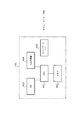
図2は、本実施の形態に係るIP電話101の構成を示すブロック図である。なお、IP電話102についても、IP電話101と同様の構成を有する。
FIG. 2 is a block diagram showing a configuration of
IP電話101は、CPU201がROM202に格納したプログラムを読み込んで実行することにより、IP電話機能、FAX機能、電子メール機能を初めとした各種の搭載機能を実現する。ROM202はIP電話機能、FAX機能、電子メール機能等を提供するアプリケーションプログラムを格納する。なお、RAM203はCPU201の作業エリアとなる。
The IP
IP電話101は、音声通話のためのマイク及びスピーカとなる音声入出力部204、着信者の連絡先情報を初めとした各種情報を表示する表示部205、テンキー、ボタン、ソフトスイッチ等で構成され入力部206を備える。また、FAXとして送信原稿をスキャンする読取部207、受信データを印刷する記録部208を備える。
The
IP電話101は、外部I/F制御部209を介してPSTN網107並びにIP網106に接続可能に構成されている。外部I/F制御部209は、CPU201からの制御によりPSTN制御部211又はネットワーク制御部212に接続を切り換える。PSTN制御部211はPSTN網107に対する回線制御を行い、ネットワーク制御部212はIP網106に対する送受信制御を行う。
The
CPU201は、ENUMサーバ103へ宛先端末に対応するNAPTRレコードを問い合わせるENUMクエリーの送出やそのENUMクエリーに対する応答(ENUM応答)の受信、並びに、DNSサーバ104へIPアドレスを問い合わせるIPアドレス問合せの送出やそのIPアドレス問合せに対する応答(IPアドレス応答)の受信の制御を行う。
The
表示部205は、LCD等の液晶ディスプレイで構成される。表示部205は、本IP電話101の現在のステータスを表示すると共に、入力された電話番号等を表示する。また、Webサーバ105からダウンロードしたHTML文書を表示する。さらに、ENUM応答に基づいて着信者の連絡先情報を表示する。
The
図3は、本実施の形態に係るIP電話101の外観を示す正面図である。なお、IP電話102についても、IP電話101と同様の構成を有する。
FIG. 3 is a front view showing the appearance of
同図に示すように、IP電話101は、オペレータの音声を受け付ける受話器301を備えている。また、電話番号等を受け付けるテンキー302を備えている。さらに、テンキー302の右側に留守番電話に切り替える留守キー303及び音声を外部出力に切り替えるスピーカキー304を備えている。さらに、テンキー302の上側にワンタッチで発信可能なワンタッチ機能に代表される各種機能が設定可能なファンクションキー305を備えている。さらに、側面部にIP網106に接続されるLANとのインターフェイス(LANI/F)306を備えている。
As shown in the figure, the
ファンクションキー305の上側に、液晶ディスプレイ等で構成される表示部205が設けられている。表示部205は、例えば、Webサーバ105からダウンロードした発信者情報(発信者番号や氏名など)が表示される。
A
図4は、本実施の形態に係るIP電話システムにおけるENUMサーバ103の代表的な構成を示すブロック図である。なお、DNSサーバ104やWebサーバ105についても、DBに登録されるデータの内容が異なる他は、同様のハードウエア構成を有する。
FIG. 4 is a block diagram showing a typical configuration of
同図に示すように、ENUMサーバ103は、サーバ本体の全体を制御するCPU401を備えている。このCPU401にメモリ402が接続されている。メモリ402は、CPU401が読み込んで実行する本ENUMサーバ103の制御プログラムが格納されるROMとしての機能と、CPU401が制御プログラムを実行する際のワークメモリとして機能するRAMとしての機能とを備える。
As shown in the figure, the
また、CPU401にデータベース(DB)403が接続されている。DB403は、NAPTRレコードを登録している。CPU401は、例えば、IP電話101からENUMクエリーを受け付けると、DB403から該当するNAPTRレコードを検索してENUMクエリーを送出してきたIP電話101に返送する。
A database (DB) 403 is connected to the
さらに、CPU401に入出力装置404が接続されている。入出力装置404は、例えば、キーボード等の入力装置と、ディスプレイ等の出力装置とから構成される。入力装置は、例えば、DB403に登録されるデータの内容を追加、編集する場合に利用される。出力装置は、例えば、DB403に登録されるデータの内容をENUMサーバ103の管理者等が確認する場合に利用される。
Further, an input /
さらに、CPU401にネットワークインターフェイス(I/F)405が接続されている。ネットワークI/F405は、本ENUMサーバ103が接続されるIP網106とのインターフェイスである。
Further, a network interface (I / F) 405 is connected to the
図5は、本実施の形態に係るENUMサーバ103のDB403に登録されたNAPTRレコードの一例を示す図である。同図においては、電話番号「0310000000」及び「0310000001」に対応した各ドメイン名に関して登録されたNAPTRレコードを示している。
FIG. 5 is a diagram showing an example of the NAPTR record registered in the
同図においては、電話番号「0310000000」に対応したドメイン名「0.0.0.0.0.0.0.1.3.1.8.e164.arpa」に対して「81310000000@tokyo.sip.jp」及び「//www.tokyo.sip.com/user81310000000.html」の2つのURIが登録されている。前者のServiceフィールドにはSIPプロトコルに対応可能であることを示す「E2U+sip」と記述され、後者のServiceフィールドにはhttpプトロコルに対応可能である旨を示す「E2U+http」と記述されている。 In the figure, the domain name “0.0.0.0.0.0.0.1.3.1.1.8.e164.arpa” corresponding to the telephone number “0310000000” is “81310000000 @ tokyo. Two URIs of “sip.jp” and “//www.tokyo.sip.com/user81310000000.html” are registered. The former Service field is described as “E2U + ship” indicating that the SIP protocol can be supported, and the latter Service field is described as “E2U + http” indicating that the HTTP protocol can be supported.
また、電話番号「0310000001」に対応したドメイン名「1.0.0.0.0.0.0.1.3.1.8.e164.arpa」に対してURI「81310000001@tokyo.mail.com」及び「//www.tokyo.sip.com/user81310000001.html」に2つのURIが登録されている。前者のServiceフィールドにはSIPプロトコルに対応可能であることを示す「E2U+sip」と記述され、後者のServiceフィールドにはhttpプトロコルに対応可能である旨を示す「E2U+http」と記述されている。 Also, the URI “81310000001@tokyo.mail.com” is associated with the domain name “1.0.0.0.0.0.0.1.3.3.1.8e164.arpa” corresponding to the telephone number “0310000001”. com "and" //www.tokyo.sip.com/user81310000001.html "are registered. The former Service field is described as “E2U + ship” indicating that the SIP protocol can be supported, and the latter Service field is described as “E2U + http” indicating that the HTTP protocol can be supported.
次に、本実施の形態に係るIP電話システムにおいて、IP電話101が着信者の連絡先情報を表示してユーザが連絡先を選択する動作フローについて、図6を参照して説明する。
Next, in the IP telephone system according to the present embodiment, an operation flow in which
なお、前提として、ENUMサーバ103のDB403には、着信者(IP電話102のユーザ)のコンタクトアドレス(ドメイン化電話番号)に対応させて幾つかのNAPTRレコードが登録されているものとする。
As a premise, it is assumed that several NAPTR records are registered in the
発信者がIP電話101のテンキー302を操作して着信者の電話番号(本例では一般電話番号)をダイヤルすると、IP電話101はダイヤル入力された電話番号を受け付ける(S101)。
When the caller operates the
次に、IP電話101は相手の連絡先情報を取得する処理を実行する(S102)。着信者の電話番号(0455445×××)がダイヤル入力されると、入力された相手電話番号をENUMサーバ103のDB403に登録されているドメイン名に変換する。具体的には次の処理を実行する。入力された「0455445×××」を国番号付きのE.164番号である「+81−4−55445×××」に変換し、先頭の+と数字を残して「+81455445×××」とする。そして、数字以外の文字を抹消して数字間にドットを挿入して「8.1.4.5.5.4.4.5.×.×.×」とする。次に、数字を逆順にして最後に文字列.e164.arpaを追加する。これにより、ドメイン名である「×.×.×.5.4.4.5.5.4.1.8.e164.arpa」を得る。
Next, the
IP電話101は、ダイヤルされた相手電話番号からドメイン名を生成したら、当該ドメイン名にてNAPTRレコードを問い合わせるENUMクエリーをENUMサーバ103に対して送出する。
After generating the domain name from the dialed telephone number,
ENUMサーバ103は、IP電話101から送信されたENUMクエリーを受け付ける。そして、ENUMクエリーに含まれた問い合わせドメイン名である「×.×.×.5.4.4.5.5.4.1.8.e164.arpa」に対応するNAPTRレコードをDB403から検索する。この結果、図7に示すNAPTRレコードが検索結果として取得される。ENUMサーバ103は、当該NAPTRレコードを含むENUM応答をIP電話101に返信する。
IP電話101は、ENUMサーバ103からENUMクエリーに対するENUM応答として図7に示すNAPTRレコードを取得する。
The
図7はIP電話102のユーザである着信者がコンタクトアドレスとなる電話番号(ドメイン化電話番号)に対応させて自分で指定した連絡先情報をNAPTRレコードに埋め込んだ具体例である。図7に示すNAPTRレコードは、第1行、第2行にSIPを用いる連絡先情報(太郎電話、花子電話)が記述され、第3行に電子メールの連絡先情報(メール)が記述されている。さらに、第4行には一般電話の連絡先情報(自宅電話)が記述され、第5行にインターネットFXAによる連絡先情報(FAX)が記述されている。すなわち、「×.×.×.5.4.4.5.5.4.1.8.e164.arpa」のコンタクトアドレスを持つ着信者は、SIPによる2つのIP電話番号、1つの電子メールアドレス、1つの一般電話番号、1つのFAX番号を自己の宛先番号として登録していることになる。
FIG. 7 shows a specific example in which contact information specified by the called party corresponding to the telephone number (domainized telephone number) that is the contact address of the
IP電話101は、受信したNAPTRレコードから第1行目を取り出す(S103)。具体的には、少なくともNAPTRレコードの第1行目に埋め込まれた連絡先情報を取り出す。本例では、宛先番号「sip:info@sip.aaaa.com」と、当該宛先番号を使用したサービス名称「太郎電話」を取り出すものとする。図7に示すように宛先番号の後にサービス名称を設定している。サービス名称は着信者が任意に定めたものである。
IP電話101は、この取り出した連絡先情報を宛先データとして表示部205のLCDバッファ(図示せず)へセットする(S104)。NAPTRレコードの第1行目の取り出しが終了したら、以後同様にして処理対象行を順次繰り下げながら、各行から連絡先情報を取り出す(S103、S104、S105)。
ステップS102で取得したNAPTRレコードの全ての行から連絡先情報を取り出したならば(S105)、表示部205のLCDにサービス名称を一覧表示させる(S106)。 If the contact information is extracted from all the rows of the NAPTR record acquired in step S102 (S105), a list of service names is displayed on the LCD of the display unit 205 (S106).
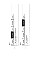
図8(a)(b)は着信者のサービス名称を一覧表示させたLCD画面の例を示している。サービス名称として「太郎電話」「花子電話」「メール」「自宅電話」「FAX」が表示されている。図8(a)では「花子電話」を発信者が選択した状態を示している。サービス名称の選択は入力部206から行う。選択されたサービス名称(花子電話)を強調表示(本例では反転表示であるがこれに限定されない)し、このサービス名称に対応した宛先番号(05012345678@sip.aaaa.com)を、サービス名称(花子電話)の下に表示させる。図8(b)は「自宅電話」を選択した状態を示している。
FIGS. 8A and 8B show examples of LCD screens displaying a list of service names of recipients. “Taro phone”, “Hanako phone”, “mail”, “home phone”, and “FAX” are displayed as service names. FIG. 8A shows a state where the caller has selected “Hanako Telephone”. The service name is selected from the
IP電話101は、表示部205のLCDでサービス名称が選択されてスタートボタン(図示していない)が押下されると、サービス名称に応じたアクセス方法にて宛先番号に対して発信処理する。例えば、「太郎電話」が選択された場合は、宛先番号「info@sip.aaaa.com!」のIPアドレスをDNSサーバ104に問い合わせ、IP電話102のIPアドレスを取得する。次に、取得したIPアドレスを発信先アドレスとしてINVITEリクエストを送出する。INVITEリクエストはIPパケットの形式で送られる。なお、SIPサーバが仲介して呼接続を行う場合は、DNSサーバ104にIPアドレスを問い合わせる処理は必要ない。以下、SIPに基づくシグナリングが実行されてセッションが確立して通話可能な状態になる。又は「自宅電話」が選択された場合は、PSTN網107に対して一般電話番号で発信する。「メール」が選択された場合は電子メール機能が起動されて本文の入力及びメール送信が行われる。これらの発信処理は発信手段としてのCPU201が行う。
When a service name is selected on the LCD of the
このように、本実施の形態によれば、発信者がIP電話101から着信者の1つの電話番号を入力しただけで、表示部205に着信者の連絡先情報となるサービス名称を一覧表示できる。そして、一覧表示されたサービス名称の中から1つを選択すると、対応する宛先番号を表示することができる。発信者は宛先番号まで確認の上、着信者の指定する連絡先に対して発信することができる。また、着信者が任意に定めたサービス名称(太郎電話、花子電話等)を発信者の表示部205に表示できるので、宛先番号を列記する場合に比べて、宛先番号を選択する際の判断がより正確かつ容易になる。
As described above, according to the present embodiment, the service name that is the contact information of the callee can be displayed in a list on the
なお、図9に示すように、着信者が任意に定めたサービス名称に代えて、NAPTRレコードに記述されたサービス名(sip,mailto,tel,ifax)を一覧表示するようにしても良い。図9に例示するように、同じサービス名称(sip)が複数存在する場合は、sip1,sip2のように連続番号を付して違いを示すようにしても良い。 As shown in FIG. 9, a list of service names (sip, mailto, tel, ifax) described in the NAPTR record may be displayed instead of the service name arbitrarily determined by the callee. As illustrated in FIG. 9, when there are a plurality of the same service names (sip), a serial number such as sip1 and sip2 may be attached to indicate the difference.
本発明に係るIP通信装置によれば、発信者が着信者の1つのコンタクトアドレスを入力すると、着信者側が登録しているすべての連絡先情報を取り込んで画面表示でき、その中から発信者が選んだ連絡先に対して発信可能である。 According to the IP communication device according to the present invention, when the caller enters a single contact address of callee, the screen can display capture all contact information called party is registered, callers from its You can make calls to selected contacts.
101、102 IP電話
103 ENUMサーバ
104 DNSサーバ
105 Webサーバ
106 IPネットワーク
107 PSTN網
108 一般電話機
201 CPU
202 ROM
203 RAM
204 音声入出力部
205 表示部
206 入力部
207 読取部
208 記録部
209 外部I/F制御部
211 PSTN制御部
212 ネットワーク制御部
101, 102
202 ROM
203 RAM
204 voice input /
Claims (5)
相手の接続番号を入力する入力手段と、入力された相手の接続番号に基づいてENUMサーバから相手のNAPTRレコードを取得するデータ取得手段と、前記取得したすべてのNAPTRレコードから相手にアクセスするアクセス方法を表すサービス名称を取り出して前記サービス名称をディスプレイに表示させる制御手段と、表示されたサービス名称の中から選択されたサービス名称に対応するNAPTRレコードの連絡先情報に基づいて相手端末へ発信する発信手段と、を具備したIP通信装置。 An IP communication apparatus that stores an NAPTR record including contact information to the IP communication apparatus and connects the ENUM server that returns the NAPTR record in response to an inquiry from the IP communication apparatus via an IP network,
Input means for inputting the other party's connection number, data obtaining means for obtaining the other party's NAPTR record from the ENUM server based on the inputted other party's connection number, and an access method for accessing the other party from all the obtained NAPTR records The control means for taking out the service name representing the service name and displaying the service name on the display, and the transmission to be sent to the partner terminal based on the contact information of the NAPTR record corresponding to the service name selected from the displayed service names And an IP communication apparatus.
入力された相手の接続番号に基づいてENUMサーバに問合せて相手のNAPTRレコードを取得し、前記取得したすべてのNAPTRレコードから相手にアクセスするアクセス方法を表すサービス名称を取り出して前記サービス名称をディスプレイに一覧表示し、表示されたサービス名称の中から選択されたサービス名称に対応するNAPTRレコードの連絡先情報に基づいて相手端末へ発信することを特徴とした連絡先表示方法。 A method for displaying a destination of an IP communication device connected via an IP network to an ENUM server for storing a NAPTR record including contact information to the IP communication device and returning the NAPTR record in response to an inquiry from the IP communication device. ,
An ENUM server is inquired based on the input connection number of the other party to obtain the NAPTR record of the other party , a service name indicating an access method for accessing the other party is extracted from all the obtained NAPTR records, and the service name is displayed on the display. A contact display method characterized in that a list is displayed and a call is made to a partner terminal based on contact information in a NAPTR record corresponding to a service name selected from the displayed service names .
Priority Applications (4)
| Application Number | Priority Date | Filing Date | Title |
|---|---|---|---|
| JP2004295171A JP4522811B2 (en) | 2004-10-07 | 2004-10-07 | IP communication apparatus and contact display method |
| US11/235,275 US20060077966A1 (en) | 2004-10-07 | 2005-09-27 | IP telephone apparatus |
| EP05021722A EP1646211A1 (en) | 2004-10-07 | 2005-10-05 | IP telephone apparatus with display for selecting of contact information |
| KR1020050093916A KR100796279B1 (en) | 2004-10-07 | 2005-10-06 | Ip telephone apparatus |
Applications Claiming Priority (1)
| Application Number | Priority Date | Filing Date | Title |
|---|---|---|---|
| JP2004295171A JP4522811B2 (en) | 2004-10-07 | 2004-10-07 | IP communication apparatus and contact display method |
Publications (3)
| Publication Number | Publication Date |
|---|---|
| JP2006109260A JP2006109260A (en) | 2006-04-20 |
| JP2006109260A5 JP2006109260A5 (en) | 2007-11-22 |
| JP4522811B2 true JP4522811B2 (en) | 2010-08-11 |
Family
ID=35517470
Family Applications (1)
| Application Number | Title | Priority Date | Filing Date |
|---|---|---|---|
| JP2004295171A Expired - Fee Related JP4522811B2 (en) | 2004-10-07 | 2004-10-07 | IP communication apparatus and contact display method |
Country Status (4)
| Country | Link |
|---|---|
| US (1) | US20060077966A1 (en) |
| EP (1) | EP1646211A1 (en) |
| JP (1) | JP4522811B2 (en) |
| KR (1) | KR100796279B1 (en) |
Families Citing this family (10)
| Publication number | Priority date | Publication date | Assignee | Title |
|---|---|---|---|---|
| US8085757B2 (en) * | 2005-11-07 | 2011-12-27 | At&T Intellectual Property I, L.P. | Caller-controlled routing to non-SIP/non-TEL URI destinations for an IMS-based ENUM query |
| JP2007324838A (en) * | 2006-05-31 | 2007-12-13 | Pioneer Electronic Corp | Telephone, telephone number converting method, and telephone number conversion processing program |
| JP2007324837A (en) * | 2006-05-31 | 2007-12-13 | Pioneer Electronic Corp | Telephone, telephone number converting method, and telephone number conversion processing program |
| CN101518036B (en) * | 2006-09-27 | 2013-05-22 | 日本电气株式会社 | Communication device and communication method |
| KR100847873B1 (en) * | 2006-12-19 | 2008-07-23 | 삼성전자주식회사 | Call setup method and terminal in internet protocol network |
| KR100883687B1 (en) | 2007-01-19 | 2009-02-20 | (주)드림투리얼리티 | IP phone linkage system for contents output |
| US9049209B2 (en) * | 2007-05-08 | 2015-06-02 | At&T Intellectual Property I, L.P. | Methods and apparatus to route a communication session in an internet protocol (IP) multimedia subsystem (IMS) network |
| EP1993267B1 (en) * | 2007-05-16 | 2013-01-02 | Telnic Limited | Contact information retrieval system and communication system using the same |
| DE102007030822A1 (en) * | 2007-07-03 | 2009-01-15 | Vodafone Holding Gmbh | A method for providing a selection of possible communication channels for establishing a communication connection between terminals |
| SE534639C2 (en) | 2009-09-08 | 2011-11-01 | Telepo Ab | routing Service |
Citations (5)
| Publication number | Priority date | Publication date | Assignee | Title |
|---|---|---|---|---|
| JPH11232193A (en) * | 1998-02-12 | 1999-08-27 | Sony Corp | Device and method for information processing, information processing system and providing medium |
| JP2000089879A (en) * | 1998-09-08 | 2000-03-31 | Nec Corp | Display generation method and device therefor |
| JP2002077445A (en) * | 2000-09-05 | 2002-03-15 | Nippon Telegraph & Telephone East Corp | Address search and connection system |
| JP2004153317A (en) * | 2002-10-28 | 2004-05-27 | Nippon Telegr & Teleph Corp <Ntt> | Method for selecting terminal medium, method for call originating, communication medium selector and terminal medium selecting system |
| JP2006041915A (en) * | 2004-07-27 | 2006-02-09 | Fuji Xerox Co Ltd | Information communication device and control method thereof |
Family Cites Families (10)
| Publication number | Priority date | Publication date | Assignee | Title |
|---|---|---|---|---|
| US6498797B1 (en) * | 1997-11-14 | 2002-12-24 | At&T Corp. | Method and apparatus for communication services on a network |
| US6795429B1 (en) * | 1999-09-27 | 2004-09-21 | 3Com Corporation | System and method for associating notes with a portable information device on a network telephony call |
| KR100367591B1 (en) * | 2000-04-28 | 2003-01-10 | 엘지전자 주식회사 | Mail service apparatus and method for communication terminal equipmetnt based on internnet protocol |
| US20040047341A1 (en) | 2000-12-21 | 2004-03-11 | Jens Staack | Over-the air (ota) service provisioning in a mobile communications system |
| KR100438234B1 (en) * | 2000-12-28 | 2004-07-02 | 엘지전자 주식회사 | Voice and facsimile subscriber apparatus for internet netwokr |
| US20030074461A1 (en) * | 2001-10-09 | 2003-04-17 | I-Dns.Net International Pte. Ltd. | Method of mapping names or identifiers to telecommunications network resource locations |
| US8295270B2 (en) * | 2002-05-16 | 2012-10-23 | International Business Machines Corporation | Internet telephony system for enabling internet telephone access from traditional telephone interface |
| US7320026B2 (en) * | 2002-06-27 | 2008-01-15 | At&T Bls Intellectual Property, Inc. | Intersystem messaging using ENUM standard |
| KR100485692B1 (en) * | 2002-09-12 | 2005-04-27 | (주)씨앤에스 테크놀로지 | The busy sub-input and information exchange method using sub-input system of IP terminal with LCD |
| JP4080362B2 (en) | 2003-03-25 | 2008-04-23 | 株式会社リコー | Image forming system |
-
2004
- 2004-10-07 JP JP2004295171A patent/JP4522811B2/en not_active Expired - Fee Related
-
2005
- 2005-09-27 US US11/235,275 patent/US20060077966A1/en not_active Abandoned
- 2005-10-05 EP EP05021722A patent/EP1646211A1/en not_active Withdrawn
- 2005-10-06 KR KR1020050093916A patent/KR100796279B1/en not_active IP Right Cessation
Patent Citations (5)
| Publication number | Priority date | Publication date | Assignee | Title |
|---|---|---|---|---|
| JPH11232193A (en) * | 1998-02-12 | 1999-08-27 | Sony Corp | Device and method for information processing, information processing system and providing medium |
| JP2000089879A (en) * | 1998-09-08 | 2000-03-31 | Nec Corp | Display generation method and device therefor |
| JP2002077445A (en) * | 2000-09-05 | 2002-03-15 | Nippon Telegraph & Telephone East Corp | Address search and connection system |
| JP2004153317A (en) * | 2002-10-28 | 2004-05-27 | Nippon Telegr & Teleph Corp <Ntt> | Method for selecting terminal medium, method for call originating, communication medium selector and terminal medium selecting system |
| JP2006041915A (en) * | 2004-07-27 | 2006-02-09 | Fuji Xerox Co Ltd | Information communication device and control method thereof |
Also Published As
| Publication number | Publication date |
|---|---|
| EP1646211A1 (en) | 2006-04-12 |
| US20060077966A1 (en) | 2006-04-13 |
| JP2006109260A (en) | 2006-04-20 |
| KR100796279B1 (en) | 2008-01-21 |
| KR20060052078A (en) | 2006-05-19 |
Similar Documents
| Publication | Publication Date | Title |
|---|---|---|
| KR100675304B1 (en) | Ip telephone system and calling method | |
| KR100720617B1 (en) | Ip telephone apparatus | |
| US8045541B2 (en) | IP telephone system, IP telephone apparatus and method for identifying destination user | |
| KR100720615B1 (en) | Ip telephone apparatus | |
| KR100796279B1 (en) | Ip telephone apparatus | |
| KR100671532B1 (en) | Ip telephone system, ip telephone apparatus and method for identifying destination user | |
| KR100671507B1 (en) | Ip telephone system, ip telephone apparatus and method for identifying destination user | |
| US8089954B2 (en) | IP telephone system, IP telephone apparatus and communications method | |
| KR100648591B1 (en) | Ip telephone system, ip telephone apparatus and method for recording message | |
| KR100675308B1 (en) | Ip terminal apparatus |
Legal Events
| Date | Code | Title | Description |
|---|---|---|---|
| A521 | Request for written amendment filed |
Free format text: JAPANESE INTERMEDIATE CODE: A523 Effective date: 20071004 |
|
| A621 | Written request for application examination |
Free format text: JAPANESE INTERMEDIATE CODE: A621 Effective date: 20071004 |
|
| A977 | Report on retrieval |
Free format text: JAPANESE INTERMEDIATE CODE: A971007 Effective date: 20090806 |
|
| A131 | Notification of reasons for refusal |
Free format text: JAPANESE INTERMEDIATE CODE: A131 Effective date: 20090825 |
|
| A521 | Request for written amendment filed |
Free format text: JAPANESE INTERMEDIATE CODE: A523 Effective date: 20091002 |
|
| TRDD | Decision of grant or rejection written | ||
| A01 | Written decision to grant a patent or to grant a registration (utility model) |
Free format text: JAPANESE INTERMEDIATE CODE: A01 Effective date: 20100518 |
|
| A01 | Written decision to grant a patent or to grant a registration (utility model) |
Free format text: JAPANESE INTERMEDIATE CODE: A01 |
|
| A61 | First payment of annual fees (during grant procedure) |
Free format text: JAPANESE INTERMEDIATE CODE: A61 Effective date: 20100526 |
|
| R150 | Certificate of patent or registration of utility model |
Free format text: JAPANESE INTERMEDIATE CODE: R150 |
|
| FPAY | Renewal fee payment (event date is renewal date of database) |
Free format text: PAYMENT UNTIL: 20130604 Year of fee payment: 3 |
|
| LAPS | Cancellation because of no payment of annual fees |