JP4521720B2 - メッシュ及びインピンジメント冷却を備えた高温ガス流路部品 - Google Patents
メッシュ及びインピンジメント冷却を備えた高温ガス流路部品 Download PDFInfo
- Publication number
- JP4521720B2 JP4521720B2 JP2004334184A JP2004334184A JP4521720B2 JP 4521720 B2 JP4521720 B2 JP 4521720B2 JP 2004334184 A JP2004334184 A JP 2004334184A JP 2004334184 A JP2004334184 A JP 2004334184A JP 4521720 B2 JP4521720 B2 JP 4521720B2
- Authority
- JP
- Japan
- Prior art keywords
- wall
- dimples
- cooling
- cooling holes
- outer portion
- Prior art date
- Legal status (The legal status is an assumption and is not a legal conclusion. Google has not performed a legal analysis and makes no representation as to the accuracy of the status listed.)
- Expired - Fee Related
Links
Images


Classifications
-
- F—MECHANICAL ENGINEERING; LIGHTING; HEATING; WEAPONS; BLASTING
- F01—MACHINES OR ENGINES IN GENERAL; ENGINE PLANTS IN GENERAL; STEAM ENGINES
- F01D—NON-POSITIVE DISPLACEMENT MACHINES OR ENGINES, e.g. STEAM TURBINES
- F01D5/00—Blades; Blade-carrying members; Heating, heat-insulating, cooling or antivibration means on the blades or the members
- F01D5/12—Blades
- F01D5/14—Form or construction
- F01D5/18—Hollow blades, i.e. blades with cooling or heating channels or cavities; Heating, heat-insulating or cooling means on blades
- F01D5/187—Convection cooling
- F01D5/188—Convection cooling with an insert in the blade cavity to guide the cooling fluid, e.g. forming a separation wall
- F01D5/189—Convection cooling with an insert in the blade cavity to guide the cooling fluid, e.g. forming a separation wall the insert having a tubular cross-section, e.g. airfoil shape
-
- F—MECHANICAL ENGINEERING; LIGHTING; HEATING; WEAPONS; BLASTING
- F05—INDEXING SCHEMES RELATING TO ENGINES OR PUMPS IN VARIOUS SUBCLASSES OF CLASSES F01-F04
- F05D—INDEXING SCHEME FOR ASPECTS RELATING TO NON-POSITIVE-DISPLACEMENT MACHINES OR ENGINES, GAS-TURBINES OR JET-PROPULSION PLANTS
- F05D2260/00—Function
- F05D2260/20—Heat transfer, e.g. cooling
- F05D2260/221—Improvement of heat transfer
- F05D2260/2212—Improvement of heat transfer by creating turbulence
-
- F—MECHANICAL ENGINEERING; LIGHTING; HEATING; WEAPONS; BLASTING
- F05—INDEXING SCHEMES RELATING TO ENGINES OR PUMPS IN VARIOUS SUBCLASSES OF CLASSES F01-F04
- F05D—INDEXING SCHEME FOR ASPECTS RELATING TO NON-POSITIVE-DISPLACEMENT MACHINES OR ENGINES, GAS-TURBINES OR JET-PROPULSION PLANTS
- F05D2260/00—Function
- F05D2260/20—Heat transfer, e.g. cooling
- F05D2260/221—Improvement of heat transfer
- F05D2260/2214—Improvement of heat transfer by increasing the heat transfer surface
- F05D2260/22141—Improvement of heat transfer by increasing the heat transfer surface using fins or ribs
-
- Y—GENERAL TAGGING OF NEW TECHNOLOGICAL DEVELOPMENTS; GENERAL TAGGING OF CROSS-SECTIONAL TECHNOLOGIES SPANNING OVER SEVERAL SECTIONS OF THE IPC; TECHNICAL SUBJECTS COVERED BY FORMER USPC CROSS-REFERENCE ART COLLECTIONS [XRACs] AND DIGESTS
- Y02—TECHNOLOGIES OR APPLICATIONS FOR MITIGATION OR ADAPTATION AGAINST CLIMATE CHANGE
- Y02T—CLIMATE CHANGE MITIGATION TECHNOLOGIES RELATED TO TRANSPORTATION
- Y02T50/00—Aeronautics or air transport
- Y02T50/60—Efficient propulsion technologies, e.g. for aircraft
Description
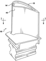
12 部品の壁
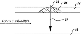
14 壁の内側部分
16 壁の外側部分
18 ピン
20 メッシュ冷却構成
22 流れチャネル
24 ディンプル
32 吹出し冷却孔
33 インピンジメント冷却孔
34 皮膜
35 冷却孔
37 インピンジメント噴流
100 穿孔工具
Claims (10)
- 内側部分(14)及び外側部分(16)を有する少なくとも1つの壁(12)と、
前記壁の内側及び外側部分間で延びる複数のピン(18)と、を含み、
前記ピンが、複数の流れチャネル(22)を含むメッシュ冷却構成(20)を形成し、前記流れチャネルが、互いにほぼ平行な第1の組の流れチャネル(26)と互いにほぼ平行に延びる第2の組の流れチャネル(28)とを含み、前記第1及び第2の組の流れチャネルが、複数の交差位置(30)において互いに交差して前記メッシュ冷却構成を形成し、
前記壁の内側部分には複数のディンプル(24)が形成され、前記ディンプルの少なくとも1つが、前記壁の内側部分を貫通してインピンジメント冷却孔(33)を形成し、また前記ディンプルの少なくとも1つが、前記交差位置のそれぞれの1つに配置されている、
高温ガス流路部品(10)。 - 前記ディンプル(24)の各々が、複数のインピンジメント冷却孔(33)を形成するように前記壁(12)の内側部分(14)を貫通している、請求項1記載の高温ガス流路部品(10)。
- 前記壁(12)の外側部分(16)には複数の冷却孔(35)が形成され、前記冷却孔(35)の各々が、前記ディンプル(24)のそれぞれの1つと整列している、請求項1記載の高温ガス流路部品(10)。
- 前記壁(12)の外側部分(16)上に少なくとも1つの皮膜(34)をさらに含み、
前記壁の外側部分には複数のディンプル(24)が形成され、
前記ディンプルの少なくとも1つが、前記壁の外側部分を貫通して吹出し冷却孔(32)を形成し、前記皮膜が前記吹出し冷却孔を少なくとも部分的に覆っている、
請求項1記載の高温ガス流路部品(10)。 - 複数のディンプル(24)が形成された内側部分(14)と外側部分(16)とを有する少なくとも1つの壁(12)を含む部品(10)内に複数の冷却孔(33)を形成する方法であって、
前記ディンプルの1つに穿孔工具(100)を心合わせする段階と、
前記穿孔工具を用いて、前記ディンプルにおいて壁の内側部分を貫通する少なくとも1つのインピンジメント冷却孔(33)を穿孔する段階と、
前記心合わせする段階及び穿孔する段階を複数のディンプルに対して反復して、前記壁の内側部分に複数のインピンジメント冷却孔を穿孔する段階と、
を含む方法。 - 前記心合わせする段階が、前記ディンプル(24)のそれぞれの1つの中心(101)の近傍に前記穿孔工具を心合わせする段階を含む、請求項5記載の方法。
- 前記穿孔工具(100)が、レーザ、放電加工装置(100)及び電子ビーム(EBEAM)加工装置(100)からなる群から選択される、請求項5記載の方法。
- 前記穿孔する段階が、前記穿孔工具(100)を用いて、その各々が前記インピンジメント冷却孔(33)のそれぞれの1つと整列した複数の冷却孔(35)を前記壁(12)の外側部分(16)に穿孔する段階をさらに含む、請求項5記載の方法。
- 前記穿孔する段階を行った後に前記壁の外側部分(16)上に断熱皮膜を形成する段階をさらに含む、請求項8記載の方法。
- 前記壁(12)の外側部分(16)には複数のディンプル(24)が形成され、前記壁の内側及び外側部分のディンプルが整列しており、また前記冷却孔の各々が、前記壁の外側部分のディンプルのそれぞれの1つを貫通して形成された吹出し冷却孔(32)である、請求項8記載の方法。
Applications Claiming Priority (2)
| Application Number | Priority Date | Filing Date | Title |
|---|---|---|---|
| US10/720,045 US7186084B2 (en) | 2003-11-19 | 2003-11-19 | Hot gas path component with mesh and dimpled cooling |
| US10/881,506 US7182576B2 (en) | 2003-11-19 | 2004-06-29 | Hot gas path component with mesh and impingement cooling |
Publications (2)
| Publication Number | Publication Date |
|---|---|
| JP2005147157A JP2005147157A (ja) | 2005-06-09 |
| JP4521720B2 true JP4521720B2 (ja) | 2010-08-11 |
Family
ID=34437432
Family Applications (1)
| Application Number | Title | Priority Date | Filing Date |
|---|---|---|---|
| JP2004334184A Expired - Fee Related JP4521720B2 (ja) | 2003-11-19 | 2004-11-18 | メッシュ及びインピンジメント冷却を備えた高温ガス流路部品 |
Country Status (2)
| Country | Link |
|---|---|
| EP (1) | EP1533481A3 (ja) |
| JP (1) | JP4521720B2 (ja) |
Families Citing this family (4)
| Publication number | Priority date | Publication date | Assignee | Title |
|---|---|---|---|---|
| US7186084B2 (en) * | 2003-11-19 | 2007-03-06 | General Electric Company | Hot gas path component with mesh and dimpled cooling |
| US20070201980A1 (en) * | 2005-10-11 | 2007-08-30 | Honeywell International, Inc. | Method to augment heat transfer using chamfered cylindrical depressions in cast internal cooling passages |
| EP1953342A1 (de) * | 2007-02-01 | 2008-08-06 | Siemens Aktiengesellschaft | Turbinenschaufel |
| US9638057B2 (en) | 2013-03-14 | 2017-05-02 | Rolls-Royce North American Technologies, Inc. | Augmented cooling system |
Citations (2)
| Publication number | Priority date | Publication date | Assignee | Title |
|---|---|---|---|---|
| US5690472A (en) * | 1992-02-03 | 1997-11-25 | General Electric Company | Internal cooling of turbine airfoil wall using mesh cooling hole arrangement |
| JP2000130760A (ja) * | 1998-07-20 | 2000-05-12 | General Electric Co <Ge> | ディンプルを設けたインピンジメントバッフル |
Family Cites Families (6)
| Publication number | Priority date | Publication date | Assignee | Title |
|---|---|---|---|---|
| US4407632A (en) * | 1981-06-26 | 1983-10-04 | United Technologies Corporation | Airfoil pedestaled trailing edge region cooling configuration |
| US5931638A (en) * | 1997-08-07 | 1999-08-03 | United Technologies Corporation | Turbomachinery airfoil with optimized heat transfer |
| US6098397A (en) * | 1998-06-08 | 2000-08-08 | Caterpillar Inc. | Combustor for a low-emissions gas turbine engine |
| US6607355B2 (en) * | 2001-10-09 | 2003-08-19 | United Technologies Corporation | Turbine airfoil with enhanced heat transfer |
| US6974308B2 (en) * | 2001-11-14 | 2005-12-13 | Honeywell International, Inc. | High effectiveness cooled turbine vane or blade |
| US7186084B2 (en) * | 2003-11-19 | 2007-03-06 | General Electric Company | Hot gas path component with mesh and dimpled cooling |
-
2004
- 2004-11-17 EP EP04257131A patent/EP1533481A3/en not_active Withdrawn
- 2004-11-18 JP JP2004334184A patent/JP4521720B2/ja not_active Expired - Fee Related
Patent Citations (2)
| Publication number | Priority date | Publication date | Assignee | Title |
|---|---|---|---|---|
| US5690472A (en) * | 1992-02-03 | 1997-11-25 | General Electric Company | Internal cooling of turbine airfoil wall using mesh cooling hole arrangement |
| JP2000130760A (ja) * | 1998-07-20 | 2000-05-12 | General Electric Co <Ge> | ディンプルを設けたインピンジメントバッフル |
Also Published As
| Publication number | Publication date |
|---|---|
| JP2005147157A (ja) | 2005-06-09 |
| EP1533481A2 (en) | 2005-05-25 |
| EP1533481A3 (en) | 2009-11-04 |
Similar Documents
| Publication | Publication Date | Title |
|---|---|---|
| US7182576B2 (en) | Hot gas path component with mesh and impingement cooling | |
| US6984102B2 (en) | Hot gas path component with mesh and turbulated cooling | |
| RU2531712C2 (ru) | Лопатка для газовой турбины с охлаждаемой законцовкой периферической части лопатки | |
| US9127560B2 (en) | Cooled turbine blade and method for cooling a turbine blade | |
| EP1790822B1 (en) | Microcircuit cooling for blades | |
| US6773231B2 (en) | Turbine blade core cooling apparatus and method of fabrication | |
| RU2577688C2 (ru) | Лопатка для турбомашины и турбомашина, содержащая такую лопатку. | |
| KR20060051506A (ko) | 큰 필렛을 가진 에어포일 및 마이크로회로 냉각 | |
| US10001013B2 (en) | Turbine rotor blades with platform cooling arrangements | |
| US9995151B2 (en) | Article and manifold for thermal adjustment of a turbine component | |
| KR20040071045A (ko) | 터빈 블레이드 팁을 위한 마이크로 회로 냉각 | |
| JP2008169845A (ja) | インピンジメント冷却式バケットシュラウド、該シュラウドが組み込まれたタービンロータ並びに冷却方法 | |
| JP2006083851A (ja) | タービンバケット翼形部の後縁のための冷却システム | |
| Wright et al. | Review of platform cooling technology for high pressure turbine blades | |
| US11131199B2 (en) | Impingement cooling with impingement cells on impinged surface | |
| US20120301319A1 (en) | Curved Passages for a Turbine Component | |
| JP4433139B2 (ja) | タービンブレード壁の冷却装置及び製造方法 | |
| JP2010514984A (ja) | 表面に斜めに延びる凹部を備えるコンポーネント、およびタービンの運転方法 | |
| JP4521720B2 (ja) | メッシュ及びインピンジメント冷却を備えた高温ガス流路部品 | |
| US20150198048A1 (en) | Method for producing a stator blade and stator blade | |
| JP2021076115A (ja) | 衝突冷却によってガスタービン/ターボ機械の構成部品を冷却するための装置 | |
| KR20220008914A (ko) | 에어포일용 니어 월 리딩 에지 냉각 채널 | |
| JP2007211618A (ja) | ガスタービン | |
| US20200131913A1 (en) | Method and apparatus for improving cooling of a turbine shroud |
Legal Events
| Date | Code | Title | Description |
|---|---|---|---|
| A621 | Written request for application examination |
Free format text: JAPANESE INTERMEDIATE CODE: A621 Effective date: 20071116 |
|
| TRDD | Decision of grant or rejection written | ||
| A01 | Written decision to grant a patent or to grant a registration (utility model) |
Free format text: JAPANESE INTERMEDIATE CODE: A01 Effective date: 20100427 |
|
| A01 | Written decision to grant a patent or to grant a registration (utility model) |
Free format text: JAPANESE INTERMEDIATE CODE: A01 |
|
| RD02 | Notification of acceptance of power of attorney |
Free format text: JAPANESE INTERMEDIATE CODE: A7422 Effective date: 20100519 |
|
| RD04 | Notification of resignation of power of attorney |
Free format text: JAPANESE INTERMEDIATE CODE: A7424 Effective date: 20100519 |
|
| A61 | First payment of annual fees (during grant procedure) |
Free format text: JAPANESE INTERMEDIATE CODE: A61 Effective date: 20100519 |
|
| R150 | Certificate of patent or registration of utility model |
Free format text: JAPANESE INTERMEDIATE CODE: R150 |
|
| FPAY | Renewal fee payment (event date is renewal date of database) |
Free format text: PAYMENT UNTIL: 20130604 Year of fee payment: 3 |
|
| LAPS | Cancellation because of no payment of annual fees |