JP4518554B2 - Fishing rod - Google Patents
Fishing rod Download PDFInfo
- Publication number
- JP4518554B2 JP4518554B2 JP2004335830A JP2004335830A JP4518554B2 JP 4518554 B2 JP4518554 B2 JP 4518554B2 JP 2004335830 A JP2004335830 A JP 2004335830A JP 2004335830 A JP2004335830 A JP 2004335830A JP 4518554 B2 JP4518554 B2 JP 4518554B2
- Authority
- JP
- Japan
- Prior art keywords
- rod
- solid
- specific gravity
- top guide
- tip
- Prior art date
- Legal status (The legal status is an assumption and is not a legal conclusion. Google has not performed a legal analysis and makes no representation as to the accuracy of the status listed.)
- Expired - Fee Related
Links
- 230000005484 gravity Effects 0.000 claims description 24
- 239000007787 solid Substances 0.000 claims description 20
- 239000012783 reinforcing fiber Substances 0.000 claims description 18
- 230000002093 peripheral effect Effects 0.000 claims description 15
- 239000011347 resin Substances 0.000 claims description 10
- 229920005989 resin Polymers 0.000 claims description 10
- 229920000049 Carbon (fiber) Polymers 0.000 claims description 8
- 210000001217 buttock Anatomy 0.000 claims description 8
- 239000004917 carbon fiber Substances 0.000 claims description 8
- 229920001187 thermosetting polymer Polymers 0.000 claims description 8
- 239000000835 fiber Substances 0.000 claims description 6
- WFKWXMTUELFFGS-UHFFFAOYSA-N tungsten Chemical group [W] WFKWXMTUELFFGS-UHFFFAOYSA-N 0.000 claims description 6
- 229910052721 tungsten Inorganic materials 0.000 claims description 6
- 239000010937 tungsten Substances 0.000 claims description 6
- 238000004804 winding Methods 0.000 claims description 5
- VNWKTOKETHGBQD-UHFFFAOYSA-N methane Chemical group C VNWKTOKETHGBQD-UHFFFAOYSA-N 0.000 claims description 2
- 230000003014 reinforcing effect Effects 0.000 claims 1
- 230000000694 effects Effects 0.000 description 9
- 238000005498 polishing Methods 0.000 description 5
- 239000004593 Epoxy Substances 0.000 description 4
- 241000251468 Actinopterygii Species 0.000 description 3
- 230000004308 accommodation Effects 0.000 description 2
- 238000010304 firing Methods 0.000 description 2
- 239000007788 liquid Substances 0.000 description 2
- XEEYBQQBJWHFJM-UHFFFAOYSA-N Iron Chemical group [Fe] XEEYBQQBJWHFJM-UHFFFAOYSA-N 0.000 description 1
- 239000011248 coating agent Substances 0.000 description 1
- 238000000576 coating method Methods 0.000 description 1
- 239000005002 finish coating Substances 0.000 description 1
- 238000004519 manufacturing process Methods 0.000 description 1
- 239000000463 material Substances 0.000 description 1
- 229910052751 metal Inorganic materials 0.000 description 1
- 239000002184 metal Substances 0.000 description 1
- 238000000034 method Methods 0.000 description 1
- 229910001220 stainless steel Inorganic materials 0.000 description 1
- 239000010935 stainless steel Substances 0.000 description 1
Images
Classifications
-
- A—HUMAN NECESSITIES
- A01—AGRICULTURE; FORESTRY; ANIMAL HUSBANDRY; HUNTING; TRAPPING; FISHING
- A01K—ANIMAL HUSBANDRY; AVICULTURE; APICULTURE; PISCICULTURE; FISHING; REARING OR BREEDING ANIMALS, NOT OTHERWISE PROVIDED FOR; NEW BREEDS OF ANIMALS
- A01K87/00—Fishing rods
- A01K87/04—Fishing-line guides on rods, e.g. tips
-
- A—HUMAN NECESSITIES
- A01—AGRICULTURE; FORESTRY; ANIMAL HUSBANDRY; HUNTING; TRAPPING; FISHING
- A01K—ANIMAL HUSBANDRY; AVICULTURE; APICULTURE; PISCICULTURE; FISHING; REARING OR BREEDING ANIMALS, NOT OTHERWISE PROVIDED FOR; NEW BREEDS OF ANIMALS
- A01K87/00—Fishing rods
- A01K87/002—Fishing rods with the line passing through the hollow rod
-
- B—PERFORMING OPERATIONS; TRANSPORTING
- B32—LAYERED PRODUCTS
- B32B—LAYERED PRODUCTS, i.e. PRODUCTS BUILT-UP OF STRATA OF FLAT OR NON-FLAT, e.g. CELLULAR OR HONEYCOMB, FORM
- B32B38/00—Ancillary operations in connection with laminating processes
- B32B38/08—Impregnating
-
- Y—GENERAL TAGGING OF NEW TECHNOLOGICAL DEVELOPMENTS; GENERAL TAGGING OF CROSS-SECTIONAL TECHNOLOGIES SPANNING OVER SEVERAL SECTIONS OF THE IPC; TECHNICAL SUBJECTS COVERED BY FORMER USPC CROSS-REFERENCE ART COLLECTIONS [XRACs] AND DIGESTS
- Y02—TECHNOLOGIES OR APPLICATIONS FOR MITIGATION OR ADAPTATION AGAINST CLIMATE CHANGE
- Y02P—CLIMATE CHANGE MITIGATION TECHNOLOGIES IN THE PRODUCTION OR PROCESSING OF GOODS
- Y02P60/00—Technologies relating to agriculture, livestock or agroalimentary industries
- Y02P60/60—Fishing; Aquaculture; Aquafarming
-
- Y—GENERAL TAGGING OF NEW TECHNOLOGICAL DEVELOPMENTS; GENERAL TAGGING OF CROSS-SECTIONAL TECHNOLOGIES SPANNING OVER SEVERAL SECTIONS OF THE IPC; TECHNICAL SUBJECTS COVERED BY FORMER USPC CROSS-REFERENCE ART COLLECTIONS [XRACs] AND DIGESTS
- Y10—TECHNICAL SUBJECTS COVERED BY FORMER USPC
- Y10S—TECHNICAL SUBJECTS COVERED BY FORMER USPC CROSS-REFERENCE ART COLLECTIONS [XRACs] AND DIGESTS
- Y10S43/00—Fishing, trapping, and vermin destroying
Landscapes
- Life Sciences & Earth Sciences (AREA)
- Environmental Sciences (AREA)
- Marine Sciences & Fisheries (AREA)
- Animal Husbandry (AREA)
- Biodiversity & Conservation Biology (AREA)
- Fishing Rods (AREA)
Description
本発明は、外周面に釣糸ガイドを装着した穂先竿等に使用される釣り竿用の竿体に関する。 The present invention relates to a fishing rod rod body used for a tip rod or the like having a fishing line guide mounted on its outer peripheral surface.
釣り竿の穂先竿等は、炭素繊維等の強化繊維を引き揃えて、その引き揃え強化繊維にエポキシ等の熱硬化性樹脂を含浸させて形成したプリプレグシートを、所定のテーパ形状をしたマンドレルに巻き付けて、焼成して形成されている(特許文献1参照)。 The tip of a fishing rod is a prepreg sheet formed by aligning reinforcing fibers such as carbon fibers and impregnating the aligned reinforcing fibers with a thermosetting resin such as epoxy, and wraps them around a mandrel with a predetermined taper shape. It is formed by firing (see Patent Document 1).
上記したように、プリプレグを巻回して形成した竿体は、プリプレグ固有の剛性を持つことになり、竿の調子が決まっている。
したがって、竿の曲がりが決まったものになるので、操作性の自由度が低い面があった。また、魚の当たりを捉え易くする為に、極端に先調子の穂先竿を構成すると、横風を受けても竿先が曲がり易くなって、却って、当たりを捉え難くなっている。
As described above, the casing formed by winding the prepreg has inherent rigidity of the prepreg, and the tone of the kite is determined.
Therefore, since the bend of the kite is fixed, there is a low degree of freedom in operability. In addition, if the tip of the tip is made extremely to make it easier to catch the fish, the tip will bend easily even when subjected to crosswinds, making it difficult to catch the hit.
本発明の目的は、操作性の自由度を獲得しながら、魚の当たりを捉えやすくする釣り竿の竿体を提供する点にある。 An object of the present invention is to provide a fishing rod body that makes it easy to catch a fish while obtaining a degree of freedom in operability.
〔構成〕
請求項1に係る発明の特徴構成は、中実状竿体の外周面に釣糸ガイドを装着するとともに、その中実状竿体の外周面の軸線方向の一部に、高比重板状体を巻付装着し、前記高比重板状体が前記中実状竿体の強化繊維より高比重の強化繊維に熱硬化性樹脂を含浸させたプリプレグを巻回して形成されたものである点にあり、その作用効果は次の通りである。
〔Constitution〕
The characteristic configuration of the invention according to
〔作用〕
釣りを行っている際に、手元竿を僅かに上下左右に振り動かす操作をしても、高比重板状体の慣性力によって、高比重板状体を装着した竿体の振動が大きくかつ加振力を加えられた手元竿とは異なる位相で振動を行うことになり、竿の調子が一定のものに限定されることがない。
また、魚の当たりがあると、高比重板状体の慣性力で大きく竿体が振動し、小さな当たりであっても容易に捉えることができる。但し、横風等を受けても、竿体全体にその横風が作用し、高比重板状体が腰の強さを発揮するので、竿先端に作用する魚の当たりを受けた場合程は、竿体は撓みを生じない。
[Action]
When doing fishing, even if the operation of shaking the hand rod slightly vertically and horizontally, the inertia force of the high density plate-like body, the vibration is large and pressurization of the rod body fitted with high density plate-like member The vibration is performed at a phase different from that of the hand kite to which the vibration force is applied, and the tone of the kite is not limited to a constant one.
Also, if there is a fish hit, the rod vibrates greatly due to the inertial force of the high specific gravity plate-like body , and even a small hit can be easily caught. However, even if crosswind is applied, the crosswind will act on the entire body , and the high-specific gravity plate will exhibit the strength of the waist. Does not bend.
〔効果〕
釣り竿に単純でない調子を備えさせることができ、このことが竿操作の自由度と楽な操作を可能にするとともに、当たりも捉え易く、横風等の外乱に強い釣り竿を提供できるに至った。
〔effect〕
The fishing rod can be provided with a non-simple tone, and this has made it possible to provide a fishing rod that is easy to catch and that is resistant to disturbances such as crosswinds, while allowing freedom of rod operation and easy operation.
〔構成〕
請求項2に係る発明の特徴構成は、前記高比重の強化繊維がタングステン繊維であり、前記中実状竿体の強化繊維が炭素繊維である点にあり、その作用効果は次の通りである。
〔Constitution〕
The characteristic configuration of the invention according to
〔作用効果〕
請求項1に係る発明と同様の作用効果を奏する。
[Function and effect]
The same effect as that of the invention according to
〔構成〕
請求項3に係る発明の特徴構成は、前記中実状竿体が穂先竿であり、前記穂先竿の竿先端部を竿尻側に一定長さの同一外径のトップガイド装着部を形成するとともに、前記トップガイド装着部より竿尻側部分を外径が大径化するテーパ状のものに形成してある点にあり、その作用効果は次の通りである。
〔Constitution〕
A characteristic configuration of the invention according to
〔作用効果〕
請求項1,2に対応した作用効果に加えて次のような作用効果も奏する。つまり、中実状の穂先竿を外径が竿尻側程大径化するテーパ状のものに形成しながら、竿先端部を一定外径のものに形成して、トップガイドを密着性よくその装着部に嵌め込むことができ、トップガイドの装着状態を強固で安定したものにできる。
[Function and effect]
In addition to the functions and effects corresponding to
〔第1実施形態〕
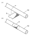
穂先竿1として中実状竿体1Dに高比重物としての高比重板状体9を巻回するものについて説明する。図には示していないが、中実状竿体1Dについては次ぎのように製作する。竿の軸線方向に沿って束ねた炭素繊維等の強化繊維の束を熱硬化性樹脂の液内に潜らせて樹脂を含浸させた後ダイスより引き抜く。引き抜いた棒状体に対して竿尻側程大径化するテーパ状の外周面に研磨加工を施し、研磨加工後所定長さに裁断して、中実状竿体1Dを構成する。
[First Embodiment]
The thing which winds the high specific gravity plate-
一方、高比重板状体9を製作する為に、炭素繊維等より高比重であるタングステン繊維等を導入する。そして、このタングステン繊維をクロスに配向し、その配向したタングステン繊維にエポキシ等の熱硬化性樹脂を含浸させて、高比重板状体9としてのプリプレグシートを形成する。そして、図3(イ)(ロ)に示すように、所定のパターンに裁断した高比重板状体9を前記した中実状竿体1Dの外周面の軸線方向中間位置に巻回する。高比重板状体9としてのプリプレグシートを巻回した中実状竿体1Dに対して後記するトップガイド4及び釣糸ガイド3等を装着し仕上塗装等を施して穂先竿1を構成する点は、中空状竿体と同一である。
On the other hand, in order to manufacture the high specific gravity plate-
〔第2実施形態〕
穂先竿1として中空状竿体内に高比重物としての錘2を収納するものについて説明する。図1及び図2に示すように、炭素繊維等の強化繊維を竿の周方向に引き揃え、引き揃え強化繊維にエポキシ等の熱硬化性樹脂を含浸させたプリプレグシートを所定のパターンに裁断したものを二枚用意する。前記したプリプレグシートと強化繊維の引き揃え方向が異なるもの、つまり、引き揃え方向を竿の軸線方向に設定したプリプレグシートを所定のパターンに裁断したものを、前記した二枚のもので挟み込むようにする。
[Second Embodiment]
A description will be given of a case in which the
前記した3枚のパターンを重ねて、マンドレルに巻回して、焼成後所定長に裁断して中空状竿体1Cを構成する。一方、金属製の錘2を中空状竿体1Cの内部空間1aの内周壁に沿った円錐台状に形成する。この形成した円錐台状の錘2を竿尻開口より内部空間1a内に差込み、錘2を内周壁に接着固定する。これによって、中空状竿体1Cの内部空間1aの軸線方向の一部に、高比重物としての錘2を装着することができる。中空状竿体1Cに対して後記するトップガイド4及び釣糸ガイド3等を装着し仕上塗装等を施して穂先竿1を構成する。
The above three patterns are overlapped, wound around a mandrel, and cut into a predetermined length after firing to form a
ここでは、第2実施形態に係る別形態について説明する。
(1) 錘2としては、高比重であるステンレス等を材料とするのがよいが、これに相当する比重を有するものであればよい。
(2) 穂先竿1に錘11を取り付けるものについて説明する。図6(イ)(ロ)に示すように、プリプレグ製の穂先竿1の略半分の長さの第1中空状竿体10Aと第2中空状竿体10Bを用意し、錘2を両中空状竿体10A、10Bとで挟み込み、第1中空状竿体10A、錘11、第2中空状竿体10Bとを軸線方向に順次連結して穂先竿1を構成する。この場合に、錘11と両中空状竿体10A、10Bとを連結するために、錘11の竿先側と竿尻側とに嵌合用の突出部11A、11Bを形成するとともに、第1中空状竿体10Aの竿尻端、及び、第2中空状竿体10Bの竿先端に、前記突出部11A、11Bを内嵌合する嵌合孔10a、10bを形成する。
このような構成により、突出部11Aを嵌合孔10aに、突出部11Bを嵌合孔10bに嵌合させ接着固定することによって、両中空状竿体10A、10Bの間に錘11を挟み込み固定することができる。接着固定した後には、両中空状竿体10A、10Bと錘11の外周面とが滑らかに繋がるように研磨加工等を施す。
第1、第2中空状竿体10A、10Bの代わりに、中実状竿体を使用してもよい。
(3) 上記実施形態では、錘2を施す対象として、穂先竿1だけについて施す場合を説明したが、二番竿や三番竿等に施してもよい。
Here, another embodiment according to the second embodiment will be described .
(1) The
(2) What attaches the
With this configuration, the
A solid casing may be used instead of the first and second
(3) In the above-described embodiment, the case where the
〔第3実施形態〕
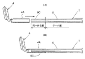
前記した二つの実施形態に加えて、次ぎのような形態を加えたものを説明する。つまり、穂先竿1におけるトップガイド4の取り付け部分の改良について説明すると、図4及び図5に示すように、トップガイド4のボス部4Aの内周面形状に合わせて、穂先竿1の竿先端部の軸線方向一定長さに亘って同一外径の円筒面を形成し、この円筒面部をトップガイド装着部6Cとする。
[Third Embodiment]
In addition to the two embodiments described above, the following embodiment will be described. That is, the improvement of the attachment portion of the
前記したトップガイド装着部6Cの形成方法について説明する。図示していないが、マンドレルの竿先端部に同一外径の円筒面部分を形成するとともに竿尻側に軸線方向に長い緩傾斜テーパ部を形成する。
一方、マンドレルに巻回するプリプレグシートとしてはつぎのようなものを用意する。炭素繊維等の強化繊維を竿の周方向に引き揃え、引き揃え強化繊維にエポキシ等の熱硬化性樹脂を含浸させたプリプレグシートを所定のパターンに裁断したものを二枚用意する。前記したプリプレグシートと強化繊維の引き揃え方向が異なるもの、つまり、引き揃え方向を竿の軸線方向に設定したプリプレグシートを所定のパターンに裁断したものを、前記した二枚のもので挟み込むようにする。
A method for forming the above-described top
On the other hand, as a prepreg sheet wound around a mandrel, the following is prepared. Two sheets are prepared by aligning reinforcing fibers such as carbon fibers in the circumferential direction of the ridge, and cutting a prepreg sheet in which the aligned reinforcing fibers are impregnated with a thermosetting resin such as epoxy into a predetermined pattern. As described above, the prepreg sheet and the reinforcing fiber with different alignment directions, that is, the prepreg sheet with the alignment direction set in the axial direction of the ridge is cut into a predetermined pattern so as to be sandwiched between the two sheets described above. To do.
ここに、パターン形状としては、マンドレルの形状に合わせて、竿の周方向に対応する横幅を一定にした定幅部分と緩傾斜面を備えた緩傾斜部とを備えるように、変形パターンが採用されている。
これら3枚のパターンを重ねてマンドレルに巻回し、中空状竿体6を構成する。中空状竿体6を形成後、その中空状竿体6の竿先端部を同一外径の円筒状部分ができ、トップガイド装着部6Cを形成する。
Here, as the pattern shape, a deformation pattern is adopted so as to have a constant width portion with a constant lateral width corresponding to the circumferential direction of the collar and a gently inclined portion with a gently inclined surface according to the shape of the mandrel. Has been.
These three patterns are overlapped and wound around a mandrel to form a
以上のように、トップガイド装着部6Cの外周面とトップガイド4のボス部4Aの内周面とが同一径の円筒面に形成されているので、トップガイド4をトップガイド装着部6Cに外嵌装着した場合に、隙間なく装着することができる。トップガイド4を装着した中空状竿体6に塗装等を施して穂先竿1を構成する。
As described above, since the outer peripheral surface of the top
〔第4実施形態〕
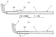
ここでは、第3実施形態で示した中空状竿体6にトップガイド装着部6Cを形成するのに代えて、中実状竿体7にトップガイド装着部7Cを施すことを説明する。前記したように、竿の軸線方向に沿って束ねた炭素繊維等の強化繊維の束を熱硬化性樹脂の液内に潜らせて樹脂を含浸させた後ダイスより引き抜く。引き抜いた棒状体に対して竿尻側程大径化するテーパ状の外周面に研磨加工を施し、研磨加工後所定長さに裁断して、中実状竿体7を構成する。この中実状竿体7の竿先側部分には、トップガイド装着部7Cを形成すべく、外径を一定にした円柱状の同一外径部を研磨して形成する。
[Fourth Embodiment]
Here, instead of forming the top
以上のように、円柱状の同一外径部に形成したトップガイド装着部7Cにトップガイド4を取り付けることによって、トップガイド4のボス部4Aの内周面と円柱状の同一外径部との密着度を高くしてトップガイド4を取り付けることができる。
As described above, by attaching the
〔別実施形態〕
(1) 上記実施形態では、高比重板状体9を施す対象として、穂先竿1だけについて施す場合を説明したが、二番竿や三番竿等に施してもよい。
(2) 第2実施形態においては、高比重板状体9として、タングステンを強化繊維とするプリプレグを採用したが、高比重板状体9として鉄製の輪体を中実状竿体1Dに外嵌固着するようにしてもよい。
[Another embodiment]
(1) In the above-described embodiment, the case where the high specific gravity plate-
(2) In the second embodiment, a prepreg having tungsten as a reinforcing fiber is adopted as the high specific gravity plate-
1 穂先竿
1C、6、10A、10B 中空状竿体
1D 中実状竿体
2、11 錘
3、4 釣糸ガイド
6C、7C トップガイド装着部
9 高比重板状体
1
Claims (3)
Priority Applications (4)
| Application Number | Priority Date | Filing Date | Title |
|---|---|---|---|
| JP2004335830A JP4518554B2 (en) | 2004-11-19 | 2004-11-19 | Fishing rod |
| TW094105070A TW200616537A (en) | 2004-11-19 | 2005-02-21 | Rod body of fishing rod |
| KR1020050022505A KR20060056217A (en) | 2004-11-19 | 2005-03-18 | Rod for fishing rod |
| CN2005100568383A CN1775014B (en) | 2004-11-19 | 2005-03-22 | Rod for fishing rod |
Applications Claiming Priority (1)
| Application Number | Priority Date | Filing Date | Title |
|---|---|---|---|
| JP2004335830A JP4518554B2 (en) | 2004-11-19 | 2004-11-19 | Fishing rod |
Publications (2)
| Publication Number | Publication Date |
|---|---|
| JP2006141284A JP2006141284A (en) | 2006-06-08 |
| JP4518554B2 true JP4518554B2 (en) | 2010-08-04 |
Family
ID=36621648
Family Applications (1)
| Application Number | Title | Priority Date | Filing Date |
|---|---|---|---|
| JP2004335830A Expired - Fee Related JP4518554B2 (en) | 2004-11-19 | 2004-11-19 | Fishing rod |
Country Status (4)
| Country | Link |
|---|---|
| JP (1) | JP4518554B2 (en) |
| KR (1) | KR20060056217A (en) |
| CN (1) | CN1775014B (en) |
| TW (1) | TW200616537A (en) |
Families Citing this family (5)
| Publication number | Priority date | Publication date | Assignee | Title |
|---|---|---|---|---|
| JP2011135778A (en) * | 2009-12-25 | 2011-07-14 | Ever Green International:Kk | Fishing rod, top guide, and sinker |
| JP5997983B2 (en) * | 2012-08-31 | 2016-09-28 | グローブライド株式会社 | fishing rod |
| JP5887250B2 (en) * | 2012-10-30 | 2016-03-16 | グローブライド株式会社 | fishing rod |
| JP5982258B2 (en) * | 2012-10-30 | 2016-08-31 | グローブライド株式会社 | fishing rod |
| JP6441654B2 (en) | 2014-03-26 | 2018-12-19 | グローブライド株式会社 | Throwing and manufacturing method |
Citations (5)
| Publication number | Priority date | Publication date | Assignee | Title |
|---|---|---|---|---|
| JPH04320637A (en) * | 1991-04-19 | 1992-11-11 | Daiwa Seiko Inc | Fishing rod |
| JP2001231408A (en) * | 2000-02-25 | 2001-08-28 | Shimano Inc | Fishing rod |
| JP2002315475A (en) * | 2001-04-20 | 2002-10-29 | Shimano Inc | Top rod |
| JP2002354969A (en) * | 2001-05-30 | 2002-12-10 | Daiwa Seiko Inc | Fishing rod equipped with outer line guides |
| JP2003023925A (en) * | 2001-05-25 | 2003-01-28 | Wc Bradley Zebco Holdings Inc | Damage resistant fishing rod |
Family Cites Families (3)
| Publication number | Priority date | Publication date | Assignee | Title |
|---|---|---|---|---|
| JP4730802B2 (en) * | 2001-09-13 | 2011-07-20 | 株式会社シマノ | Earhead |
| JP3892695B2 (en) * | 2001-10-01 | 2007-03-14 | 株式会社シマノ | fishing rod |
| JP4395446B2 (en) * | 2003-01-24 | 2010-01-06 | 株式会社シマノ | Fishing rods |
-
2004
- 2004-11-19 JP JP2004335830A patent/JP4518554B2/en not_active Expired - Fee Related
-
2005
- 2005-02-21 TW TW094105070A patent/TW200616537A/en not_active IP Right Cessation
- 2005-03-18 KR KR1020050022505A patent/KR20060056217A/en not_active Application Discontinuation
- 2005-03-22 CN CN2005100568383A patent/CN1775014B/en not_active Expired - Fee Related
Patent Citations (5)
| Publication number | Priority date | Publication date | Assignee | Title |
|---|---|---|---|---|
| JPH04320637A (en) * | 1991-04-19 | 1992-11-11 | Daiwa Seiko Inc | Fishing rod |
| JP2001231408A (en) * | 2000-02-25 | 2001-08-28 | Shimano Inc | Fishing rod |
| JP2002315475A (en) * | 2001-04-20 | 2002-10-29 | Shimano Inc | Top rod |
| JP2003023925A (en) * | 2001-05-25 | 2003-01-28 | Wc Bradley Zebco Holdings Inc | Damage resistant fishing rod |
| JP2002354969A (en) * | 2001-05-30 | 2002-12-10 | Daiwa Seiko Inc | Fishing rod equipped with outer line guides |
Also Published As
| Publication number | Publication date |
|---|---|
| TWI331896B (en) | 2010-10-21 |
| KR20060056217A (en) | 2006-05-24 |
| CN1775014B (en) | 2011-06-01 |
| JP2006141284A (en) | 2006-06-08 |
| CN1775014A (en) | 2006-05-24 |
| TW200616537A (en) | 2006-06-01 |
Similar Documents
| Publication | Publication Date | Title |
|---|---|---|
| JP4784968B2 (en) | Fishing rod | |
| CN103841823A (en) | Fishing rod | |
| KR20190038786A (en) | Fishing rod | |
| JP4518554B2 (en) | Fishing rod | |
| JP2000316428A (en) | Guide for fishing rod, fishing rod and its production | |
| JP2007289067A (en) | Spear point rod | |
| JP5982258B2 (en) | fishing rod | |
| JPH0365130A (en) | Fishing rod with replaceable fishing- line guide device, and use of such fishing rod | |
| TWI803819B (en) | Reel seat for fishing rod, grip member for fishing rod, and fishing rod | |
| JP2009060916A (en) | Method for producing fishing rod tip | |
| JP5570178B2 (en) | fishing rod | |
| JP4641888B2 (en) | Earhead | |
| EP2926651B1 (en) | Casting rod and method of fabricating tip rod of casting rod | |
| JP4328656B2 (en) | Tip for fishing rod | |
| JP2007330118A (en) | Rod body of fishing rod | |
| JP4022124B2 (en) | fishing rod | |
| JP2005040075A (en) | Fishing rod | |
| JP6131314B2 (en) | fishing rod | |
| JP2007020406A (en) | Ear tip rod | |
| JP4420367B2 (en) | Manufacturing method of housing | |
| JP4618711B2 (en) | Telescopic fishing rod | |
| JP4514348B2 (en) | Top guide | |
| JP4539953B2 (en) | An inlay splice type fishing rod and a method of manufacturing an inlay core constituting the same. | |
| JP5517512B2 (en) | fishing rod | |
| JP2009095303A (en) | Rod body for fishing rod and fishing rod |
Legal Events
| Date | Code | Title | Description |
|---|---|---|---|
| A621 | Written request for application examination |
Free format text: JAPANESE INTERMEDIATE CODE: A621 Effective date: 20071025 |
|
| RD04 | Notification of resignation of power of attorney |
Free format text: JAPANESE INTERMEDIATE CODE: A7424 Effective date: 20090827 |
|
| A977 | Report on retrieval |
Free format text: JAPANESE INTERMEDIATE CODE: A971007 Effective date: 20090916 |
|
| RD02 | Notification of acceptance of power of attorney |
Free format text: JAPANESE INTERMEDIATE CODE: A7422 Effective date: 20090916 |
|
| A131 | Notification of reasons for refusal |
Free format text: JAPANESE INTERMEDIATE CODE: A131 Effective date: 20091007 |
|
| A521 | Request for written amendment filed |
Free format text: JAPANESE INTERMEDIATE CODE: A523 Effective date: 20091118 |
|
| TRDD | Decision of grant or rejection written | ||
| A01 | Written decision to grant a patent or to grant a registration (utility model) |
Free format text: JAPANESE INTERMEDIATE CODE: A01 Effective date: 20100517 |
|
| A01 | Written decision to grant a patent or to grant a registration (utility model) |
Free format text: JAPANESE INTERMEDIATE CODE: A01 |
|
| A61 | First payment of annual fees (during grant procedure) |
Free format text: JAPANESE INTERMEDIATE CODE: A61 Effective date: 20100517 |
|
| FPAY | Renewal fee payment (event date is renewal date of database) |
Free format text: PAYMENT UNTIL: 20130528 Year of fee payment: 3 |
|
| R150 | Certificate of patent or registration of utility model |
Ref document number: 4518554 Country of ref document: JP Free format text: JAPANESE INTERMEDIATE CODE: R150 Free format text: JAPANESE INTERMEDIATE CODE: R150 |
|
| FPAY | Renewal fee payment (event date is renewal date of database) |
Free format text: PAYMENT UNTIL: 20140528 Year of fee payment: 4 |
|
| R250 | Receipt of annual fees |
Free format text: JAPANESE INTERMEDIATE CODE: R250 |
|
| R250 | Receipt of annual fees |
Free format text: JAPANESE INTERMEDIATE CODE: R250 |
|
| R250 | Receipt of annual fees |
Free format text: JAPANESE INTERMEDIATE CODE: R250 |
|
| R250 | Receipt of annual fees |
Free format text: JAPANESE INTERMEDIATE CODE: R250 |
|
| R250 | Receipt of annual fees |
Free format text: JAPANESE INTERMEDIATE CODE: R250 |
|
| R250 | Receipt of annual fees |
Free format text: JAPANESE INTERMEDIATE CODE: R250 |
|
| R250 | Receipt of annual fees |
Free format text: JAPANESE INTERMEDIATE CODE: R250 |
|
| R250 | Receipt of annual fees |
Free format text: JAPANESE INTERMEDIATE CODE: R250 |
|
| R250 | Receipt of annual fees |
Free format text: JAPANESE INTERMEDIATE CODE: R250 |
|
| R250 | Receipt of annual fees |
Free format text: JAPANESE INTERMEDIATE CODE: R250 |
|
| LAPS | Cancellation because of no payment of annual fees |


