JP4512858B2 - Two-sheet balance plate for gerotor motor - Google Patents
Two-sheet balance plate for gerotor motor Download PDFInfo
- Publication number
- JP4512858B2 JP4512858B2 JP2000029166A JP2000029166A JP4512858B2 JP 4512858 B2 JP4512858 B2 JP 4512858B2 JP 2000029166 A JP2000029166 A JP 2000029166A JP 2000029166 A JP2000029166 A JP 2000029166A JP 4512858 B2 JP4512858 B2 JP 4512858B2
- Authority
- JP
- Japan
- Prior art keywords
- fluid
- balance plate
- star
- fluid pressure
- disposed
- Prior art date
- Legal status (The legal status is an assumption and is not a legal conclusion. Google has not performed a legal analysis and makes no representation as to the accuracy of the status listed.)
- Expired - Lifetime
Links
Images


Classifications
-
- F—MECHANICAL ENGINEERING; LIGHTING; HEATING; WEAPONS; BLASTING
- F01—MACHINES OR ENGINES IN GENERAL; ENGINE PLANTS IN GENERAL; STEAM ENGINES
- F01C—ROTARY-PISTON OR OSCILLATING-PISTON MACHINES OR ENGINES
- F01C21/00—Component parts, details or accessories not provided for in groups F01C1/00 - F01C20/00
- F01C21/18—Arrangements for admission or discharge of the working fluid, e.g. constructional features of the inlet or outlet
-
- F—MECHANICAL ENGINEERING; LIGHTING; HEATING; WEAPONS; BLASTING
- F01—MACHINES OR ENGINES IN GENERAL; ENGINE PLANTS IN GENERAL; STEAM ENGINES
- F01C—ROTARY-PISTON OR OSCILLATING-PISTON MACHINES OR ENGINES
- F01C1/00—Rotary-piston machines or engines
- F01C1/08—Rotary-piston machines or engines of intermeshing engagement type, i.e. with engagement of co- operating members similar to that of toothed gearing
- F01C1/082—Details specially related to intermeshing engagement type machines or engines
- F01C1/088—Elements in the toothed wheels or the carter for relieving the pressure of fluid imprisoned in the zones of engagement
-
- F—MECHANICAL ENGINEERING; LIGHTING; HEATING; WEAPONS; BLASTING
- F01—MACHINES OR ENGINES IN GENERAL; ENGINE PLANTS IN GENERAL; STEAM ENGINES
- F01C—ROTARY-PISTON OR OSCILLATING-PISTON MACHINES OR ENGINES
- F01C1/00—Rotary-piston machines or engines
- F01C1/08—Rotary-piston machines or engines of intermeshing engagement type, i.e. with engagement of co- operating members similar to that of toothed gearing
- F01C1/10—Rotary-piston machines or engines of intermeshing engagement type, i.e. with engagement of co- operating members similar to that of toothed gearing of internal-axis type with the outer member having more teeth or tooth-equivalents, e.g. rollers, than the inner member
- F01C1/104—Rotary-piston machines or engines of intermeshing engagement type, i.e. with engagement of co- operating members similar to that of toothed gearing of internal-axis type with the outer member having more teeth or tooth-equivalents, e.g. rollers, than the inner member one member having simultaneously a rotational movement about its own axis and an orbital movement
- F01C1/105—Rotary-piston machines or engines of intermeshing engagement type, i.e. with engagement of co- operating members similar to that of toothed gearing of internal-axis type with the outer member having more teeth or tooth-equivalents, e.g. rollers, than the inner member one member having simultaneously a rotational movement about its own axis and an orbital movement and having an articulated driving shaft
-
- F—MECHANICAL ENGINEERING; LIGHTING; HEATING; WEAPONS; BLASTING
- F01—MACHINES OR ENGINES IN GENERAL; ENGINE PLANTS IN GENERAL; STEAM ENGINES
- F01C—ROTARY-PISTON OR OSCILLATING-PISTON MACHINES OR ENGINES
- F01C19/00—Sealing arrangements in rotary-piston machines or engines
- F01C19/08—Axially-movable sealings for working fluids
- F01C19/085—Elements specially adapted for sealing of the lateral faces of intermeshing-engagement type machines or engines, e.g. gear machines or engines
-
- F—MECHANICAL ENGINEERING; LIGHTING; HEATING; WEAPONS; BLASTING
- F01—MACHINES OR ENGINES IN GENERAL; ENGINE PLANTS IN GENERAL; STEAM ENGINES
- F01C—ROTARY-PISTON OR OSCILLATING-PISTON MACHINES OR ENGINES
- F01C21/00—Component parts, details or accessories not provided for in groups F01C1/00 - F01C20/00
- F01C21/003—Systems for the equilibration of forces acting on the elements of the machine
-
- F—MECHANICAL ENGINEERING; LIGHTING; HEATING; WEAPONS; BLASTING
- F01—MACHINES OR ENGINES IN GENERAL; ENGINE PLANTS IN GENERAL; STEAM ENGINES
- F01C—ROTARY-PISTON OR OSCILLATING-PISTON MACHINES OR ENGINES
- F01C21/00—Component parts, details or accessories not provided for in groups F01C1/00 - F01C20/00
- F01C21/04—Lubrication
-
- F—MECHANICAL ENGINEERING; LIGHTING; HEATING; WEAPONS; BLASTING
- F03—MACHINES OR ENGINES FOR LIQUIDS; WIND, SPRING, OR WEIGHT MOTORS; PRODUCING MECHANICAL POWER OR A REACTIVE PROPULSIVE THRUST, NOT OTHERWISE PROVIDED FOR
- F03C—POSITIVE-DISPLACEMENT ENGINES DRIVEN BY LIQUIDS
- F03C2/00—Rotary-piston engines
- F03C2/08—Rotary-piston engines of intermeshing-engagement type, i.e. with engagement of co- operating members similar to that of toothed gearing
-
- F—MECHANICAL ENGINEERING; LIGHTING; HEATING; WEAPONS; BLASTING
- F04—POSITIVE - DISPLACEMENT MACHINES FOR LIQUIDS; PUMPS FOR LIQUIDS OR ELASTIC FLUIDS
- F04C—ROTARY-PISTON, OR OSCILLATING-PISTON, POSITIVE-DISPLACEMENT MACHINES FOR LIQUIDS; ROTARY-PISTON, OR OSCILLATING-PISTON, POSITIVE-DISPLACEMENT PUMPS
- F04C15/00—Component parts, details or accessories of machines, pumps or pumping installations, not provided for in groups F04C2/00 - F04C14/00
- F04C15/0003—Sealing arrangements in rotary-piston machines or pumps
- F04C15/0023—Axial sealings for working fluid
- F04C15/0026—Elements specially adapted for sealing of the lateral faces of intermeshing-engagement type machines or pumps, e.g. gear machines or pumps
-
- F—MECHANICAL ENGINEERING; LIGHTING; HEATING; WEAPONS; BLASTING
- F04—POSITIVE - DISPLACEMENT MACHINES FOR LIQUIDS; PUMPS FOR LIQUIDS OR ELASTIC FLUIDS
- F04C—ROTARY-PISTON, OR OSCILLATING-PISTON, POSITIVE-DISPLACEMENT MACHINES FOR LIQUIDS; ROTARY-PISTON, OR OSCILLATING-PISTON, POSITIVE-DISPLACEMENT PUMPS
- F04C15/00—Component parts, details or accessories of machines, pumps or pumping installations, not provided for in groups F04C2/00 - F04C14/00
- F04C15/0042—Systems for the equilibration of forces acting on the machines or pump
-
- F—MECHANICAL ENGINEERING; LIGHTING; HEATING; WEAPONS; BLASTING
- F04—POSITIVE - DISPLACEMENT MACHINES FOR LIQUIDS; PUMPS FOR LIQUIDS OR ELASTIC FLUIDS
- F04C—ROTARY-PISTON, OR OSCILLATING-PISTON, POSITIVE-DISPLACEMENT MACHINES FOR LIQUIDS; ROTARY-PISTON, OR OSCILLATING-PISTON, POSITIVE-DISPLACEMENT PUMPS
- F04C15/00—Component parts, details or accessories of machines, pumps or pumping installations, not provided for in groups F04C2/00 - F04C14/00
- F04C15/0088—Lubrication
Landscapes
- Engineering & Computer Science (AREA)
- Mechanical Engineering (AREA)
- General Engineering & Computer Science (AREA)
- Chemical & Material Sciences (AREA)
- Combustion & Propulsion (AREA)
- Physics & Mathematics (AREA)
- Fluid Mechanics (AREA)
- Hydraulic Motors (AREA)
- Rotary Pumps (AREA)
Description
【0001】
【発明の属する技術分野】
本発明は、回転流体圧装置、特にジェロータディスプレースメント機構を含む上記装置に関する。
【0002】
【従来の技術】
本発明は、流体ポンプとして使用することができるジェロータ装置とともに使用するとよいが、ジェロータモータの一部として使用すると特に好適であり、これに関連して、とりわけ低速高トルクタイプのものについても以下で説明する。さらに、本発明は、相対的に高圧および高トルクで作動するように構成されるジェロータ装置の一部として使用すると特に好適である。
【0003】
さらに、本発明は、各種タイプの弁装置(valving)を有するジェロータモータとともに使用するのに適しているが、特に「バルブ・イン・スター」(VIS)タイプの高圧モータにおいて使用すると好適であり、これに関連して以下で説明する。VISモータの一例は、本発明の譲受人に譲渡された米国特許第4,741,681号に記載されており、この特許は参照として本明細書中に含まれる。VISモータでは、整流弁作用は、軌道回転運動しているジェロータ星形部材と、一般的にモータハウジング(または端部キャップ)の一部であるか、あるいは別部材からなるものであるが、モータハウジングに対して回転自在に固定されている隣接の固定弁プレートとの間の界面で得られる。上記固定弁がモータハウジングと別部材であるVISモータの一例が、同様に本発明の譲受人に譲渡された米国特許第4,976,594号に記載されており、この特許は参照として本明細書中に含まれる。
【0004】
本発明が関連する種類の低速高トルクのジェロータモータは、高背圧、すなわち、モータの戻り(出口)ポートにおいて格納室圧力を実質的に上回る圧力の存在下であっても良好に実行可能であることが期待されている。当業者には周知であるように、背圧が高いことは、システムチャージ圧力が上昇し続けることで水圧推進ポンプ(hydrostatic propel pump)のディスプレースメントを制御するサーボシステムの性能を改善する閉回路車両推進システムの場合には一般的である。同様に周知であるように、システムチャージ圧力は、本来、モータにおける背圧を決定する。チャージ圧力(「メイクアップ(make-up)」流体)は、推進モータの出口側である該システムの低圧側と連通される。
【0005】
VISタイプのモータの固有の特性は、背圧によりジェロータ星形部材に分離力が働くと、星形部材(軌道回転運動している弁部材)を固定弁部材にある隣接する弁装置面と分離させる傾向がある。ジェロータモータ技術に精通している者には周知であるように、隣接する弁装置面をこのように分離させると、モータの容積効率は実質的に低下する。容積効率は、モータの実際の出力と、モータ内部に漏れがなかった場合に生じるモータの原理上の出力との比である。システム圧力を使用することでジェロータ星形部材が固定弁部材の隣接面方向に付勢されるので、所定のVISモータ構成にとって、星形部材の分離問題は、システム圧力の上昇時の問題ほどではない。むしろ、システム圧力が相対的に小さくなったときに結果として星形部材にかかる付勢力が弱くなってしまう場合が重大視されることもある。この問題は、モータが比較的高圧用途に意図されるという事実に鑑みて使用される比較的高いボルトトルクにより悪化するおそれがあることが信じられている。高ボルトトルクは、従来技術のバランシングプレートを歪めることで、ジェロータとバランシングプレートの間に漏出隙間を開け、容積効率を低下させるという影響を及ぼす可能性がある。より懸念されることは、実際に望ましいことが既知の予測可能な予荷重であるにもかかわらず、このボルトトルクにより、ねじ仕上げ等の要素のばらつきという観点から予測不能な予荷重がバランシングプレートにかかることになる。
【0006】
【発明が解決しようとする課題】
したがって、本発明の目的は、改良型低速高トルクのジェロータモータ、特に、容積効率の低下を少なくした、比較的高背圧の存在下であっても首尾よく実行可能なVISタイプのモータを提供することである。
【0007】
本発明の他の目的はジェロータの側面隙間を減少して容積効率を向上させることを可能としつつ、側面隙間の公差を効率よく広げることでジェロータの製造コストを低下させる、改良型バランシングプレートおよびシール構造を有するVISタイプのジェロータモータを提供することである。
【0008】
ジェロータの側面隙間を減少して容積効率を向上させる努力は、1つの望ましくない影響を及ぼし得ることが観察されている。星形部材の前面(すなわち、固定弁プレートに対向する端部)に隣接して配置されたバランシングプレートにかかる荷重が増大した結果、星形歯の端面とバランシングプレートの隣接面の間、特に隣接面間の相対速度が高速である場所に擦傷が生じる可能性がある。ジェロータモータ技術に精通した者には周知のように、相対移動している部分が擦り合わされると、モータの全体操作性が非常に早く不良になりやすい。
【0009】
したがって、本発明の他の目的は、ジェロータ星形部材の端面とバランシングプレートの隣接面との擦り合いを防止する性能を強化した改良型ジェロータモータを提供することである。
【0010】
本発明のさらに他の目的は、擦り剥けた部位に加圧流体を流すことによって上述の目的を達成し、これにより擦り剥ける可能性のある部位を冷却して潤滑させた改良型ジェロータモータを提供することである。
【0011】
【課題を解決するための手段】
本発明の上記および他の目的は、流体入口ポートおよび流体出口ポートを形成するハウジング手段を備えた回転流体圧装置を提供することによって達成される。流体圧ディスプレースメント機構は、ハウジング手段と組み合わされ、内歯付きリング部材および該リング部材内に偏心配置された外歯付き星形部材を備えている。リング部材および星形部材は、軌道回転運動し、相互係合することによってこの軌道回転運動に応じて膨張および収縮流体容積チャンバを形成する。弁手段はハウジング手段と協働して、流体入口ポートと膨張容積チャンバとの間、および収縮容積チャンバと流体出口ポートとの間を流体連通させる。ハウジング手段は、リング部材の後方に配置された、弁手段の一部を含む端部キャップアセンブリと、リング部材の前方に配置されたハウジング部材とを備えている。ファスナ孔には、複数のファスナが配設され、このファスナは、端部キャップアセンブリとハウジング部材をリング部材に対して密封シール係合状態に維持している。リング部材とハウジング部材との間には、バランシングプレートが配置され、星形部材の隣接端面に密接させることによってその間の流体漏れを最小限に抑えることができるようにしている。
【0012】
改良型の回転流体圧装置は、バランシングプレートが、外側バランスプレートと内側バランスプレートを有するバランシングプレートアセンブリを備えることを特徴とする。外側バランスプレートには、流体容積チャンバから半径方向内側に配置される内側プロフィールが形成される。内側バランスプレートは、これと組み合わされ、星形部材との係合方向に内側バランスプレートを付勢する手段を有する。
【0013】
本発明の別の態様によれば、改良型の回転流体圧装置は、星形部材の隣接端面には流体チャンバが形成され、星形部材には、流体ディスプレースメント機構の上流にある主流体流動経路から流体チャンバに加圧流体を連通させて固定弁部材方向に星形部材の流体圧を付勢する流体通路が形成されるタイプのものである。
【0014】
本発明の別の態様によれば、改良型の回転流体圧装置は、星形部材の隣接端面が複数の独立した星形歯面を備えることを特徴とする。星形歯面のそれぞれには、流体チャンバと連通した略半径方向に延在する流体通路が形成される。さらに、星形歯面のそれぞれには、流体通路が半径方向の流体通路と略垂直に配向されており、該半径方向流体通路から離れていくにつれて流量を減少させ、これによりバランシングプレートと星形部材の隣接端面との間に加圧流体をもたらす。
【0015】
【発明の実施の形態】
次に、図面を参照しながら説明するが、これらは本発明を限定するものではなく、図1は、上記の特許にしたがって作製されたVISモータを示す。より詳細には、図1に示すVISモータは、単なる例示として、「湿式ボルト(wet-bolt)」設計、ここでボルトはシステム圧力を表す、または「湿潤式ボルト(damp-bolt)」設計、ここでボルトはケース圧力を表す、のいずれか一方である。いずれの場合においても、該モータは、同様に本発明の譲受人に譲渡された米国特許第5,211,551号(参照として本明細書中に組み込む)の開示にしたがって作製できる。
【0016】
図1に示すVISモータは、複数の部分を複数のボルト11等で互いに固着して構成されており、図1および図3にはそのうちの1つのみをそれぞれ示すが、図4には全部を示す。モータは、端部キャップ13と、固定弁部材15と、まとめて17で示したジェロータ歯車組と、まとめて19で示したバランシングプレートアセンブリと、フランジ部材21とを備えている。
【0017】
同様に図4に示すジェロータ歯車組17は、当該技術において周知であって、上記の特許にさらに詳細が説明されているため、ここでは概略的な説明にとどめる。歯車組17は、各開口部に円筒形ローラ部材25を配置した複数の略半円筒形開口部を形成する内歯付きリング部材23を、リング部材23の内歯として備えたジェローラ(Geroler)[登録商標]歯車組であることが好ましい。このリング部材23内には、一般的に内歯25の数より1つ少ない外歯を設けた外歯付き星形部材27が偏心配置されており、このため星形部材27がリング部材23に対して軌道回転運動できるようになっている。星形部材27がリング部材23内で軌道回転運動することにより、複数の膨張および収縮流体容積チャンバ29が形成される。
【0018】
依然として主に図1を参照しながら説明すると、星形部材27には、複数の直線状の内側スプライン30(図1、図7および図8参照)が形成され、これらが主駆動軸33(図1に一部のみ示す)の一端に形成された1組の冠状の外側スプライン31と係合している。主駆動軸33の他端には、1組の冠状の外側スプライン(図示せず)が別に設けられ、軸またはホイールハブ(図示せず)等の何らかの形式の回転出力部材により形成された別組の直線状の内側スプラインと係合するようになっている。当業者には周知のように、図示の一般的なタイプのジェロータモータには、適当な軸受で支持される回転出力軸をさらに追加して設けてもよい。
【0019】
次に、図1とともに主に図2を参照しながら、星形部材27をさらに詳細に説明していく。本発明の本質的な特徴ではないが、星形部材27は2個の別パーツの組み付けで構成されることが好ましい。本実施形態において、星形部材27は、外歯を備えた主星形部分37と、インサート部またはプラグ39とを含む2個の別パーツを備えている。主部分37とインサート部39との協働により、以下に説明する各種流体ゾーン、通路およびポートが形成される。星形部材27は、星形部材27の端面43に中央マニホルドゾーン41が形成され、端面43は、固定弁部材15の隣接面45(図3を参照)と摺動可能なシール係合状態に配置されている。
【0020】
星形部材27の端面43には1組の流体ポート47が形成され、それぞれ、インサート部39に形成された流体通路49(流体通路49の1つのみを図2に示す)によりマニホルドゾーン41と連続的に流体連通している。さらに、端面43には、1組の流体ポート51が流体ポート47と交互に配置され、各流体ポート51には、部分53がインサート部39により形成され、マニホルドゾーン41との半径方向ほぼ中間位置まで半径方向内側に延在している。
【0021】
次に、図1とともに主に図3を参照しながら、端部キャップ13および固定弁部材15をさらに詳細に説明していく。上記米国特許第5,211,551号に記載されているように、本実施形態のように端部キャップおよび固定弁部材を別部材として形成することは周知であり、これらを「端部キャップアセンブリ」と呼ぶこともできる。あるいは、端部キャップと固定弁とで単一の一体パーツを構成してもよく、この場合、「固定弁手段」または他の同様な用語についての言及は、ジェロータ歯車組に直に隣接して配置される端部キャップの部分を示していることが理解されよう。本発明が上述のいずれの構造を使用し得ることが理解されるはずである。
【0022】
端部キャップ13には、流体入口ポート55が設けられ、入口ポート55と開放連続流体連通した環状チャンバ59がさらに形成される。端部キャップ13および固定弁部材15の協働により円筒形チャンバ61が形成され、本明細書の目的において、この円筒形チャンバ61は、出口ポートと非制限流体連通し、かつ星形部材27の軌道回転とともにマニホルドゾーン41と非制限流体連通することが一般的であることから出口ポートの一部と考えることができよう。円筒形チャンバ61の周囲には、全体を63で付された流体圧領域(図3を参照)が設けられ、該領域は、それぞれ通路67(図1を参照)によって環状チャンバ59と連続流体連通している複数の独立した固定圧力ポート65を含む。
【0023】
さらに固定弁部材15には、当該技術分野では「タイミングスロット」ともいわれる複数の固定弁通路69が形成されている。本実施形態において、弁通路69は、それぞれ、半径方向に配向されたスロットを一般に備え、各スロットは、隣接する容積チャンバ29と開放連続流体連通状態にそれぞれ配置されている。弁通路69は、図3に示されるように、流体圧領域63に対して同心の略環状パターンで配置されることが好ましい。本実施形態において、および単なる例示として、弁通路69それぞれは、拡大部71に開放している。各ボルト11は、拡大部71をそれぞれ挿通しているが、図3に示されるように、ボルト11が存在していても、流体は拡大部71それぞれの半径方向内側部分を通って容積チャンバ29間を依然として流体連通することができる。
【0024】
再び、主に図1を参照して、従来技術のバランシングプレートの全般的機能を説明していく。上記の米国特許第4,976,594号に開示されているように、システム圧力(高圧)は、バランシングプレートの前側(すなわち、フランジ部材21に隣接する側)に連通している。いずれの動作方向においても、バランシングプレートは、星形部材27の方向に付勢される。換言すれば、星形部材27の1回の軌道回転を通して、正味力はバランシングプレートを星形部材の方向に付勢している。しかしながら、星形部材の僅かなチッピング(tipping)ないしコッキング(cocking)、またはボルトトルクが不均一に分布する等の様々な理由から、バランシングプレートを星形部材27から僅かに分離する部位が局所的に存在し得る。
【0025】
動作中、高圧流体は入口ポート55と連通され、そこから環状チャンバ59に流れ、続いて個別通路67を通って圧力ポート65に流入する。星形部材27の軌道回転とともに、9個の圧力ポート65は、星形部材27に設けられた流体ポート51の8個の半径方向内側部分53と整流流体連通状態で係合する。このため、高圧流体は、弁通路69の1つと流体連通しているか、まもなく上記の流体連通を行うか、あるいは上記の流体連通を完了直後の流体ポート51のみと連通していく。
【0026】
高圧流体は、偏心線の膨張容積チャンバと同一側にある流体ポート51のみと連通され、次いで高圧流体は、これらの特定流体ポート51から固定弁通路69および拡大部71をそれぞれ通って膨張容積チャンバ29に流入する。
【0027】
収縮容積チャンバ29から流出する低圧排出流体は、拡大部71および弁通路69をそれぞれ通って、星形部材27に設けられた流体ポート47に流入する。この低圧流体は、次に半径方向流体通路49と連通してマニホルドゾーン41に流入し、そこから低圧流体は円筒形チャンバ61を通り、対応する出口ポートに達する。以上で説明した主流路全体は一般に当該技術分野において周知であることが、当業者に理解されるであろう。上述の発明の詳細な説明の項で説明したように、出口ポート61では、通常の背圧より略高圧であり、その結果、星形部材27には別途大きな力が作用する。本実施形態において、このように背圧が増大することにより、マニホールドゾーン41の横断面積全体にわたって大きな付勢力がかかることになる。
【0028】
次に、主に図1および図4〜図7を参照して、本発明の重大な一態様を構成するバランスプレートアセンブリ19を詳細に説明する。アセンブリ19は、外側バランスプレート73と内側バランスプレート75とで構成される。本明細書において使用される「外側」および「内側」という用語は、プレート73および75の半径方向の関係を単に示しているにすぎず、すなわち、プレート73とプレート75は、互いに対してそれぞれ半径方向外側と半径方向内側に配置されている。バランスプレート73および75の関係を説明する別の方法では、内側プレート75が外側プレート73に対して「入れ子」状態である。
【0029】
本発明のさらに他の態様において、外側バランスプレート73には、内側プロフィール77(図5を参照)が設けられ、内側バランスプレート75には、外側プロフィール79(図4および図6)が設けられている。本発明の本質的な特徴ではないが、内側プロフィール77および外側プロフィール79は、妥当な製造公差内で互いに比較的密接に配置されていることが好ましく、その間に干渉は全くないがその間の半径方向隙間が最小限に抑えられ、好ましくは、その略全周範囲を越えて最小限に抑えられるように構成される。たとえば、本実施形態において、半径方向隙間は、約0.20インチ(0.50mm)の範囲に維持されている。したがって、図4において「79」と付された線は、外側プレート73の内側プロフィール77も表しているといえる。
【0030】
好ましくは、各プロフィール77および79は、これらのプロフィールの一方または両方が単なる円形としてしまうと内側バランスプレート75が星形部材27の軌道回転とともに自在に回転してしまうことがあるため、非円形である。この結果、相当な摩擦が生じるとともに発熱し、プロフィールが摩耗する可能性がある。本実施形態において、および単なる例示として、プロフィール77および79は、それぞれ9「辺」からなる多角形であり、これにより容積チャンバ29の数およびローラ部材25の数と等しい。
【0031】
本発明の別の重要な一態様において、内側バランスプレート75の外側プロフィール79は、図4に示すように、容積チャンバ29に相対して配置されている。すなわち、星形部材27のいずれの所与の軌道回転位置においても、星形部材27の端面81と外側バランスプレート73の隣接面との間には少なくとも多少の(半径方向において)シーリングランドが設けられている。本発明の当該実施形態において、これは、星形部材の谷部に点を固定し、星形部材を9回旋回(すなわち、1回フル回転)することによって達成された。この結果、このようにして形成されたプロフィールは、プロフィール77および79と全く同一形状であったが、いくらか大きかった。次に、単なる例示として、シーリングランドは0.090インチ(2.2mm)未満であることは決して望ましくないため、生成されたプロフィールを0.090インチだけ半径方向に縮小してプロフィール77および79を生成した。上述したプロフィールおよびその生成方法は本発明の本質部分ではないが本明細書において好適であったことが理解されるはずである。
【0032】
すでに記載したように、外側バランスプレート73の内側プロフィール77は、内側バランスプレート75の外側プロフィール79と狭い間隔で配置されている。したがって、図4において見ることのできる、外側プロフィール79の半径方向外側の端面81は、すべて、端面81と外側バランスプレート73の間の瞬間的シーリングランドを表している。言い換えれば、外側バランスプレート73は、外側プロフィール79の半径方向外側である、ジェロータ歯車組17の略全面積(図4に見られる)を覆っている。
【0033】
次に、主に図7を参照して、本発明の別の重要な一態様を説明していく。図7において最もよくわかるように、外側バランスプレート73は比較的薄いが、内側バランスプレート75は比較的厚い。本明細書を読み理解することで、当業者の技能において、特定のモータ設計に適するようにプレート73および75の厚さを選ぶことができるものと確信する。フランジ部材21には環状チャンバ83が設けられ、その中には、外側バランスプレート73の半径方向内周、すなわち、星形部材の端面81からシールする部分が配置されている。また、環状チャンバ83には、内側バランスプレート75も配置されている。当該技術においてすでに知られているように、システム圧力は、プロフィール77と79の間の隙間を通ってチャンバ83へと連通され、システム圧力により、バランスプレート73および75が星形部材の隣接端面81とのシーリング係合方向に付勢される。また、環状チャンバ83には、内側バランスプレート75の前方にシールリングアセンブリ85も設けられており、チャンバ83内でシステム圧力をシールして、それがシャフト33を取り巻くケースドレン領域に漏れないように機能している。
【0034】
シールリングアセンブリ85の半径方向外側には、皿バネ87が設けられている。ばね87は、その外周がチャンバ83の前壁に当接して着座され、一方内周は、内側バランスプレート75の前面に当接して着座され、プレート75を後方に付勢して星形部材の端面81と係合するように構成されている。したがって、本発明の重要な特徴として、バランシングプレートアセンブリ19は、2枚の別体のバランスプレート73および75を備えている。外側バランスプレート73は、薄めになっているため、星形部材27の隣接端面81に加えてリング部材23の隣接端面とも適応して、効率よくシールすることができる。同時に、内側バランスプレート75は厚めになっており、ボルトトルクから独立してシステム圧力により付勢されている(外側バランスプレート73と同様に)が、皿バネ87によっても機械的に付勢されている。この結果、側面隙間は縮小され、容積効率がさらに向上し、加えて側面隙間許容帯を効果的に広げることで、ジェロータ歯車組の製造を簡略化するとともにそのコストを低下させることができる。
【0035】
次に、主に図1および図8〜図10を参照して、本発明の別の、だが非常に関連のある一態様をいくらか詳細に説明していく。なお、図8は、図4と同一方向から見た図であるが、図示の簡略のため図4では、図8に示した端面81の特徴については図示しなかった。上述の発明の詳細な説明の項で説明したように、星形部材27の端面81と外側バランスプレート73の隣接面との間の側面隙間を縮小し、バランスプレート73にかかる付勢圧力を増大させた結果、擦傷が生じ得るが、図8〜図10に示した特徴が、上記擦傷を実質的になくす上で効果的であることがわかった。
【0036】
上記の米国特許第4,976,594号に開示されているように、星形部材27の端面81には、環状凹部または溝部91が形成され、システム圧力(高圧)を含む47と51のいずれかのポートからの加圧流体を一対の軸方向流体通路93によって収容する。溝部91から、システム圧力は環状チャンバ83へと導通する。各通路91には、チェックボール95が設けられており、溝部91から低圧力を含むポート47または51のいずれかへの流体連通を防止するように機能している。
【0037】
星形部材27の端面81は、以下の説明および添付の特許請求の範囲において、個別星形歯面97を複数個備え、それぞれの面97は、溝部91から半径方向外側の部位を構成し、隣接する星形部材の「谷」間に周方向に配置されている。ここでの「谷」とは当該技術においてよく理解されるものである。各星形歯面97には、半径方向に延在する流体通路99が形成され、溝部91における流体圧と開放連通している。また、各星形歯面97には、流体通路101も半径方向に延在する流体通路99と略垂直に配向されている。より重要なこととして、各流体通路101は、通常星形歯の線形運動の方向、より厳密には、星形部材の瞬間的回転運動と垂直方向に延在する。ジェロータ技術に精通している者にとって周知であるように、星形部材が軌道回転すると、1つの外歯の点を中心にして実際に回動し、回動点から直径方向に配設された歯の端面では、最大線形速度が生じ続ける。各流体通路101は、擦り剥きが非常に発生しやすいような線に沿っているため、その最大速度の線に沿って延設することが好ましい。本実施形態において、モータは双方向であることが好ましいため、流体通路101のうち2つが、各半径方向の流体通路99から延設してこれと流体連通している。
【0038】
好ましい実施形態において、流体通路101は、それぞれ、流体の流動方向、すなわち、半径方向に延在する流体通路99から離れていくにつれて流量を減少させていく。星形歯面97が、外側バランスプレート73の隣接面とシーリング係合状態にあることは記憶されているはずである。したがって、流体が半径方向通路99から流出して流体通路101を通っていくにつれて減少する流量が「ノズル」として作用し、通路101から星形歯面97と外側バランスプレート73の隣接面との間の側面隙間に流入する流体の流体圧の局所化が効果的に増大される。このように通路101を流出した流体は、液圧リフト効果を形成し、擦り剥きが通常発生すると思われる部位における軸受け膜を改良し、また、流体の流動により、その領域の冷却も行うため、擦傷が発生する傾向をさらに減少させる。
【0039】
理論上、通路99および101は、星形部材28またはバランスプレート73のいずれに設けてもよいが、バランスプレート73が比較的薄く、通常はスタンピング等のプロセスによって形成されることから、通路99および101が星形部材の端面81に形成するとよい。
【0040】
本明細書を読み理解することで、当業者の技能において、各種溝部および通路の寸法を選んで本発明の上記目的を達成する、すなわち、容積効率を不当に損失することなく擦傷を実質的に減少させることができるものと確信する。
【0041】
上記明細書において本発明をかなり詳細に説明してきたが、本明細書を読み理解することで、本発明の各種改変および変形が当業者に明らかとなるものと確信する。かかる改変および変形は、添付の特許請求の範囲に含まれる限り、すべて本発明に包含されるものとする。
【図面の簡単な説明】
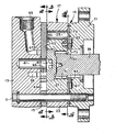
【図1】図1は、本発明に係る低速高トルクのVISジェロータモータを示す軸方向断面図である。
【図2】図2は、図1の線2−2における、星形部材のみを示した横断面図である。
【図3】図3は、図1の線3−3における、図1に比べて寸法を僅かに縮小し、かつ図1に示した位置からいくらか回転させた横断面図である
【図4】図4は、図1の線4−4における、僅かに寸法を拡大し、かつ本発明の一態様を構成する内側バランスプレートの外側プロフィールの場所を模式的に示した横断面図である。
【図5】図5は、本発明の外側バランスプレートの平面図である。
【図6】図6は、本発明の内側バランスプレートの平面図である。
【図7】図7は、本発明をさらに詳細に示す、図1と同様の軸方向部分拡大断面図である。
【図8】図8は、同様に図1の線4−4における、本発明の他の態様に係るジェロータ星形部材の拡大平面図である。
【図9】図9は、本発明に係る1個の星形歯の端面をさらに拡大した部分図である。
【図10】図10は、図9の線10−10における、略同一寸法の軸方向断面図である。
【符号の説明】
13 端部キャップ
15 固定弁部材
17 ジェロータ歯車組
19 バランシングプレートアセンブリ
21 フランジ部材
23 リング部材
27 星形部材
29 膨張/収縮流体容積チャンバ
43 星形部材の端面
45 固定弁部材の隣接面
55 流体入口ポート
73 外側バランスプレート
75 内側バランスプレート
85 シールリングアセンブリ
87 皿バネ[0001]
BACKGROUND OF THE INVENTION
The present invention relates to a rotating fluid pressure device, and more particularly to such a device comprising a gerotor displacement mechanism.
[0002]
[Prior art]
The present invention may be used with a gerotor apparatus that can be used as a fluid pump, but is particularly suitable for use as part of a gerotor motor, and in this regard, particularly for low speed and high torque types as well. I will explain it. Furthermore, the present invention is particularly suitable for use as part of a gerotor apparatus that is configured to operate at relatively high pressures and torques.
[0003]
Further, the present invention is suitable for use with gerotor motors having various types of valving, but is particularly suitable for use in "valve in star" (VIS) type high pressure motors. This will be described below in connection with this. An example of a VIS motor is described in US Pat. No. 4,741,681, assigned to the assignee of the present invention, which is hereby incorporated by reference. In a VIS motor, the rectifying valve action is a gerotor star member that is rotating in orbit and a part of the motor housing (or end cap) or a separate member. Obtained at the interface between adjacent fixed valve plates that are rotatably fixed to the housing. An example of a VIS motor in which the fixed valve is a separate member from the motor housing is described in US Pat. No. 4,976,594, also assigned to the assignee of the present invention, which is hereby incorporated by reference. Included in the book.
[0004]
Low-speed, high-torque gerotor motors of the type to which this invention pertains perform well even in the presence of high back pressure, ie, pressure at the motor return (exit) port that is substantially above the containment chamber pressure It is expected to be. As is well known to those skilled in the art, high back pressure is a closed circuit vehicle that improves the performance of a servo system that controls displacement of a hydrostatic propel pump by continuing to increase system charge pressure. Common for propulsion systems. As is also well known, the system charge pressure inherently determines the back pressure at the motor. The charge pressure (“make-up” fluid) is in communication with the low pressure side of the system, which is the outlet side of the propulsion motor.
[0005]
A unique characteristic of VIS type motors is that when a separation force is applied to the gerotor star member due to back pressure, the star member (the valve member that orbits and rotates) is separated from the adjacent valve device surface on the fixed valve member. There is a tendency to make it. As is well known to those familiar with gerotor motor technology, this separation of adjacent valve device surfaces substantially reduces the volumetric efficiency of the motor. Volumetric efficiency is the ratio of the actual output of the motor to the theoretical output of the motor that occurs when there is no leakage inside the motor. Because the system pressure is used to bias the gerotor star member toward the adjacent face of the fixed valve member, for a given VIS motor configuration, the star separation problem is less than the problem when the system pressure is increased. Absent. Rather, when the system pressure becomes relatively small, the biasing force applied to the star-shaped member may become weak as a result. It is believed that this problem can be exacerbated by the relatively high bolt torque used in view of the fact that the motor is intended for relatively high pressure applications. High bolt torque can have the effect of distorting the prior art balancing plate, opening a leakage gap between the gerotor and the balancing plate and reducing volumetric efficiency. More concerned is the fact that it is a predictable preload that is known to be actually desirable. regardless of Due to this bolt torque, an unpredictable preload is applied to the balancing plate from the viewpoint of variations in factors such as screw finishing.
[0006]
[Problems to be solved by the invention]
Accordingly, it is an object of the present invention to provide an improved low-speed high-torque gerotor motor, particularly a VIS-type motor that can be successfully executed even in the presence of a relatively high back pressure with reduced volumetric efficiency. Is to provide.
[0007]
Another object of the present invention is an improved balancing plate and seal that reduces gerotor manufacturing costs by reducing the gerotor's side clearance and increasing volumetric efficiency while efficiently widening the side clearance tolerance. It is to provide a VIS type gerotor motor having a structure.
[0008]
It has been observed that efforts to reduce gerotor side clearance and improve volumetric efficiency can have one undesirable effect. As a result of the increased load on the balancing plate located adjacent to the front surface of the star member (ie, the end opposite the fixed valve plate), it is particularly adjacent between the end surface of the star tooth and the adjacent surface of the balancing plate. Scratches can occur where the relative speed between surfaces is high. As is well known to those who are familiar with gerotor motor technology, when the relatively moving parts are rubbed together, the overall operability of the motor tends to become very fast and poor.
[0009]
Accordingly, another object of the present invention is to provide an improved gerotor motor having enhanced performance for preventing rubbing between the end surface of the gerotor star-shaped member and the adjacent surface of the balancing plate.
[0010]
Still another object of the present invention is to provide an improved gerotor motor that achieves the above-mentioned object by flowing a pressurized fluid through a scraped site, and cools and lubricates a site that may be scraped off. Is to provide.
[0011]
[Means for Solving the Problems]
The above and other objects of the present invention are achieved by providing a rotating fluid pressure device with housing means forming a fluid inlet port and a fluid outlet port. The fluid pressure displacement mechanism is combined with housing means and includes an internal toothed ring member and an externally toothed star member eccentrically disposed within the ring member. The ring member and the star-shaped member orbit and rotate to form an expansion and contraction fluid volume chamber in response to the orbital rotation. The valve means cooperates with the housing means to provide fluid communication between the fluid inlet port and the expansion volume chamber and between the contraction volume chamber and the fluid outlet port. The housing means includes an end cap assembly that includes a portion of the valve means disposed behind the ring member and a housing member disposed in front of the ring member. A plurality of fasteners are disposed in the fastener holes, and the fasteners maintain the end cap assembly and the housing member in sealing seal engagement with the ring member. A balancing plate is disposed between the ring member and the housing member so that fluid leakage therebetween can be minimized by being in close contact with the adjacent end surface of the star-shaped member.
[0012]
An improved rotating fluid pressure device is characterized in that the balancing plate comprises a balancing plate assembly having an outer balance plate and an inner balance plate. The outer balance plate is formed with an inner profile disposed radially inward from the fluid volume chamber. The inner balance plate is combined therewith and has means for biasing the inner balance plate in the direction of engagement with the star-shaped member.
[0013]
In accordance with another aspect of the present invention, an improved rotating fluid pressure device includes a fluid chamber formed at an adjacent end surface of a star member, the star member having a main fluid flow upstream of the fluid displacement mechanism. A fluid passage is formed in which a pressurized fluid is communicated from the passage to the fluid chamber to bias the fluid pressure of the star-shaped member toward the fixed valve member.
[0014]
According to another aspect of the present invention, an improved rotary fluid pressure device is characterized in that the adjacent end faces of the star member comprise a plurality of independent star tooth surfaces. Each star tooth surface is formed with a generally radially extending fluid passage communicating with the fluid chamber. Further, each of the star tooth surfaces has a fluid passage oriented substantially perpendicular to the radial fluid passage to reduce the flow rate away from the radial fluid passage, thereby reducing the balancing plate and the star shape. A pressurized fluid is provided between adjacent end faces of the member.
[0015]
DETAILED DESCRIPTION OF THE INVENTION
The invention will now be described with reference to the drawings, which do not limit the invention, but FIG. 1 shows a VIS motor made in accordance with the above patent. More specifically, the VIS motor shown in FIG. 1 is by way of example only, a “wet-bolt” design, where the bolt represents system pressure, or a “damp-bolt” design, Here, the bolt represents one of the case pressures. In either case, the motor can be made according to the disclosure of US Pat. No. 5,211,551 (incorporated herein by reference), also assigned to the assignee of the present invention.
[0016]
The VIS motor shown in FIG. 1 is configured by fixing a plurality of parts to each other with a plurality of bolts 11 and the like, and only one of them is shown in FIGS. 1 and 3, respectively. Show. The motor includes an
[0017]
Similarly, the gerotor gear set 17 shown in FIG. 4 is well known in the art and is described in more detail in the above-mentioned patent, so only a schematic description is given here. The gear set 17 includes a Geroler [Geroler] having
[0018]
Still referring mainly to FIG. 1, the star-shaped
[0019]
Next, the star-shaped
[0020]
A pair of
[0021]
Next, the
[0022]
The
[0023]
Further, the fixed
[0024]
Again, referring generally to FIG. 1, the general function of the prior art balancing plate will be described. As disclosed in the aforementioned US Pat. No. 4,976,594, the system pressure (high pressure) is in communication with the front side of the balancing plate (ie, the side adjacent to the flange member 21). In either direction of operation, the balancing plate is biased in the direction of the
[0025]
In operation, high pressure fluid is in communication with the
[0026]
The high pressure fluid communicates only with the
[0027]
The low-pressure exhaust fluid flowing out from the contracted
[0028]
Next, with reference mainly to FIG. 1 and FIGS. 4-7, the
[0029]
In yet another aspect of the invention, the
[0030]
Preferably, each
[0031]
In another important aspect of the present invention, the
[0032]
As already described, the
[0033]
Next, another important aspect of the present invention will be described mainly with reference to FIG. As best seen in FIG. 7, the
[0034]
A
[0035]
Next, with reference primarily to FIG. 1 and FIGS. 8-10, another but highly relevant aspect of the present invention will be described in some detail. 8 is a view seen from the same direction as FIG. 4, but for the sake of simplicity, the features of the
[0036]
As disclosed in the above-mentioned U.S. Pat. No. 4,976,594, the
[0037]
In the following description and the appended claims, the
[0038]
In the preferred embodiment, the
[0039]
Theoretically, the
[0040]
By reading and understanding this specification, the skilled artisan will select various groove and channel dimensions to achieve the above object of the present invention, i.e., substantially eliminate scratches without unduly losing volumetric efficiency. I'm sure it can be reduced.
[0041]
Although the invention has been described in considerable detail in the foregoing specification, it is believed that upon reading and understanding this specification, various modifications and variations of the invention will become apparent to those skilled in the art. All such modifications and variations are intended to be included in the present invention so long as they fall within the scope of the appended claims.
[Brief description of the drawings]
FIG. 1 is an axial cross-sectional view showing a low-speed high-torque VIS gerotor motor according to the present invention.
FIG. 2 is a cross-sectional view showing only the star-shaped member taken along line 2-2 in FIG. 1;
3 is a cross-sectional view taken along line 3-3 in FIG. 1, slightly reduced in size compared to FIG. 1 and rotated somewhat from the position shown in FIG.
4 is a cross-sectional view schematically showing the location of the outer profile of the inner balance plate at line 4-4 of FIG. 1, slightly enlarged in size and constituting one aspect of the present invention. It is.
FIG. 5 is a plan view of the outer balance plate of the present invention.
FIG. 6 is a plan view of the inner balance plate of the present invention.
FIG. 7 is an enlarged partial axial sectional view similar to FIG. 1, showing the present invention in more detail.
FIG. 8 is an enlarged plan view of a gerotor star according to another aspect of the present invention, similarly taken along line 4-4 of FIG.
FIG. 9 is a partial enlarged view of an end face of one star tooth according to the present invention.
FIG. 10 is an axial cross-sectional view of substantially the same dimensions, taken along line 10-10 in FIG.
[Explanation of symbols]
13 End cap
15 Fixed valve member
17 Gerotor Gear Set
19 Balancing plate assembly
21 Flange member
23 Ring member
27 Star-shaped member
29 Expansion / contraction fluid volume chamber
43 End face of star-shaped member
45 Adjacent surface of fixed valve member
55 Fluid inlet port
73 Outer balance plate
75 inner balance plate
85 Seal ring assembly
87 Disc spring
Claims (10)
該ハウジング手段(13、21)と組み合わされ、かつ内歯付きリング部材(23)および該リング部材(23)内に偏心配置された外歯付き星形部材(27)を備え、前記リング部材および前記星形部材が軌道回転運動し、かつ相互係合することによって前記軌道回転運動に応じて膨張および収縮流体容積チャンバ(29)を形成する流体圧ディスプレースメント機構(17)と、
前記ハウジング手段(13、21)と協働して、前記流体入口ポート(55)と前記膨張流体容積チャンバ(29)との間、および前記収縮流体容積チャンバ(29)と前記流体出口ポート(61)との間を流体連通させる弁手段(15、27)と、
前記リング部材(23)の後方に配置され、かつ前記弁手段の一部を備えた端部キャップアセンブリ(13、15)と、前記リング部材の前方に配置されたハウジング部材(21)とを備えた前記ハウジング手段と、
ファスナ孔に配設され、前記端部キャップアセンブリ(13、15)と前記ハウジング部材(21)とを前記リング部材(23)に対して密封シール係合状態に維持する複数のファスナ(11)と、
前記リング部材(23)と前記ハウジング部材(21)との間に配設され、前記星形部材(27)の隣接端面(81)に密接させることによってその間の流体漏れを最小限に抑えるように構成されたバランシングプレートと、を備える回転流体圧装置であって、
(a)前記バランシングプレートは、外側バランスプレート(73)と内側バランスプレート(75)を含むバランシングプレートアセンブリ(19)を備え、
(b)前記外側バランスプレート(73)には、内側プロフィール(77)が前記流体容積チャンバ(29)から半径方向内側に配置され、かつ
(c)前記内側バランスプレート(75)は、これと組み合わせて前記星形部材(27)との係合方向に前記内側バランスプレートを付勢する手段(87)を有することを特徴とする回転流体圧装置。Housing means (13, 21) forming a fluid inlet port (55) and a fluid outlet port (61);
Combined with said housing means (13, 21), and comprises an inner toothed ring member (23) and said ring member (23) with external teeth is eccentrically disposed within the star member (27), said ring member and A fluid displacement mechanism (17) in which the star-shaped member is orbited and interengaged to form an expansion and contraction fluid volume chamber (29) in response to the orbital rotation;
In cooperation with the housing means (13, 21), between the fluid inlet port (55) and the expansion fluid volume chamber (29) and between the contraction fluid volume chamber (29) and the fluid outlet port (61). Valve means (15, 27) for fluid communication with
An end cap assembly (13, 15) disposed behind the ring member (23) and provided with a part of the valve means; and a housing member (21) disposed in front of the ring member. Said housing means ;
A plurality of fasteners (11) disposed in the fastener holes to maintain the end cap assembly (13, 15) and the housing member (21) in sealing seal engagement with the ring member (23); ,
It is disposed between the ring member ( 23 ) and the housing member (21), and close to the adjacent end surface (81) of the star-shaped member (27) so as to minimize fluid leakage therebetween. and configured balancing plate, a rotary fluid pressure device comprising a,
(A) the balancing plate comprises a balancing plate assembly (19) comprising an outer balance plate (73) and an inner balance plate (75);
(B) The outer balance plate (73) has an inner profile (77) disposed radially inward from the fluid volume chamber (29), and (c) the inner balance plate (75) is combined therewith. And a rotary fluid pressure device having means (87) for urging the inner balance plate in the direction of engagement with the star-shaped member (27).
Applications Claiming Priority (2)
| Application Number | Priority Date | Filing Date | Title |
|---|---|---|---|
| US09/245,261 US6086345A (en) | 1999-02-05 | 1999-02-05 | Two-piece balance plate for gerotor motor |
| US245261 | 1999-02-05 |
Publications (2)
| Publication Number | Publication Date |
|---|---|
| JP2000230473A JP2000230473A (en) | 2000-08-22 |
| JP4512858B2 true JP4512858B2 (en) | 2010-07-28 |
Family
ID=22925965
Family Applications (1)
| Application Number | Title | Priority Date | Filing Date |
|---|---|---|---|
| JP2000029166A Expired - Lifetime JP4512858B2 (en) | 1999-02-05 | 2000-02-07 | Two-sheet balance plate for gerotor motor |
Country Status (4)
| Country | Link |
|---|---|
| US (1) | US6086345A (en) |
| EP (2) | EP1365151B1 (en) |
| JP (1) | JP4512858B2 (en) |
| DE (2) | DE60031459T2 (en) |
Families Citing this family (11)
| Publication number | Priority date | Publication date | Assignee | Title |
|---|---|---|---|---|
| US6743005B1 (en) | 2002-12-26 | 2004-06-01 | Valeo Electrical Systems, Inc. | Gerotor apparatus with balance grooves |
| DE102004055710B3 (en) * | 2004-11-18 | 2006-07-06 | Bosch Rexroth Aktiengesellschaft | Displacement unit for a hydraulic steering device |
| US7322808B2 (en) | 2005-05-18 | 2008-01-29 | White Drive Products, Inc. | Balancing plate—shuttle ball |
| US7299776B1 (en) | 2005-10-11 | 2007-11-27 | Baker W Howard | Valve assembly for an internal combustion engine |
| US7530801B2 (en) * | 2006-06-15 | 2009-05-12 | Eaton Corporation | Bi-directional disc-valve motor and improved valve-seating mechanism therefor |
| US8821139B2 (en) * | 2010-08-03 | 2014-09-02 | Eaton Corporation | Balance plate assembly for a fluid device |
| US9217430B2 (en) * | 2011-01-06 | 2015-12-22 | Eaton Corporation | Semi-plugged star gerotor and method of assembling the same |
| US10563509B2 (en) * | 2012-04-04 | 2020-02-18 | Dimitrios Dardalis | Method and apparatus for rotating sleeve engine hydrodynamic seal |
| US9163508B2 (en) * | 2012-10-12 | 2015-10-20 | White Drive Products, Inc. | Gerotor motor balancing plate structure |
| CN104329216B (en) * | 2014-10-25 | 2017-03-22 | 镇江大力液压马达股份有限公司 | Axle flow-distribution cycloid hydraulic motor |
| CN109630348B (en) * | 2019-01-08 | 2019-11-15 | 浙江大学 | A kind of step-by-step movement sliding-vane motor suitable for low-speed heave-load |
Citations (2)
| Publication number | Priority date | Publication date | Assignee | Title |
|---|---|---|---|---|
| JPH08177754A (en) * | 1994-09-15 | 1996-07-12 | Eaton Corp | Rotary fluid discharging device |
| JPH09242678A (en) * | 1996-02-21 | 1997-09-16 | Eaton Corp | Fluid pressure operating device |
Family Cites Families (10)
| Publication number | Priority date | Publication date | Assignee | Title |
|---|---|---|---|---|
| JPS61286593A (en) * | 1985-06-07 | 1986-12-17 | マネスマン レクスロ−ト ゲゼルシヤフトミツト ベシユレンクタ− ハフツング | Gearing |
| US4741681A (en) * | 1986-05-01 | 1988-05-03 | Bernstrom Marvin L | Gerotor motor with valving in gerotor star |
| US4976594A (en) * | 1989-07-14 | 1990-12-11 | Eaton Corporation | Gerotor motor and improved pressure balancing therefor |
| US5211551A (en) | 1992-09-10 | 1993-05-18 | Eaton Corporation | Modular motor |
| US5516268A (en) * | 1995-07-25 | 1996-05-14 | Eaton Corporation | Valve-in-star motor balancing |
| US5593296A (en) * | 1996-02-16 | 1997-01-14 | Eaton Corporation | Hydraulic motor and pressure relieving means for valve plate thereof |
| US5626470A (en) * | 1996-04-10 | 1997-05-06 | Ingersoll-Rand Company | Method for providing lubricant to thrust bearing |
| DE19744466C2 (en) * | 1997-10-08 | 1999-08-19 | Kt Kirsten Technologie Entwick | Screw compressor |
| US6155808A (en) * | 1998-04-20 | 2000-12-05 | White Hydraulics, Inc. | Hydraulic motor plates |
| US6074188A (en) * | 1998-04-20 | 2000-06-13 | White Hydraulics, Inc. | Multi-plate hydraulic motor valve |
-
1999
- 1999-02-05 US US09/245,261 patent/US6086345A/en not_active Expired - Lifetime
-
2000
- 2000-02-03 DE DE60031459T patent/DE60031459T2/en not_active Expired - Lifetime
- 2000-02-03 DE DE60011319T patent/DE60011319T2/en not_active Expired - Lifetime
- 2000-02-03 EP EP03019707A patent/EP1365151B1/en not_active Expired - Lifetime
- 2000-02-03 EP EP00102388A patent/EP1026400B1/en not_active Expired - Lifetime
- 2000-02-07 JP JP2000029166A patent/JP4512858B2/en not_active Expired - Lifetime
Patent Citations (2)
| Publication number | Priority date | Publication date | Assignee | Title |
|---|---|---|---|---|
| JPH08177754A (en) * | 1994-09-15 | 1996-07-12 | Eaton Corp | Rotary fluid discharging device |
| JPH09242678A (en) * | 1996-02-21 | 1997-09-16 | Eaton Corp | Fluid pressure operating device |
Also Published As
| Publication number | Publication date |
|---|---|
| EP1365151B1 (en) | 2006-10-18 |
| US6086345A (en) | 2000-07-11 |
| DE60011319D1 (en) | 2004-07-15 |
| DE60011319T2 (en) | 2005-06-23 |
| EP1026400B1 (en) | 2004-06-09 |
| EP1365151A1 (en) | 2003-11-26 |
| JP2000230473A (en) | 2000-08-22 |
| EP1026400A2 (en) | 2000-08-09 |
| EP1026400A3 (en) | 2002-02-20 |
| DE60031459D1 (en) | 2006-11-30 |
| DE60031459T2 (en) | 2007-08-23 |
Similar Documents
| Publication | Publication Date | Title |
|---|---|---|
| JP2929312B2 (en) | Rotary fluid pressure device | |
| US4741681A (en) | Gerotor motor with valving in gerotor star | |
| US4480971A (en) | Two-speed gerotor motor | |
| CA1255187A (en) | Rotary motion fluid apparatus | |
| JP4512858B2 (en) | Two-sheet balance plate for gerotor motor | |
| US4411606A (en) | Gerotor gear set device with integral rotor and commutator | |
| EP0791749B1 (en) | Gerotor motor | |
| JP2008101627A (en) | Rotary fluid pressure device | |
| US9341063B2 (en) | Fluid device with roll pockets alternatingly pressurized at different pressures | |
| JPH06193549A (en) | Modular motor | |
| US6099280A (en) | Two speed geroter motor with external pocket recirculation | |
| EP0756085B1 (en) | Gerotor motor and commuting valve | |
| JP4074965B2 (en) | Rotating fluid pressure device | |
| JPH0555715B2 (en) | ||
| US4756676A (en) | Gerotor motor with valving in gerotor star | |
| JPH04276184A (en) | Rotary fluid pressure device | |
| JPH11257203A (en) | Rotary fluid pressure device | |
| US4138206A (en) | Gear-type positive-displacement machine | |
| JP2833953B2 (en) | Hydraulic motor |
Legal Events
| Date | Code | Title | Description |
|---|---|---|---|
| A621 | Written request for application examination |
Free format text: JAPANESE INTERMEDIATE CODE: A621 Effective date: 20061218 |
|
| A131 | Notification of reasons for refusal |
Free format text: JAPANESE INTERMEDIATE CODE: A131 Effective date: 20090819 |
|
| A601 | Written request for extension of time |
Free format text: JAPANESE INTERMEDIATE CODE: A601 Effective date: 20091118 |
|
| A602 | Written permission of extension of time |
Free format text: JAPANESE INTERMEDIATE CODE: A602 Effective date: 20091124 |
|
| A601 | Written request for extension of time |
Free format text: JAPANESE INTERMEDIATE CODE: A601 Effective date: 20091218 |
|
| A602 | Written permission of extension of time |
Free format text: JAPANESE INTERMEDIATE CODE: A602 Effective date: 20091224 |
|
| A601 | Written request for extension of time |
Free format text: JAPANESE INTERMEDIATE CODE: A601 Effective date: 20100118 |
|
| A602 | Written permission of extension of time |
Free format text: JAPANESE INTERMEDIATE CODE: A602 Effective date: 20100121 |
|
| A521 | Written amendment |
Free format text: JAPANESE INTERMEDIATE CODE: A523 Effective date: 20100218 |
|
| TRDD | Decision of grant or rejection written | ||
| A01 | Written decision to grant a patent or to grant a registration (utility model) |
Free format text: JAPANESE INTERMEDIATE CODE: A01 Effective date: 20100324 |
|
| A01 | Written decision to grant a patent or to grant a registration (utility model) |
Free format text: JAPANESE INTERMEDIATE CODE: A01 |
|
| A61 | First payment of annual fees (during grant procedure) |
Free format text: JAPANESE INTERMEDIATE CODE: A61 Effective date: 20100421 |
|
| R150 | Certificate of patent or registration of utility model |
Free format text: JAPANESE INTERMEDIATE CODE: R150 Ref document number: 4512858 Country of ref document: JP Free format text: JAPANESE INTERMEDIATE CODE: R150 |
|
| FPAY | Renewal fee payment (event date is renewal date of database) |
Free format text: PAYMENT UNTIL: 20130521 Year of fee payment: 3 |
|
| FPAY | Renewal fee payment (event date is renewal date of database) |
Free format text: PAYMENT UNTIL: 20130521 Year of fee payment: 3 |
|
| R250 | Receipt of annual fees |
Free format text: JAPANESE INTERMEDIATE CODE: R250 |
|
| R250 | Receipt of annual fees |
Free format text: JAPANESE INTERMEDIATE CODE: R250 |
|
| R250 | Receipt of annual fees |
Free format text: JAPANESE INTERMEDIATE CODE: R250 |
|
| R250 | Receipt of annual fees |
Free format text: JAPANESE INTERMEDIATE CODE: R250 |
|
| R250 | Receipt of annual fees |
Free format text: JAPANESE INTERMEDIATE CODE: R250 |
|
| R250 | Receipt of annual fees |
Free format text: JAPANESE INTERMEDIATE CODE: R250 |
|
| R250 | Receipt of annual fees |
Free format text: JAPANESE INTERMEDIATE CODE: R250 |
|
| EXPY | Cancellation because of completion of term |