JP4511599B2 - Nasal secretion suction device - Google Patents
Nasal secretion suction device Download PDFInfo
- Publication number
- JP4511599B2 JP4511599B2 JP2007540675A JP2007540675A JP4511599B2 JP 4511599 B2 JP4511599 B2 JP 4511599B2 JP 2007540675 A JP2007540675 A JP 2007540675A JP 2007540675 A JP2007540675 A JP 2007540675A JP 4511599 B2 JP4511599 B2 JP 4511599B2
- Authority
- JP
- Japan
- Prior art keywords
- nasal
- vacuum
- nasal secretion
- hollow body
- suction device
- Prior art date
- Legal status (The legal status is an assumption and is not a legal conclusion. Google has not performed a legal analysis and makes no representation as to the accuracy of the status listed.)
- Expired - Fee Related
Links
Images


Classifications
-
- A—HUMAN NECESSITIES
- A61—MEDICAL OR VETERINARY SCIENCE; HYGIENE
- A61M—DEVICES FOR INTRODUCING MEDIA INTO, OR ONTO, THE BODY; DEVICES FOR TRANSDUCING BODY MEDIA OR FOR TAKING MEDIA FROM THE BODY; DEVICES FOR PRODUCING OR ENDING SLEEP OR STUPOR
- A61M1/00—Suction or pumping devices for medical purposes; Devices for carrying-off, for treatment of, or for carrying-over, body-liquids; Drainage systems
- A61M1/64—Containers with integrated suction means
- A61M1/65—Containers with integrated suction means the suction means being electrically actuated
-
- A—HUMAN NECESSITIES
- A61—MEDICAL OR VETERINARY SCIENCE; HYGIENE
- A61M—DEVICES FOR INTRODUCING MEDIA INTO, OR ONTO, THE BODY; DEVICES FOR TRANSDUCING BODY MEDIA OR FOR TAKING MEDIA FROM THE BODY; DEVICES FOR PRODUCING OR ENDING SLEEP OR STUPOR
- A61M1/00—Suction or pumping devices for medical purposes; Devices for carrying-off, for treatment of, or for carrying-over, body-liquids; Drainage systems
- A61M1/80—Suction pumps
-
- A—HUMAN NECESSITIES
- A61—MEDICAL OR VETERINARY SCIENCE; HYGIENE
- A61M—DEVICES FOR INTRODUCING MEDIA INTO, OR ONTO, THE BODY; DEVICES FOR TRANSDUCING BODY MEDIA OR FOR TAKING MEDIA FROM THE BODY; DEVICES FOR PRODUCING OR ENDING SLEEP OR STUPOR
- A61M27/00—Drainage appliance for wounds or the like, i.e. wound drains, implanted drains
-
- A—HUMAN NECESSITIES
- A61—MEDICAL OR VETERINARY SCIENCE; HYGIENE
- A61M—DEVICES FOR INTRODUCING MEDIA INTO, OR ONTO, THE BODY; DEVICES FOR TRANSDUCING BODY MEDIA OR FOR TAKING MEDIA FROM THE BODY; DEVICES FOR PRODUCING OR ENDING SLEEP OR STUPOR
- A61M2205/00—General characteristics of the apparatus
- A61M2205/82—Internal energy supply devices
- A61M2205/8206—Internal energy supply devices battery-operated
-
- A—HUMAN NECESSITIES
- A61—MEDICAL OR VETERINARY SCIENCE; HYGIENE
- A61M—DEVICES FOR INTRODUCING MEDIA INTO, OR ONTO, THE BODY; DEVICES FOR TRANSDUCING BODY MEDIA OR FOR TAKING MEDIA FROM THE BODY; DEVICES FOR PRODUCING OR ENDING SLEEP OR STUPOR
- A61M2210/00—Anatomical parts of the body
- A61M2210/06—Head
- A61M2210/0618—Nose
Abstract
Description
本発明は、鼻の分泌物吸引装置に関する。 The present invention relates to a nasal secretion suction device.
この装置を、鼻をかむことに困難を有するどんな人に対しても用いることができる。 This device can be used for any person who has difficulty blowing their nose.
しかしながら、この装置は、くしゃみ、又は自分の鼻の分泌物を後部の管を介して飲み込むことを除いて、自分自身でどのように鼻をかめばいいのか分からない幼い子供又は幼児の鼻をかむことを特に目的としている。 However, this device bites the nose of a young child or infant who does not know how to bite herself, except for sneezing or swallowing her nasal secretions through the posterior tube. It has a special purpose.
過剰に生じた場合には、鼻の分泌物は、鼻腔をふさぎ、幼い子供や子供が鼻を介して自発的に呼吸している場合には、これら幼い子供や子供にとって重大な呼吸困難を生じさせる。 If it occurs in excess, nasal secretions can block the nasal cavity and cause serious dyspnea for these young children and children if they are spontaneously breathing through the nose. Let
さらに、中耳の空洞を隔離しているエウスタキオ管は、幼児では、非常に短く、したがって、鼻がつまると、鼻腔の慢性的な詰まりの場合には、滲出液を伴い(se’ro-muqueuse)、アデノイド症状の組織(ade’noide)が2次的に肥大する、慢性の中耳の感染症に転じうる急性の中耳の感染症の増加を促進する。 Furthermore, the Eustachian tube that isolates the cavity of the middle ear is very short in infants, and therefore, when the nose is clogged, it is accompanied by exudate in the case of chronic clogging of the nasal cavity. ), Which promotes an increase in acute middle ear infections that can turn into chronic middle ear infections, where ade'noide is secondarily enlarged.
さらに、上咽頭の感染症は、吸入により、気管気管支(l’arbre trache’o-bronchique)に伝播される。 In addition, nasopharyngeal infections are transmitted by inhalation to the l'arbre trache'o-bronchique.
したがって、幼児や幼い子供の鼻腔の邪魔なものを取り除くことは、衛生と医学の観点から、鼻腔を生理的食塩水で洗浄することへの欠くことのできない補充として本質的である。 Therefore, removing the obstructions in the nasal cavity of infants and young children is essential as an indispensable supplement to cleaning the nasal cavity with physiological saline from a hygiene and medical perspective.
抗生物質の点鼻薬を使用することは、幼児や幼い子供がバクテリアに対する抵抗力を増すことを避けるために、強く勧められない。 The use of antibiotic nasal sprays is strongly discouraged to avoid increasing the resistance of bacteria to infants and young children.
したがって、幼い子供や幼児のために鼻の分泌物吸引装置を使用することが知られている。 Therefore, it is known to use nasal secretion aspiration devices for young children and infants.
複数のタイプの装置が、知られており、これらは、一般的に真空源に接続された鼻側末端部を有している。 Several types of devices are known, and these generally have a nasal end connected to a vacuum source.
第1のタイプの既知の装置は、鼻側末端部に接続されたゴムのシリンジからなる。
この装置は、このゴムのシリンジの空気を出すためにこのゴムのシリンジを押し、それから、個人の鼻腔内に鼻側末端部を位置させることにある。それから、このシリンジの圧力をゆるめることにより、このシリンジは、再びその始めの形状をとり、鼻の分泌物が吸引されることを可能とする真空を発生させる。
このシステムは、激しく、非常に短い真空を発生させ、これは、幼児又は幼い子供にとって気持ちがよくないかもしれない。
衛生の理由から、この装置の各使用後に、シリンジと鼻側末端部とを洗浄し殺菌する必要がある。この装置は、使い捨てのためのものではない。
より具体的には、このシリンジの形状のために、この装置の完全な洗浄と殺菌は、困難となる。
The first type of known device consists of a rubber syringe connected to the nasal end.
The device consists in pushing the rubber syringe to vent the rubber syringe and then positioning the nasal end in the individual's nasal cavity. Then, by releasing the pressure on the syringe, the syringe takes its original shape again and generates a vacuum that allows the nasal secretions to be aspirated.
This system generates a violent and very short vacuum that may not be comfortable for infants or young children.
For hygiene reasons, it is necessary to clean and sterilize the syringe and nasal end after each use of the device. This device is not for single use.
More specifically, due to the shape of the syringe, complete cleaning and sterilization of the device is difficult.
第2のタイプの既知の装置は、鼻側末端部に接続された容器に、柔軟な管により接続された口側末端部からなる。
この装置は、この鼻側末端部を個人の鼻腔内に位置させ、それから、口側末端部を介して鼻の分泌物を吸引することにある。
このタイプの装置は、もがく傾向のある幼児や幼い子供で実行するには遅すぎるので、使用が困難である。
さらに、鼻の分泌物が、頻繁に口側末端部内で上昇し、吸引している人を汚しかねない。
前のように、この装置は、各使用後に洗浄され殺菌されなければならない。
A second type of known device consists of a mouth end connected by a flexible tube to a container connected to the nose end.
The device consists in locating this nasal end in the individual's nasal cavity and then aspirating nasal secretions through the mouth end.
This type of device is difficult to use because it is too slow to perform in toddlers and young children who tend to struggle.
In addition, nasal secretions frequently rise in the mouth end and can foul those who are aspirating.
As before, this device must be cleaned and sterilized after each use.
第3のタイプの既知の装置は、電気ポンプに接続された容器を備えた鼻側末端部からなる。
この装置は、鼻側末端部を個人の鼻腔内に位置させ、電気ポンプにより容器内に真空を発生させ、結果として、鼻の分泌物の吸引を行う。
前のように、この装置は、各使用後に、洗浄され、殺菌されなければならない。この装置は、使い捨てのためのものではない。
さらに、このタイプの装置では、容器が電気ポンプから隔離されておらず、この結果として、鼻の分泌物が頻繁に電気ポンプ内で上昇し、この電気ポンプは、汚され、詰まるかもしれない。
A third type of known device consists of a nasal end with a container connected to an electric pump.
This device places the nasal end in the individual's nasal cavity and generates a vacuum in the container with an electric pump, resulting in aspiration of nasal secretions.
As before, the device must be cleaned and sterilized after each use. This device is not for single use.
Further, in this type of device, the container is not isolated from the electric pump, and as a result, nasal secretions frequently rise within the electric pump, which may become soiled and clogged.
したがって、本発明は、これらの欠点を克服することを目的とする。
本発明の下にある技術的な問題は、各使用後に洗浄と殺菌とを必要としない鼻の分泌物吸引装置を作り出すことである。
The present invention therefore aims to overcome these drawbacks.
The technical problem underlying the present invention is to create a nasal secretion aspiration device that does not require cleaning and sterilization after each use.
この目的のために、本発明は、鼻の分泌物吸引装置において、
真空源に接続されることができ、開口部を有している真空チャンバを規定している中空本体と、
個人の鼻内に導入されることを目的とし鼻口に適合されている第1の開口端部と、前記中空本体の開口部に防水して取外し可能なように固定するための手段が備えられている第2の開口端部とを有する鼻側末端部とを具備し、
この第2の端部は、前記真空源により前記真空チャンバ内に発生された真空の作用により変形又は移動されることができる不浸透性の(non poreux)部材により封止されていることを特徴とする鼻の分泌物吸引装置に関する。
For this purpose, the present invention provides a nasal secretion aspiration device,
A hollow body defining a vacuum chamber that can be connected to a vacuum source and has an opening;
A first open end adapted to be inserted into the nose of the individual and adapted to the nostril; and means for waterproofing and detachably securing to the opening of the hollow body. A nasal end having a second open end,
The second end is sealed by a non-poreux member that can be deformed or moved by the action of a vacuum generated in the vacuum chamber by the vacuum source. The present invention relates to a nasal secretion suction device.
この結果、前記真空チャンバ内で発生された真空の作用により、前記不浸透性の変形可能な又は移動可能な部材の変形又は移動により、真空が、前記鼻側末端部内に発生される。この鼻側末端部内の真空により分泌物の吸引が確実となる。 As a result, a vacuum is generated in the nose end by deformation or movement of the impermeable deformable or movable member due to the action of the vacuum generated in the vacuum chamber. This vacuum in the nasal end ensures suction of the secretions.
結果として、前記装置の使用中には、前記分泌物は、衛生の理由から、各使用後に、取外され捨てられる容器を形成している前記鼻側末端部内に維持される。 As a result, during use of the device, the secretions are maintained in the nasal end forming a container that can be removed and discarded after each use for hygiene reasons.
この結果、前記中空本体と、真空源とは、鼻の分泌物により汚染されず、前記装置の各使用後に洗浄され殺菌される必要がない。 As a result, the hollow body and the vacuum source are not contaminated by nasal secretions and need not be cleaned and sterilized after each use of the device.
本発明の一実施形態では、前記鼻側末端部の第2の端部を封止している前記部材は、ラテックス又は塩化ビニルのような弾性的に変形可能な不浸透性膜からなっている。 In one embodiment of the invention, the member sealing the second end of the nasal end comprises an elastically deformable impermeable membrane such as latex or vinyl chloride. .
前記鼻側末端部の第2の端部を封止している前記部材が、アコーディオンのように折りたたまれた、コートされた紙のような不浸透性の素材からなっていると、好都合である。 Conveniently, the member sealing the second end of the nasal end is made of an impervious material such as coated paper folded like an accordion. .
本発明の一実施形態では、前記鼻側末端部の第2の端部には、円筒状で軸方向の管状の延長部が備えられ、この延長部の内側には、真空の作用により、前記第2の端部の領域に位置している位置と、この第2の端部から離れた位置との間で移動可能なピストンが収容されている。 In one embodiment of the present invention, the second end of the nasal end portion is provided with a cylindrical and axial tubular extension, and the inside of the extension by the action of vacuum. A piston is accommodated which is movable between a position located in the region of the second end and a position distant from the second end.
前記鼻側末端部が、はめ込みにより互いに固定される目的の2つの部分を有し、前記不浸透性膜が、はめ込みにより固定されたこれら2つの部分の間にクランプすることにより前記鼻側末端部に固定されていると好都合である。 The nasal end has two parts intended to be secured to each other by fitting, and the impermeable membrane clamps between the two parts secured by fitting to the nasal end. It is convenient to be fixed to.
本発明の一実施形態では、前記不浸透性膜は、はめ込みにより固定された前記2つの部分の間に形成されたハウジング内に保持されることを目的とした周方向のフランジを有している。 In one embodiment of the invention, the impervious membrane has a circumferential flange intended to be held in a housing formed between the two parts fixed by fitting. .
前記周方向のフランジが、前記鼻側末端部(2)を形成している前記2つの部分の一方の外壁に形成されている保持部材と協働することを意図されていることは、好都合である。 Conveniently, the circumferential flange is intended to cooperate with a holding member formed on one outer wall of the two parts forming the nose end (2). is there.
本発明の一実施形態では、前記鼻側部材(2)を形成している前記2つの部分は、分解されることができない接続を形成するために、つめと、対応する形状のハウジングとを有しているはめ込み手段を有している。 In one embodiment of the invention, the two parts forming the nasal member (2) have a pawl and a correspondingly shaped housing to form a connection that cannot be disassembled. It has a fitting means.
前記鼻側末端部が、真空が前記第2の端部を封止している前記変形可能な又は移動可能な部材にかけられなくなる場合に、前記鼻側末端部の中身を出すことを防止する逆止め弁を前記鼻側末端部の第1の端部に有していると、好都合である。 A reverse that prevents the nose end from exiting the contents of the nose end if a vacuum is no longer applied to the deformable or movable member sealing the second end Conveniently, a stop valve is provided at the first end of the nasal end.
本発明の一実施形態では、前記逆止め弁は、前記真空チャンバ内に真空が発生されていないときに、ばねの作用により前記第1の端部の開口部に当接して維持されるボールからなっている。 In one embodiment of the present invention, the check valve is a ball that is maintained in contact with the opening of the first end by the action of a spring when no vacuum is generated in the vacuum chamber. It has become.
前記鼻側末端部を前記中空本体に固定するための手段は、ねじ込みにより実行される。 The means for fixing the nasal end to the hollow body is performed by screwing.
本発明の一実施形態では、前記鼻側末端部を前記中空体に固定するための手段は、つめ、はめ込み、又は差込タイプ(de type baionnette)の手段である。 In one embodiment of the invention, the means for securing the nasal end to the hollow body is a pawl, inset, or de type baionnette means.
前記中空本体が、電気モータにより駆動され、前記真空チャンバ内に真空を発生させることを目的とする電気ポンプを収容していることが好都合である。 Conveniently, the hollow body houses an electric pump that is driven by an electric motor and is intended to generate a vacuum in the vacuum chamber.
本発明の一実施形態では、前記電気モータは、前記中空本体に収容されている複数のバッテリ又は蓄電池により供給を受ける。 In one embodiment of the present invention, the electric motor is supplied by a plurality of batteries or storage batteries housed in the hollow body.
前記真空チャンバに、吸引管、例えば口内吸引管(buccale)を取り付けるための吸引末端部が備えられていることは好都合である。 Conveniently, the vacuum chamber is provided with a suction end for mounting a suction tube, for example a buccal suction tube.
本発明の一実施形態では、前記真空チャンバは、前記鼻側末端部の第2の端部を封止している前記変形可能な部材の変形を制限することができる壁により規定されている。 In one embodiment of the invention, the vacuum chamber is defined by a wall that can limit the deformation of the deformable member sealing the second end of the nose end.
いずれにしても、本発明は、非限定的な例により、前記鼻の分泌物吸引装置の複数の実施形態を示している添付されている概略的な図面を参照して、以下の説明により容易に理解されるであろう。 In any case, the present invention is facilitated by the following description with reference to the attached schematic drawings showing a plurality of embodiments of the nasal secretion suction device by way of non-limiting example. Will be understood.
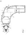
図1は、本発明による鼻水吸引装置1の第1実施形態を示している。
この鼻の分泌物吸引装置1は、鼻側末端部2と、中空本体3とを有している。
この鼻側末端部2は、円錐台(tronconique)形状の中空中央部分4を有し、この中空中央部分は、比較的小さな断面積の端部で、より小さな直径の第2の中空円錐台部分5を有している。この円錐台部分5は、比較的小さな断面積の端部で開口部6を有し、個人の鼻の中へと導入されるために適している。
FIG. 1 shows a first embodiment of a nasal mucus suction device 1 according to the present invention.
This nasal secretion suction device 1 has a nasal end portion 2 and a
The nasal end 2 has a tronconique-shaped hollow
中央の円錐台部分4は、比較的大きな断面積の端部で、円柱状の面を備えた部分により外面が規定されているカラー(couronne)7を有し、このカラーの外面は、ねじ山が設けられている。
The central
このカラー7は、ラテックス又はポリ塩化ビニルから形成されていると好ましい、弾性的に変形可能で不浸透性膜8により防水して(de manie`re e’tanche)封止されている。
この不浸透性膜8を鼻側末端部2に固定することは、形状の相補性により実行される。
The
Fixing the impermeable membrane 8 to the nasal end 2 is performed by shape complementarity.
本発明の他の実施形態によると、不浸透性膜8を鼻側末端部2に固定することは、接着、又は溶接により実行されることができると好都合であり、もしくは、これら2つの部分は、共に成形、又は射出成形されることさえできる。 According to another embodiment of the invention, fixing the impermeable membrane 8 to the nasal end 2 can advantageously be performed by gluing or welding, or these two parts are Can be molded together, or even injection molded.
中空本体3は、真空チャンバ9内に真空を生じさせることを目的とした電気ポンプ10に接続された真空チャンバ9を規定している。
この電気ポンプ10は、この中空本体3内に収容されている複数のバッテリ12により供給された電気モータ11により駆動される。
この電気モータ11は、このモータ11を確実に時間遅延させて動作させる制御手段と関連付けられている。この結果、モータ11は、特定の持続時間の間だけ連続的に動作することができる。このことは、生じる真空を制限するためであり、この結果、モータ11への損傷を防止するためである。
The
The
The electric motor 11 is associated with control means for operating the motor 11 with a certain time delay. As a result, the motor 11 can continuously operate for a specific duration. This is to limit the generated vacuum, and as a result, to prevent damage to the motor 11.
この持続時間を越えると、モータ11は、前記制御手段により停止され、第2の特定の持続時間の後のみに再始動されることができる。 If this duration is exceeded, the motor 11 can be stopped by the control means and restarted only after a second specified duration.
真空チャンバ4は、鼻側末端部2にねじ込むことを目的とした、この鼻側末端部2のカラー7の形状に相補的な形状のねじ付開口部13を内部に有している。
中空本体3の開口部13は、そのねじ付の部分の延長で、鼻側末端部2がこの開口部13にねじ込まれた場合に所定位置でロックする目的の周方向の停止部14により規定されている。
The
The opening 13 of the
鼻側末端部2は、結果として、取外し可能なように中空本体3に取付けられる。
押しボタン15が、その押込み位置で、複数のバッテリ12による電気モータ11への供給を可能とするために、中空本体3に設けられている。
この結果、この押しボタン15を押下した場合、電気ポンプ10は、真空チャンバ9内に真空を発生させ、不浸透性膜8の変形を起こさせる。
この不浸透性膜8が変形すると、真空が鼻側末端部2内に移動し、結果として、鼻の分泌物の吸引が生じる。
The nasal end 2 is consequently attached to the
A
As a result, when the
When this impermeable membrane 8 is deformed, the vacuum moves into the nasal end 2 and, as a result, suction of nasal secretions occurs.
円錐台形状の部分5では、鼻側末端部2は、真空チャンバ9内に真空が発生させられていない場合に、この円錐台形状の部分5の開口部6に、ばね17の作用で当接して維持されるボール16からなる逆止め弁を有している。
In the truncated cone-shaped
図2に示されているように、ばね17の固定領域は、鼻側末端部2の円錐台形状の部分5に頑丈に(en force)取付けられている別個の部品24により形成されている。この別個の部品24は、比較的大きな直径の円筒状の部分25に、4つの同じ長さの一体的な突部19により接続された円筒状で軸方向の部分18により形成されている。
As shown in FIG. 2, the fixing region of the spring 17 is formed by a
図3は、動作中の図1による装置を示している。
真空が真空チャンバ9内に発生された場合、不浸透性膜8は、変形され、真空を鼻側末端部2に移動させる。
ばね17の圧縮が結果として生じ、それにしたがって、ボール16は、もはや鼻側末端部2の円錐台形状の部分5の開口部6を封止せず、鼻の分泌物の吸引が可能となる。
FIG. 3 shows the device according to FIG. 1 in operation.
When a vacuum is generated in the vacuum chamber 9, the impermeable membrane 8 is deformed and moves the vacuum to the nasal end 2.
As a result of the compression of the spring 17, the
真空が不浸透性膜8にかけられるのが止むと、ばね17の作用を受けているボール16は、円錐台形状の部分5の開口部6を再び封止し、この結果、鼻側末端部2の中身を出すこと(vidange)が防止される。
When the vacuum stops being applied to the impermeable membrane 8, the
衛生の理由から、鼻側末端部2が使い捨てあることは好ましい。
したがって、鼻の分泌物吸引装置1を使用後に、使用された鼻側末端部2を中空本体3からねじ取り、それからそれを新しい鼻側末端部2に交換することが可能である。
For hygiene reasons, it is preferred that the nose side end 2 is disposable.
Thus, after using the nasal secretion suction device 1, it is possible to screw the used nasal end 2 from the
このように、前記中空本体と真空源とは、鼻の分泌物によって汚染されず、この装置を各使用後に洗浄し、消毒される必要はない。 Thus, the hollow body and the vacuum source are not contaminated by nasal secretions and the device need not be cleaned and disinfected after each use.
真空チャンバ9は、壁20により規定されており、真空チャンバ9と電気ポンプ10との間の接続を可能にし、不浸透性膜8の変形を制限する余地が有る(susceptible)。
The vacuum chamber 9 is defined by a wall 20 and allows a connection between the vacuum chamber 9 and the
図4は、鼻側末端部2のカラー7を封止する部材の第2実施形態を示している。
本発明のこの実施形態によると、カラー7は、アコーディオンのように折りたたまれたコートされた紙のような不浸透性の素材からなる変形可能な部材21により防水するように封止されている。
この変形可能な部材21の鼻側末端部2への固定は、接着により実行される。
FIG. 4 shows a second embodiment of a member for sealing the
According to this embodiment of the invention, the
The fixing of the deformable member 21 to the nose side end portion 2 is performed by adhesion.
図5は、鼻側末端部2のカラー7を封止する部材の第3実施形態を示している。
本発明のこの実施形態によると、カラー7には、内側にピストン23が収容された円筒状で軸方向の延長部22が備えられており、このピストン23は、真空の作用で、カラー7の領域に位置している位置と、そこから離れた位置との間を移動可能である。
FIG. 5 shows a third embodiment of a member for sealing the
According to this embodiment of the invention, the
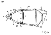
図6は、鼻の分泌物吸引装置1の第4実施形態を示している。
この実施形態では、同一の部材は、同一の参照符号を有している。
第1実施形態に対照的に、鼻側末端部2は、1つの代わりに、2つの部分26、27を有している。
第1の部分26は、第1実施形態と同様に、円錐台形状の中央の中空部分4と、第2の中空の円錐台形状の部分5と、開口部6と、ボール16と、この円錐台形状の部分5に頑丈に取り付けられている部品24とを有している。
FIG. 6 shows a fourth embodiment of the nasal secretion suction device 1.
In this embodiment, the same members have the same reference numerals.
In contrast to the first embodiment, the nasal end 2 has two
As in the first embodiment, the
この実施形態では、特に、円錐台形状の中央の中空部分4は、比較的大きな断面積の端部で、外面に第2の部分27に固定するための手段が設けられた、円筒状で軸方向の管状の延長部28を有している。
In this embodiment, in particular, the frusto-conical central
管状の延長部28の外径は、中央の部分4の比較的大きな断面積の端部で、この中央の部分4の外径未満である。結果として、周方向のエッジ29が形成され、第1の部分26が第2の部分27内にはめ込まれる場合に停止部として作用する。
The outer diameter of the tubular extension 28 is at the end of the relatively large cross-sectional area of the
第2の部分27は、中空であり、ほぼ円錐台形状である。第2の部分27は、中空本体3の開口部13に密閉して取外し可能なように固定するための手段が備えられた第1の開いた端部と、第1の部分26をはめ込むことを目的とした、管状の延長部28の形状に相補的な形状の第2の端部とを有している。
The second portion 27 is hollow and has a substantially truncated cone shape. The second part 27 fits the
ハウジング30が、管状の延長部28の外面に形成され、ハウジング30の形状に対応した形状を備えたつめ(cliquet)31が、部分27の内面に形成されている。このつめ31は、ハウジング30内にはめ込むことを目的とし、これら2つの部材は、分解することができない部分26、27の間の接続を生じさせるためのはめこみ手段を形成している。
A housing 30 is formed on the outer surface of the tubular extension 28, and a cliquet 31 having a shape corresponding to the shape of the housing 30 is formed on the inner surface of the portion 27. This pawl 31 is intended to fit within the housing 30 and these two members form a telescoping means for creating a connection between the
不浸透性膜8は、管状の延長部28の領域にはめ込むことにより固定された2つの部分26、27の間に形成されたハウジング内に保持されることを意図された周方向のフランジ32を有している。
The impermeable membrane 8 has a circumferential flange 32 intended to be held in a housing formed between two
このように、不浸透性膜8は、2つの部分26、27の間にクランプすることにより鼻側末端部2に固定され、2つの部分26、27の間の封止を確実とする。
In this way, the impermeable membrane 8 is secured to the nasal end 2 by clamping between the two
本発明のこの実施形態によると、円錐台形状の部分5では、鼻側末端部2は、ボール16のみからなる逆止め弁を有している。
真空が不浸透性膜8にかけられることが止むと、ボール16は、初期の形状を再び取る傾向を有するこの不浸透性膜8によりかけられる圧力の作用により、円錐台形状の部分5の開口部6を封止する。この結果、鼻側末端部2の中身を出すことを防止する。
According to this embodiment of the invention, in the
When the vacuum stops being applied to the impervious membrane 8, the
鼻の分泌物吸引装置1の使用後、このように、使用された鼻側末端部2を中空本体3から取外し、それから、それを新しい鼻側末端部2と交換することができる。
After use of the nasal secretion aspiration device 1, the used nasal end 2 can thus be removed from the
本発明のこの実施形態によると、鼻の分泌物吸引装置を使用している間、前記膜8は、変形され、第2の部分27の内面に張り付く(se plaquer)。結果として、鼻側末端部2を分解している間、この膜8は、圧縮されず、鼻の分泌物は、鼻側末端部2を出ることができない。この結果、鼻の分泌物が部分的に出ることを防止する。 According to this embodiment of the invention, while using a nasal secretion aspiration device, the membrane 8 is deformed and sticks to the inner surface of the second portion 27. As a result, while disassembling the nasal end 2, this membrane 8 is not compressed and nasal secretions cannot exit the nasal end 2. As a result, partial discharge of nasal secretions is prevented.
図7は、鼻の分泌物吸引装置の第5実施形態を示している。
本発明のこの実施形態によると、不浸透性膜8の周方向フランジ32は、中央部分4の比較的大きい断面積の端部の領域で、第1の部分26の外壁に形成された保持部材33と協働することが意図されている。
FIG. 7 shows a fifth embodiment of the nasal secretion suction device.
According to this embodiment of the invention, the circumferential flange 32 of the impermeable membrane 8 is a retaining member formed on the outer wall of the
2つの部分26、27は、分解されることができないように互いに固定されてはいなく、単にしっかりと取付けられている。
したがって、結果として、鼻の分泌物吸引装置1を使用した後で、使用された鼻側末端部2を中空体3から取外し、それから、不浸透性膜8を部分26から取外し、それを廃棄するために、この第1の部分26を第2の部分27から取外すことができる。
The two
Thus, as a result, after using the nasal secretion suction device 1, the used nasal end 2 is removed from the
本発明のこの実施形態によると、不浸透性膜8のみが使い捨て用であり、鼻側末端部2は、鼻の分泌物吸引装置の各使用後に、洗浄され消毒されなければならない。 According to this embodiment of the invention, only the impermeable membrane 8 is disposable and the nasal end 2 must be cleaned and disinfected after each use of the nasal secretion aspiration device.
本発明が、例としての上述の実施形態に限定されないことは言うまでもなく、本発明は、それにもかかわらず、添付されている請求項により規定される保護の範囲に入る全ての変形例を含んでいる。 It goes without saying that the invention is not limited to the embodiments described above by way of example, and the invention nevertheless includes all variants that fall within the scope of protection defined by the appended claims. Yes.
Claims (16)
真空源(10)に接続されることができ、開口部(13)を有している真空チャンバ(9)を規定している中空本体(3)と、
個人の鼻内に導入されることを目的とし鼻口に適合されている第1の開口端部(5)と、前記中空本体(3)の開口部(13)に防水して取外し可能なように固定するための手段が備えられている第2の開口端部(7、27)とを有する鼻側末端部と
を具備し、
前記鼻側末端部の第2の開口端部(7、27)は、少なくとも一部に、前記中空本体及び前記真空源から流体的に分離された分泌物貯蔵所を規定する不浸透性の部材(8、21、23)により封止され、
前記不浸透性の部材は、前記真空源によって真空チャンバに発生された真空の作用により変形又は移動されることができることを特徴とする鼻の分泌物吸引装置(1)。In the nasal secretion suction device (1),
A hollow body (3) defining a vacuum chamber (9) that can be connected to a vacuum source (10) and has an opening ( 13 );
The first open end (5) adapted to the nostril for introduction into the individual nose and the opening (13) of the hollow body (3) are waterproof and removable. A nasal end having a second open end (7, 27) provided with means for securing to the
The second open end (7, 27) of the nasal end is at least partly impermeable member defining a secretion reservoir fluidly separated from the hollow body and the vacuum source (8, 21, 23) ,
Nasal secretion aspiration device (1), characterized in that the impermeable member can be deformed or moved by the action of a vacuum generated in a vacuum chamber by the vacuum source .
Applications Claiming Priority (2)
| Application Number | Priority Date | Filing Date | Title |
|---|---|---|---|
| FR0411917A FR2877579B1 (en) | 2004-11-09 | 2004-11-09 | DEVICE FOR ASPIRATING NASAL SECRETIONS |
| PCT/FR2005/002770 WO2006051206A1 (en) | 2004-11-09 | 2005-11-07 | Nasal secretion aspiration device |
Publications (2)
| Publication Number | Publication Date |
|---|---|
| JP2008518746A JP2008518746A (en) | 2008-06-05 |
| JP4511599B2 true JP4511599B2 (en) | 2010-07-28 |
Family
ID=34950780
Family Applications (1)
| Application Number | Title | Priority Date | Filing Date |
|---|---|---|---|
| JP2007540675A Expired - Fee Related JP4511599B2 (en) | 2004-11-09 | 2005-11-07 | Nasal secretion suction device |
Country Status (14)
| Country | Link |
|---|---|
| US (1) | US20080208112A1 (en) |
| EP (1) | EP1833527B1 (en) |
| JP (1) | JP4511599B2 (en) |
| KR (1) | KR20070083729A (en) |
| CN (1) | CN101048184A (en) |
| AT (1) | ATE512679T1 (en) |
| AU (1) | AU2005303694A1 (en) |
| BR (1) | BRPI0517678A (en) |
| CA (1) | CA2585746A1 (en) |
| FR (1) | FR2877579B1 (en) |
| IL (1) | IL182801A (en) |
| MX (1) | MX2007005424A (en) |
| NO (1) | NO20072935L (en) |
| WO (1) | WO2006051206A1 (en) |
Families Citing this family (19)
| Publication number | Priority date | Publication date | Assignee | Title |
|---|---|---|---|---|
| US8435207B2 (en) | 2006-11-06 | 2013-05-07 | Aardvark Medical, Inc. | Irrigation and aspiration devices and methods |
| US8827945B2 (en) | 2006-11-06 | 2014-09-09 | Aardvark Medical, Inc. | Irrigation and aspiration devices and methods |
| EP2083877A2 (en) | 2006-11-06 | 2009-08-05 | Aardvark Medical, LLC | Irrigation and aspiration device and method |
| FR2909288B1 (en) * | 2006-12-01 | 2009-02-06 | Jose Bensoussan | NASAL TIP FOR NASAL SECRETION SUCTION DEVICE AND NASAL SECRET ASPIRATION DEVICE COMPRISING THE NASAL TIP |
| US8048023B2 (en) | 2007-03-06 | 2011-11-01 | Rhinosystems Inc. | Systems and methods for nasal irrigation |
| ES1067564Y (en) * | 2007-11-08 | 2008-09-01 | De La Cruz Jose Cobo | VACUUM CLEANER OF THE NASAL SECRETIONS OF THE INFANT WITH A NON-INDUCTIVE DEVICE OF POLLUTION AND TRANSMISSION OF PATHOGEN GERMANS. |
| US8070744B1 (en) * | 2008-02-01 | 2011-12-06 | Clements Clara C | Nasal aspiration device |
| JP5999787B2 (en) | 2011-07-18 | 2016-09-28 | ライノシステムズ インク.Rhinosystems,Inc. | Nasal irrigation device and system having prefabricated imitation cartridge elements |
| KR101225546B1 (en) * | 2012-03-20 | 2013-01-23 | 정성관 | Snivel inhaler installed vacuum tank |
| EP3789022A1 (en) | 2012-12-27 | 2021-03-10 | Massachusetts Eye & Ear Infirmary | Treatment of rhinosinusitis with p-glycoprotein inhibitors |
| WO2017123933A1 (en) | 2016-01-15 | 2017-07-20 | Massachusetts Eye And Ear Infirmary | Secreted p-glycoprotein is a non-invasive biomarker of chronic rhinosinusitis |
| FR3050938B1 (en) * | 2016-05-09 | 2021-12-10 | Michel Brun | BABY FLY BY SUCTION WITH SANITIZER FILTER |
| US20180296740A1 (en) * | 2017-04-14 | 2018-10-18 | Yulia MARKMAN | Nasal irrigator |
| USD883470S1 (en) * | 2019-10-23 | 2020-05-05 | Junjie Wei | Nasal aspirator |
| US11439487B2 (en) * | 2020-07-03 | 2022-09-13 | Edison Sangwoo Han | Systems and methods for an evacuator adapter |
| US11904084B2 (en) * | 2020-12-12 | 2024-02-20 | Medhat N. Elmasry | Ultraportable and adjustable nose, ear, and wound aspirator and irrigator device and related methods |
| TWI796165B (en) * | 2022-03-15 | 2023-03-11 | 北群醫學科技股份有限公司 | nasal suction device |
| USD1013151S1 (en) * | 2022-05-17 | 2024-01-30 | Hetaida Technology Co., Ltd. | Electric nasal aspirator |
| CN115671412A (en) * | 2022-07-27 | 2023-02-03 | 丽水市华荟科技有限公司 | Nasal aspirator |
Family Cites Families (15)
| Publication number | Priority date | Publication date | Assignee | Title |
|---|---|---|---|---|
| US1882040A (en) * | 1930-03-08 | 1932-10-11 | William A Roehm | Suction-massage apparatus |
| US3032037A (en) * | 1958-06-20 | 1962-05-01 | Jennie L Havirco | Means for the extraction and storage of blood |
| US3906940A (en) * | 1974-08-26 | 1975-09-23 | Sohji Kawada | Facial treatment device |
| JPH026052U (en) * | 1988-06-24 | 1990-01-16 | ||
| US5098418A (en) * | 1989-08-24 | 1992-03-24 | Maitz Carlos A | Aspirator device for body fluids |
| US6203321B1 (en) * | 1996-06-03 | 2001-03-20 | Kevin Helmer | Backflow prevention system in suctioning apparatus |
| US5782837A (en) * | 1997-04-23 | 1998-07-21 | York; Richard | Esophagus clearing device |
| US5941847A (en) * | 1998-02-06 | 1999-08-24 | Medela Holding Ag | Breast shield with vacuum isolation element |
| CA2288455A1 (en) * | 1999-05-12 | 2000-11-12 | G-Intek Co., Ltd. | A portable snivel inhaler |
| US6059803A (en) * | 1999-06-01 | 2000-05-09 | Spilman; Daniel A. | Ear vacuum |
| KR100360605B1 (en) * | 2000-08-17 | 2002-11-18 | 주식회사 지인텍 | Medical instruments |
| US6595949B1 (en) * | 2000-09-05 | 2003-07-22 | Jeffrey Bryan Shapiro | Automatic mucus removal device |
| DE20107051U1 (en) * | 2001-04-24 | 2001-07-19 | Soaring Benefit Ltd | Cleanable, polyfunctional nasal mucus suction device |
| US6517511B2 (en) * | 2001-06-22 | 2003-02-11 | Tzu-Chiang Yao | Cleansable multi-purpose nasal discharge aspirator |
| EP1485146B1 (en) * | 2002-02-25 | 2013-08-07 | Sequana Medical AG | Vesicular shunt for the drainage of excess fluid |
-
2004
- 2004-11-09 FR FR0411917A patent/FR2877579B1/en not_active Expired - Fee Related
-
2005
- 2005-11-07 CN CNA2005800367861A patent/CN101048184A/en active Pending
- 2005-11-07 CA CA002585746A patent/CA2585746A1/en not_active Abandoned
- 2005-11-07 MX MX2007005424A patent/MX2007005424A/en active IP Right Grant
- 2005-11-07 US US11/718,926 patent/US20080208112A1/en not_active Abandoned
- 2005-11-07 WO PCT/FR2005/002770 patent/WO2006051206A1/en active Application Filing
- 2005-11-07 AU AU2005303694A patent/AU2005303694A1/en not_active Abandoned
- 2005-11-07 AT AT05815187T patent/ATE512679T1/en not_active IP Right Cessation
- 2005-11-07 JP JP2007540675A patent/JP4511599B2/en not_active Expired - Fee Related
- 2005-11-07 KR KR1020077008919A patent/KR20070083729A/en not_active Application Discontinuation
- 2005-11-07 EP EP05815187A patent/EP1833527B1/en not_active Not-in-force
- 2005-11-07 BR BRPI0517678-6A patent/BRPI0517678A/en not_active IP Right Cessation
-
2007
- 2007-04-26 IL IL182801A patent/IL182801A/en not_active IP Right Cessation
- 2007-06-08 NO NO20072935A patent/NO20072935L/en not_active Application Discontinuation
Also Published As
| Publication number | Publication date |
|---|---|
| MX2007005424A (en) | 2007-05-16 |
| JP2008518746A (en) | 2008-06-05 |
| KR20070083729A (en) | 2007-08-24 |
| EP1833527A1 (en) | 2007-09-19 |
| BRPI0517678A (en) | 2008-10-14 |
| NO20072935L (en) | 2007-08-08 |
| IL182801A (en) | 2010-11-30 |
| FR2877579B1 (en) | 2007-01-19 |
| IL182801A0 (en) | 2007-08-19 |
| CA2585746A1 (en) | 2006-05-18 |
| US20080208112A1 (en) | 2008-08-28 |
| WO2006051206A1 (en) | 2006-05-18 |
| EP1833527B1 (en) | 2011-06-15 |
| CN101048184A (en) | 2007-10-03 |
| FR2877579A1 (en) | 2006-05-12 |
| ATE512679T1 (en) | 2011-07-15 |
| AU2005303694A1 (en) | 2006-05-18 |
Similar Documents
| Publication | Publication Date | Title |
|---|---|---|
| JP4511599B2 (en) | Nasal secretion suction device | |
| EP0271620B1 (en) | Manually operable aspirator | |
| US7779842B1 (en) | Suction system with high efficiency suction control valve | |
| US6923184B1 (en) | Suction system with high efficiency suction control valve | |
| EP2424585B1 (en) | Nasal aspirator | |
| US8752579B2 (en) | Check valve for fluid injector | |
| US10888673B2 (en) | Counterbalanced nasal bulb aspirator | |
| KR20180033169A (en) | Method for controlling periodontal cleaning device and periodontal cleaning device | |
| CN110841118B (en) | Child nursing sputum suction device for completing sputum suction process of oral cavity and nasal cavity at one time | |
| US5855478A (en) | Method for preventing back flow in a dental saliva ejector | |
| EP1474186B1 (en) | Infant nasal aspirator | |
| JP3120415B2 (en) | Irrigation suction catheter | |
| KR101368976B1 (en) | Nasal mucus aspirator | |
| WO2019104081A1 (en) | Hygienic nasal aspirator | |
| CN104258480A (en) | Nasal aspirator | |
| KR200481166Y1 (en) | Snivel suction instrument | |
| CN210612590U (en) | Sputum suction tube and sputum aspirator with same | |
| CN217366666U (en) | Nasal mucus sucking device | |
| CN111035817A (en) | Oral nursing sputum suction tube | |
| KR200234171Y1 (en) | Runny nose | |
| CN207837935U (en) | Closed atomization suction sputum integral tube | |
| JP2015002784A (en) | Suction tool for sucking foreign body in mouth | |
| CA1270414A (en) | Manually operable aspirator | |
| JP3008701U (en) | Simple suction device | |
| JP3101748U (en) | Cleaning liquid feeder |
Legal Events
| Date | Code | Title | Description |
|---|---|---|---|
| A621 | Written request for application examination |
Free format text: JAPANESE INTERMEDIATE CODE: A621 Effective date: 20080905 |
|
| A977 | Report on retrieval |
Free format text: JAPANESE INTERMEDIATE CODE: A971007 Effective date: 20091116 |
|
| A131 | Notification of reasons for refusal |
Free format text: JAPANESE INTERMEDIATE CODE: A131 Effective date: 20091208 |
|
| A521 | Request for written amendment filed |
Free format text: JAPANESE INTERMEDIATE CODE: A523 Effective date: 20100308 |
|
| TRDD | Decision of grant or rejection written | ||
| A01 | Written decision to grant a patent or to grant a registration (utility model) |
Free format text: JAPANESE INTERMEDIATE CODE: A01 Effective date: 20100406 |
|
| A01 | Written decision to grant a patent or to grant a registration (utility model) |
Free format text: JAPANESE INTERMEDIATE CODE: A01 |
|
| A61 | First payment of annual fees (during grant procedure) |
Free format text: JAPANESE INTERMEDIATE CODE: A61 Effective date: 20100506 |
|
| FPAY | Renewal fee payment (event date is renewal date of database) |
Free format text: PAYMENT UNTIL: 20130514 Year of fee payment: 3 |
|
| R150 | Certificate of patent or registration of utility model |
Free format text: JAPANESE INTERMEDIATE CODE: R150 |
|
| LAPS | Cancellation because of no payment of annual fees |