JP4511094B2 - Method and apparatus for crossing line spectral information quantization method in speech coder - Google Patents
Method and apparatus for crossing line spectral information quantization method in speech coder Download PDFInfo
- Publication number
- JP4511094B2 JP4511094B2 JP2001511670A JP2001511670A JP4511094B2 JP 4511094 B2 JP4511094 B2 JP 4511094B2 JP 2001511670 A JP2001511670 A JP 2001511670A JP 2001511670 A JP2001511670 A JP 2001511670A JP 4511094 B2 JP4511094 B2 JP 4511094B2
- Authority
- JP
- Japan
- Prior art keywords
- vector
- moving average
- frame
- quantization
- speech
- Prior art date
- Legal status (The legal status is an assumption and is not a legal conclusion. Google has not performed a legal analysis and makes no representation as to the accuracy of the status listed.)
- Expired - Lifetime
Links
Images


Classifications
-
- G—PHYSICS
- G10—MUSICAL INSTRUMENTS; ACOUSTICS
- G10L—SPEECH ANALYSIS OR SYNTHESIS; SPEECH RECOGNITION; SPEECH OR VOICE PROCESSING; SPEECH OR AUDIO CODING OR DECODING
- G10L19/00—Speech or audio signals analysis-synthesis techniques for redundancy reduction, e.g. in vocoders; Coding or decoding of speech or audio signals, using source filter models or psychoacoustic analysis
- G10L19/04—Speech or audio signals analysis-synthesis techniques for redundancy reduction, e.g. in vocoders; Coding or decoding of speech or audio signals, using source filter models or psychoacoustic analysis using predictive techniques
- G10L19/06—Determination or coding of the spectral characteristics, e.g. of the short-term prediction coefficients
- G10L19/07—Line spectrum pair [LSP] vocoders
-
- G—PHYSICS
- G10—MUSICAL INSTRUMENTS; ACOUSTICS
- G10L—SPEECH ANALYSIS OR SYNTHESIS; SPEECH RECOGNITION; SPEECH OR VOICE PROCESSING; SPEECH OR AUDIO CODING OR DECODING
- G10L19/00—Speech or audio signals analysis-synthesis techniques for redundancy reduction, e.g. in vocoders; Coding or decoding of speech or audio signals, using source filter models or psychoacoustic analysis
- G10L19/02—Speech or audio signals analysis-synthesis techniques for redundancy reduction, e.g. in vocoders; Coding or decoding of speech or audio signals, using source filter models or psychoacoustic analysis using spectral analysis, e.g. transform vocoders or subband vocoders
- G10L19/032—Quantisation or dequantisation of spectral components
- G10L19/038—Vector quantisation, e.g. TwinVQ audio
-
- G—PHYSICS
- G10—MUSICAL INSTRUMENTS; ACOUSTICS
- G10L—SPEECH ANALYSIS OR SYNTHESIS; SPEECH RECOGNITION; SPEECH OR VOICE PROCESSING; SPEECH OR AUDIO CODING OR DECODING
- G10L19/00—Speech or audio signals analysis-synthesis techniques for redundancy reduction, e.g. in vocoders; Coding or decoding of speech or audio signals, using source filter models or psychoacoustic analysis
- G10L19/04—Speech or audio signals analysis-synthesis techniques for redundancy reduction, e.g. in vocoders; Coding or decoding of speech or audio signals, using source filter models or psychoacoustic analysis using predictive techniques
- G10L19/16—Vocoder architecture
- G10L19/18—Vocoders using multiple modes
- G10L19/22—Mode decision, i.e. based on audio signal content versus external parameters
-
- G—PHYSICS
- G10—MUSICAL INSTRUMENTS; ACOUSTICS
- G10L—SPEECH ANALYSIS OR SYNTHESIS; SPEECH RECOGNITION; SPEECH OR VOICE PROCESSING; SPEECH OR AUDIO CODING OR DECODING
- G10L19/00—Speech or audio signals analysis-synthesis techniques for redundancy reduction, e.g. in vocoders; Coding or decoding of speech or audio signals, using source filter models or psychoacoustic analysis
- G10L2019/0001—Codebooks
- G10L2019/0004—Design or structure of the codebook
- G10L2019/0005—Multi-stage vector quantisation
-
- G—PHYSICS
- G10—MUSICAL INSTRUMENTS; ACOUSTICS
- G10L—SPEECH ANALYSIS OR SYNTHESIS; SPEECH RECOGNITION; SPEECH OR VOICE PROCESSING; SPEECH OR AUDIO CODING OR DECODING
- G10L25/00—Speech or voice analysis techniques not restricted to a single one of groups G10L15/00 - G10L21/00
- G10L25/03—Speech or voice analysis techniques not restricted to a single one of groups G10L15/00 - G10L21/00 characterised by the type of extracted parameters
- G10L25/12—Speech or voice analysis techniques not restricted to a single one of groups G10L15/00 - G10L21/00 characterised by the type of extracted parameters the extracted parameters being prediction coefficients
Abstract
Description
【0001】
【発明の属する技術分野】
本発明は一般的に音声処理、そしてより明確には音声コーダにおいて、線スペクトル情報を量子化するための方法および装置に関する。
【0002】
【従来の技術】
ディジタル技術による音声の伝送は、とくに長距離およびディジタル無線電話応用において広く使用されている。このことは、ひき続いて再構成された音声の認識された品質を維持しながら、チャネルに送ることのできる情報の最小量を決定することに関する、関心をひき起こしてきている。もしも音声が単にサンプリングおよびディジタイジングによって伝送されるならば、現在のアナログ電話の音声品質に到達するためには、64キロビット/秒(kbps)のオーダーのデータレートが必要である。しかしながら、適切な符号化、伝送、そして受信機における再組立に続く音声解析の使用によって、データレートの大きな減少が達成可能である。
【0003】
音声を圧縮するためのデバイスは、通信の多くの分野において使用されている。典型的な分野は無線通信である。無線通信の分野は、たとえばコードレス電話、ページング、無線ローカルループ、セルラおよびPCS電話システムのような無線電話、移動インターネットプロトコル電話、そして衛星通信システムなど多くの応用を含んでいる。とくに重要な応用は移動加入者に対する無線電話である。
【0004】
たとえば、周波数分割マルチプルアクセス(FDMA)、時間分割マルチプルアクセス(TDMA)、そしてコード分割マルチプルアクセス(CDMA)を含む無線通信システムに対する、種々の空間に対するインターフェースが開発されてきている。それに関連して、たとえばアドバンスドモービルホンサービス(AMPS)、グローバルシステムフォーモービルコミュニケーションズ(GSM)、そして暫定標準95(IS‐95)を含む種々の国内および国際規格が制定されてきている。典型的な無線電話通信システムは、コード分割マルチプルアクセス(CDMA)システムである。IS‐95規格およびその派生規格、IS‐95A、ANSI J‐STD‐008、IS‐95B、提案されている第3世代の規格IS‐95CおよびIS‐2000等(ここではまとめてIS‐95として参照する)は、通信機械工業会(TIA)および他の有名な規格団体によって、セルラあるいはPCS電話通信システムに対する、CDMAの空間に対するインターフェースの使用を明確に述べるために発布されている。IS‐95規格の使用に従って、実質的に形成された典型的な無線通信システムは、米国特許5,103,459および4,901,307に記述されており、これらの特許は、本発明の譲渡人に譲渡され、参照によって完全に本発明に組み入れられている。
【0005】
人間の音声発生の模型に関するパラメータを抽出することによって、音声を圧縮する手法を用いたデバイスは、音声コーダと呼ばれる。音声コーダは、到来音声信号を時間のブロック、あるいは解析フレームに分割する。音声コーダは、典型的には符号器および復号器を含む。符号器は正確な、適切なパラメータを抽出するために到来音声フレームを分析し、そしてそこで、パラメータをバイナリ表現に、すなわち、ビットの組み合わせすなわちバイナリデータパケットに量子化する。データパケットは、通信チャネルを通して受信機そして復号器に送信される。復号器はデータパケットを処理し、それらをパラメータが発生するように非 量子化(unquantize)し、そして、その非量子化されたパラメータを用いて音声フレームに再組立する。
【0006】
音声コーダの機能は、ディジタイズされた音声信号を、音声に固有の自然な冗長度のすべてを除くことによって、低いビットレートの信号に圧縮することである。ディジタル圧縮は入力音声フレームを、パラメータの組み合わせで表現することによって、またパラメータをビットの組み合わせで表現するために量子化を用いることによって達成される。もしも入力音声フレームがビット数Niを有し、オンセイコーダによって作られたデータパケットがビット数Noを有するならば、音声コーダによって達成された圧縮係数は、Cr=Ni/Noである。課題は、目標圧縮係数を達成する一方で、復号化された音声の高い音声品質を保つことである。音声コーダの特性は、(1)いかに適切に、音声モデル、あるいは上に述べた解析と組立過程の組み合わせを実行するか、そして、(2)フレームあたりNoビットの目標ビットレートにおいて、いかに適切に、パラメータ量子化過程が実行されるか、にかかっている。このように、音声モデルの目標は、各フレームに対して小さなパラメータ組み合わせで、音声信号の本質、あるいは目標とする音声品質をとらえることである。
【0007】
多分音声コーダの設計において最も重要なものは、音声信号を記述するための適切なパラメータの組み合わせ(ベクトルを含む)に対する研究である。パラメータの適切な組み合わせは、知覚的に正確な音声信号の再構成に対して、低いシステム帯域幅を要求する。ピッチ、信号パワー、スペクトル包絡(すなわちフォルマント)、振幅そして位相スペクトルは、音声符号化パラメータの例である。
【0008】
音声コーダは、一度に音声の小さいセグメント(典型的に5ミリ秒(ms)サブフレーム)を符号化する高時間分解能処理を用いることによって、時間領域音声波形を捕捉することを試みている、時間領域コーダとして実施されるかもしれない。各サブフレームに対して、コードブックスペースからの高精度標本が、この業界ではよく知られている種々の探索アルゴリズムによって見いだされる。あるいは音声コーダは、パラメータ(解析)の組み合わせからなる入力音声フレームの短期間の音声スペクトルを捕捉することを試み、そしてスペクトルパラメータから音声波形を再生するのに対応する組立過程を用いている、周波数領域コーダとして実施されるかもしれない。パラメータ量子化器は、A.Gersho & R.M.Gray、「ベクトル量子化および信号圧縮」(1992)に記述されている、よく知られた量子化手法に従って、符号ベクトルの蓄えられた表現でそれらを表現することによってパラメータを保存する。
【0009】
よく知られた時間領域音声コーダは、L.B.Rabiner & R.W.Schfar、「音声信号のディジタル処理」396‐453(1978)に記述されたコードエキサイテッドリニアプレディクティブ(CELP)コーダである。そしてそれは参照によって本発明に完全に組み込まれている。CELPコーダにおいて、音声信号内の短期間相関すなわち冗長性は、短期間フォルマントフィルタの係数を探す、線形予測解析によって除去される。短期間予測フィルタの到来音声フレームへの適用は線形予測残留信号を発生し、そしてそれは、さらに長期間予測フィルタパラメータおよびこれに続く確率コードブックによってさらにモデル化され量子化される。このように、CELP符号化は、時間領域音声波形を符号化するタスクを、線形予測短期間フィルタ係数を符号化するタスクと、線形予測残留を符号化するタスクとに分割する。時間領域符号化は固定されたレート(すなわち各フレームに対して同じビット数Noを用いて)で、あるいは種々のレート(この場合はフレーム内容の異なった形式に対して異なったビットレートが用いられる)で、実行することができる。可変レート符号器は、コーデックパラメータを、目標品質を得るのに適切なレベルに、符号化するのに必要な、ビット量のみを用いることを試みている。典型的な可変レートCELPコーダは、本発明の譲渡人に譲渡され、そして参照によって本発明に完全に組み入れられている、米国特許5,414,796に記述されている。
【0010】
CELPコーダのような時間領域コーダは、典型的に時間領域音声波形の精度を保つために、高いフレームあたりのビット数Noに頼っている。このようなコーダは典型的に、比較的高い(たとえば8kbpsあるいはそれ以上)フレームあたりのビット数Noによって与えられる非常に優れた音声品質を備えている。しかしながら、低いビットレート(4kbpsあるいはそれ以下)においては、時間領域コーダは利用できるビット数が制限されることによって高い品質と強い機能とを保つことができない。低いビットレートにおいて、制限されたコードブックスペースは、従来の時間領域コーダにおける、より高いレートの商業用途にうまく展開している波形整合能力を切り落とす。このため、絶えざる改善にもかかわらず、低いビットレートで動作している多くのCELP符号化システムは、典型的に雑音と特性づけられる、知覚的に大きな歪みを受ける。
【0011】
現在、中位から低いビットレート(すなわち2.4から4kbps、あるいはそれ以下)で動作する高品質の音声コーダを開発するという研究的関心と、強い商業的ニーズの波が存在する。応用分野は、無線電話、衛星通信、インターネット電話、種々のマルチメディア、そして音声ストリーミング応用、音声メール、そして他の音声蓄積システムを含む。推進力は、高容量に対するニーズおよびパケット損失状況下における強力な機能に対する要求である。種々の最近の音声符号化標準化努力は、低レート音声符号化アルゴリズム研究と開発を推進する他の直接な推進力である。低レート音声コーダは、許容できる使用帯域幅あたりのさらなるチャネル、すなわちユーザを作り出し、そして適切なチャネル符号化に関しての、付加的な積み重ねと結びついた低レート音声コーダは、符号器規格の総体的ビット予算に適合することができ、そしてチャネル誤り条件のもとで強い機能を確保する。
【0012】
低いビットレートにおいて音声を効率的に符号化する有効な手法はマルチモード符号化である。典型的なマルチモード符号化手法は、「可変レート音声符号化」と題する、1998年12月21日に提出され、本発明の譲渡人に譲渡され、そして参照によって本発明に完全に組み込まれている、米国アプリケーションシリアル番号09/217,341の中に記述されている。従来のマルチモード符号器は、入力音声フレームの異なった形式に対して、異なったモード、あるいは符号化‐復号化アルゴリズムを適用する。各モードあるいは符号化‐復号化過程は、たとえば、有声音声、無声音声、遷移音声(たとえば有声および無声の中間)、そして背景雑音(非音声)など音声セグメントに関する確実な形式を最適に表現するために、もっとも効率的な方法でカスタマイズされる。外部の、開ループモード決定メカニズムは、入力音声フレームを吟味し、フレームに対してどのモードを適用するかに関する決定を下す。開ループモード決定は、典型的に入力フレームからいくつかのパラメータを抽出し、確実な、一時的な、そしてスペクトルの特性に関してパラメータを評価し、そして評価の上にモード決定の基礎を置くことによって行われる。
【0013】
多くの従来の音声コーダにおいては、線スペクトル対あるいは線スペクトル余弦などの線スペクトル情報は、有声音声の定常的な性質を利用することなく、符号化レートを十分に減少させることなしに、有声音声フレームの符号化によって送信される。そこで、価値のある帯域幅が浪費される。他の従来の音声コーダ、マルチモード音声コーダ、あるいは低ビットレート音声コーダにおいては、有声音声の定常性は、各フレームに対して利用される。したがって非定常状態フレームは劣化し、音声品質は損なわれる。各フレームの音声含有量の性質に反応する適応符号化方法を与えることは有利であろう。その上音声信号は一般的に非定常的、すなわち非静的であるので、音声符号化に用いられる線スペクトル情報パラメータの量子化の効率は、音声の各フレームの線スペクトル情報パラメータが、移動平均予測に基づいたベクトル量子化を使用するか、あるいは他の標準ベクトル量子化方法を使用するかの何れかによって、選択的に符号化する方式を使用することにより、改善することができるかもしれない。このような方式は、上記二つのベクトル量子化方法の何れかの利益を有利に利用するであろう。したがって、この二つの量子化方法を、一つの方法から他への遷移境界においては適切に混合することによって交錯する音声コーダを与えることが望ましい。このように、周期的フレームおよび非周期的フレーム間の変化に適応するために、マルチプルベクトル量子化方法を用いる音声コーダに対するニーズが存在する。
【0014】
【課題を解決するための手段】
本発明は、周期的フレームおよび非周期的フレーム間の変化に適応するために、マルチプルベクトル量子化方法を使用する音声コーダに向けられている。よって発明の一つの観点においては、音声コーダは、フレームを解析し、それに基づき線スペクトル情報符号ベクトルを発生するように形成された線形予測フィルタと、そして、線形予測フィルタと結合し、非移動平均予測に基づいたベクトル量子化方法による第一のベクトル量子化手法を用いて、線スペクトル情報ベクトルをベクトル量子化するように形成された量子化器(quantizer)とを有利に含んでおり、そしてそこで、量子化器は、第一の手法のための等価移動平均符号ベクトルを計算し、音声コーダによって前に処理された、予め設定されたフレーム数に対する符号ベクトルの移動平均コードブックのメモリをこの等価移動平均コードブックで更新し、更新された移動平均コードブックのメモリに基づいて第二の手法のための目標量子化ベクトルを計算し、量子化された目標符号ベクトルを発生するために、移動平均予測に基づいた方法を用いている第二のベクトル量子化手法で目標量子化ベクトルをベクトル量子化し、移動平均コードブックのメモリを量子化された目標符号ベクトルで更新し、そして量子化された目標符号ベクトルから量子化された線スペクトル情報を計算するようにさらに配置されている。
【0015】
発明の他の観点においては、非移動平均予測に基づいたベクトル量子化方法を用いている第一の技術と、移動平均予測に基づいたベクトル量子化手法を用いている第二の技術と、この第一と第二の量子化ベクトル量子化技術を用いている、フレームの線スペクトル情報ベクトルをベクトル量子化する方法は、線スペクトル情報ベクトルを第一のベクトル量子化手法でベクトル量子化し、第一の手法のための等価移動平均符号ベクトルを計算し、音声コーダによって前に処理された予め設定されたフレーム数に対する符号ベクトルの移動平均コードブックのメモリを、移動平均符号ベクトルで更新し、更新された移動平均コードブックのメモリに基づいて第二の手法のための目標量子化ベクトルを計算し、目標量子化ベクトルを量子化された目標符号ベクトルを発生するために第二のベクトル量子化手法でベクトル量子化し、量子化された目標符号ベクトルで移動平均コードブックベクトルのメモリを更新し、そして量子化された目標符号ベクトルから、量子化された線スペクトル情報ベクトルを導出するステップを有利に含む。
【0016】
発明の他の観点においては、音声コーダは、非移動平均予測に基づいたベクトル量子化方法を用いる第一のベクトル量子化手法でフレームの線スペクトル情報ベクトルをベクトル量子化するための手段、第一の手法のための等価移動平均符号ベクトルを計算するための手段、音声コーダによって前に処理された予め設定されたフレーム数に対する符号ベクトルの移動平均コードブックのメモリを等価移動平均符号ベクトルで更新するための手段、更新された移動平均コードブックメモリに基づき第二の手法のための目標量子化ベクトルを計算するための手段、量子化された目標符号ベクトルを発生するために、目標量子化ベクトルを第二の目標量子化手法を用いてベクトル量子化するための手段、移動平均コードブックのメモリを量子化された目標符号ベクトルで更新するための手段、そして量子化された目標符号ベクトルから量子化された線スペクトル情報ベクトルを導出するための手段を有利に含む。
【0017】
【発明の実施の形態】
以下に述べる典型的な実施例は、CDMAの空間に対するインターフェースを用いて形成された無線電話通信システムに属する。それにも拘らず、当業者によって、この発明の特徴を具体化しているサブサンプリング法および装置は、当業者に知られている広範囲の技術を用いている、種々の通信システムの何れにも属するかも知れないことを、了解されるべきであろう。
【0018】
図1に説明したように、CDMA無線電話システムは、一般的に、複数の移動加入者ユニット10、複数の基地局12、基地局制御器(BSCs)14、そして移動スイッチングセンター(MSC)16を含む。移動スイッチングセンター16は、従来の公衆交換電話回路網(PSTN)18とインターフェースを形成する。移動スイッチングセンター16はまた、基地局制御器14ともインターフェースを形成する。基地局制御器14は迂回中継線を経て基地局12と結合されている。迂回中継線は、たとえばE1/T1、ATM、IP、PPP,フレームリレー、HDSL、ADSL、あるいはxDSLを含む、いくつかの既知のインターフェースの何れをも支持するよう形成されているかもしれない。システム内には、二つより多くの基地局制御器14があるかもしれないことは了解される。各基地局12は、有利に、少なくとも一つのセクタ(図示せず)を含み、各セクタは、全方向性アンテナあるいは、基地局12から特定方向に放射状に離れた点にあるアンテナを含む。代わりに、各セクタは、ダイバーシティ受信のための二つのアンテナを含むかもしれない。各基地局12は、好都合に、複数の周波数割り当てを支持するように設計されているかも知れない。セクタの交点(intersection)および周波数の割り当ては、CDMAチャネルとして参照されるかもしれない。基地局12はまた、基地局トランシーバサブシステム(BTSs)12として知られるかもしれない。代わりに、“基地局”は産業界において、基地局制御器(BSC)14および一つあるいはそれ以上の基地局トランシーバサブシステムをまとめて参照するために使用されるかもしれない。基地局トランシーバサブシステム12はまた、“セルサイト”12と表示されるかもしれない。代わりに、与えられた基地局トランシーバサブシステム(BTS)12の個々のセクタは、セルサイトとして参照されるかもしれない。移動加入者ユニット10は、典型的にセルラ、あるいはPCS電話10である。システムは、有利に、IS‐95標準に従った使用のために形成される。
【0019】
セルラ電話システムの典型的動作の期間中、基地局12は、一連の移動ユニット10から、一連の逆方向リンク信号を受信する。移動ユニット10は、電話呼あるいは他の通信を処理する。与えられた基地局12によって受信された、各逆方向リンク信号は、その基地局12の中で処理される。その結果のデータは、基地局制御器14に転送される。基地局制御器14は、基地局12間のソフトハンドオフの調和的総合化を含む、コールリソースアロケーション(call resourece allocation)および、移動性マネージメントファンクショナリティ(mobility management functionality)を与える。基地局制御器14はまた、受信データを移動スイッチングセンター16に送る。そして移動スイッチングセンター16は、公衆交換電話回路網18とのインターフェースに対して付加的な経路支持サービスを与える。同様に、公衆交換電話回路網18は移動スイッチングセンター16とインターフェース接続し、そして移動スイッチングセンター16は、基地局制御器14とインターフェース接続する。基地局制御器14は、順番に基地局12を、一連の順方向リンク信号を一連の移動ユニット10に送信するよう制御する。
【0020】
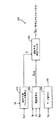
図2において、第1の符号器100は、ディジタル化された音声サンプルs(n)を受信し、第1の復号器104に対して、伝送媒体102あるいは通信チャネル102上に送信するためにサンプルs(n)を符号化する。復号器104は、符号化された音声サンプルを復号し、出力音声信号ssynth(n)を組立てる。反対方向への送信のためには、第2の符号器106が、ディジタル化された音声サンプルs(n)を符号化し、通信チャネル108上に送信される。第2の復号器110は、符号化された音声サンプルを受信し、組立てられた出力音声信号ssynth(n)を発生しながら復号する。
【0021】
音声サンプルs(n)は、たとえばパルス符号変調(PCM)、コンパンデッドμ‐law、あるいはA‐lawを含む、当業界では知られた種々の方法のどれかに従って、ディジタル化され量子化されている音声信号を示す。当業界においては知られているように、音声サンプルs(n)は、入力データのフレームに構造化され、そこで各フレームはディジタル化された音声サンプルs(n)の、予め設定された数を含んでいる。典型的実施例においては、8kHzのサンプリングレートが、160のサンプルを含んでいる各20ミリ秒のフレームとともに使用される。以下に述べる実施例においては、データ送信のレートは、フレームツーフレーム基準で、13.2kbps(フルレート)から6.2kbps(ハーフレート)に、2.6kbps(4分の1レート)に、1kbps(8分の1レート)に、有利に変えられるかもしれない。データ送信レートが変化することは、より低いビットレートは、比較的少ない音声情報を含んでいるフレームに対して選択的に使用されるかもしれないために、好都合である。当業者により了解されるように、他のサンプリングレート、フレームサイズ、そしてデータ送信レートが使用されるかもしれない。
【0022】
第1の符号器100および第2の復号器110は、ともに第1の音声コーダ、すなわち音声コーデックを含む。音声コーダは、たとえば、図1を参照して前に述べた、加入者ユニット、基地局トランシーバサブシステム、あるいは基地局制御器を含む音声信号を送信するためのいずれの通信デバイスにおいても使用可能であろう。同様にして、第2の符号器106、および第1の復号器104はともに第2の音声コーダを含んでいる。当業者によって、音声コーダは、ディジタル信号処理装置(DSP)、特定用途向け集積回路(ASIC)、ディスクリートゲートロジック、ファームウエア、あるいは、いずれの従来のプログラマブルソフトウエアモジュールおよびマイクロ処理装置を用いて、実行されるかもしれないことは理解される。ソフトウエアモジュールは、ランダムアクセスメモリ、フラッシュメモリ、抵抗器、あるいは、当業界で知られている、いずれの他の書き込み可能な蓄積媒体の形態内に属することができるであろう。代わりに、いずれの従来の処理装置、制御器あるいはステートマシンがマイクロ処理装置に代わって置き換えられるであろう。音声符号化用にとくに設計された典型的な特定用途向け集積回路は、本発明の譲渡人に譲渡され、参照によって本発明に完全に組み込まれている、米国特許5,727,123、および、「ボコーダ用途向け集積回路」と題する、1994年2月16日に提出され、本発明の譲渡人に譲渡され、参照によって本発明に完全に組み込まれている、米国アプリケーションシリアル番号08/197,417の中に記述されている。
【0023】
図3において、音声符号器に用いられるかもしれない符号器200は、モード決定モジュール202、ピッチ評価モジュール204、線形予測解析モジュール206、線形予測解析フィルタ208、線形予測量子化モジュール210、そして残留量子化モジュール212を含む。入力音声フレームs(n)は、モード決定モジュール202、ピッチ評価モジュール204、線形予測解析モジュール206、そして線形予測解析フィルタ208に与えられる。モード決定モジュール202は、他の数ある特徴の中で、周期性、エネルギー、信号対雑音比(SNR)、あるいはゼロクロッシングレートモードに基づいて、各入力音声フレームs(n)の、インデックスIMおよびモードMを発生する。周期性にしたがって、音声フレームを分類する種々の方法は、本発明の譲渡人に譲渡され、参照によって発明の中に完全に組み込まれている、米国特許5,911,128の中に記述されている。これらの方法はまた、通信機械工業会産業暫定規格TIA/EIA IS‐127およびTIA/EIA IS‐733の中に組み込まれている。典型的なモード決定方法はまた、前述の米国アプリケーションシリアル番号09/217,341の中に記述されている。
【0024】
ピッチ評価モジュール204は、各入力音声フレームs(n)に基づいてピッチインデックスIPおよび遅れ値P0を生じる。線形予測解析モジュール206は、線形予測パラメータaを発生するために、各入力音声フレームs(n)に関する線形予測解析を行う。線形予測パラメータaは、線形予測量子化モジュール210に与えられる。線形予測量子化モジュール210はまた、モードMを受信し、それに関してモードに依存した方法で量子化過程を実行する。線形予測量子化モジュール210は、線形予測インデックスILPおよび量子化された線形予測パラメータ
【数37】
![]()
【数38】
![]()
【数39】
![]()
【数40】
![]()
【数41】
![]()
【0025】
図4において、音声コーダ内に使用されるかも知れない復号器300は、線形予測パラメータ復号化モジュール302、残留復号化モジュール304、モード復号化モジュール306、そして線形予測組立フィルタ308を含む。モード復号化モジュール306は、それからモードMを発生しながら、モードインデックスIMを受信し復号する。線形予測パラメータ復号化モジュール302は、モードMおよび線形予測インデックスILPを受信する。線形予測パラメータ復号化モジュール302は、量子化された線形予測パラメータ
【数42】
![]()
【数43】
![]()
【数44】
![]()
【数45】
![]()
【0026】
図3の符号器200、および図4の復号器300の、種々のモジュールの動作および実行は、当業界には知られており、前述の米国特許5,414,796、およびL.B.Labiner & R.W.Schafer、「音声信号のディジタル処理」396‐453(1978)に記述されている。
【0027】
図5のフローチャートに示したように、実施例に従った音声コーダは、送信のために音声サンプルの処理をする一連のステップに従う。ステップ400において、音声コーダは連続したフレーム内の音声信号のディジタルサンプルを受信する。与えられたフレームの受信と同時に、音声コーダはステップ402に進む。ステップ402において、音声コーダはフレームのエネルギーを検出する。このエネルギーはフレームの音声活動の尺度である。音声検出は、ディジタル化された音声サンプルの振幅の2乗を集計し、その結果のエネルギーをしきい値と比較することによって行われる。実施例において、しきい値は背景雑音の変化しているレベルに基づいて順応する。典型的な可変しきい値音声活動検出器は、前述の米国特許5,414,796に記述されている。若干の無声音声音は、背景雑音として、誤って符号化されるかもしれないほど、極端に低いエネルギーサンプルでありうる。この発生を防ぐために、低エネルギーサンプルのスペクトル傾き(tilt)が、前述の米国特許5,414,796に記述されているように背景雑音から無声音声を識別するために用いられるかも知れない。
【0028】
フレームのエネルギーを検出した後、音声コーダはステップ404に進む。ステップ404においては、音声コーダは、検出されたフレームエネルギーがフレームを音声情報を含むとして分類するのに十分であるか否かを決定する。もしも、検出されたフレームエネルギーが、予め設定されたしきい値レベルよりも下であれば、音声コーダはステップ406に進む。ステップ406においては、音声コーダはフレームを背景雑音(すなわち無音声あるいは無音)として符号化する。実施例においては、背景雑音フレームは1/8レートすなわち1kbpsとして符号化される。もしもステップ404において検出されたフレームエネルギーが予め設定されたしきい値レベルを満足し、あるいは超えていれば、このフレームは音声として分類され、音声コーダはステップ408に進む。
【0029】
ステップ408においては、音声コーダは、フレームが無声音声であるか否かを決定する。すなわち音声コーダはフレームの周期性を吟味する。周期性決定に関する種々の既知の方法は、たとえばゼロクロッシングの使用、および規格化された自己相関関数(NACFs)の使用を含む。とくに、周期性の検出にゼロクロッシングおよび自己相関関数を使用することは、前述の米国特許5,911,128、および米国アプリケーションシリアル番号09/217,341に記述されている。さらに、無声音声から有声音声を識別するのに使用される上記の方法は、通信機械工業会暫定規格TIA/EIA IS‐127およびTIA/EIA IS‐733の中に組み入れられている。もしもステップ408において、フレームが無声音声と決定されれば、音声コーダはステップ410に進む。ステップ410においては、音声コーダは、フレームを無声音声として符号化する。実施例においては、無声音声フレームは、4分の1レートすなわち2.6kbpsで符号化される。もしもステップ408においてフレームが無声音声であると決定されなければ、音声コーダはステップ412に進む。
【0030】
ステップ412において、音声コーダは、たとえば前述の米国特許5,911,128に記述されているように、当業界においては知られている周期性検出方法を用いて、このフレームが遷移音声であるか否かを決定する。もしもフレームが遷移音声であると決定されれば、音声コーダはステップ414に進む。ステップ414において、フレームは遷移音声(すなわち無声音声から有声音声への遷移)として符号化される。実施例において、遷移音声フレームは、「遷移音声フレームのマルチパルス補間符号化」、と題する、1999年5月7日に提出された、そして本発明の譲渡人に譲渡され、参照によって本発明に完全に組み込まれた、米国アプリケーションシリアル番号09/307,294の中に記述されている、マルチパルス補間符号化方法に従って符号化される。他の実施例において、遷移音声フレームはフルレートすなわち13.2kbpsで符号化される。
【0031】
もしもステップ412において、音声コーダがフレームは遷移音声ではないと決定すれば、音声コーダはステップ416に進む。ステップ416において、音声コーダはフレームを有声音声として符号化する。実施例において、有声音声フレームはハーフレートすなわち6.2kbpsで符号化されるかもしれない。有声音声フレームをフルレートすなわち13.2kbps(あるいは8kCELPコーダにおいてはフルレート、8kbps)で符号化することもまた可能である。しかしながら、当業者は、有声フレームのハーフレートにおける符号化は、有声フレームの定常的性質を利用することによって、符号器に貴重な帯域幅の節約を可能とすることを評価するであろう。さらに、有声音声を符号化するのに使用されたレートにかかわらず、有声音声は、過ぎたフレームからの情報を用いて有利に符号化され、そしてまたそのために、予測的に符号化されると言われる。
【0032】
当業者は、音声信号あるいは対応する線形予測残留の何れでも、図5に示されたステップに従って符号化されるかもしれないことを評価するであろう。雑音、無声、遷移、そして有声音声の波形特性は、図6Aのグラフにおいて、時間の関数として見ることができる。雑音、無声、遷移、そして有声の線形予測残留の波形特性は、図6Bのグラフにおいて、時間の関数として見ることができる。
【0033】
実施例において、音声コーダは、線スペクトル情報ベクトル量子化に関する、二つの方法を交錯するために、図7のフローチャートに示されるアルゴリズムステップを実行する。音声コーダは有利に非移動平均予測に基づいた線スペクトル情報ベクトル量子化のための、等価移動平均コードブックベクトルの推定値を計算し、そしてこのことは、音声コーダが、線スペクトル情報ベクトル量子化に関する、二つの方法を交錯することを可能とする。移動平均予測に基づいた方法において、移動平均は、前に処理したフレームの数、Pに対して計算される。パラメータを掛け合わせることによって計算されている移動平均は、以下に述べるように、各ベクトルコードブック記載内容によって重みづけする。移動平均は、これも以下に述べるように、目標量子化ベクトルを発生するために、線スペクトル情報パラメータの入力ベクトルから減算される。非移動平均予測に基づいたベクトル量子化方法は、移動平均予測に基づいたベクトル量子化方法を用いない、何れかの知られたベクトル量子化方法であるかもしれないことは、当業者によって容易に評価されるであろう。
【0034】
線スペクトル情報パラメータは、フレーム間移動平均予測とベクトル量子化を用いること、あるいは、たとえば、スプリットベクトル量子化,マルチステージベクトル量子化(MSVQ)、スイッチド予測的ベクトル量子化(SPVQ)、あるいはこれらの一部、あるいはすべての組み合わせなどの、いずれかの他の標準的非移動平均予測に基づいたベクトル量子化方法を用いることのどちらかによって、典型的に量子化される。図7を参照して記述された実施例において、一つの方法が、上述のベクトル量子化法の何れかと移動平均予測に基づいたベクトル量子化法とを混合するために使用される。移動平均予測に基づいたベクトル量子化法は、本質が定常的、すなわち静的な(図6A‐Bにおける静的な有声フレームについて示されているような信号を示す)音声フレームに対する、最適効果のために用いられる一方で、非移動平均予測に基づいたベクトル量子化法は、本質が定常的でない、すなわち非静的な(図6A‐Bにおける無声フレームおよび遷移フレームについて示されているような信号を示す)音声フレームに対する最適効果のために用いられることから、これは望ましいことである。
【0035】
N‐次元の線スペクトル情報パラメータを量子化するための、非移動平均予測に基づいたベクトル量子化方法において、Mthフレームに対する入力ベクトル
【数46】

【数47】
【0036】
典型的なフレーム間移動平均予測法において、量子化にための目標は
【数48】
【数49】
【数50】
【数51】
【数52】
![]()
【数53】
移動平均予測手法は、コードブック記載内容の過去の値、過去のP個のフレームに対する
【数54】
【数55】
【0038】
図7を参照して記述された実施例において、コードブック記載内容
【数56】
【数57】
【数58】
【数59】
【数60】
【数61】
【数62】
【数63】
【数64】
【数65】
図7のフローチャートのステップ500において、音声コーダは、入力線スペクトル情報ベクトルLMを、移動平均予測に基づいたベクトル量子化手法で量子化するか否かを決定する。この決定は、フレームの音声含有量に有利に基づいている。たとえば、静的有声フレームに関する入力線スペクトル情報パラメータは、移動平均予測に基づいたベクトル量子化方法で、もっとも有利に量子化される。一方無声フレームおよび遷移フレームに関する入力線スペクトル情報パラメータは、非移動平均予測に基づいたベクトル量子化方法で、もっとも有利に量子化される。もしも音声コーダが、入力線スペクトル情報ベクトルLMを、移動平均予測に基づいたベクトル量子化方法で量子化することを決定すれば、音声コーダはステップ502に進む。一方、もしも音声コーダが、入力線スペクトル情報ベクトルLMを、移動平均予測に基づいたベクトル量子化方法で量子化しないと決定すれば、音声コーダはステップ504に進む。
【0040】
ステップ502において、音声コーダは、上の方程式(1)に従って、量子化のための目標UMを計算する。音声コーダはそこでステップ506に進む。ステップ506において、音声コーダは、当業界の人によく知られている、種々の一般的ベクトル量子化手法の何れかに従って目標UMを量子化する。音声コーダはそこでステップ508に進む。ステップ508においては、音声コーダは、上の方程式(2)に従って、量子化された目標
【数66】
![]()
【数67】
【0041】
ステップ504においては、音声コーダは、当業界においてはよく知られた種々の非移動平均予測に基づいたベクトル量子化手法に従って、目標LMを量子化する。(当業者は理解しているように、非移動平均予測に基づいたベクトル量子化手法における、量子化のための目標ベクトルはLMであってUMではない。)音声コーダは、そこでステップ510に進む。ステップ510においては、音声コーダは、上の方程式(3)に従って量子化された、線スペクトル情報パラメータのベクトル
【数68】
![]()
【数69】
![]()
【0042】
ステップ512において、音声コーダは、過去のP個のフレームの移動平均コードブックベクトルのメモリを更新するために、ステップ506で得られた量子化された目標
【数70】
![]()
【数71】
![]()
【0043】
このように、音声コーダ内において、線スペクトル情報量子化方法を交錯するための新しい方法および装置について記述してきた。当業者は、ここに開示された実施例に関して記述された、種々の実例となる、論理ブロックおよびアルゴリズムステップは、ディジタル信号処理装置(DSP)、特定用途向け集積回路(ASIC)、ディスクリートゲートあるいはトランジスタ論理、たとえば、抵抗あるいはFIFOなどディスクリートハードウエア部品、一連のファームウエア命令を実行する処理装置、あるいはいずれかの従来のプログラマブルソフトウエアモジュールおよび処理装置を用いて実行され、遂行されるかもしれないことは理解するであろう。処理装置は、有利にマイクロ処理装置であるかもしれず、しかし代わりに処理装置はいずれかの従来の処理装置、制御器、マイクロ制御器、あるいはステートマシンであるかもしれない。ソフトウエアモジュールは、ランダムアクセスメモリ(RAM)、フラッシュメモリ、抵抗器、あるいは当業界では知られる、書き込み可能な記憶媒体の他の形態のいずれかに属しうるであろう。当業者は、さらに、上記を通じて参照されるデータ、命令、指揮、情報、信号、ビット、シンボル、およびチップは、電圧、電流、電磁波、磁場あるいは粒子、光フィールドあるいは粒子、あるいはこれらの組み合わせのいずれかによって適切に表現されることを認識するであろう。
【0044】
本発明の望ましい実施例について以上のように示しそして記述してきた。しかしながらこの技術の当業者にとってここに開示した実施例に対する多くの代替物をこの発明の精神または範囲から逸脱することなしに形成し得ることは明白であろう。それ故、本発明は上記特許請求の範囲に従う場合を除き、制限がなされるべきものではない。
【図面の簡単な説明】
【図1】 図1は、無線電話システムのブロック線図である。
【図2】 図2は、音声コーダによって各端において終結された通信チャネルのブロック線図である。
【図3】 図3は、符号器のブロック線図である。
【図4】 図4は、復号器のブロック線図である。
【図5】 図5は、音声符号化決定過程を説明しているフローチャートである。
【図6】 図6Aは、音声信号振幅対時間のグラフである。
図6Bは、線形予測残留振幅対時間のグラフである。
【図7】 図7は、線スペクトル情報ベクトル量子化に関する二つの方法を交錯する、音声コーダにより実行される方法ステップを説明しているフローチャートである。
【符号の説明】
10…移動ユニット
12…基地局
14…基地局制御器
16…移動スイッチングセンター
18…公衆交換電話回路網
95…暫定標準
100…第1の符号器
102…通信チャネル
104…復号器
106…第2の符号器
108…通信チャネル
110…第2の復号器
200…符号器
202…モード決定モジュール
204…ピッチ評価モジュール
206…線形予測解析モジュール
208…線形予測解析フィルタ
210…線形予測量子化モジュール
212…残留量子化モジュール
300…復号器
302…線形予測パラメータ復号化モジュール
304…残留復号化モジュール
306…モード復号化モジュール
308…線形予測組立フィルタ[0001]
BACKGROUND OF THE INVENTION
The present invention relates generally to speech processing, and more specifically to a method and apparatus for quantizing line spectral information in a speech coder.
[0002]
[Prior art]
The transmission of voice by digital technology is widely used, especially in long distance and digital radiotelephone applications. This has generated interest in determining the minimum amount of information that can be sent to the channel while maintaining the recognized quality of the subsequently reconstructed speech. If voice is simply transmitted by sampling and digitizing, a data rate on the order of 64 kilobits per second (kbps) is required to reach the voice quality of current analog telephones. However, a significant reduction in data rate can be achieved through proper encoding, transmission, and use of speech analysis following reassembly at the receiver.
[0003]
Devices for compressing audio are used in many areas of communication. A typical field is wireless communication. The field of wireless communications includes many applications such as wireless telephones such as cordless telephones, paging, wireless local loops, cellular and PCS telephone systems, mobile internet protocol telephones, and satellite communication systems. A particularly important application is radiotelephone for mobile subscribers.
[0004]
For example, interfaces to various spaces have been developed for wireless communication systems including frequency division multiple access (FDMA), time division multiple access (TDMA), and code division multiple access (CDMA). In connection therewith, various national and international standards have been established including, for example, Advanced Mobile Phone Service (AMPS), Global System for Mobile Communications (GSM), and Interim Standard 95 (IS-95). A typical radiotelephone communication system is a code division multiple access (CDMA) system. IS-95 standard and its derivatives, IS-95A, ANSI J-STD-008, IS-95B, proposed third-generation standards IS-95C and IS-2000, etc. Has been promulgated by the Telecommunications Industry Association (TIA) and other well-known standards bodies to clearly state the use of the CDMA space interface for cellular or PCS telephony systems. Exemplary wireless communication systems substantially formed in accordance with the use of the IS-95 standard are described in US Pat. Nos. 5,103,459 and 4,901,307, which are assigned to the present invention. Assigned to a person and fully incorporated by reference into the present invention.
[0005]
A device that uses a method of compressing speech by extracting parameters related to a model of human speech generation is called a speech coder. The speech coder divides the incoming speech signal into blocks of time or analysis frames. A speech coder typically includes an encoder and a decoder. The encoder analyzes the incoming speech frame to extract the correct and appropriate parameters and then quantizes the parameters into a binary representation, ie, a bit combination or binary data packet. Data packets are transmitted through a communication channel to a receiver and a decoder. The decoder processes the data packets, unquantizes them as parameters are generated, and reassembles them into speech frames using the unquantized parameters.
[0006]
The function of the speech coder is to compress the digitized speech signal into a low bit rate signal by removing all of the natural redundancy inherent in speech. Digital compression is achieved by representing the input speech frame as a combination of parameters and using quantization to represent the parameter as a combination of bits. If the input audio frame has N bits i And a data packet made by an on-secoder has a bit number N o The compression factor achieved by the speech coder is C r = N i / N o It is. The challenge is to maintain the high speech quality of the decoded speech while achieving the target compression factor. The characteristics of the speech coder are: (1) how to properly perform the speech model, or a combination of the analysis and assembly process described above, and (2) N per frame. o It depends on how well the parameter quantization process is performed at the target bit rate of the bits. Thus, the goal of the speech model is to capture the essence of the speech signal or the target speech quality with a small parameter combination for each frame.
[0007]
Perhaps most important in the design of a speech coder is a study on the appropriate combination of parameters (including vectors) to describe the speech signal. Appropriate combinations of parameters require low system bandwidth for perceptually accurate speech signal reconstruction. Pitch, signal power, spectral envelope (ie formant), amplitude and phase spectrum are examples of speech coding parameters.
[0008]
A speech coder attempts to capture a time domain speech waveform by using a high temporal resolution process that encodes a small segment of speech (typically 5 millisecond (ms) subframes) at a time. May be implemented as a region coder. For each subframe, high precision samples from the codebook space are found by various search algorithms well known in the industry. Alternatively, the speech coder attempts to capture a short-term speech spectrum of an input speech frame consisting of a combination of parameters (analysis) and uses a corresponding assembly process to reproduce the speech waveform from the spectral parameters, May be implemented as a region coder. The parameter quantizer is an A.D. Gersho & R. M.M. Save parameters by representing them in a stored representation of the code vectors according to the well-known quantization technique described in Gray, “Vector Quantization and Signal Compression” (1992).
[0009]
Well-known time domain speech coders are L.P. B. Rabiner & R. W. Schfar, a code-excited linear predictive (CELP) coder described in "Digital Processing of Audio Signals" 396-453 (1978). And it is fully incorporated into the present invention by reference. In the CELP coder, short-term correlations or redundancy in the speech signal are removed by linear prediction analysis looking for the short-term formant filter coefficients. Application of the short-term prediction filter to the incoming speech frame generates a linear prediction residual signal, which is further modeled and quantized by the long-term prediction filter parameters and the subsequent probability codebook. Thus, CELP encoding divides the task of encoding a time domain speech waveform into a task of encoding linear prediction short-term filter coefficients and a task of encoding linear prediction residual. Time domain coding has a fixed rate (ie the same number of bits N for each frame). o At different rates (in this case, different bit rates are used for different types of frame content). Variable rate encoders attempt to use only the amount of bits necessary to encode the codec parameters to the appropriate level to achieve the target quality. A typical variable rate CELP coder is described in US Pat. No. 5,414,796, assigned to the assignee of the present invention and fully incorporated herein by reference.
[0010]
Time domain coders such as CELP coders typically have a high number of bits per frame N in order to preserve the accuracy of the time domain speech waveform. o Rely on. Such coders are typically relatively high (eg, 8 kbps or higher) bits per frame N o With very good voice quality given by. However, at low bit rates (4 kbps or less), time domain coders cannot maintain high quality and strong functionality due to the limited number of available bits. At low bit rates, the limited codebook space cuts off the waveform matching capabilities that are well deployed in higher time commercial applications in traditional time domain coders. Thus, despite constant improvements, many CELP coding systems operating at low bit rates are subject to significant perceptual distortion, typically characterized as noise.
[0011]
There is currently a wave of research interest and strong commercial needs to develop high quality speech coders that operate at moderate to low bit rates (ie 2.4 to 4 kbps or less). Application areas include wireless telephones, satellite communications, Internet telephones, various multimedia and voice streaming applications, voice mail, and other voice storage systems. The driving force is a need for high capacity and a demand for powerful functionality under packet loss conditions. Various recent speech coding standardization efforts are other direct drivers driving low-rate speech coding algorithm research and development. A low rate speech coder creates additional channels per user bandwidth that can be tolerated, ie, users, and the low rate speech coder combined with additional stacking for proper channel coding is the overall bit of the encoder standard. Can meet budget and ensure strong function under channel error conditions.
[0012]
An effective technique for efficiently encoding speech at low bit rates is multi-mode coding. An exemplary multi-mode coding technique, filed December 21, 1998, entitled “Variable Rate Speech Coding”, assigned to the assignee of the present invention, and fully incorporated by reference into the present invention. In US application serial number 09 / 217,341. Conventional multimode encoders apply different modes, or encoding-decoding algorithms, to different types of input speech frames. Each mode or encoding-decoding process, for example, to best represent certain types of speech segments, such as voiced speech, unvoiced speech, transitional speech (eg, voiced and unvoiced), and background noise (non-voice) Customized in the most efficient way. An external, open loop mode decision mechanism examines the incoming speech frame and makes a decision as to which mode to apply to the frame. Open-loop mode determination is typically done by extracting some parameters from the input frame, evaluating the parameters for reliable, temporal, and spectral characteristics, and laying the foundation for mode determination on top of the evaluation Done.
[0013]
In many conventional speech coders, line spectrum information, such as line spectrum pairs or line spectrum cosines, does not take advantage of the stationary nature of voiced speech, and without significantly reducing the coding rate. Sent by frame encoding. So valuable bandwidth is wasted. In other conventional speech coders, multimode speech coders, or low bit rate speech coders, the steadiness of voiced speech is utilized for each frame. Thus, unsteady state frames are degraded and speech quality is impaired. It would be advantageous to provide an adaptive coding method that is responsive to the nature of the speech content of each frame. In addition, since the speech signal is generally non-stationary, i.e., non-static, the efficiency of the quantization of the line spectrum information parameter used for speech coding depends on the moving average of the line spectrum information parameter of each frame of speech. It may be possible to improve by using a selective coding scheme, either by using predictive vector quantization or by using other standard vector quantization methods . Such a scheme would advantageously take advantage of either of the above two vector quantization methods. It is therefore desirable to provide a speech coder that interlaces by properly mixing the two quantization methods at the transition boundary from one method to the other. Thus, there is a need for speech coders that use multiple vector quantization methods to adapt to changes between periodic and aperiodic frames.
[0014]
[Means for Solving the Problems]
The present invention is directed to speech coders that use multiple vector quantization methods to accommodate changes between periodic and aperiodic frames. Thus, in one aspect of the invention, a speech coder analyzes a frame and combines with it a linear prediction filter configured to generate a line spectral information code vector and a non-moving average Advantageously including a quantizer configured to vector quantize the line spectral information vector using a first vector quantization technique with a predictive vector quantization method; , The quantizer calculates the equivalent moving average code vector for the first technique, and this equivalent of the moving average codebook memory of the code vector for a preset number of frames previously processed by the speech coder. Target amount for the second technique based on updated moving average codebook memory, updated with moving average codebook Vector quantization of the target quantization vector with a second vector quantization method using a method based on moving average prediction to calculate the quantization vector and generate the quantized target code vector, and the moving average code It is further arranged to update the book memory with the quantized target code vector and to calculate the quantized line spectral information from the quantized target code vector.
[0015]
In another aspect of the invention, a first technique using a vector quantization method based on non-moving average prediction, a second technique using a vector quantization method based on moving average prediction, and The method of vector quantization of the line spectrum information vector of the frame using the first and second quantization vector quantization techniques is performed by vector quantization of the line spectrum information vector by the first vector quantization method. Calculate the equivalent moving average code vector for the method of, update the moving average codebook memory of the code vector for a preset number of frames previously processed by the speech coder, and update it with the moving average code vector Calculate the target quantization vector for the second method based on the moving average codebook memory and quantize the target quantization vector. Vector quantization with a second vector quantization technique to generate the code vector, update the moving average codebook vector memory with the quantized target code vector, and then quantize from the quantized target code vector Advantageously including the step of deriving the resulting line spectral information vector.
[0016]
In another aspect of the invention, the speech coder comprises means for first vector quantization of a line spectral information vector of a frame with a first vector quantization method using a vector quantization method based on non-moving average prediction, Means for calculating an equivalent moving average code vector for the method of the above, updating a moving average codebook memory of code vectors for a predetermined number of frames previously processed by a speech coder with an equivalent moving average code vector Means for calculating a target quantization vector for the second technique based on the updated moving average codebook memory, generating a target quantization vector to generate a quantized target code vector Means for vector quantization using the second target quantization technique, the moving average codebook memory is quantized Means for updating the target code vectors, and means for deriving a line spectral information vector quantized from the target code vector quantized advantageously include.
[0017]
DETAILED DESCRIPTION OF THE INVENTION
The exemplary embodiment described below belongs to a radiotelephone communication system formed using an interface to the CDMA space. Nevertheless, subsampling methods and apparatus embodying features of the invention by those skilled in the art may belong to any of a variety of communication systems using a wide range of techniques known to those skilled in the art. It should be understood that it is not known.
[0018]
As described in FIG. 1, a CDMA radiotelephone system generally includes a plurality of
[0019]
During typical operation of the cellular telephone system, the
[0020]
In FIG. 2, a
[0021]
The audio sample s (n) is digitized and quantized according to any of a variety of methods known in the art, including, for example, pulse code modulation (PCM), compressed μ-law, or A-law. Indicates the audio signal. As is known in the art, speech samples s (n) are structured into frames of input data, where each frame represents a preset number of digitized speech samples s (n). Contains. In an exemplary embodiment, a sampling rate of 8 kHz is used with each 20 millisecond frame containing 160 samples. In the embodiment described below, the data transmission rate is on a frame-to-frame basis, from 13.2 kbps (full rate) to 6.2 kbps (half rate) to 2.6 kbps (quarter rate), 1 kbps (1/8 rate) may be advantageously changed. Changing the data transmission rate is advantageous because lower bit rates may be used selectively for frames containing relatively little audio information. Other sampling rates, frame sizes, and data transmission rates may be used, as will be appreciated by those skilled in the art.
[0022]
Both the
[0023]
In FIG. 3, an
[0024]
The
[Expression 37]
![]()
[Formula 38]
![]()
[39]
![]()
[Formula 40]
![]()
[Expression 41]
![]()
[0025]
In FIG. 4, a
[Expression 42]
![]()
[Expression 43]
![]()
(44)
![]()
[Equation 45]
![]()
[0026]
The operation and execution of the various modules of
[0027]
As shown in the flowchart of FIG. 5, a speech coder according to an embodiment follows a sequence of steps that process speech samples for transmission. In
[0028]
After detecting the energy of the frame, the speech coder proceeds to step 404. In
[0029]
In
[0030]
In
[0031]
If at
[0032]
Those skilled in the art will appreciate that either a speech signal or a corresponding linear prediction residue may be encoded according to the steps shown in FIG. The waveform characteristics of noise, unvoiced, transition, and voiced speech can be seen as a function of time in the graph of FIG. 6A. The waveform characteristics of noise, unvoiced, transition, and voiced linear prediction residuals can be seen as a function of time in the graph of FIG. 6B.
[0033]
In an embodiment, the speech coder performs the algorithm steps shown in the flowchart of FIG. 7 to cross the two methods for line spectral information vector quantization. The voice coder advantageously calculates an estimate of the equivalent moving average codebook vector for line spectral information vector quantization based on non-moving average prediction, and this means that the voice coder It is possible to cross two methods. In a method based on moving average prediction, the moving average is calculated for the number of previously processed frames, P. The moving average calculated by multiplying the parameters is weighted by the contents described in each vector codebook as described below. The moving average is subtracted from the input vector of line spectral information parameters to generate the target quantization vector, also described below. It will be readily appreciated by those skilled in the art that a vector quantization method based on non-moving average prediction may be any known vector quantization method that does not use a vector quantization method based on moving average prediction. Will be appreciated.
[0034]
The line spectrum information parameter uses interframe moving average prediction and vector quantization, or, for example, split vector quantization, multistage vector quantization (MSVQ), switched predictive vector quantization (SPVQ), or these Are typically quantized either by using a vector quantization method based on any other standard non-moving average prediction, such as some or all combinations of. In the embodiment described with reference to FIG. 7, one method is used to mix any of the vector quantization methods described above with a vector quantization method based on moving average prediction. Vector quantization methods based on moving average predictions are optimal in effect for speech frames that are stationary in nature, ie static (showing the signal as shown for static voiced frames in FIGS. 6A-B). While the vector quantization method based on non-moving average prediction is not stationary in nature, ie non-static (signals as shown for unvoiced and transitional frames in FIGS. 6A-B). This is desirable because it is used for optimal effect on speech frames.
[0035]
In a vector quantization method based on non-moving average prediction for quantizing N-dimensional line spectral information parameters, M th Input vector for frame
[Equation 46]
[Equation 47]
[0036]
In a typical interframe moving average prediction method, the goal for quantization is
[Formula 48]
[Equation 49]
[Equation 50]
[Equation 51]
[Formula 52]
![]()
[53]
The moving average prediction method is based on the past values of the codebook contents and the past P frames.
[Formula 54]
[Expression 55]
[0038]
Codebook contents in the embodiment described with reference to FIG.
[56]
[Equation 57]
[Formula 58]
[Formula 59]
[Expression 60]
[Equation 61]
[62]
[Equation 63]
[Expression 64]
[Equation 65]
In
[0040]
In
[Equation 66]
![]()
[Expression 67]
[0041]
In
[Equation 68]
![]()
[Equation 69]
![]()
[0042]
In
[Equation 70]
![]()
[Equation 71]
![]()
[0043]
Thus, a new method and apparatus has been described for interlacing line spectral information quantization methods within a speech coder. Those skilled in the art will recognize that various illustrative logic blocks and algorithm steps described with respect to the embodiments disclosed herein are digital signal processing devices (DSPs), application specific integrated circuits (ASICs), discrete gates or transistors. May be implemented and performed using logic, eg, discrete hardware components such as resistors or FIFOs, processing units that execute a series of firmware instructions, or any conventional programmable software module and processing unit Will understand. The processing unit may advantageously be a micro processing unit, but instead the processing unit may be any conventional processing unit, controller, microcontroller, or state machine. A software module could belong to either random access memory (RAM), flash memory, resistors, or other forms of writable storage media known in the art. Those skilled in the art will further understand that the data, commands, commands, information, signals, bits, symbols, and chips referred to above may be voltage, current, electromagnetic wave, magnetic field or particle, light field or particle, or combinations thereof. You will recognize that it is expressed appropriately.
[0044]
The preferred embodiment of the invention has been shown and described above. However, it will be apparent to those skilled in the art that many alternatives to the embodiments disclosed herein can be made without departing from the spirit or scope of the invention. Accordingly, the invention is not to be restricted except in accordance with the appended claims.
[Brief description of the drawings]
FIG. 1 is a block diagram of a radiotelephone system.
FIG. 2 is a block diagram of a communication channel terminated at each end by a voice coder.
FIG. 3 is a block diagram of an encoder.
FIG. 4 is a block diagram of a decoder.
FIG. 5 is a flowchart illustrating a speech coding determination process.
FIG. 6A is a graph of audio signal amplitude versus time.
FIG. 6B is a graph of linear predicted residual amplitude versus time.
FIG. 7 is a flowchart illustrating method steps performed by a speech coder that interlaces two methods for line spectral information vector quantization.
[Explanation of symbols]
10 ... Movement unit
12 ... Base station
14 ... Base station controller
16 ... Mobile switching center
18 ... Public switched telephone network
95 ... Provisional standard
100: First encoder
102: Communication channel
104: Decoder
106: Second encoder
108: Communication channel
110 ... second decoder
200: Encoder
202 ... mode determination module
204 ... Pitch evaluation module
206 ... Linear prediction analysis module
208: Linear prediction analysis filter
210: Linear prediction quantization module
212 ... Residual quantization module
300: Decoder
302 ... Linear prediction parameter decoding module
304: Residual decoding module
306 ... Mode decoding module
308 ... Linear prediction assembly filter
Claims (20)
線形予測フィルタと結合し、非移動平均予測に基づいたベクトル量子化手法を使用する第1のベクトル量子化手法で、線スペクトル情報ベクトルをベクトル量子化するよう形成されている量子化器とを含み、
量子化器は、さらに第1の手法のために等価移動平均符号ベクトルを計算するように構成され、
音声コーダによって前に処理されたフレームの予め設定された数に関する符号ベクトルの移動平均コードブックを等価移動平均符号ベクトルで更新し、
更新された移動平均コードブックのメモリに基づいて第2の手法のための目標量子化ベクトルを計算し、
量子化された目標符号ベクトルを発生するために、移動平均予測に基づいた方法を使用している第2のベクトル量子化手法で目標量子化ベクトルをベクトル量子化し、
第2のベクトル量子化手法は移動平均予測に基づく方法を使用し、
量子化された目標符号ベクトルで移動平均コードブックのメモリを更新し、
そして量子化された目標符号ベクトルから、量子化された線スペクトル情報ベクトルを計算する、
音声コーダ。A linear prediction filter configured to analyze the frame and generate a line spectral information code vector based thereon, and a first vector using a vector quantization technique based on non-moving average prediction combined with the linear prediction filter A quantizer, and a quantizer configured to vector quantize a line spectral information vector;
The quantizer is further configured to calculate an equivalent moving average code vector for the first approach,
Updating the moving average codebook of code vectors for a preset number of frames previously processed by the speech coder with an equivalent moving average code vector;
Calculating a target quantization vector for the second approach based on the updated moving average codebook memory;
Vector quantizing the target quantization vector with a second vector quantization technique using a method based on moving average prediction to generate a quantized target code vector;
The second vector quantization technique uses a method based on moving average prediction,
Update the moving average codebook memory with the quantized target code vector,
Then, a quantized line spectrum information vector is calculated from the quantized target code vector.
Voice coder.
第1のベクトル量子化手法によって線スペクトル情報ベクトルのベクトル量子化を行い、
第1の手法のための等価移動平均符号ベクトルを計算し、
前に処理されたフレームの予め設定された数に関する符号ベクトルの移動平均コードブックのメモリを等価移動平均符号ベクトルで更新し、
更新された移動平均コードブックメモリに基づいて第2の手法のための目標量子化ベクトルを計算し、
量子化された目標符号ベクトルを発生するために、第2のベクトル量子化手法を用いて目標量子化ベクトルをベクトル量子化し、
移動平均コードブックのメモリを量子化された目標符号ベクトルで更新し、そして
量子化された目標符号ベクトルから量子化された線スペクトル情報ベクトルを導出するステップを含む方法。A vector quantization method for a line spectral information vector of a frame using first and second quantization vector quantization methods, wherein the first method is a vector quantization method based on non-moving average prediction The second method uses a vector quantization method based on moving average prediction,
Vector quantization of the line spectrum information vector by the first vector quantization method,
Calculating an equivalent moving average code vector for the first technique;
Update the code vector's moving average codebook memory for a preset number of previously processed frames with an equivalent moving average code vector;
Calculating a target quantization vector for the second approach based on the updated moving average codebook memory;
In order to generate a quantized target code vector, the target quantization vector is vector quantized using a second vector quantization technique;
Updating a moving average codebook memory with a quantized target code vector and deriving a quantized line spectral information vector from the quantized target code vector.
第1の手法のための等価移動平均符号ベクトルを計算する手段と、
音声コーダによって前に処理された、予め設定された数のフレームに関する符号ベクトルの移動平均コードブックのメモリを、等価移動平均符号ベクトルで更新する手段と、
更新された移動平均コードブックのメモリに基づいて、第2の手法のための目標量子化ベクトルを計算するする手段と、
量子化された目標符号ベクトルを発生するために、第2のベクトル量子化手法で、目標量子化ベクトルをベクトル量子化する手段と、
移動平均コードブックのメモリを、量子化された目標符号ベクトルで更新するための手段と、そして
量子化された目標符号ベクトルから、量子化された線スペクトル情報ベクトルを導出する手段とを含む音声コーダ。Means for vector quantizing a line spectral information vector of a frame using a first vector quantization technique using a vector quantization method based on non-moving average prediction;
Means for calculating an equivalent moving average code vector for the first technique;
Means for updating a moving average codebook memory of code vectors for a preset number of frames previously processed by a speech coder with an equivalent moving average code vector;
Means for calculating a target quantization vector for the second approach based on the updated moving average codebook memory;
Means for vector quantization of the target quantization vector in a second vector quantization technique to generate a quantized target code vector;
A speech coder comprising: means for updating a moving average codebook memory with a quantized target code vector; and means for deriving a quantized line spectral information vector from the quantized target code vector .
Applications Claiming Priority (3)
| Application Number | Priority Date | Filing Date | Title |
|---|---|---|---|
| US09/356,755 | 1999-07-19 | ||
| US09/356,755 US6393394B1 (en) | 1999-07-19 | 1999-07-19 | Method and apparatus for interleaving line spectral information quantization methods in a speech coder |
| PCT/US2000/019672 WO2001006495A1 (en) | 1999-07-19 | 2000-07-19 | Method and apparatus for interleaving line spectral information quantization methods in a speech coder |
Publications (3)
| Publication Number | Publication Date |
|---|---|
| JP2003524796A JP2003524796A (en) | 2003-08-19 |
| JP2003524796A5 JP2003524796A5 (en) | 2007-09-13 |
| JP4511094B2 true JP4511094B2 (en) | 2010-07-28 |
Family
ID=23402819
Family Applications (1)
| Application Number | Title | Priority Date | Filing Date |
|---|---|---|---|
| JP2001511670A Expired - Lifetime JP4511094B2 (en) | 1999-07-19 | 2000-07-19 | Method and apparatus for crossing line spectral information quantization method in speech coder |
Country Status (12)
| Country | Link |
|---|---|
| US (1) | US6393394B1 (en) |
| EP (1) | EP1212749B1 (en) |
| JP (1) | JP4511094B2 (en) |
| KR (1) | KR100752797B1 (en) |
| CN (1) | CN1145930C (en) |
| AT (1) | ATE322068T1 (en) |
| AU (1) | AU6354600A (en) |
| BR (1) | BRPI0012540B1 (en) |
| DE (1) | DE60027012T2 (en) |
| ES (1) | ES2264420T3 (en) |
| HK (1) | HK1045396B (en) |
| WO (1) | WO2001006495A1 (en) |
Families Citing this family (19)
| Publication number | Priority date | Publication date | Assignee | Title |
|---|---|---|---|---|
| US6735253B1 (en) | 1997-05-16 | 2004-05-11 | The Trustees Of Columbia University In The City Of New York | Methods and architecture for indexing and editing compressed video over the world wide web |
| US7143434B1 (en) | 1998-11-06 | 2006-11-28 | Seungyup Paek | Video description system and method |
| EP1796083B1 (en) * | 2000-04-24 | 2009-01-07 | Qualcomm Incorporated | Method and apparatus for predictively quantizing voiced speech |
| US6937979B2 (en) * | 2000-09-15 | 2005-08-30 | Mindspeed Technologies, Inc. | Coding based on spectral content of a speech signal |
| US20040128511A1 (en) * | 2000-12-20 | 2004-07-01 | Qibin Sun | Methods and systems for generating multimedia signature |
| US20040204935A1 (en) * | 2001-02-21 | 2004-10-14 | Krishnasamy Anandakumar | Adaptive voice playout in VOP |
| WO2002097796A1 (en) * | 2001-05-28 | 2002-12-05 | Intel Corporation | Providing shorter uniform frame lengths in dynamic time warping for voice conversion |
| WO2003051031A2 (en) * | 2001-12-06 | 2003-06-19 | The Trustees Of Columbia University In The City Of New York | Method and apparatus for planarization of a material by growing and removing a sacrificial film |
| US7289459B2 (en) * | 2002-08-07 | 2007-10-30 | Motorola Inc. | Radio communication system with adaptive interleaver |
| WO2006096612A2 (en) | 2005-03-04 | 2006-09-14 | The Trustees Of Columbia University In The City Of New York | System and method for motion estimation and mode decision for low-complexity h.264 decoder |
| CN101185124B (en) * | 2005-04-01 | 2012-01-11 | 高通股份有限公司 | Method and apparatus for dividing frequency band coding of voice signal |
| US8285544B2 (en) * | 2006-03-21 | 2012-10-09 | France Telecom | Restrained vector quantisation |
| US7463170B2 (en) * | 2006-11-30 | 2008-12-09 | Broadcom Corporation | Method and system for processing multi-rate audio from a plurality of audio processing sources |
| US7465241B2 (en) * | 2007-03-23 | 2008-12-16 | Acushnet Company | Functionalized, crosslinked, rubber nanoparticles for use in golf ball castable thermoset layers |
| WO2009126785A2 (en) | 2008-04-10 | 2009-10-15 | The Trustees Of Columbia University In The City Of New York | Systems and methods for image archaeology |
| WO2009155281A1 (en) * | 2008-06-17 | 2009-12-23 | The Trustees Of Columbia University In The City Of New York | System and method for dynamically and interactively searching media data |
| US20100017196A1 (en) * | 2008-07-18 | 2010-01-21 | Qualcomm Incorporated | Method, system, and apparatus for compression or decompression of digital signals |
| US8671069B2 (en) | 2008-12-22 | 2014-03-11 | The Trustees Of Columbia University, In The City Of New York | Rapid image annotation via brain state decoding and visual pattern mining |
| CN102982807B (en) * | 2012-07-17 | 2016-02-03 | 深圳广晟信源技术有限公司 | Method and system for multi-stage vector quantization of speech signal LPC coefficients |
Family Cites Families (10)
| Publication number | Priority date | Publication date | Assignee | Title |
|---|---|---|---|---|
| US4901307A (en) | 1986-10-17 | 1990-02-13 | Qualcomm, Inc. | Spread spectrum multiple access communication system using satellite or terrestrial repeaters |
| US5103459B1 (en) | 1990-06-25 | 1999-07-06 | Qualcomm Inc | System and method for generating signal waveforms in a cdma cellular telephone system |
| ES2240252T3 (en) | 1991-06-11 | 2005-10-16 | Qualcomm Incorporated | VARIABLE SPEED VOCODIFIER. |
| US5784532A (en) | 1994-02-16 | 1998-07-21 | Qualcomm Incorporated | Application specific integrated circuit (ASIC) for performing rapid speech compression in a mobile telephone system |
| TW271524B (en) | 1994-08-05 | 1996-03-01 | Qualcomm Inc | |
| US5732389A (en) * | 1995-06-07 | 1998-03-24 | Lucent Technologies Inc. | Voiced/unvoiced classification of speech for excitation codebook selection in celp speech decoding during frame erasures |
| US5664055A (en) * | 1995-06-07 | 1997-09-02 | Lucent Technologies Inc. | CS-ACELP speech compression system with adaptive pitch prediction filter gain based on a measure of periodicity |
| US5699485A (en) * | 1995-06-07 | 1997-12-16 | Lucent Technologies Inc. | Pitch delay modification during frame erasures |
| JP3680380B2 (en) * | 1995-10-26 | 2005-08-10 | ソニー株式会社 | Speech coding method and apparatus |
| DE19845888A1 (en) * | 1998-10-06 | 2000-05-11 | Bosch Gmbh Robert | Method for coding or decoding speech signal samples as well as encoders or decoders |
-
1999
- 1999-07-19 US US09/356,755 patent/US6393394B1/en not_active Expired - Lifetime
-
2000
- 2000-07-19 AU AU63546/00A patent/AU6354600A/en not_active Abandoned
- 2000-07-19 ES ES00950441T patent/ES2264420T3/en not_active Expired - Lifetime
- 2000-07-19 BR BRPI0012540A patent/BRPI0012540B1/en active IP Right Grant
- 2000-07-19 AT AT00950441T patent/ATE322068T1/en not_active IP Right Cessation
- 2000-07-19 EP EP00950441A patent/EP1212749B1/en not_active Expired - Lifetime
- 2000-07-19 JP JP2001511670A patent/JP4511094B2/en not_active Expired - Lifetime
- 2000-07-19 WO PCT/US2000/019672 patent/WO2001006495A1/en active IP Right Grant
- 2000-07-19 DE DE60027012T patent/DE60027012T2/en not_active Expired - Lifetime
- 2000-07-19 CN CNB008103526A patent/CN1145930C/en not_active Expired - Lifetime
- 2000-07-19 KR KR1020027000784A patent/KR100752797B1/en active IP Right Grant
-
2002
- 2002-09-20 HK HK02106869.3A patent/HK1045396B/en not_active IP Right Cessation
Also Published As
| Publication number | Publication date |
|---|---|
| EP1212749B1 (en) | 2006-03-29 |
| AU6354600A (en) | 2001-02-05 |
| DE60027012T2 (en) | 2007-01-11 |
| ES2264420T3 (en) | 2007-01-01 |
| EP1212749A1 (en) | 2002-06-12 |
| KR20020033737A (en) | 2002-05-07 |
| JP2003524796A (en) | 2003-08-19 |
| HK1045396B (en) | 2005-02-18 |
| DE60027012D1 (en) | 2006-05-18 |
| BR0012540A (en) | 2004-06-29 |
| HK1045396A1 (en) | 2002-11-22 |
| KR100752797B1 (en) | 2007-08-29 |
| CN1145930C (en) | 2004-04-14 |
| BRPI0012540B1 (en) | 2015-12-01 |
| WO2001006495A1 (en) | 2001-01-25 |
| ATE322068T1 (en) | 2006-04-15 |
| US6393394B1 (en) | 2002-05-21 |
| CN1361913A (en) | 2002-07-31 |
Similar Documents
| Publication | Publication Date | Title |
|---|---|---|
| KR100805983B1 (en) | Frame erasure compensation method in a variable rate speech coder | |
| KR100804461B1 (en) | Method and apparatus for predictively quantizing voiced speech | |
| KR100898323B1 (en) | Spectral magnitude quantization for a speech coder | |
| US6324503B1 (en) | Method and apparatus for providing feedback from decoder to encoder to improve performance in a predictive speech coder under frame erasure conditions | |
| JP4511094B2 (en) | Method and apparatus for crossing line spectral information quantization method in speech coder | |
| JP4861271B2 (en) | Method and apparatus for subsampling phase spectral information | |
| US6330532B1 (en) | Method and apparatus for maintaining a target bit rate in a speech coder |
Legal Events
| Date | Code | Title | Description |
|---|---|---|---|
| A521 | Request for written amendment filed |
Free format text: JAPANESE INTERMEDIATE CODE: A523 Effective date: 20070718 |
|
| A621 | Written request for application examination |
Free format text: JAPANESE INTERMEDIATE CODE: A621 Effective date: 20070718 |
|
| TRDD | Decision of grant or rejection written | ||
| A01 | Written decision to grant a patent or to grant a registration (utility model) |
Free format text: JAPANESE INTERMEDIATE CODE: A01 Effective date: 20100406 |
|
| A01 | Written decision to grant a patent or to grant a registration (utility model) |
Free format text: JAPANESE INTERMEDIATE CODE: A01 |
|
| A61 | First payment of annual fees (during grant procedure) |
Free format text: JAPANESE INTERMEDIATE CODE: A61 Effective date: 20100506 |
|
| FPAY | Renewal fee payment (event date is renewal date of database) |
Free format text: PAYMENT UNTIL: 20130514 Year of fee payment: 3 |
|
| R150 | Certificate of patent or registration of utility model |
Ref document number: 4511094 Country of ref document: JP Free format text: JAPANESE INTERMEDIATE CODE: R150 Free format text: JAPANESE INTERMEDIATE CODE: R150 |
|
| FPAY | Renewal fee payment (event date is renewal date of database) |
Free format text: PAYMENT UNTIL: 20130514 Year of fee payment: 3 |
|
| R250 | Receipt of annual fees |
Free format text: JAPANESE INTERMEDIATE CODE: R250 |
|
| R250 | Receipt of annual fees |
Free format text: JAPANESE INTERMEDIATE CODE: R250 |
|
| R250 | Receipt of annual fees |
Free format text: JAPANESE INTERMEDIATE CODE: R250 |
|
| R250 | Receipt of annual fees |
Free format text: JAPANESE INTERMEDIATE CODE: R250 |
|
| R250 | Receipt of annual fees |
Free format text: JAPANESE INTERMEDIATE CODE: R250 |
|
| R250 | Receipt of annual fees |
Free format text: JAPANESE INTERMEDIATE CODE: R250 |
|
| R250 | Receipt of annual fees |
Free format text: JAPANESE INTERMEDIATE CODE: R250 |
|
| R250 | Receipt of annual fees |
Free format text: JAPANESE INTERMEDIATE CODE: R250 |
|
| EXPY | Cancellation because of completion of term |