JP4510552B2 - furniture - Google Patents
furniture Download PDFInfo
- Publication number
- JP4510552B2 JP4510552B2 JP2004249834A JP2004249834A JP4510552B2 JP 4510552 B2 JP4510552 B2 JP 4510552B2 JP 2004249834 A JP2004249834 A JP 2004249834A JP 2004249834 A JP2004249834 A JP 2004249834A JP 4510552 B2 JP4510552 B2 JP 4510552B2
- Authority
- JP
- Japan
- Prior art keywords
- space utilization
- corner
- drawer
- furniture
- moving
- Prior art date
- Legal status (The legal status is an assumption and is not a legal conclusion. Google has not performed a legal analysis and makes no representation as to the accuracy of the status listed.)
- Expired - Fee Related
Links
Images


Landscapes
- Drawers Of Furniture (AREA)
- Combinations Of Kitchen Furniture (AREA)
Description
本発明は、コーナーを有する家具に係り、更に詳しくは、コーナーに設けられた引き出しの側方を収納空間として利用することができる家具に関する。 The present invention relates to furniture having a corner, and more particularly to furniture that can use a side of a drawer provided in a corner as a storage space.
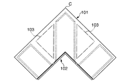
従来より、キッチン等において、特許文献1に開示されるタイプのキャビネットが利用されている。同文献のキャビネットは、図27に示されるように、平面視で屈曲形状をなすコーナーCを備えたキャビネット本体101と、このキャビネット本体101のコーナーCの前方に引き出し可能なコーナー引き出し102とを備えて構成されている。このような構成では、キャビネット本体101の内部におけるコーナー引き出し102の左右両側領域(図27中二点鎖線で示す領域)がデッドスペース103になるという問題がある。そこで、前記デッドスペース103の問題を解消するものとして、例えば、特許文献2に開示されるタイプのものがある。
Conventionally, the type of cabinet disclosed in Patent Document 1 has been used in kitchens and the like. As shown in FIG. 27 , the cabinet of the same document includes a
特許文献2において、キャビネット本体のコーナーには、床面上を転動するキャスター付きのワゴンが配置され、当該ワゴンの左右両側領域には、コーナー前方にスライド移動可能な収納ラックがそれぞれ設けられている。このような構成によれば、ワゴン及び各収納ラックに収納対象物を収納可能となり、図27のようなデッドスペース103が生じることが回避される。
In
しかしながら、特許文献2の構成にあっては、キャスターだけによってワゴンをスライド移動するため、当該スライド移動時にキャスターの向きが変わってワゴンが蛇行する等、ワゴンの移動軌跡にばらつきが生じ易くなる。このため、ワゴンをキャビネット本体内に押し戻したときに、ワゴンの前面板と隣り合う引き出し等の前面板とが干渉したり、それら前面板が面一に揃い難くなるという不都合を生じる。
また、収納ラックを出し入れする場合、特許文献2の図2及び図4(b)に示されるように、ワゴンと収納ラックとの干渉を回避すべく、コーナー前方から離れた場所にワゴンを移動させる作業が不可避となる。この作業は、ワゴンが他の引き出しの前面板等にぶつからないように行う必要があるため、時間を要するばかりでなく使用者に手間を強いるという不都合もある。
特に、キャビネット本体を平面視コ字状となる屈曲形状にする等、コーナー前方の作業領域が狭くなると、ワゴンをコーナーから離れた場所に移動する途中でワゴンが他の引き出しの前面板等に接触し易くなるため、ワゴンの移動作業がより煩雑になるという不都合を招来する。
However, in the configuration of
When the storage rack is taken in and out, as shown in FIGS. 2 and 4B of
In particular, when the work area in front of the corner becomes narrow, such as when the cabinet body is bent in a U shape in plan view, the wagon contacts the front plate of other drawers while moving the wagon away from the corner. As a result, the moving operation of the wagon becomes more complicated.
[発明の目的]
本発明は、このような不都合に着目して案出されたものであり、その目的は、コーナー引き出しの移動軌跡を安定させつつ、コーナー引き出しの側方のスペースを有効に利用でき、当該スペースへの収納対象物の出し入れを容易に行うことができる家具を提供することにある。
[Object of invention]
The present invention has been devised by paying attention to such inconveniences, and the purpose thereof is to stabilize the movement path of the corner drawer and to effectively use the space on the side of the corner drawer. An object of the present invention is to provide a furniture that can easily take in and out a storage object.
前記目的を達成するため、本発明は、平面視で屈曲若しくは湾曲形状をなすコーナーを含む家具本体と、前記コーナーに配置されるとともに、スライダを介して家具本体から出し入れ可能に設けられたコーナー引き出しと、このコーナー引き出しの少なくとも一方の側方に配置されるとともに、所定の収納対象物を収納可能なスペース利用部材とを備え、
前記コーナー引き出しは、家具本体のコーナー前方に配置される前部材と、この前部材の後方に連設されるとともに、内部に収納空間を有する収納体とを含み、
前記スペース利用部材は、前記コーナー引き出しを引き出したときに、家具本体の前方からアクセス可能な位置に移動可能に設けられているとともに、前記スペース利用部材は、前記収納体の高さ領域と異なる高さ領域であって、前部材の高さ領域内に設けられる、という構成を採っている。
In order to achieve the above object, the present invention provides a furniture body including a corner that is bent or curved in plan view, and a corner drawer that is disposed at the corner and is detachable from the furniture body via a slider. And a space utilization member that is disposed on at least one side of the corner drawer and can store a predetermined storage object,
The corner drawer includes a front member disposed in front of the corner of the furniture body, and a storage body continuously provided behind the front member and having a storage space therein.
The space utilization member is provided so as to be movable to a position accessible from the front of the furniture body when the corner drawer is pulled out, and the space utilization member has a height different from the height region of the storage body. a is the area, Ru provided in front member height region, it adopts a configuration that.
本発明において、前記スペース利用部材は、前記コーナー引き出しを引き出したときに、収納体の上方に移動可能に設けられる、という構成を採用することができる。 In the present invention, it is possible to adopt a configuration in which the space utilization member is provided movably above the storage body when the corner drawer is pulled out .
更に、前記家具本体は、スペース利用部材の移動方向に沿う起立面部を含み、
前記スペース利用部材は、起立面部との間に設けられた移動部材を介して移動可能に設けられる、という構成も採ることができる。
Furthermore, the furniture body includes an upright surface along the moving direction of the space utilization member,
The space utilization member can also be configured to be movable via a moving member provided between the upright surface portion.
また、前記家具本体は、スペース利用部材の下側に配置された支持面部を含み、
前記スペース利用部材は、支持面部との間に設けられた移動部材を介して移動可能に設けられている、という構成を採ることが好ましい。
In addition, the furniture body includes a support surface portion disposed below the space utilization member,
It is preferable that the space utilization member is configured to be movable through a moving member provided between the space utilization member and the support surface portion.
更に、前記スペース利用部材は、前記家具本体に回動手段を介して回動可能に支持される、という構成を採用するとよい。 Furthermore, it is preferable to adopt a configuration in which the space utilization member is rotatably supported by the furniture body via a rotation means.
また、前記回動手段とスペース利用部材との間にスライド手段を設け、当該スライド手段を介してスペース利用部材をコーナー前方に移動可能に設ける、という構成を採用することもできる。 Further, it is also possible to adopt a configuration in which a slide means is provided between the rotating means and the space utilization member, and the space utilization member is provided so as to be movable forward of the corner via the slide means.
更に、前記スペース利用部材は、移動部材を介して移動可能に設けられ、この移動部材は、前記コーナー引き出しを引き出す移動により、スペース利用部材を初期位置からコーナー前方に移動させる一方、コーナー引き出しを押し戻す移動により、スペース利用部材を初期位置側に移動させる、という構成も好ましくは採用される。 Furthermore, the space utilization member is provided so as to be movable via a moving member, and the movement member moves the space utilization member from the initial position to the front of the corner by pushing out the corner drawer, and pushes back the corner drawer. A configuration in which the space utilization member is moved to the initial position side by movement is also preferably employed.
また、前記スペース利用部材とコーナー引き出しとは連結部材により連結されている一方、コーナー引き出しを回転させるヒンジ部材を設け、
前記連結部材は、コーナー引き出しの前記回転により、スペース利用部材を初期位置とコーナー前方との間で移動可能に設ける、という構成も採ることができる。
The space utilization member and the corner drawer are connected by a connecting member, while a hinge member for rotating the corner drawer is provided,
The connecting member can also be configured such that the space utilization member is movably provided between the initial position and the corner front by the rotation of the corner drawer.
更に、前記スペース利用部材は、移動部材を介して移動可能に設けられ、この移動部材は、コーナー引き出しの引き出し方向に沿ってスペース利用部材を移動させる第1のスライド手段と、前記引き出し方向と平面視で交わる方向にスペース利用部材を移動させる第2のスライド手段とを備える、という構成を採用するとよい。 Further, the space utilization member is provided so as to be movable via a moving member, and the movement member includes a first slide means for moving the space utilization member along a pulling direction of the corner drawer, and the pulling direction and the plane. It is good to employ | adopt the structure provided with the 2nd slide means to which a space utilization member is moved to the direction which cross | intersects visually.
本発明によれば、スライダを介してコーナー引き出しを安定した軌跡に沿って移動することができる。これにより、従来のワゴンのように移動軌跡にばらつきが生じることを回避でき、隣り合う引き出しと位置的に不揃いになることを防止することが可能となる。また、コーナー引き出しの側方領域にスペース利用部材を設けたので、当該側方領域を有効利用して収納空間の拡大化を図ることができる。しかも、コーナー引き出しを引き出した状態で、スペース利用部材が家具本体前方からアクセス可能な位置に移動し、スペース利用部材への収納対象物の出し入れを行うことができる。これにより、従来のように、コーナーから離れた位置にワゴンを移動させる作業を省略でき、家具本体の前面側の損傷を防止できる他、収納対象物の出し入れも迅速且つ容易に行うことが可能となる。
ここで、コーナー引き出しの収納体と異なる高さ領域にスペース利用部材を設けた場合には、収納体とスペース利用部材とを上下に重なるように位置させることができる。これにより、例えば、コーナー引き出しを引き出した状態で、収納体の上方であって家具本体の前部より手前側にスペース利用部材を移動できるようになり、当該スペース利用部材への収納対象物の出し入れをより楽に行うことが可能となる。
また、前述の各種部材を介してスペース利用部材を移動させることにより、コーナー引き出し及び家具本体のサイズや形状に応じて、スペース利用部材に収納対象物を出し入れし易いような設計を採用することが可能となる。
According to the present invention, the corner drawer can be moved along a stable locus via the slider. As a result, it is possible to avoid variations in the movement trajectory as in the case of a conventional wagon, and it is possible to prevent positional deviation from adjacent drawers. In addition, since the space utilization member is provided in the side region of the corner drawer, the storage space can be expanded by effectively utilizing the side region. In addition, with the corner drawer pulled out, the space utilization member moves to a position accessible from the front of the furniture body, and the storage object can be taken in and out of the space utilization member. As a result, the work of moving the wagon to a position away from the corner as in the prior art can be omitted, damage to the front side of the furniture body can be prevented, and storage objects can be taken in and out quickly and easily. Become.
Here, when the space utilization member is provided in a height region different from the corner drawer storage body, the storage body and the space utilization member can be positioned so as to overlap vertically. Thereby, for example, with the corner drawer pulled out, the space utilization member can be moved to the front side from the front part of the furniture body above the storage body, and the storage object can be taken in and out of the space utilization member. Can be performed more easily .
In addition, by moving the space utilization member via the various members described above, it is possible to adopt a design that makes it easy to put objects into and out of the space utilization member according to the size and shape of the corner drawer and the furniture body. It becomes possible.
以下、本発明の好ましい実施の形態について図面を参照しながら説明する。
なお、本明細書及び特許請求の範囲における方向若しくは位置を示す用語は、コーナーの入隅側を正面視した場合すなわち図1中矢印A方向から見た場合を基準とし、「前」とは、矢印A方向から見た場合の手前側を示す一方、「後」とは、同奥行き側について用いられる。
また、「スライダ」とは、被移動対象物の移動方向に沿って延びる部材を含み、意図的な操作を行わない限り、略一定の軌跡に沿って被移動対象物を移動させるものである。
Hereinafter, preferred embodiments of the present invention will be described with reference to the drawings.
In addition, the term indicating the direction or position in the present specification and claims is based on the front view of the entrance corner side of the corner, that is, when viewed from the direction of arrow A in FIG. While the front side when viewed from the direction of arrow A is shown, “rear” is used for the same depth side.
The “slider” includes a member extending along the moving direction of the object to be moved, and moves the object to be moved along a substantially constant trajectory unless an intentional operation is performed.
[第1実施形態]
図1には、第1実施形態に係るキャビネットの概略斜視図が示されている。この図において、家具としてのキャビネット10は、特に限定されるものでないが、本実施形態では、キッチン用のキャビネットとして用いられる。このキャビネット10は、平面視で略L字状の屈曲形状をなすコーナーCを含む家具本体としてのキャビネット本体11と、このキャビネット本体11のコーナーCに配置された上下二段のコーナー引き出し12,12と、これらコーナー引き出し12,12の左右両側にそれぞれ設けられた複数のサイド引き出し13とを備えて構成されている。
[First Embodiment]
FIG. 1 is a schematic perspective view of a cabinet according to the first embodiment. In this figure, the cabinet 10 as furniture is not particularly limited, but is used as a kitchen cabinet in the present embodiment. The cabinet 10 includes a
前記キャビネット本体11は、略L字状の平面形状に設けられた天板15と、この天板15の図1中左右両側における下方位置に設けられるとともに、前記サイド引き出し13,13を収容する一対のサイド箱体16,16と、各サイド箱体16,16の間であって前記コーナーCに位置するとともに、コーナー引き出し12,12を収容するコーナー箱体17とを備えて構成されている。
The
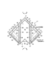
前記コーナー箱体17は、図2及び図3に示されるように、上下方向に沿ってそれぞれ延びるとともに、前方に向かうに従って次第に接近する左右一対の側板20,20と、これら側板20,20の後端側にそれぞれ位置するとともに、コーナーC後部において平面視略直角に連結される左右一対の背板21,21と、各側板20,20の上部前端側にそれぞれ連結される左右一対の前板22,22及び下部前端側にそれぞれ連結される左右一対の蹴込み板23,23と、当該蹴込み板23,23の上端側に位置する底板25と、この底板25から上方に延びて前後方向に向けられるとともに、コーナー引き出し12の左右両側に位置する一対の仕切板26,26とを備えて構成されている。
As shown in FIGS. 2 and 3, the
側板20,20の前端、前板22,22及び蹴込み板23,23の間には、コーナー引き出し12により閉塞される開口部27が形成される。右側の前板22は、その後端が左側の背板21に連結されるとともに、延出方向中間部において渡設板29を介して右側の背板21に連結される。各仕切板26,26の前端側及び後端側は、隣接する側板20,20若しくは背板21,21に連結板30を介してそれぞれ連結されている。
Between the front ends of the
図1及び2に示されるように、前記上段のコーナー引き出し12より下段のコーナー引き出し12の方が、前部材としての前板32の上下高さが大きく形成されている。各コーナー引き出し12は、図3ないし図5に示されるように、コーナーC前方に配置され、天板15のコーナーCにおける前端に沿って平面視略L字状をなす前記前板32と、この前板32の後方に連設されるとともに、上方を開放して内部に収納空間33を有する収納体34と、前板33の前面に取り付けられた把手35とを備えて構成されている。上段のコーナー引き出し12は、前板32の上下高さが収納体34の上下高さより若干大きく形成されている。一方、下段のコーナー引き出し12は、前板32の上下高さが収納体34の上下高さの約3倍以上となるように形成されている。
As shown in FIGS. 1 and 2, the
前記収納体34は、前板32と略平行に配置されて当該前板32と同様に平面視略L字状に形成された背板37と、前板32と背板37との間に設けられた一対の側板38,38と、前板32、背板37及び各側板38,38の下部間に位置する底板39とを備えて構成されている。側板38,38と前記仕切板26,26との間には、スライダ41,41が設けられ、当該スライダ41,41を介してコーナー引き出し12を前後方向(図3中上下方向)に沿って出し入れできるようになっている。ここで、図3に示されるように、コーナー引き出し12の側方すなわち左右両側には、スペース利用部材43,43がそれぞれ配置されている。
The
前記各スペース利用部材43,43は、側板20,背板21及び仕切板26で囲まれる領域に配置されている。スペース利用部材43は、平面視で略直角二等辺三角形状に形成された底部材45と、この底部材45の側板20,背板21及び仕切板26に沿う端部側から立設された第1ないし第3の側部材46〜48とを備え、所定の収納対象物を収納可能な有底容器状に形成されている。側板20及びこれに沿う第1の側部材46の間には、移動部材としてのスライダ50が設けられている。スペース利用部材43は、スライダ50を介して側板20の内面に片持ち支持され、且つ、コーナーC前方にスライド移動できるようになっている(図7参照)。ここにおいて、側板20の内面がスペース利用部材43の移動方向に沿う起立面部とされる。
The
図4ないし図6に示されるように、各スペース利用部材43,43は、上下のコーナー引き出し12,12の収納体34の高さ領域と異なる高さ領域であって、下段のコーナー引き出し12の前板32の高さ領域内に設けられている。具体的には、図3中左側すなわち図4に示されるスペース利用部材43は、その上端位置が下段のコーナー引き出し12における前板32の上端より若干低い位置に設定されている。一方、図3中右側すなわち図5に示されるスペース利用部材43は、その下端位置が下段のコーナー引き出し12における収納体34の上端より若干高い位置に設定され、且つ、その上端位置が左側のスペース利用部材43の下端位置より低い位置(図6参照)に設定されている。
As shown in FIGS. 4 to 6, each
なお、図4及び図5に示されるように、各仕切板26,26において、スペース利用部材43,43の第3の側部材48に対向する領域には開放部51が形成され、当該開放部51を通過して各スペース利用部材43,43がコーナーC前方に移動できるようになっている。
As shown in FIGS. 4 and 5, in each
以上の構成において、スペース利用部材43,43に収納対象物を出し入れする場合、図7に示されるように、下段のコーナー引き出し12を前方に引き出した後、スペース利用部材43をコーナーC前方(同図中二点鎖線で示される方向)に引き出せばよい。この際、各スペース利用部材43,43及び収納体34は、前述した高さ領域に設けられるため、それらが相互に干渉することなく引き出すことができる。この状態で、スペース利用部材43,43は、前記開口部27に跨るようになり、使用者によりアクセス可能な位置、すなわち、収納対象物の出し入れを行える位置に移動することとなる。
In the above configuration, when the object to be stored is taken in and out of the
従って、このような第1実施形態によれば、コーナー引き出し12を前記スライダ41によって安定して移動できる他、相互に高さ領域が異なる左右一対のスペース利用部材43,43を設けたので、キャビネット本体11内におけるコーナー引き出し12の左右両側に収納対象物を収納することが可能となる。また、前方に引き出された下段のコーナー引き出し12における収納体34の上方に、各スペース利用部材43,43を配置することができ、その内部に収納対象物の出し入れを容易且つ迅速に行えるという効果を得る。
Therefore, according to the first embodiment, the
次に、本発明の第1実施形態以外の実施形態について説明する。なお、以下の説明において、前記第1実施形態と同一若しくは同等の構成部分については必要に応じて同一符号を用いるものとし、説明を省略若しくは簡略にする。 Next, embodiments other than the first embodiment of the present invention will be described. In the following description, the same or equivalent components as those in the first embodiment are denoted by the same reference numerals as necessary, and the description is omitted or simplified.
[第2実施形態]
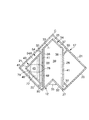
図8ないし図11には、本発明のキャビネットに係る第2実施形態が示されている。この第2実施形態は、各スペース利用部材43,43を下側から支持してスライド移動可能としたものである。各スペース利用部材43,43の下側には、略水平方向に向けられた支持板54,54がそれぞれ設けられ、各支持板54,54は、側板20、背板21及び仕切板26の各内面により支持されている。支持板54の上面は支持面部54Aとされ、当該支持面部54Aとスペース利用部材43における底部材45の下面との間に移動部材としてのスライダ55が設けられている。スライダ55は、スペース利用部材43毎に二本ずつ設けられるとともに、スペース利用部材43の移動方向に沿って伸縮自在とされている。これにより、図11に示されるように、第1実施形態と同様にしてスペース利用部材43をコーナーC前方に引き出し移動することができ、この状態で、スペース利用部材43にアクセスして収納対象物の出し入れを行えるようになっている。
[Second Embodiment]
8 to 11 show a second embodiment according to the cabinet of the present invention. In the second embodiment, the
従って、このような第2実施形態によれば、第1実施形態と同様の効果が得られる他、スライダ55及び支持板54を介してスペース利用部材43を下側からしっかりと支持することができる。
Therefore, according to the second embodiment, the same effect as that of the first embodiment can be obtained, and the
[第3実施形態]
図12には、本発明のキャビネットに係る第3実施形態が示されている。この第3実施形態は、各スペース利用部材43,43を回動可能に設けたものである。各スペース利用部材43,43は、第1及び第3の側部材46,48の連結位置において、回動手段としてのヒンジ58を介して側板20の内面に支持されている。これにより、スペース利用部材43は、ヒンジ58を中心位置として回動させることにより、図12中二点鎖線で示す位置を通ってコーナーC前方に移動可能となり、その内部に容易にアクセス可能となる。なお、各スペース利用部材43,43の第3の側部材48は、第1の側部材46と略同一長さとされ、前記回動時に仕切板26に干渉しないようになっている。
[Third Embodiment]
FIG. 12 shows a third embodiment according to the cabinet of the present invention. In the third embodiment, the
[第4実施形態]
図13及び図14には、本発明のキャビネットに係る第4実施形態が示されている。この第4実施形態は、各スペース利用部材43,43を回動可能とし、且つ、前後方向にスライド移動可能に設けたものである。
図13に示されるように、各スペース利用部材43,43は、平面視で略半円状に形成された底部材60と、この底部材60の仕切板26側の端部から立設された側部材61と、底部材60の円弧状端部から立設された湾曲側部材62とを備えている。側部材61には、その外面に沿ってスライド手段としてのスライダ64が設けられ、このスライダ64に連結バー65を介して回動手段としてのヒンジ66が連結されている。ヒンジは、底板25に立設されるとともに、上部側で連結バー65を支持している。
[Fourth Embodiment]
13 and 14 show a fourth embodiment according to the cabinet of the present invention. In the fourth embodiment, the
As shown in FIG. 13, each
以上の構成において、スペース利用部材43,43を利用する場合、コーナー引き出し12を前方に引き出した後、ヒンジ66を中心位置としてスペース利用部材43を図13に示される位置から図14に示される位置に回動させる。その後、側部材61が前後方向に向けられた状態で、スライダ64を介してスペース利用部材43をコーナーC前方に移動させることにより、前記開口部27にスペース利用部材43が跨るようになる。
In the above configuration, when using the
従って、このような第4実施形態によれば、前記第1実施形態と同様の効果が得られるばかりでなく、側板20と背板21との連結部分付近と開口部27に跨る位置との間でスペース利用部材43を移動させることができる。
Therefore, according to such a fourth embodiment, not only the same effects as in the first embodiment can be obtained, but also between the vicinity of the connection portion between the
[第5実施形態]
図15ないし図17には、本発明のキャビネットに係る第5実施形態が示されている。この第5実施形態は、コーナー引き出し12の出し入れ移動に伴ってスペース利用部材43を移動可能としたものである。
同実施形態において、スペース利用部材43は、コーナー引き出し12の左側だけに配置され、前記第2実施形態と同様に、支持面部54Aとの間に設けられた二本のスライダ55を介してスライド移動可能に設けられている。スペース利用部材43の底側には、コーナー引き出し12の収納体34側に延びる長片板状の突出部材68が設けられ、この突出部材68の先端上面側にローラ69(図16(B)参照)が支持されている。
また、収納体34の上方位置には、下方を開放するCチャンネル状のレール70が設けられ、このレール70は、収納体34における左側の側板38の前端側から右側の側板38の後端側を掛け渡すように配置されている。レール70は、その内部にローラ69を受容しつつ、延出方向に沿ってローラ69を移動させるようになっている。ここにおいて、スライダ55、突出部材68、ローラ69及びレール70により移動部材が構成される。
[Fifth Embodiment]
15 to 17 show a fifth embodiment according to the cabinet of the present invention. In the fifth embodiment, the
In the embodiment, the
In addition, a C-
以上の構成において、スペース利用部材43にアクセスする場合、コーナー引き出し12を前方に引き出せばよい。これにより、ローラ69がレール70における左側の側板38の前端側から右側の側板38の後端側へスライドし、ローラ69が図15中右下方向に移動する。この移動によってスペース利用部材43が図15の初期位置からコーナーC前方に移動し、図17に示される状態となり、スペース利用部材43内に使用者がアクセス可能となる。
一方、この状態から、コーナー引き出し12を後方に押し戻すと、前述と逆の要領により、ローラ69及びレール70を介してスペース利用部材43が前記初期位置に向かって移動し、図15に示される状態とすることができる。
In the above configuration, when accessing the
On the other hand, when the
従って、このような第5実施形態によれば、コーナー引き出し12の出し入れ移動を行うことにより、スペース利用部材43を直接操作することなく出し入れすることができ、スペース利用部材43の取扱性をより向上させることが可能となる。
Therefore, according to the fifth embodiment as described above, by moving the
[第6実施形態]
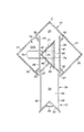
図18ないし図20には、本発明のキャビネットに係る第6実施形態が示されている。この第6実施形態は、コーナー引き出し12を前方に引き出した状態で回転可能に設け、当該回転によりスペース利用部材43を移動可能としたものである。
同実施形態において、スペース利用部材43は、前記第5実施形態と同様に配置されてスライド移動可能に設けられている。また、スペース利用部材43に対し、第5実施形態と略同構造の突出部材68に下向きとなるローラ69が設けられている。
収納体34の左側の側板38には、前後方向に延びるスライダ72が設けられている一方、左側の側板20の前方内面側には、ヒンジ部材73が設けられている。このヒンジ部材73は、前記スライダ72を介してコーナー引き出し12を片持ち支持するとともに、スライダ72を前後方向に案内可能に設けられている。ヒンジ部材73は、コーナー引き出し12を引き出し限まで引き出したときに、コーナー引き出し12を平面視で時計方向に回転させる(図19及び図20参照)。ヒンジ部材73には、前後方向に延びるレール74が設けられ、このレール74は、上方を開放するCチャンネル状に設けられて前記ローラ69を受容するようになっている。ここにおいて、突出部材68、ローラ69及びレール74により連結部材が構成される。
[Sixth Embodiment]
18 to 20 show a sixth embodiment according to the cabinet of the present invention. In the sixth embodiment, the
In the same embodiment, the
A
以上の構成において、図19及び図20に示されるように、コーナー引き出し12を引き出し限まで引き出した後、ヒンジ部材73を中心として時計方向に回転させると、ローラ69がレール70の前側にややスライドしつつ図中右下方向に移動する。これにより、スペース利用部材43が図19の初期位置からコーナーC前方に移動し、スペース利用部材43内にアクセス可能となる(図20参照)。
一方、この状態から、反時計方向にコーナー引き出し12を回転させることにより、前述と逆の要領によってローラ69が移動し、スペース利用部材43を前記初期位置に向かって移動させることができる。
In the above configuration, as shown in FIGS. 19 and 20, when the
On the other hand, by rotating the
従って、このような第6実施形態によれば、コーナー引き出し12の回転操作によってスペース利用部材43の出し入れ移動を行うことが可能となる。
Therefore, according to the sixth embodiment, it is possible to move the
[第7実施形態]
図21ないし図23には、本発明のキャビネットに係る第7実施形態が示されている。この第7実施形態は、平面視で略直交する方向に向けられた第1及び第2のスライド手段77,78を介してスペース利用部材43を移動可能としたものである。
第1のスライド手段77は、前後方向に向けられた伸縮自在な二本のスライダにより構成され、スペース利用部材43における底部材45の下面に取り付けられている。一方、第2のスライド手段78は、左右方向に向けられた伸縮自在な二本のスライダにより構成され、前記支持面部54Aに取り付けられている。第1及び第2のスライド手段77,78は、底部材45と略相似形の中間板79を介して連結されている。
[Seventh Embodiment]
21 to 23 show a seventh embodiment according to the cabinet of the present invention. In the seventh embodiment, the
The first slide means 77 is composed of two stretchable sliders oriented in the front-rear direction, and is attached to the lower surface of the
以上の構成において、スペース利用部材43にアクセスする場合、先ず、図22に示されるように、コーナー引き出し12を引き出した後、第2のスライド手段78を介してスペース利用部材43及び中間板79を右方向に移動する。そして、コーナー引き出し12の後方までスペース利用部材43を移動させた後、第2のスライド手段78を介してスペース利用部材43をコーナーC前方に引き出すことにより、スペース利用部材43が開口部27に跨るように位置することとなる。
In the above configuration, when accessing the
従って、このような第7実施形態によれば、スペース利用部材43を平面視で二つの異なる方向に移動させて当該スペース利用部材43の出し入れを行うことができる。
Therefore, according to the seventh embodiment, the
[第8実施形態]
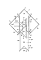
図24ないし図26には、本発明のキャビネットに係る第8実施形態が示されている。この第8実施形態は、第3実施形態の左側のスペース利用部材43を、コーナー引き出し12の出し入れ移動に伴って移動可能としたものである。
同実施形態において、スペース利用部材43及び下段のコーナー引き出し12の各後側には、紐状若しくは帯状の連結体90が取り付けられている。この連結体90は、その一端側がスペース利用部材43における第1の側部材46の後端側に接続されている一方、他端側が収納体34における背板37の左右方向中央部に接続されている。連結体90は、コーナー引き出し12の後方における底板25上に設けられたローラ91に掛け回されている。
図26に示されるように、スペース利用部材43における第3の側部材48の下部には、底部材45より下方に延びる垂下面部92が連設されている。この垂下面部92は、収納体34における背板37と左側の側板38との間のコーナー部に当接するように設けられている。ここにおいて、ヒンジ58、連結体90、ローラ91及び垂下面部92により移動部材が構成される。
なお、下段のコーナー引き出し12は、その背板37が各側板38,38に直交して左右方向に沿う形状とされ、一対のスライダ86,86を介して前後にスライド移動可能とされる。
[ Eighth Embodiment]
24 to 26 show an eighth embodiment according to the cabinet of the present invention. In the eighth embodiment, the
In the embodiment, a string-like or belt-like connecting
As shown in FIG. 26 , a drooping
Note that the
以上の構成において、コーナー引き出し12を前方に引き出すことにより、連結体90がスペース利用部材43を図24中右上方向に引っ張られ、時計方向に回転することとなる。これにより、スペース利用部材43が図29の初期位置から収納体34の後方に移動し、当該スペース利用部材43にアクセス可能な状態となる(図25参照)。
一方、この状態から、コーナー引き出し12を後方に押し戻すと、収納体34の後部コーナー領域により垂下面部92を後方に押圧し、スペース利用部材43が反時計方向に回転して前記初期位置に復帰する。
In the above configuration, by pulling out the
On the other hand, when the
従って、このような第8実施形態によれば、コーナー引き出し12の出し入れ移動を
行うことにより、スペース利用部材43を直接操作することなく回転移動させることがで
きる。
Therefore, according to such an eighth embodiment, by moving the
本発明を実施するための最良の構成、方法などは、以上の記載で開示されているが、本発明は、これに限定されるものではない。
すなわち、本発明は、特定の実施の形態に関して特に図示し、且つ、説明されているが、本発明の技術的思想及び目的の範囲から逸脱することなく、以上に述べた実施例に対し、形状、位置若しくは方向、その他の詳細な構成において、当業者が様々な変形を加えることができるものである。
従って、上記に開示した形状などを限定した記載は、本発明の理解を容易にするために例示的に記載したものであり、本発明を限定するものではないから、それらの形状などの限定の一部若しくは全部の限定を外した部材の名称での記載は、本発明に含まれるものである。
The best configuration, method and the like for carrying out the present invention have been disclosed in the above description, but the present invention is not limited to this.
That is, the present invention has been particularly shown and described with respect to particular embodiments, but is not limited to the embodiments described above without departing from the scope and spirit of the present invention. Various modifications may be made by those skilled in the art in terms of position, orientation, and other detailed configurations.
Therefore, the description limited to the shape disclosed above is an example for easy understanding of the present invention, and does not limit the present invention. The description by the name of the member which remove | excluded one part or all part is included in this invention.
例えば、キャビネット本体11は、種々の設計変更が可能であり、例えば、コーナーCを平面視で略円弧状をなす湾曲形状に形成したり、コーナーCを二つ含む平面視略コ字状に形成してもよい。
また、コーナー引き出し12の左右両側に設けたスペース利用部材43,43の何れか一方を省略した構成としたり、スペース利用部材43を網籠状に形成してもよく、更には、第5〜第7実施形態、第8実施形態のように左右何れか一方にのみスペース利用部材43を設ける場合には、他方側に適宜着脱自在或いは固定式の棚板等を設ける構成としてもよい。また、上記各実施形態をコーナー引き出し12の左右両側において適宜違う形態を採用して組合せることも勿論可能であり、使用者の幅広いニーズに柔軟に対応することができるキャビネットを提供することができる。
更に、前記各実施形態において、スペース利用部材43を移動させる移動部材やスライド手段をスライダ50,55,64としたり、回動手段をヒンジ58,66としたりしたが、各実施形態で述べた作用と同様の作用を奏する限りにおいて、種々の設計変更が可能である。
更に、本発明は、キッチンに配置されるキャビネット10に限られず、リビングに配置されるコーナー家具等の種々の家具に適用することができる。
For example, the
Further, either one of the
Further, in the above described embodiments, or the moving member or slide means for moving the
Furthermore, the present invention is not limited to the cabinet 10 disposed in the kitchen, and can be applied to various furniture such as corner furniture disposed in the living room.
本発明は、主に、キッチン等の室内空間におけるコーナー部に配置される家具に利用することができる。 INDUSTRIAL APPLICATION This invention can be mainly utilized for the furniture arrange | positioned in the corner part in indoor space, such as a kitchen.
10・・・キャビネット(家具)、11・・・キャビネット本体(家具本体)、12・・・コーナー引き出し、20・・・側板、32・・・前板(前部材)、32・・・収納空間、34・・・収納体、41・・・スライダ、43・・・スペース利用部材、50・・・スライダ(移動部材)、54A・・・支持面部、55・・・スライダ(移動部材)、58・・・ヒンジ(回動手段)、64・・・スライダ(スライド手段)、66・・・ヒンジ(回動手段)、73・・・ヒンジ部材、77・・・第1のスライド手段、78・・・第2のスライド手段、C・・・コーナー
DESCRIPTION OF SYMBOLS 10 ... Cabinet (furniture), 11 ... Cabinet main body (furniture main body), 12 ... Corner drawer, 20 ... Side plate, 32 ... Front plate (front member), 32 ...
Claims (9)
前記コーナー引き出しは、家具本体のコーナー前方に配置される前部材と、この前部材の後方に連設されるとともに、内部に収納空間を有する収納体とを含み、
前記スペース利用部材は、前記コーナー引き出しを引き出したときに、家具本体の前方からアクセス可能な位置に移動可能に設けられているとともに、前記スペース利用部材は、前記収納体の高さ領域と異なる高さ領域であって、前部材の高さ領域内に設けられていることを特徴とする家具。 A furniture body including a corner that is bent or curved in plan view, a corner drawer that is disposed in the corner and is detachable from the furniture body via a slider, and at least one side of the corner drawer And a space utilization member capable of storing a predetermined storage object,
The corner drawer includes a front member disposed in front of the corner of the furniture body, and a storage body continuously provided behind the front member and having a storage space therein.
The space utilization member is provided so as to be movable to a position accessible from the front of the furniture body when the corner drawer is pulled out, and the space utilization member has a height different from the height region of the storage body. The furniture is characterized by being provided in the height region of the front member .
前記スペース利用部材は、起立面部との間に設けられた移動部材を介して移動可能に設けられていることを特徴とする請求項1又は2記載の家具。 The furniture body includes an upright surface along the moving direction of the space utilization member,
The furniture according to claim 1 or 2 , wherein the space utilization member is provided so as to be movable via a moving member provided between the upright surface portion.
前記スペース利用部材は、支持面部との間に設けられた移動部材を介して移動可能に設けられていることを特徴とする請求項1又は2記載の家具。 The furniture body includes a support surface portion disposed on the lower side of the space utilization member,
The space utilization member, furniture according to claim 1 or 2, characterized in that provided movably via a movable member provided between the support surface.
前記連結部材は、コーナー引き出しの前記回転により、スペース利用部材を初期位置とコーナー前方との間で移動可能に設けたことを特徴とする請求項1又は2記載の家具。 While the space utilization member and the corner drawer are connected by a connecting member, a hinge member for rotating the corner drawer is provided,
The furniture according to claim 1 or 2 , wherein the connecting member is provided such that the space utilization member can be moved between the initial position and the front of the corner by the rotation of the corner drawer.
Priority Applications (1)
| Application Number | Priority Date | Filing Date | Title |
|---|---|---|---|
| JP2004249834A JP4510552B2 (en) | 2004-08-30 | 2004-08-30 | furniture |
Applications Claiming Priority (1)
| Application Number | Priority Date | Filing Date | Title |
|---|---|---|---|
| JP2004249834A JP4510552B2 (en) | 2004-08-30 | 2004-08-30 | furniture |
Publications (2)
| Publication Number | Publication Date |
|---|---|
| JP2006061548A JP2006061548A (en) | 2006-03-09 |
| JP4510552B2 true JP4510552B2 (en) | 2010-07-28 |
Family
ID=36108506
Family Applications (1)
| Application Number | Title | Priority Date | Filing Date |
|---|---|---|---|
| JP2004249834A Expired - Fee Related JP4510552B2 (en) | 2004-08-30 | 2004-08-30 | furniture |
Country Status (1)
| Country | Link |
|---|---|
| JP (1) | JP4510552B2 (en) |
Family Cites Families (9)
| Publication number | Priority date | Publication date | Assignee | Title |
|---|---|---|---|---|
| JPS58190406A (en) * | 1982-04-30 | 1983-11-07 | 松下電工株式会社 | Accommodating furniture |
| JPH026836Y2 (en) * | 1986-01-29 | 1990-02-19 | ||
| JPH0313839U (en) * | 1989-06-27 | 1991-02-13 | ||
| JPH06327518A (en) * | 1993-05-27 | 1994-11-29 | Matsushita Electric Works Ltd | Cabinet |
| JP2828957B2 (en) * | 1996-09-04 | 1998-11-25 | 高橋金物株式会社 | Corner storage cabinet |
| JP2000308535A (en) * | 1999-04-28 | 2000-11-07 | Yamaha Livingtec Corp | Housing device of corner part cabinet of kitchen |
| JP4312935B2 (en) * | 2000-07-14 | 2009-08-12 | クリナップ株式会社 | Kitchen corner storage device |
| JP2002153338A (en) * | 2000-11-22 | 2002-05-28 | Matsushita Electric Works Ltd | Floor stoker for system kitchen |
| JP4778169B2 (en) * | 2001-08-31 | 2011-09-21 | クリナップ株式会社 | Corner cabinet |
-
2004
- 2004-08-30 JP JP2004249834A patent/JP4510552B2/en not_active Expired - Fee Related
Also Published As
| Publication number | Publication date |
|---|---|
| JP2006061548A (en) | 2006-03-09 |
Similar Documents
| Publication | Publication Date | Title |
|---|---|---|
| US9872562B2 (en) | Cabinet | |
| JP4510552B2 (en) | furniture | |
| JP4216771B2 (en) | building | |
| US20140346934A1 (en) | Adjustable Storage System | |
| JP2005296085A (en) | Storage device | |
| JP3178672U (en) | Folding desk | |
| JP2017196261A (en) | Cabinet with table | |
| JP2017038655A (en) | Option fitting structure | |
| JPH0618520Y2 (en) | Storage device | |
| JP6865588B2 (en) | Corner cabinet | |
| JP6589455B2 (en) | Medical wagon | |
| JP5965303B2 (en) | Cabinet and storage unit | |
| JP3583316B2 (en) | basket | |
| JP6751334B2 (en) | Wagon equipment | |
| JP7788268B2 (en) | Shopping Cart | |
| JP3186800U (en) | wagon | |
| JP5578741B2 (en) | Kitchen cabinet drawer | |
| JP4977871B2 (en) | Furniture with a top plate | |
| JP2005270195A (en) | Storage system | |
| JP7232975B2 (en) | storage furniture | |
| JPS6326049Y2 (en) | ||
| JPH0247855Y2 (en) | ||
| JP2018183489A (en) | Combination desk | |
| JP4518476B2 (en) | cabinet | |
| JP2002112843A (en) | Bottle-housing cabinet |
Legal Events
| Date | Code | Title | Description |
|---|---|---|---|
| A621 | Written request for application examination |
Free format text: JAPANESE INTERMEDIATE CODE: A621 Effective date: 20070223 |
|
| A977 | Report on retrieval |
Free format text: JAPANESE INTERMEDIATE CODE: A971007 Effective date: 20090309 |
|
| A131 | Notification of reasons for refusal |
Free format text: JAPANESE INTERMEDIATE CODE: A131 Effective date: 20100105 |
|
| A521 | Request for written amendment filed |
Free format text: JAPANESE INTERMEDIATE CODE: A523 Effective date: 20100304 |
|
| TRDD | Decision of grant or rejection written | ||
| A01 | Written decision to grant a patent or to grant a registration (utility model) |
Free format text: JAPANESE INTERMEDIATE CODE: A01 Effective date: 20100427 |
|
| A01 | Written decision to grant a patent or to grant a registration (utility model) |
Free format text: JAPANESE INTERMEDIATE CODE: A01 |
|
| A61 | First payment of annual fees (during grant procedure) |
Free format text: JAPANESE INTERMEDIATE CODE: A61 Effective date: 20100430 |
|
| FPAY | Renewal fee payment (event date is renewal date of database) |
Free format text: PAYMENT UNTIL: 20130514 Year of fee payment: 3 |
|
| R150 | Certificate of patent or registration of utility model |
Ref document number: 4510552 Country of ref document: JP Free format text: JAPANESE INTERMEDIATE CODE: R150 Free format text: JAPANESE INTERMEDIATE CODE: R150 |
|
| FPAY | Renewal fee payment (event date is renewal date of database) |
Free format text: PAYMENT UNTIL: 20130514 Year of fee payment: 3 |
|
| FPAY | Renewal fee payment (event date is renewal date of database) |
Free format text: PAYMENT UNTIL: 20130514 Year of fee payment: 3 |
|
| FPAY | Renewal fee payment (event date is renewal date of database) |
Free format text: PAYMENT UNTIL: 20140514 Year of fee payment: 4 |
|
| R250 | Receipt of annual fees |
Free format text: JAPANESE INTERMEDIATE CODE: R250 |
|
| S111 | Request for change of ownership or part of ownership |
Free format text: JAPANESE INTERMEDIATE CODE: R313111 |
|
| R350 | Written notification of registration of transfer |
Free format text: JAPANESE INTERMEDIATE CODE: R350 |
|
| R250 | Receipt of annual fees |
Free format text: JAPANESE INTERMEDIATE CODE: R250 |
|
| R250 | Receipt of annual fees |
Free format text: JAPANESE INTERMEDIATE CODE: R250 |
|
| R250 | Receipt of annual fees |
Free format text: JAPANESE INTERMEDIATE CODE: R250 |
|
| R250 | Receipt of annual fees |
Free format text: JAPANESE INTERMEDIATE CODE: R250 |
|
| R250 | Receipt of annual fees |
Free format text: JAPANESE INTERMEDIATE CODE: R250 |
|
| R250 | Receipt of annual fees |
Free format text: JAPANESE INTERMEDIATE CODE: R250 |
|
| R250 | Receipt of annual fees |
Free format text: JAPANESE INTERMEDIATE CODE: R250 |
|
| R250 | Receipt of annual fees |
Free format text: JAPANESE INTERMEDIATE CODE: R250 |
|
| R250 | Receipt of annual fees |
Free format text: JAPANESE INTERMEDIATE CODE: R250 |
|
| LAPS | Cancellation because of no payment of annual fees |