JP4508265B2 - Electro-optical device and electronic apparatus - Google Patents
Electro-optical device and electronic apparatus Download PDFInfo
- Publication number
- JP4508265B2 JP4508265B2 JP2008120212A JP2008120212A JP4508265B2 JP 4508265 B2 JP4508265 B2 JP 4508265B2 JP 2008120212 A JP2008120212 A JP 2008120212A JP 2008120212 A JP2008120212 A JP 2008120212A JP 4508265 B2 JP4508265 B2 JP 4508265B2
- Authority
- JP
- Japan
- Prior art keywords
- electro
- support frame
- frame
- side wall
- disposed
- Prior art date
- Legal status (The legal status is an assumption and is not a legal conclusion. Google has not performed a legal analysis and makes no representation as to the accuracy of the status listed.)
- Active
Links
- 239000002184 metal Substances 0.000 claims description 29
- 239000004973 liquid crystal related substance Substances 0.000 description 17
- 229920005989 resin Polymers 0.000 description 13
- 239000011347 resin Substances 0.000 description 13
- 239000000758 substrate Substances 0.000 description 13
- 238000005286 illumination Methods 0.000 description 6
- 238000000034 method Methods 0.000 description 5
- 238000000465 moulding Methods 0.000 description 5
- 229920003002 synthetic resin Polymers 0.000 description 5
- 239000000057 synthetic resin Substances 0.000 description 5
- 230000006870 function Effects 0.000 description 4
- 230000010365 information processing Effects 0.000 description 4
- 238000005452 bending Methods 0.000 description 3
- 239000000463 material Substances 0.000 description 3
- 238000012986 modification Methods 0.000 description 3
- 230000004048 modification Effects 0.000 description 3
- 230000002093 peripheral effect Effects 0.000 description 3
- 239000002390 adhesive tape Substances 0.000 description 2
- 230000015572 biosynthetic process Effects 0.000 description 2
- 238000010586 diagram Methods 0.000 description 2
- 230000003287 optical effect Effects 0.000 description 2
- 239000004698 Polyethylene Substances 0.000 description 1
- 230000003321 amplification Effects 0.000 description 1
- 238000006243 chemical reaction Methods 0.000 description 1
- 230000008094 contradictory effect Effects 0.000 description 1
- 238000012937 correction Methods 0.000 description 1
- 238000013461 design Methods 0.000 description 1
- 230000000694 effects Effects 0.000 description 1
- 230000005489 elastic deformation Effects 0.000 description 1
- 238000005401 electroluminescence Methods 0.000 description 1
- 239000011521 glass Substances 0.000 description 1
- 238000007689 inspection Methods 0.000 description 1
- 238000010030 laminating Methods 0.000 description 1
- 238000003199 nucleic acid amplification method Methods 0.000 description 1
- -1 polyethylene Polymers 0.000 description 1
- 229920000573 polyethylene Polymers 0.000 description 1
- 238000012545 processing Methods 0.000 description 1
- 239000012779 reinforcing material Substances 0.000 description 1
- 239000004065 semiconductor Substances 0.000 description 1
Images


Landscapes
- Liquid Crystal (AREA)
- Devices For Indicating Variable Information By Combining Individual Elements (AREA)
- Photovoltaic Devices (AREA)
Description
本発明は電気光学装置及び電子機器に係り、特に、電気光学パネルを直接若しくは間接
的に保持する保持体の少なくとも一部が金属板で構成される場合に好適な電気光学装置の
構成に関する。
The present invention relates to an electro-optical device and an electronic apparatus, and more particularly to a configuration of an electro-optical device suitable when at least a part of a holding body that directly or indirectly holds an electro-optical panel is formed of a metal plate.
一般に、電気光学装置である液晶表示装置としては、液晶表示パネルを合成樹脂や金属
板よりなるフレームに装着したものが知られており、このフレームを介して液晶表示パネ
ルを電子機器に搭載するようにしている。フレームとしては、液晶表示パネルを下方より
支持する下フレーム若しくは支持フレーム(収容部材)と、液晶表示パネルを観察側より
保持する上フレーム若しくは保持フレーム(装着部材)とがあり、液晶表示装置としては
、これらの上下のフレームによって液晶表示パネルが挟持された状態とされる構成が知ら
れている(たとえば、以下の特許文献1及び2参照)。
In general, a liquid crystal display device which is an electro-optical device is known in which a liquid crystal display panel is mounted on a frame made of a synthetic resin or a metal plate, and the liquid crystal display panel is mounted on an electronic device via the frame. I have to. As the frame, there are a lower frame or a support frame (housing member) that supports the liquid crystal display panel from below, and an upper frame or a holding frame (mounting member) that holds the liquid crystal display panel from the observation side. A configuration in which a liquid crystal display panel is sandwiched between these upper and lower frames is known (see, for example, Patent Documents 1 and 2 below).
ところで、近年、携帯電話機や携帯型情報端末などの電子機器では小型化、薄型化がま
すます強く要請されるようになってきており、その結果、上記の電子機器に搭載される前
述の液晶表示装置などのフレーム構造も薄型化せざるを得ないことから、耐衝撃性などを
確保するためのフレーム強度を維持することが難しい状況にある。このため、フレーム構
造として金属板よりなる金属枠を用いる場合が増えてきている。
Incidentally, in recent years, there has been an increasing demand for downsizing and thinning of electronic devices such as mobile phones and portable information terminals, and as a result, the above-described liquid crystal display mounted on the above electronic devices. Since the frame structure of the apparatus or the like must be thinned, it is difficult to maintain the frame strength for ensuring impact resistance and the like. For this reason, the case where the metal frame which consists of a metal plate is used as a frame structure is increasing.
しかしながら、金属板よりなる金属枠を用いる場合でも薄型化と耐衝撃性を両立しなけ
ればならない状況には変わりがないので、最近の電気光学装置の薄型化のさらなる進展に
より、金属板を用いた場合でも十分な剛性を確保することが難しくなってきている。
However, even when a metal frame made of a metal plate is used, the situation in which both thinning and impact resistance must be compatible remains unchanged. Even in such cases, it has become difficult to ensure sufficient rigidity.
また、金属板で構成されるフレームでは、たとえば、金属板の一部を切断してこれを突
出させたり折り曲げたりすることで係合突起を形成したり、或いは、他の部材の係合突起
に嵌合する係合開口部を設けたりする場合が多いが、これらの係合構造によってフレーム
強度が低下するので、十分な剛性を確保することがますます難しくなっている。
Further, in a frame composed of a metal plate, for example, an engagement protrusion is formed by cutting a part of the metal plate and projecting or bending the metal plate, or as an engagement protrusion of another member. In many cases, an engagement opening to be fitted is provided, but the frame strength is lowered by these engagement structures, so that it is increasingly difficult to ensure sufficient rigidity.
さらに、金属板で構成される保持体は樹脂成型で形成される樹脂フレームに比べて形状
の制約が多いため、設計の自由度が低く、液晶表示パネルの保持機能、支持機能、位置決
め機能などの改善が難しいという問題点もある。
In addition, since the holding body made of metal plates has many shape restrictions compared to the resin frame formed by resin molding, the design freedom is low, such as the holding function, support function, positioning function, etc. of the liquid crystal display panel There is also a problem that improvement is difficult.
そこで、本発明は上記問題点を解決するものであり、フレーム構造を改善することによ
り、小型化、薄型化の要請に反することなく十分な強度を得ることが可能な電気光学装置
を提供することにある。
Therefore, the present invention solves the above-described problems, and provides an electro-optical device capable of obtaining sufficient strength without contradicting the demand for downsizing and thinning by improving the frame structure. It is in.
欺かる事情に鑑み、本発明の電気光学装置は、電気光学パネルと、該電気光学パネルの一方の面側に配置される支持フレームと、前記電気光学パネルの他方の面側に配置される保持フレームと、前記支持フレームと前記保持フレームとに収容され、前記電気光学パネルを前記支持フレーム側から支持する内側フレームと、を備え、前記支持フレームは、前記電気光学パネルの前記一方の面側に配置される第1の底面と、当該第1の底面から立設される第1の側壁と、を有し、前記保持フレームは、前記電気光学パネルの前記他方の面側に配置される第2の底面と、当該第2の底面から立設され前記支持フレームの前記第1の側壁の内側に配置される第2の側壁と、を有し、前記支持フレームは、前記第1の側壁の少なくとも一部が当該支持フレームの内側に折り返された先端によって第1の段部を形成し、前記内側フレームは、前記支持フレームの前記第1の側壁に対向する面に前記保持フレーム側に向いた第2の段部を有し、前記保持フレームと前記支持フレームとで前記電気光学パネル及び前記内側フレームを収容した状態において、前記支持フレームの前記第1の段部が内側フレームの前記第2の段部に当接し、前記保持フレームの前記第2の側壁が前記内側フレームと前記支持フレームの前記第1の側壁との間に狭持されることを特徴とする。
In view of the deceiving circumstances, the electro-optical device of the present invention includes an electro-optical panel, a support frame disposed on one surface side of the electro-optical panel, and a holding disposed on the other surface side of the electro-optical panel. A frame, and an inner frame that is housed in the support frame and the holding frame and supports the electro-optical panel from the support frame side, the support frame on the one surface side of the electro-optical panel A first bottom surface disposed; and a first side wall provided upright from the first bottom surface, wherein the holding frame is disposed on the other surface side of the electro-optic panel. And a second side wall standing from the second bottom surface and disposed inside the first side wall of the support frame, wherein the support frame is at least of the first side wall. Part of the support frame The first step portion formed by the tips folded back inside the over arm, the inner frame, a second stepped portion facing the holding frame side to the surface facing the first side wall of the support frame In the state where the electro-optical panel and the inner frame are accommodated by the holding frame and the support frame, the first step portion of the support frame abuts on the second step portion of the inner frame. The second side wall of the holding frame is sandwiched between the inner frame and the first side wall of the support frame .
本発明の電気光学装置は、電気光学パネルと、該電気光学パネルの一方の面側に配置される支持フレームと、前記電気光学パネルの他方の面側に配置される保持フレームと、前記支持フレームと前記保持フレームとに収容され、前記電気光学パネルを前記支持フレーム側から支持する内側フレームと、を備え、前記支持フレームは、前記電気光学パネルの前記一方の面側に配置される第1の底面と、当該第1の底面から立設される第1の側壁と、を有し、前記保持フレームは、前記電気光学パネルの前記他方の面側に配置される第2の底面と、当該第2の底面から立設され前記支持フレームの前記第1の側壁の内側に配置される第2の側壁と、を有し、前記支持フレームは、前記第1の側壁の少なくとも一部が当該支持フレームの内側に折り返された先端によって第1の段部を形成し、前記保持フレームの前記第2の側壁の縁には外側に折り曲げられた係合突起が形成され、前記保持フレームと前記支持フレームとで前記電気光学パネルを収容した状態において、前記第1の段部と前記係合突起とが係合していることを特徴とする。
The electro-optical device of the present invention includes an electro-optical panel, a support frame disposed on one surface side of the electro-optical panel, a holding frame disposed on the other surface side of the electro-optical panel, and the support frame. And an inner frame that is housed in the holding frame and supports the electro-optical panel from the support frame side, and the support frame is disposed on the one surface side of the electro-optical panel. A first side wall erected from the first bottom surface, and the holding frame includes a second bottom surface disposed on the other surface side of the electro-optic panel; 2, and a second side wall disposed on the inside of the first side wall of the support frame, wherein at least a part of the first side wall is the support frame. Fold inside By tip by forming a first stepped portion, the edge of the second side wall of the holding frame is engaging projection which is bent outward is formed, and the electro-optical in and the holding frame and the supporting frame In the state in which the panel is accommodated, the first step portion and the engaging protrusion are engaged with each other.
本発明の電気光学装置は、前記内側フレームは、前記支持フレームの前記第1の側壁に対向する面に前記保持フレーム側に向いた第2の段部を有し、当該第2の段部が前記保持フレームの前記第2の側壁の折り曲げられた屈折部に当接していることを特徴とする。
In the electro-optical device according to the aspect of the invention, the inner frame has a second step portion facing the holding frame on a surface of the support frame facing the first side wall, and the second step portion is It is in contact with the bent refracting portion of the second side wall of the holding frame.
本発明の電気光学装置は、前記支持フレームの前記第1の側壁に開口を有し、前記開口は前記第1の段部と一致する位置から前記第1の側壁の折り返された位置とは反対側に向けて開口し、前記保持フレームの前記第2の側壁の縁には外側に折り曲げられた前記係合突起が当該開口内に配置されることを特徴とする。 The electro-optical device according to the aspect of the invention has an opening in the first side wall of the support frame, and the opening is opposite to a position at which the first side wall is folded from a position that coincides with the first stepped portion. The engaging protrusions that are open toward the side and are bent outward are arranged in the opening at the edge of the second side wall of the holding frame.
本発明の電気光学装置は、前記支持フレーム及び前記保持フレームが金属板からなることを特徴とする。
In the electro-optical device according to the aspect of the invention, the support frame and the holding frame are made of a metal plate .
次に、本発明の電子機器は、上記のいずれかに記載の電気光学装置と、該電気光学装置
の制御手段とを具備することを特徴とする。このような電子機器としては、特に、携帯電
話機、携帯型情報端末、車載用表示装置など、小型化、薄型化が要求されるものに適用し
た場合、高い耐衝撃性を確保することが可能となる。
Next, an electronic apparatus according to an aspect of the invention includes any of the electro-optical devices described above and a control unit of the electro-optical device. As such an electronic device, it is possible to ensure high impact resistance particularly when applied to a device that requires a reduction in size and thickness, such as a mobile phone, a portable information terminal, and an in-vehicle display device. Become.
[第1実施形態]
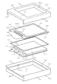
次に、添付図面を参照して本発明の実施形態について詳細に説明する。図1は、本実施
形態に係る電気光学装置(液晶表示装置)100の概略分解斜視図である。この電気光学
装置100は、バックライトを構成する照明ユニット110と、該照明ユニット110の
前面側(観察側)に配置される電気光学パネル(液晶表示パネル)120とを具備すると
ともに、これらを収容保持する収容部材としての支持フレーム130と、支持部材として
の内側フレーム140と、装着部材としての保持フレーム150とを有する保持体を具備
している。
[First Embodiment]
Next, embodiments of the present invention will be described in detail with reference to the accompanying drawings. FIG. 1 is a schematic exploded perspective view of an electro-optical device (liquid crystal display device) 100 according to this embodiment. The electro-
照明ユニット110は、LED(発光ダイオード)、冷陰極管等で構成される光源11
1と、光源111から放出される光を光入射面(端面)112aから導入して光出射面(
表面)112bから出射する導光板112とを備えている。ここで、配線基板(フレキシ
ブル配線基板)113上に複数の光源111が実装され、上記光入射面112aの幅方向
(側壁133と平行な方向)に沿って配列されている。また、導光板112の背後には反
射シート114が配置される。さらに、図示しない光学シートが上記光出射面112b上
に配置されることが好ましい。ここで、導光板112は平面視矩形状に構成される。
The
1 and the light emitted from the
A
電気光学パネル120は、ガラス等よりなる透明な基板121と122とが貼り合わさ
れ、この間に図示しない電気光学物質(液晶)が配置されたものである。基板121には
基板122より張り出した基板張り出し部121Tが設けられ、この基板張り出し部12
1T上には駆動回路123や信号入力用の配線基板(フレキシブル配線基板)124が実
装されている。なお、必要に応じて基板121,122の外面上に偏光板126(基板1
21側の偏光板は図示省略)が配置(貼着)される。電気光学パネル120は平面視矩形
状に構成され、その表示領域120Aも矩形状に構成されている。
The electro-
A
The 21 side polarizing plate is arranged (attached). The electro-
支持フレーム130は、平面視矩形状に構成され、底面131と、この底面131の側
方に立設された4つの側壁132,133とを有する。側壁132は一辺が開いた矩形状
に3つ設けられ、残りの一つの側壁133の上縁が他の側壁132の上縁よりやや低く形
成され、後述するように保持フレーム150を装着した場合でも上記配線基板113,1
24の導出口が確保されるように構成されている。支持フレーム130の内部には内側フ
レーム140が収容され、この内側フレーム140の内側には、照明ユニット110が収
容配置される。また、電気光学パネル120は、必要に応じて両面接着テープ127等を
介して、内側フレーム140の周囲に設けられたパネル支持面140a上に支持される。
The
Twenty-four outlets are secured. An
保持フレーム150は図示例の場合、電気光学パネル120を上方より覆うように装着
される。保持フレーム150は下部が開口し、上記支持フレーム130に装着可能に構成
され、上部に電気光学パネル120の表示領域120Aを観察側(図示上方)より視認可
能に構成するための表示窓150aを備えている。保持フレーム150は、表示窓150
aを開口してなる上面部151と、この上面部151の周囲より下方に向けて立設される
側壁152,153とを備えている。保持フレーム150は平面視矩形状で、上記支持フ
レーム130に対応する平面形状、すなわち、図示例の場合には支持フレーム130より
僅かに小さく、支持フレーム130の側壁132,133の内側にその側壁152,15
3が挿入される寸法に構成される。3つの側壁152は支持フレーム130の側壁132
と対応して一辺が開いた矩形状に構成され、残りの1つの側壁153の下縁は他の側壁1
52の下縁より低く形成され、組立状態において上記支持フレーム130の側壁133の
上縁との間に上述の導出口を確保するように構成される。
In the illustrated example, the
An
3 is configured to be inserted. The three
And the lower edge of the remaining
The lower outlet 52 is formed lower than the lower edge of the
(構成例1)図2は上記実施形態の具体的な構成例1を示す概略部分断面図である。本
構成例の場合、一例として、支持フレーム130と内側フレーム140とを係合固定する
ための係合構造が設けられる。この係合構造は、たとえば、図2に示すように、支持フレ
ーム130の側壁132の内面と、内側フレーム140の外周面との間に形成される。支
持フレーム130の側壁132は、底面131より立設された基部132aと、この基部
132aの上端に設けられた屈折部132bにて内側に折り返され、上記基部132aの
内面上に重ねて配置される折り返し範囲132cとを有している。この折り返し範囲13
2cの先端は基部132aの高さ方向途中に配置され、この先端の端面が基部132aの
内側で段部132dを構成している。
(Configuration Example 1) FIG. 2 is a schematic partial sectional view showing a specific configuration example 1 of the above embodiment. In the case of this configuration example, as an example, an engagement structure for engaging and fixing the
The tip of 2c is arranged in the middle of the
内側フレーム140の外周面には突出部141が形成され、この突出部141の上面が
段部141aを構成している。内側フレーム140を支持フレーム130の内部に挿入す
ると、内側フレーム140の上記突出部141は側壁132の内面上の折り返し範囲13
2cに当接し、側壁132をやや外側に変形させながら支持フレーム130内に導入され
、この支持フレーム130の内部に形成された上記段部132dの下方に段部141aが
収まることで、内側フレーム140は、段部132dと底面131とに挟持され、支持フ
レーム130に保持される。そして、保持フレーム150の側壁152,153が電気光
学パネル120と内側フレーム140に挟持されることで固定されている。
A projecting
2c is introduced into the
この図2に示す例では、支持フレーム130を金属板で構成することができ、また、内
側フレーム140を白色ポリエチレン等の合成樹脂で構成することができる。この場合、
主として支持フレーム130の弾性変形によって図示の係合状態を得ることができるよう
になっている。ただし、内側フレーム140を構成する素材は合成樹脂に限られることな
く、たとえば、支持フレーム130と同様の金属板で構成されていてもよい。
In the example shown in FIG. 2, the
The illustrated engagement state can be obtained mainly by elastic deformation of the
この例では、支持フレーム130の側壁132が上部に屈折部132bを有し、折り返
し範囲132cが基部132aに重ねられた状態とされるので、側壁132自体の剛性を
高めることができるとともに、段部132dの剛性は金属板の厚みとは無関係に折り返し
範囲132cの屈折部132bから先端までの長さに応じて増大するため、係合強度も大
幅に高めることができる。さらに、折り返し範囲132cの先端で段部132dが形成さ
れるため、側壁132に係合用開口部、或いは、切り込みを入れた上で折り曲げ形成され
る係合片などを設けることが不要となり、側壁132の剛性を低下させる虞もなくなる。
In this example, the
(構成例2)図3は構成例2に係る一例を示す概略部分断面図である。この構成例では
、図3に示すように、支持フレーム130と保持フレーム150とが直接係合している。
支持フレーム130は図2に示す場合と同様に金属板で構成されるとともに、側壁132
を内側に折り返すことで屈折部132bが形成され、この屈折部132bを経て折り返し
範囲132cが基部132aの内面上に重ねられ、当該折り返し範囲132cの先端が段
部132dを構成している。一方、保持フレーム150は特に限定されないが、図示例の
場合、支持フレーム130と同様に金属板で構成されている。保持フレーム150の側壁
152の下縁には外側に折り曲げられた係合突起152aが形成され、この係合突起15
2aの先端が上記段部132dと係合し、保持されている。なお、この係合突起152a
を、上記段部132dと同様に、金属板を外側へ折り返して基部を経て基部の外面上に配
置される折り返し範囲の先端で構成される段部とすることも可能である。
(Configuration Example 2) FIG. 3 is a schematic partial sectional view showing an example according to Configuration Example 2. In this configuration example, as shown in FIG. 3, the
The
Is folded inward to form a refracting
The tip of 2a is engaged with and held by the
Similarly to the
本構成例では、保持フレーム150が支持フレーム130に対して係合保持されている
だけでなく、保持フレーム150の上記係合突起152aの折曲部152bが内側フレー
ム140の外周に設けられた突出部141の段部141aと当接し、これによって内側フ
レーム140が支持フレーム130及び保持フレーム150に対して係合保持された状態
とされている。
In this configuration example, not only the holding
本構成例では、上記支持フレーム130の全体が金属板で構成されていることを前提と
して説明したが、支持フレーム130の一部が金属板で構成されたもの、たとえば、金属
板と合成樹脂とが一体化されたものなどであってもよい。また、本構成例では、支持フレ
ーム130に折り返し範囲132cが形成されて段部132dが構成されているが、同様
の構造を内側フレーム140又は保持フレーム150に適用してもよい。内側フレーム1
40に適用した場合には、図3に代えて図10に示す構造を適用することで対応可能とな
る。この場合、突出部141に代えて段部141aで係合されることとなる。さらに、上
記係合構造では折り返し範囲132cを側壁132の内側に折り返すことで形成している
が、外側に折り返し範囲132cを折り返し、側壁132の外面上に段部を設けるように
してもよい。外側に折り返した場合には、保持フレーム150は支持フレーム130の外
側で係合されるため、保持フレーム150は支持フレーム130よりも平面視にて大きい
形状を有し、折り返し方向が内側向きになるよう構成されることとなる。
In this configuration example, the description has been made on the assumption that the
When applied to 40, the structure shown in FIG. 10 can be applied instead of FIG. In this case, it will be engaged by the
また、本構成例では支持フレーム130に段部132dを形成し、段部132dで他の
部材を保持しているが、段部132dは、種々の部材を保持するための保持構造として用
いることができる。たとえば、電気光学パネル120の周縁部を支持フレーム130の内
部に保持する用途に用いても構わない。
In this configuration example, the
また、本構成例では、折り返し範囲132cを支持フレーム130の側壁132の延長
方向(底面131の周囲を周回する方向)に沿って伸びる形状としている。これによって
、側壁132の剛性をより高めることができるとともに保持力も増強できる。ここで、係
合段差の形成に関して、折り返し範囲132cを側壁132の延長方向の一部にのみ形成
したり、当該延長方向の異なる位置に、異なる高さに形成してもよい。たとえば、図4に
示すように、折り返し範囲132cによる段部132dが高い位置にあるのに対して、別
の場所の段部132d'はこれよりも低い位置にある。また、折り返し範囲132cの先
端が底面131にほぼ当接して段部が形成されていない場所132d''も設けられている
。このように段部132d,132d'の位置が局所に限定されていたり、場所によって
異なる位置に設けられていたりした場合でも、側壁132の上部に屈折部132bが設け
られている点、基部に重なる折り返し範囲132cが存在する点は上記と同様であり、側
壁132の剛性を高めることができるとともに係合構造の強度も向上できる。
Further, in the present configuration example, the
(構成例3)図8(a),(b)は別の構成例3を示す概略部分断面図である。この構
成例では、図8(a)に示すように、支持フレーム130と保持フレーム150とが直接
係合している。そして保持フレーム150の折曲部152bは支持フレーム130の底面
131と直接接触している。
支持フレーム130は図2に示す場合と同様に金属板で構成されるとともに、側壁13
2を内側に折り返すことで屈折部132bが形成され、この屈折部132bを経て折り返
し範囲132cが基部132aの内面上に重ねられ、当該折り返し範囲(装着領域)13
2cの先端が段部132dを構成している。一方、保持フレーム150は特に限定されな
いが、図示例の場合、支持フレーム130と同様に金属板で構成されている。保持フレー
ム150の側壁152の下縁には外側に折り曲げられた係合突起152aが形成され、こ
の係合突起152aの先端が上記段部132dと係合し、保持されている。そして、折曲
部152bと支持フレーム130の底面131と直接接触することで保持フレーム150
は支持フレーム130上に保持される。
また、図8(b)に示すように、屈折部132bを介して段部132dを形成する構成
に代えて、保持フレーム150の側壁152に金属や樹脂を貼り付けて段差を形成、保持
フレーム150の側壁152と同一材料となる金属や樹脂で段差を形成、保持フレーム1
50の側壁152に金属や樹脂を一体的に成形し段差を形成する段差領域154を形成し
てもよい。屈折部132bを形成するために必要な大きな応力をかける工程を省略できる
ため、保持フレーム150の変形を抑えることが可能となる。
また、本構成例では、保持フレーム150と支持フレーム130とが直接係合固定され
るため、寸法誤差の発生源が少なく、より精密に位置決めをすることが可能となる。
本構成例では上記支持フレーム130の全体が金属板で構成されていることを前提とし
て説明したが、支持フレーム130の一部が金属板で構成されたもの、たとえば、金属板
と合成樹脂とが一体化されたものなどであってもよい。
(Configuration Example 3) FIGS. 8A and 8B are schematic partial sectional views showing another configuration example 3. FIG. In this configuration example, as shown in FIG. 8A, the
The
2 folds inward to form a refracting
The tip of 2c constitutes a
Is held on the
Further, as shown in FIG. 8B, a step is formed by attaching metal or resin to the
A
Further, in this configuration example, the holding
In this configuration example, the description has been made on the assumption that the
(変形例)第1実施形態で記載した図2、図3における内側フレーム140はインサー
ト成形法を用いて作成することが好適である。インサート成形法を用いて内側フレーム1
40を形成することで、支持フレーム130を内側フレーム140に係合させる場合と比
べ、内側フレーム140との密着性を向上させることが可能となる。そのため、内側フレ
ーム140は支持フレーム130の補強材としても機能し、薄型化が要求される電気光学
装置100の強度を向上させることが可能となる。また、図9(a)に示すように、内側
フレーム140をインサート成形法で形成し、さらに側壁132,133の外側に外側樹
脂部160を形成してもよい。図9(a)は図2に示す構造に対して外側樹脂部160を
形成したものである。この場合と同様に、図3に示す構造に対しても同様に外側樹脂部1
60を設けることができる。外側樹脂部160を設けることで、支持フレーム130を補
強することが可能となる。なお、外側樹脂部160を設ける場合に内側フレーム140を
有することは必須ではなく、たとえば、図9(b)のように図8(a)に示す構造に外側
樹脂部160をインサート成形法で配置してもよく、この場合においても電気光学パネル
120に印加される応力を外側樹脂部160で分散することが可能とする効果を得ること
ができる。
(Modification) The
By forming 40, it is possible to improve the adhesion with the
60 can be provided. By providing the
[第2実施形態]
次に、図5を参照して本発明に係る第2実施形態について説明する。この実施形態の電
気光学装置では、上記図1に示す全体構成と同様の構成を有するため、同一の部分には同
一符号を付し、それらの説明は省略する。
[Second Embodiment]
Next, a second embodiment according to the present invention will be described with reference to FIG. Since the electro-optical device of this embodiment has the same configuration as the overall configuration shown in FIG. 1, the same reference numerals are given to the same parts, and descriptions thereof are omitted.
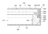
図5に示すように、本実施形態では、側壁132の基部132aから屈折部132bを
介して折り返し範囲132cが折り返して設けられ、折り返し範囲132cの先端が段部
132dを構成している点では第1実施形態と同様であり、当該段部132dの用い方も
第1実施形態の説明通りである。
As shown in FIG. 5, in the present embodiment, the
本実施形態では、折り返し範囲132cの先端である段部132dに臨むように基部1
32aに開口部132eが形成されている。すなわち、開口部132eは折り返し範囲1
32cの先端が平面的に開口範囲内に配置されるように構成される。図示例では、折り返
し範囲132cの先端は開口部132eの上側の開口縁と平面的に一致する位置に形成さ
れている。
In the present embodiment, the base portion 1 faces the
An
The tip of 32c is configured to be disposed within the opening range in a planar manner. In the illustrated example, the tip of the
本実施形態では、基部132aに開口部132eを設けることで、段部132dの係合
深さを折り返し範囲132cの厚みにとどまらず、十分に確保することができる。そのた
め、係合状態の安定化や係合構造の設計自由度の増大を図ることができる。図5では、保
持フレーム150の側壁152に設けられた係合突起152aが、折り返し範囲132c
の先端と開口部132eの開口縁とが積層されてなる段部132dに係合し、図3に示す
構成例の場合よりも係合突起152aの係合深さが大きく確保されている。したがって、
係合突起152aの係合状態がより安定するために確実に保持できるとともに、係合突起
152aの形状・寸法の自由度も増大する。
In the present embodiment, by providing the
Is engaged with a stepped
Since the engagement state of the
[電子機器]
最後に、図6及び図7を参照して上述した各実施形態に係る電気光学装置を電子機器に
搭載してなる実施形態に説明する。この電子機器200は、上記電気光学装置100を表
示部に搭載してなる電子機器であり、図6は、本発明に係る電子機器の一実施形態である
携帯電話機を示している。ここに示す電子機器200は、複数の操作ボタン、送話口など
を備えた操作部201と、受話口などを備えた表示部202とを有し、表示部202の内
部に上記の電気光学装置100が組み込まれてなる。そして表示部202の表面(内面)
上に電気光学装置100の表示領域120A(図1参照)を視認することができるように
なっている。この場合、電子機器200の内部には、上記電気光学装置100を制御する
後述の表示制御回路が設けられ、この表示制御回路が電気光学装置100の表示態様を決
定する。
[Electronics]
Finally, an embodiment in which the electro-optical device according to each embodiment described above with reference to FIGS. 6 and 7 is mounted on an electronic apparatus will be described. The
The
なお、電子機器200において、上記保持体の少なくとも一部を電子機器200側に固
定されたフレーム、電子機器200の筐体自体で構成することもできる。このようにする
と、表示部202の開口形状に対して高精度に整合した位置に表示画面を設定することが
できる。
Note that in the
図7は、電子機器における電気光学装置100に対する制御系(表示制御系)の全体構
成を示す概略構成図である。ここに示す電子機器は、表示情報出力源291と、表示情報
処理回路292と、電源回路293と、タイミングジェネレータ294と、照明ユニット
110への電力供給を行う光源制御回路295とを含む表示制御回路290を有する。ま
た、電気光学装置(液晶表示装置)100には、上述の構成を有する電気光学パネル12
0と、この電気光学パネル120を駆動する駆動回路123と、電気光学パネル120を
照明するためのバックライトである上記照明ユニット(照明装置)110とが設けられて
いる。この駆動回路123は、上記のように電気光学パネル120に直接実装されている
電子部品で構成されるが、上記のような態様の他に、電気光学パネル120の基板表面上
に形成された回路パターン、或いは、電気光学パネル120に導電接続された回路基板、
上記の配線基板124などの他の電子部品上に実装された半導体ICチップ若しくは回路
パターンなどによっても構成することができる。
FIG. 7 is a schematic configuration diagram illustrating an overall configuration of a control system (display control system) for the electro-
0, a driving
It can also be configured by a semiconductor IC chip or a circuit pattern mounted on another electronic component such as the
表示情報出力源291は、ROM(Read Only Memory)やRAM(Random Access Memo
ry)等からなるメモリと、磁気記録ディスクや光記録ディスク等からなるストレージユニ
ットと、デジタル画像信号を同調出力する同調回路とを備え、タイミングジェネレータ2
94によって生成された各種のクロック信号に基づいて、所定フォーマットの画像信号等
の形で表示情報を表示情報処理回路292に供給するように構成されている。
The display
ry) and the like, a storage unit composed of a magnetic recording disk, an optical recording disk, and the like, and a tuning circuit that tunes and outputs a digital image signal.
The display information is supplied to the display
表示情報処理回路292は、シリアル−パラレル変換回路、増幅・反転回路、ローテー
ション回路、ガンマ補正回路、クランプ回路等の周知の各種回路を備え、入力した表示情
報の処理を実行して、その画像情報をクロック信号CLKと共に駆動回路123へ供給す
る。駆動回路123は、走査線駆動回路、信号線駆動回路及び検査回路を含む。また、電
源回路293は、上述の各構成要素にそれぞれ所定の電圧を供給する。
The display
光源制御回路295は、電源回路293から供給される電圧に基づいて照明ユニット1
10の光源に電力を供給し、所定の制御信号に基づいて光源の点灯の有無及びその輝度等
を制御するようになっている。
The light
Electric power is supplied to 10 light sources, and the presence / absence of the light source and its brightness are controlled based on a predetermined control signal.
また、本発明に係る電子機器としては、図6に示す携帯電話機の他に、液晶テレビ、カ
ーナビゲーション装置、ページャ、電子手帳、電卓、ワークステーション、テレビ電話、
POS端末機などが挙げられる。そして、これらの各種電子機器の表示部として本発明に
係る電気光学装置(液晶表示装置)を用いることができる。
In addition to the mobile phone shown in FIG. 6, the electronic apparatus according to the present invention includes a liquid crystal television, a car navigation device, a pager, an electronic notebook, a calculator, a workstation, a video phone,
A POS terminal is exemplified. The electro-optical device (liquid crystal display device) according to the present invention can be used as a display unit of these various electronic devices.
なお、本発明は、上述の図示例にのみ限定されるものではなく、本発明の要旨を逸脱し
ない範囲内において種々変更を加え得ることは勿論である。例えば、上記の実施形態にお
いては、電気光学パネルの例示として液晶表示パネルを備えた液晶表示装置について説明
したが、本発明は、液晶表示装置に限らず、有機エレクトロルミネッセンス表示装置や電
気泳動表示装置などの他の電気光学装置であっても構わない。
It should be noted that the present invention is not limited to the illustrated examples described above, and it is needless to say that various modifications can be made without departing from the scope of the present invention. For example, in the above embodiment, the liquid crystal display device including the liquid crystal display panel has been described as an example of the electro-optical panel. However, the present invention is not limited to the liquid crystal display device, and is an organic electroluminescence display device or an electrophoretic display device. Other electro-optical devices may be used.
100…電気光学装置、110…照明ユニット、111…光源、112…導光板、11
2a…光入射面、112b…光出射面、113…配線基板、114…反射シート、120
…電気光学パネル、120A…表示領域、121…基板、122…基板、121T…基板
張り出し部、122…基板、123…駆動回路、124…配線基板、125…偏光板、1
27…両面接着テープ、130…収容部材としての支持フレーム、131…底面、132
…側壁、132a…基部、132b…屈折部、132c…折り返し範囲、132d…段部
、132d'…段部、132d''…段部が形成されていない場所、132e…開口部、1
33…側壁、140…支持部材としての内側フレーム、140a…パネル支持面、141
…突出部、141a…段部、150…装着部材としての保持フレーム、150a…表示窓
、151…上面部、152…側壁、152a…係合突起、152b…折曲部、153…側
壁、154…段差領域、160…外側樹脂部、200…電子機器、201…操作部、20
2…表示部、290…表示制御回路、291…表示情報出力源、292…表示情報処理回
路、293…電源回路、294…タイミングジェネレータ、295…光源制御回路。
DESCRIPTION OF
2a ... light incident surface, 112b ... light emitting surface, 113 ... wiring substrate, 114 ... reflective sheet, 120
DESCRIPTION OF SYMBOLS ... Electro-optical panel, 120A ... Display area, 121 ... Substrate, 122 ... Substrate, 121T ... Substrate overhanging part, 122 ... Substrate, 123 ... Drive circuit, 124 ... Wiring substrate, 125 ... Polarizing plate, 1
27: Double-sided adhesive tape, 130: Support frame as housing member, 131: Bottom surface, 132
... side wall, 132a ... base, 132b ... refracting part, 132c ... folding range, 132d ... step, 132d '... step, 132d''... place where no step is formed, 132e ... opening, 1
33 ... side wall, 140 ... inner frame as a support member, 140a ... panel support surface, 141
... Projection part, 141a ... Step part, 150 ... Holding frame as mounting member, 150a ... Display window, 151 ... Upper surface part, 152 ... Side wall, 152a ... Engagement projection, 152b ... Bending part, 153 ... Side wall, 154 ... Step region, 160 ... outer resin part, 200 ... electronic device, 201 ... operation part, 20
DESCRIPTION OF SYMBOLS 2 ... Display part, 290 ... Display control circuit, 291 ... Display information output source, 292 ... Display information processing circuit, 293 ... Power supply circuit, 294 ... Timing generator, 295 ... Light source control circuit.
Claims (6)
前記支持フレームは、前記電気光学パネルの前記一方の面側に配置される第1の底面と、当該第1の底面から立設される第1の側壁と、を有し、前記保持フレームは、前記電気光学パネルの前記他方の面側に配置される第2の底面と、当該第2の底面から立設され前記支持フレームの前記第1の側壁の内側に配置される第2の側壁と、を有し、前記支持フレームは、前記第1の側壁の少なくとも一部が当該支持フレームの内側に折り返された先端によって第1の段部を形成し、前記内側フレームは、前記支持フレームの前記第1の側壁に対向する面に前記保持フレーム側に向いた第2の段部を有し、前記保持フレームと前記支持フレームとで前記電気光学パネル及び前記内側フレームを収容した状態において、前記支持フレームの前記第1の段部が内側フレームの前記第2の段部に当接し、前記保持フレームの前記第2の側壁が前記内側フレームと前記支持フレームの前記第1の側壁との間に狭持されることを特徴とする電気光学装置。 The electro-optical panel, a support frame disposed on one surface side of the electro-optical panel, a holding frame disposed on the other surface side of the electro-optical panel, and the support frame and the holding frame are accommodated. An inner frame that supports the electro-optic panel from the support frame side,
The support frame includes a first bottom surface disposed on the one surface side of the electro-optic panel, and a first side wall erected from the first bottom surface, and the holding frame is A second bottom surface disposed on the other surface side of the electro-optical panel; a second side wall disposed upright from the second bottom surface and disposed inside the first side wall of the support frame; The support frame forms a first step portion by a tip end of which at least a part of the first side wall is folded back inside the support frame, and the inner frame includes the first step of the support frame. The support frame has a second step portion facing the holding frame on a surface facing the side wall of the first frame, and the electro-optical panel and the inner frame are accommodated by the holding frame and the support frame. The first of And the second side wall of the holding frame is sandwiched between the inner frame and the first side wall of the support frame. An electro-optical device.
前記支持フレームは、前記電気光学パネルの前記一方の面側に配置される第1の底面と、当該第1の底面から立設される第1の側壁と、を有し、前記保持フレームは、前記電気光学パネルの前記他方の面側に配置される第2の底面と、当該第2の底面から立設され前記支持フレームの前記第1の側壁の内側に配置される第2の側壁と、を有し、前記支持フレームは、前記第1の側壁の少なくとも一部が当該支持フレームの内側に折り返された先端によって第1の段部を形成し、前記保持フレームの前記第2の側壁の縁には外側に折り曲げられた係合突起が形成され、前記保持フレームと前記支持フレームとで前記電気光学パネルを収容した状態において、前記第1の段部と前記係合突起とが係合していることを特徴とする電気光学装置。 The electro-optical panel, a support frame disposed on one surface side of the electro-optical panel, a holding frame disposed on the other surface side of the electro-optical panel, and the support frame and the holding frame are accommodated. An inner frame that supports the electro-optic panel from the support frame side ,
The support frame includes a first bottom surface disposed on the one surface side of the electro-optic panel, and a first side wall erected from the first bottom surface, and the holding frame is A second bottom surface disposed on the other surface side of the electro-optical panel; a second side wall disposed upright from the second bottom surface and disposed inside the first side wall of the support frame; The support frame forms a first step portion by a tip end of which at least a part of the first side wall is folded back inside the support frame, and an edge of the second side wall of the holding frame Is formed with an engagement projection bent outward, and the first stepped portion and the engagement projection are engaged with each other when the electro-optical panel is accommodated by the holding frame and the support frame. An electro-optical device.
Priority Applications (5)
| Application Number | Priority Date | Filing Date | Title |
|---|---|---|---|
| JP2008120212A JP4508265B2 (en) | 2007-06-27 | 2008-05-02 | Electro-optical device and electronic apparatus |
| TW97123932A TW200919013A (en) | 2007-06-27 | 2008-06-26 | Electrooptical device and electronic apparatus |
| KR1020080060880A KR100990607B1 (en) | 2007-06-27 | 2008-06-26 | Electronic optical device and electronic apparatus |
| US12/146,551 US7859831B2 (en) | 2007-06-27 | 2008-06-26 | Electro-optical device and electronic apparatus |
| CN2008101292529A CN101334538B (en) | 2007-06-27 | 2008-06-26 | Electro-optical device and electronic apparatus |
Applications Claiming Priority (2)
| Application Number | Priority Date | Filing Date | Title |
|---|---|---|---|
| JP2007168594 | 2007-06-27 | ||
| JP2008120212A JP4508265B2 (en) | 2007-06-27 | 2008-05-02 | Electro-optical device and electronic apparatus |
Publications (2)
| Publication Number | Publication Date |
|---|---|
| JP2009031753A JP2009031753A (en) | 2009-02-12 |
| JP4508265B2 true JP4508265B2 (en) | 2010-07-21 |
Family
ID=40197236
Family Applications (1)
| Application Number | Title | Priority Date | Filing Date |
|---|---|---|---|
| JP2008120212A Active JP4508265B2 (en) | 2007-06-27 | 2008-05-02 | Electro-optical device and electronic apparatus |
Country Status (3)
| Country | Link |
|---|---|
| JP (1) | JP4508265B2 (en) |
| CN (1) | CN101334538B (en) |
| TW (1) | TW200919013A (en) |
Families Citing this family (14)
| Publication number | Priority date | Publication date | Assignee | Title |
|---|---|---|---|---|
| JP2010256702A (en) * | 2009-04-27 | 2010-11-11 | Casio Computer Co Ltd | Display device |
| CN104133314B (en) | 2009-05-02 | 2019-07-12 | 株式会社半导体能源研究所 | Show equipment |
| JP2011180237A (en) * | 2010-02-26 | 2011-09-15 | Hitachi Consumer Electronics Co Ltd | Video display device |
| CN102404952A (en) * | 2010-09-16 | 2012-04-04 | 富泰华工业(深圳)有限公司 | Electronic device and forming method for metal shell of same |
| JP2012124224A (en) * | 2010-12-06 | 2012-06-28 | Mitsubishi Plastics Inc | Frame like member and housing |
| JP2012124225A (en) * | 2010-12-06 | 2012-06-28 | Mitsubishi Plastics Inc | Back chassis and housing |
| CN102869211A (en) * | 2011-07-08 | 2013-01-09 | 深圳富泰宏精密工业有限公司 | Casing and manufacturing method thereof |
| CN102506394A (en) | 2011-10-28 | 2012-06-20 | 深圳市华星光电技术有限公司 | Front frame and backlight module |
| CN103091899B (en) * | 2011-11-03 | 2015-09-30 | 苏州璨宇光学有限公司 | Display device and backlight module thereof |
| TWI463212B (en) | 2011-11-17 | 2014-12-01 | Au Optronics Corp | Display apparatus |
| KR102068955B1 (en) * | 2012-08-16 | 2020-01-22 | 엘지디스플레이 주식회사 | Backlight unit |
| CN105659162B (en) * | 2013-09-11 | 2017-10-24 | 贺利氏特种光源美国有限责任公司 | Large area high uniformity ultraviolet source with many small transmitters |
| JP6584143B2 (en) * | 2015-05-27 | 2019-10-02 | 三菱電機株式会社 | Backlight and display device |
| CN105618594B (en) * | 2015-11-25 | 2018-01-09 | 东莞酷派软件技术有限公司 | The installation method of screen, the assemble method of terminal and terminal |
Citations (4)
| Publication number | Priority date | Publication date | Assignee | Title |
|---|---|---|---|---|
| JPH0682782A (en) * | 1992-08-31 | 1994-03-25 | Hitachi Ltd | Liquid crystal display device |
| JPH095744A (en) * | 1995-04-20 | 1997-01-10 | Toshiba Corp | Plane display device |
| JP2002215051A (en) * | 2000-12-04 | 2002-07-31 | Chi Mei Optoelectronics Corp | Reinforced bezel with structure for flat-panel display |
| JP2006011163A (en) * | 2004-06-28 | 2006-01-12 | Toshiba Corp | Protective structure for liquid crystal display of electronic apparatus |
-
2008
- 2008-05-02 JP JP2008120212A patent/JP4508265B2/en active Active
- 2008-06-26 TW TW97123932A patent/TW200919013A/en unknown
- 2008-06-26 CN CN2008101292529A patent/CN101334538B/en active Active
Patent Citations (4)
| Publication number | Priority date | Publication date | Assignee | Title |
|---|---|---|---|---|
| JPH0682782A (en) * | 1992-08-31 | 1994-03-25 | Hitachi Ltd | Liquid crystal display device |
| JPH095744A (en) * | 1995-04-20 | 1997-01-10 | Toshiba Corp | Plane display device |
| JP2002215051A (en) * | 2000-12-04 | 2002-07-31 | Chi Mei Optoelectronics Corp | Reinforced bezel with structure for flat-panel display |
| JP2006011163A (en) * | 2004-06-28 | 2006-01-12 | Toshiba Corp | Protective structure for liquid crystal display of electronic apparatus |
Also Published As
| Publication number | Publication date |
|---|---|
| CN101334538A (en) | 2008-12-31 |
| CN101334538B (en) | 2010-08-18 |
| JP2009031753A (en) | 2009-02-12 |
| TW200919013A (en) | 2009-05-01 |
| TWI374309B (en) | 2012-10-11 |
Similar Documents
| Publication | Publication Date | Title |
|---|---|---|
| JP4508265B2 (en) | Electro-optical device and electronic apparatus | |
| KR100990607B1 (en) | Electronic optical device and electronic apparatus | |
| JP4471022B2 (en) | Electro-optical device substrate and electronic apparatus | |
| KR100984909B1 (en) | Electro optical device and electronic device | |
| JP4007340B2 (en) | Electro-optical device, electronic apparatus, and method of manufacturing electro-optical device | |
| JP4616105B2 (en) | Liquid crystal display device | |
| JP4353266B2 (en) | Electro-optical device and electronic apparatus | |
| KR100681604B1 (en) | Electro-optical device and electronic apparatus | |
| JP5582677B2 (en) | Liquid crystal display | |
| KR100419043B1 (en) | Liqid crystal module supporting structure and mobile terminal mounted with the same | |
| JP4534972B2 (en) | Electro-optical device and electronic apparatus | |
| JP2010060866A (en) | Electro-optical panel, electro-optical device, and electronic equipment | |
| JP4900054B2 (en) | LIGHTING DEVICE, ELECTRO-OPTICAL DEVICE, AND ELECTRONIC DEVICE | |
| JP5506012B2 (en) | LCD module | |
| JP5076669B2 (en) | Electro-optical device, holding frame, and electronic apparatus | |
| JP3838067B2 (en) | Light guide plate, light guide plate fixing structure, liquid crystal display device and electronic apparatus | |
| JP4297021B2 (en) | ELECTRO-OPTICAL DEVICE, LIGHTING DEVICE, AND ELECTRONIC DEVICE | |
| JP2009192769A (en) | Liquid crystal display device | |
| JP2009186971A (en) | Electro-optical device and electronic equipment | |
| JP2009294346A (en) | Electrooptical apparatus and electronic device | |
| KR20140118413A (en) | Liquid Crystal Display Device | |
| KR20080070279A (en) | Back light assembly and display apparatus having the same | |
| JP2008275815A (en) | Electro-optical device and electronic apparatus | |
| JP4655561B2 (en) | Electro-optical device and electronic apparatus | |
| JP4432424B2 (en) | Liquid crystal display device and electronic device |
Legal Events
| Date | Code | Title | Description |
|---|---|---|---|
| A977 | Report on retrieval |
Free format text: JAPANESE INTERMEDIATE CODE: A971007 Effective date: 20090529 |
|
| A131 | Notification of reasons for refusal |
Free format text: JAPANESE INTERMEDIATE CODE: A131 Effective date: 20090609 |
|
| A521 | Request for written amendment filed |
Free format text: JAPANESE INTERMEDIATE CODE: A523 Effective date: 20090727 |
|
| A131 | Notification of reasons for refusal |
Free format text: JAPANESE INTERMEDIATE CODE: A131 Effective date: 20091027 |
|
| A521 | Request for written amendment filed |
Free format text: JAPANESE INTERMEDIATE CODE: A523 Effective date: 20091224 |
|
| TRDD | Decision of grant or rejection written | ||
| A01 | Written decision to grant a patent or to grant a registration (utility model) |
Free format text: JAPANESE INTERMEDIATE CODE: A01 Effective date: 20100413 |
|
| A01 | Written decision to grant a patent or to grant a registration (utility model) |
Free format text: JAPANESE INTERMEDIATE CODE: A01 |
|
| A61 | First payment of annual fees (during grant procedure) |
Free format text: JAPANESE INTERMEDIATE CODE: A61 Effective date: 20100426 |
|
| FPAY | Renewal fee payment (event date is renewal date of database) |
Free format text: PAYMENT UNTIL: 20130514 Year of fee payment: 3 |
|
| R150 | Certificate of patent or registration of utility model |
Ref document number: 4508265 Country of ref document: JP Free format text: JAPANESE INTERMEDIATE CODE: R150 Free format text: JAPANESE INTERMEDIATE CODE: R150 |
|
| S111 | Request for change of ownership or part of ownership |
Free format text: JAPANESE INTERMEDIATE CODE: R313113 |
|
| FPAY | Renewal fee payment (event date is renewal date of database) |
Free format text: PAYMENT UNTIL: 20130514 Year of fee payment: 3 |
|
| R350 | Written notification of registration of transfer |
Free format text: JAPANESE INTERMEDIATE CODE: R350 |
|
| FPAY | Renewal fee payment (event date is renewal date of database) |
Free format text: PAYMENT UNTIL: 20130514 Year of fee payment: 3 |
|
| S111 | Request for change of ownership or part of ownership |
Free format text: JAPANESE INTERMEDIATE CODE: R313113 |
|
| FPAY | Renewal fee payment (event date is renewal date of database) |
Free format text: PAYMENT UNTIL: 20130514 Year of fee payment: 3 |
|
| R350 | Written notification of registration of transfer |
Free format text: JAPANESE INTERMEDIATE CODE: R350 |
|
| R250 | Receipt of annual fees |
Free format text: JAPANESE INTERMEDIATE CODE: R250 |
|
| R250 | Receipt of annual fees |
Free format text: JAPANESE INTERMEDIATE CODE: R250 |
|
| R250 | Receipt of annual fees |
Free format text: JAPANESE INTERMEDIATE CODE: R250 |
|
| R250 | Receipt of annual fees |
Free format text: JAPANESE INTERMEDIATE CODE: R250 |
|
| R250 | Receipt of annual fees |
Free format text: JAPANESE INTERMEDIATE CODE: R250 |
|
| R250 | Receipt of annual fees |
Free format text: JAPANESE INTERMEDIATE CODE: R250 |
|
| R250 | Receipt of annual fees |
Free format text: JAPANESE INTERMEDIATE CODE: R250 |
|
| R250 | Receipt of annual fees |
Free format text: JAPANESE INTERMEDIATE CODE: R250 |
|
| R250 | Receipt of annual fees |
Free format text: JAPANESE INTERMEDIATE CODE: R250 |
|
| S111 | Request for change of ownership or part of ownership |
Free format text: JAPANESE INTERMEDIATE CODE: R313111 |
|
| R350 | Written notification of registration of transfer |
Free format text: JAPANESE INTERMEDIATE CODE: R350 |
|
| R250 | Receipt of annual fees |
Free format text: JAPANESE INTERMEDIATE CODE: R250 |
|
| R250 | Receipt of annual fees |
Free format text: JAPANESE INTERMEDIATE CODE: R250 |
|
| R250 | Receipt of annual fees |
Free format text: JAPANESE INTERMEDIATE CODE: R250 |