JP4507933B2 - Multi-cylinder engine controller - Google Patents
Multi-cylinder engine controller Download PDFInfo
- Publication number
- JP4507933B2 JP4507933B2 JP2005083659A JP2005083659A JP4507933B2 JP 4507933 B2 JP4507933 B2 JP 4507933B2 JP 2005083659 A JP2005083659 A JP 2005083659A JP 2005083659 A JP2005083659 A JP 2005083659A JP 4507933 B2 JP4507933 B2 JP 4507933B2
- Authority
- JP
- Japan
- Prior art keywords
- intake
- engine
- volume
- valve
- speed
- Prior art date
- Legal status (The legal status is an assumption and is not a legal conclusion. Google has not performed a legal analysis and makes no representation as to the accuracy of the status listed.)
- Expired - Fee Related
Links
Images


Classifications
-
- Y—GENERAL TAGGING OF NEW TECHNOLOGICAL DEVELOPMENTS; GENERAL TAGGING OF CROSS-SECTIONAL TECHNOLOGIES SPANNING OVER SEVERAL SECTIONS OF THE IPC; TECHNICAL SUBJECTS COVERED BY FORMER USPC CROSS-REFERENCE ART COLLECTIONS [XRACs] AND DIGESTS
- Y02—TECHNOLOGIES OR APPLICATIONS FOR MITIGATION OR ADAPTATION AGAINST CLIMATE CHANGE
- Y02T—CLIMATE CHANGE MITIGATION TECHNOLOGIES RELATED TO TRANSPORTATION
- Y02T10/00—Road transport of goods or passengers
- Y02T10/10—Internal combustion engine [ICE] based vehicles
- Y02T10/12—Improving ICE efficiencies
Description
本発明は多気筒エンジンの制御装置に関し、特に、インパルス(気筒内に導入される高圧の圧力波)を生成するパルス発生装置を備えた多気筒エンジンの制御装置に関する。 The present invention relates to a control device for a multi-cylinder engine, and more particularly to a control device for a multi-cylinder engine provided with a pulse generator that generates an impulse (a high-pressure pressure wave introduced into a cylinder).
従来より、インテークマニホールドのサージタンクと、サージタンクから分岐して各気筒の吸気ポートに接続された分岐管が設けられた多気筒エンジンの制御装置において、体積効率を高める技術が種々開発されている。 Conventionally, various technologies for improving volumetric efficiency have been developed in a control device for a multi-cylinder engine provided with a surge tank of an intake manifold and a branch pipe branched from the surge tank and connected to an intake port of each cylinder. .
例えば、特許文献1には、吸気ポート毎に通路長の異なる複数の吸気通路を設け、これら吸気通路を切替弁によって択一的にサージタンクと連通する技術が開示されている。
For example,
他方、非特許文献1には、インパルスによる低運転領域のトルクアップを図る技術が開示されている。その構成では、インテークマニホールドの分岐管途中に、当該分岐管の経路方向にストロークする電磁弁を設け、吸気行程の途中までは、電磁弁を閉じて負圧を形成し、吸気行程の下死点近傍にて電磁弁を開放することによって、急激に気筒内に空気を供給する構成が開示されている。
On the other hand, Non-Patent
また、特許文献2、非特許文献2には、インパルスを生成する装置として、フラップ弁を用いてパルスを発生させる装置が開示されている。
エンジンの燃費を抑制しつつ出力性能を高めるためには、全ての運転領域にわたってポンピングロスを抑制しつつ充分な体積効率を確保する必要がある。 In order to improve the output performance while suppressing the fuel consumption of the engine, it is necessary to ensure sufficient volume efficiency while suppressing the pumping loss over the entire operation range.
しかるに、上述したパルス発生装置においては、体積効率が高まるので、出力は向上するものの、当該パルス発生装置の開弁時に大きな負圧が生じるため、ポンピングロスも高くなり、燃費は低下する。そのため、単にパルス発生装置を用いただけでは、全ての運転領域に対応して燃費と出力とのバランスを取ることができなかった。 However, in the pulse generator described above, volume efficiency is increased, so that the output is improved, but a large negative pressure is generated when the pulse generator is opened, so that the pumping loss is also increased and the fuel consumption is reduced. For this reason, simply using the pulse generator cannot balance the fuel consumption and the output corresponding to all the operation areas.
本発明は上述のような不具合に鑑みてなされたものであり、運転領域に応じて燃費と出力とをバランスさせることのできる多気筒エンジンの制御装置を提供することを課題としている。 The present invention has been made in view of the above-described problems, and an object thereof is to provide a control device for a multi-cylinder engine that can balance fuel consumption and output in accordance with an operation region.
前記課題を解決するために、本発明は、複数の気筒の各吸気ポートに空気を供給する吸気管と、各吸気管の上流端がそれぞれ開口する集合部と、各気筒の吸気行程に対応して、吸気ポートの開弁期間内の吸気行程途中で開弁して、気筒内に圧力波を生成するパルス発生装置とを備えた多気筒エンジンの制御装置において、エンジンの回転数を検出するエンジン回転数検出手段と、前記吸気管に連通する容積部と、容積部と吸気管との連通部分を開閉する容積部開閉機構と、前記エンジン回転数検出手段の検出に基づいてパルス発生装置の運転および容積部開閉機構の開閉動作を制御する制御手段とを設け、各吸気管の吸気ポート下流端から前記容積部までの吸気通路長は、第1の所定回転数以上の高速運転領域で動的過給できる長さに設定し、各吸気管の吸気ポート下流端から前記集合部までの吸気通路長は、前記第1の所定回転数よりも少ない第2の所定回転数以上の中速運転領域で動的過給できる長さに設定し、前記制御手段は、前記第1の所定回転数以上では、容積部を開くように容積部開閉機構を制御するとともに、前記第2の所定回転数に満たない運転領域では、パルス発生装置を作動させるものであることを特徴とする多気筒エンジンの制御装置である。 In order to solve the above-described problems, the present invention corresponds to an intake pipe that supplies air to each intake port of a plurality of cylinders, a collecting portion that opens at an upstream end of each intake pipe, and an intake stroke of each cylinder. An engine for detecting the rotational speed of an engine in a control device for a multi-cylinder engine having a pulse generator that opens during the intake stroke within a valve opening period of the intake port and generates a pressure wave in the cylinder The rotation number detecting means, the volume portion communicating with the intake pipe, the volume portion opening / closing mechanism for opening and closing the communicating portion between the volume portion and the intake pipe, and the operation of the pulse generator based on the detection of the engine speed detection means And a control means for controlling the opening / closing operation of the volume portion opening / closing mechanism, and the intake passage length from the intake port downstream end of each intake pipe to the volume portion is dynamic in a high-speed operation region of a first predetermined rotation speed or higher. Set to a length that allows supercharging. The length of the intake passage from the downstream end of the intake port of each intake pipe to the collecting portion is a length that allows dynamic supercharging in a medium speed operation region that is less than the first predetermined rotational speed and is equal to or higher than a second predetermined rotational speed. And the control means controls the volume part opening / closing mechanism so as to open the volume part at the first predetermined rotation speed or more, and in the operation region less than the second predetermined rotation speed, the pulse generator This is a control device for a multi-cylinder engine.
この態様では、エンジン回転数が第1の所定回転数以上の高速運転領域では、容積部が開くことにより、各吸気管の吸気ポート下流端から前記容積部までの間に動的過給を生じさせることが可能になる。このため、高速運転領域での体積効率が向上する。前記動的過給は、慣性過給であってもよいし、共鳴過給であってもよい。ここで、慣性過給とは、個々の気筒において吸気行程中に生じた圧力波がサージタンク等で反転して反射され、自気筒に対して吸気行程終期に作用することにより充填効率を高めるような動的効果をいう。また、共鳴過給とは、複数気筒において生じる吸気圧力振動が共鳴することによりに充填効率を高めるような動的効果をいう。尤も、動的過給として、慣性過給に対応して各吸気通路長を設定した場合には、共鳴過給に比べて距離を短くすることが可能になる。次に、この第1の所定回転数から第2の所定回転数までの中速運転領域では、容積部が閉じることにより、各吸気管の吸気ポート下流端から前記集合部までの間に動的過給を生じさせることが可能になる。このため、中速運転領域での体積効率が向上する。さらに、前記第2の所定回転数にも満たない低速運転領域では、容積部が閉じたままの状態でパルス発生装置が作動することにより、吸気管に圧力波を生成することができる。このため、低速運転領域での体積効率が向上する。 In this aspect, in a high-speed operation region where the engine speed is equal to or higher than the first predetermined speed, the volume portion is opened, thereby causing dynamic supercharging from the downstream end of the intake port of each intake pipe to the volume portion. It becomes possible to make it. For this reason, the volume efficiency in a high-speed driving | operation area | region improves. The dynamic supercharging may be inertia supercharging or resonance supercharging. Here, the inertia supercharging means that the pressure wave generated during the intake stroke in each cylinder is reversed and reflected by a surge tank or the like, and acts on the own cylinder at the end of the intake stroke to increase the charging efficiency. Dynamic effect. Resonance supercharging refers to a dynamic effect that enhances charging efficiency by resonating intake pressure oscillations occurring in a plurality of cylinders. However, when each intake passage length is set corresponding to inertial supercharging as dynamic supercharging, the distance can be shortened compared to resonance supercharging. Next, in the medium speed operation region from the first predetermined rotation speed to the second predetermined rotation speed, the volume portion is closed, so that the dynamic range between the downstream end of each intake port of each intake pipe and the collecting portion is obtained. It is possible to cause supercharging. For this reason, the volumetric efficiency in the medium speed operation region is improved. Further, in the low speed operation region that is less than the second predetermined rotation speed, a pressure wave can be generated in the intake pipe by operating the pulse generator while the volume portion remains closed. For this reason, the volumetric efficiency in the low speed operation region is improved.
好ましい態様において、前記制御手段は、少なくとも第2の所定回転数から第1の所定回転数までの運転領域では、パルス発生装置の作動を停止するものである。この態様では、中高速運転領域においては、圧力波が生成されなくなり、容積部または集合部を設けたことによる吸気通路の動的過給を積極利用することが可能になる。 In a preferred aspect, the control means stops the operation of the pulse generator at least in the operation region from the second predetermined rotation speed to the first predetermined rotation speed. In this aspect, in the medium and high speed operation region, pressure waves are not generated, and it is possible to actively utilize the dynamic supercharging of the intake passage by providing the volume portion or the collecting portion.
好ましい態様において、前記容積部は、各吸気管を連通する連通路で構成されている。この態様では、容積部の開閉動作によって吸気通路長を確実に切換えることができるので、中高速運転領域における吸気通路の動的過給を積極利用することが可能になる。 In a preferred aspect, the volume portion is constituted by a communication passage that communicates each intake pipe. In this aspect, since the intake passage length can be reliably switched by the opening / closing operation of the volume portion, it is possible to actively utilize the dynamic supercharging of the intake passage in the medium to high speed operation region.
好ましい態様において、エンジン負荷を検出して制御手段に入力するエンジン負荷検出手段を設け、前記制御手段は、部分負荷領域では、第2の所定回転数以下でも容積部を開くものである。この態様では、エンジンが高負荷である全開運転領域では、パルス発生装置による過給効果によって、高い体積効率を得ることができる一方、それ以外の部分負荷領域では、容積部が開くことによって、パルス発生装置による圧力波生成効果を迅速に解除し、燃費の向上を図ることが可能になる。特に、容積部が各吸気管を連通する連通路で構成されていることと相俟って、パルス発生装置による筒内圧力を迅速に高めることが可能になる。このため、エンジン回転数が低い低速運転領域において、大きな出力を必要としない部分負荷領域では、パルス発生装置によるポンピングロスを低減し、燃費を向上することが可能になる。 In a preferred embodiment, engine load detection means for detecting engine load and inputting it to the control means is provided, and the control means opens the volume portion even at a second predetermined rotational speed or less in the partial load region. In this aspect, in the fully open operation region where the engine is heavily loaded, a high volumetric efficiency can be obtained due to the supercharging effect by the pulse generator, while in the other partial load regions, the volume portion is opened, thereby causing the pulse. It is possible to quickly cancel the effect of generating the pressure wave by the generator and improve the fuel consumption. In particular, the in-cylinder pressure by the pulse generator can be quickly increased in combination with the fact that the volume portion is constituted by a communication path that communicates each intake pipe. For this reason, in a low-speed operation region where the engine speed is low, in a partial load region that does not require a large output, it is possible to reduce the pumping loss due to the pulse generator and improve the fuel efficiency.
好ましい態様において、前記パルス発生装置は、開弁タイミングを変更可能な可変開弁機構を有し、前記制御手段は、エンジン回転数が第2の所定回転数に近づくに連れてパルス発生装置の開弁タイミングを進角させるように可変開弁機構を制御するものである。この態様では、エンジン回転数が第2の所定回転数に上昇するに連れて、パルス発生装置の開弁タイミングが吸気弁の開弁タイミングに近づくので、生成される圧力波も弱まり、高速側におけるポンピングロスを低減し、燃費の向上を図ることができる。また、生成される圧力波が弱まることにより、相対的に吸気管内での動的過給(慣性過給または共鳴過給)を高めることになり、筒内の体積効率を高い状態に維持することが可能になる。 In a preferred aspect, the pulse generator has a variable valve opening mechanism capable of changing a valve opening timing, and the control means opens the pulse generator as the engine speed approaches a second predetermined speed. The variable valve opening mechanism is controlled so as to advance the valve timing. In this aspect, as the engine speed increases to the second predetermined speed, the valve opening timing of the pulse generator approaches the valve opening timing of the intake valve, so that the generated pressure wave also weakens, Pumping loss can be reduced and fuel consumption can be improved. In addition, since the generated pressure wave is weakened, the dynamic supercharging (inertia supercharging or resonance supercharging) in the intake pipe is relatively increased, and the volumetric efficiency in the cylinder is kept high. Is possible.
好ましい態様において、前記パルス発生装置は、前記集合部内に収容され、エンジンのクランクシャフトと同期して回転するロータリバルブである。この態様では、パルス発生装置として、クランクシャフトと同期して回転するロータリバルブを採用しているので、大きな吸気抵抗を受けることなく、周波数を確実に同調させて所望のタイミングで気筒内に圧力波を生成することが可能になる。集合部または容積部を設けることによる動的過給を阻害することなく、圧力波を生成するパルス発生装置を装備することが可能になる。 In a preferred aspect, the pulse generator is a rotary valve that is housed in the collecting portion and rotates in synchronization with the crankshaft of the engine. In this aspect, a rotary valve that rotates in synchronization with the crankshaft is employed as the pulse generator, so that the pressure wave is generated in the cylinder at a desired timing by reliably synchronizing the frequency without receiving a large intake resistance. Can be generated. It becomes possible to equip the pulse generator which generates a pressure wave, without inhibiting the dynamic supercharging by providing a gathering part or a volume part.
好ましい態様において、前記パルス発生装置は、クランクシャフトと同期して回転するロータリバルブであって、このロータリバルブの径を吸気管断面幅より大きく設定するとともに、各吸気管の上流端は、ロータリバルブの周面に形成された開口に臨んで、選択的に開閉されるように配置され、各気筒の単一の行程容積に対する吸気ポートの下流端からロータリバルブの前記開口までの単一の独立吸気通路容積の割合が70パーセントから130パーセントの範囲に設定されている。この態様においても、パルス発生装置として、クランクシャフトと同期して回転するロータリバルブを採用しているので、大きな吸気抵抗を受けることなく、周波数を確実に同調させて所望のタイミングで気筒内に圧力波を生成することが可能になる。また、ロータリバルブの径が吸気管断面幅よりも大きく設定されているので、吸気管に対して速い周速で開閉動作を行ない、強い圧力波を発生させることができる。さらに、このロータリバルブは、各気筒の単一の行程容積に対する吸気ポートの下流端からロータリバルブの前記開口までの単一の独立吸気通路容積の割合を70パーセントから130パーセントの範囲となる位置に設定されている。この設定範囲は、本件発明者が鋭意研究の結果、シミュレーションによって見出した範囲であり、詳しくは後述するように、中速運転領域での体積効率を約90%以上に向上することができる範囲である。なお、各気筒の単一の行程容積に対する吸気ポートの下流端からロータリバルブの前記開口までの単一の吸気通路容積の割合をこの明細書では「吸気通路/行程容積率」と呼称する。この吸気通路/行程容積率が130パーセントを超えたとしても、体積効率は、必ずしも低下しない。しかし、その場合には、吸気通路が長くなるため、トルク向上に対するレスポンスが低下する傾向を持つ。そのため、定常的な走行時のトルクを高くすることができたとしても、加速時の過渡的な状態では、必ずしもトルクを向上させることができなくなる恐れがある。他方、吸気通路/行程容積率が70パーセントを下回った場合、今度は、気筒に必要な空気量を確保することができなくなるため、レスポンスは高くなるものの、体積効率は低下する。そこで、本態様では、吸気通路/行程容積率を70パーセントから130パーセントに設定している。この結果、定常時のトルクはもちろん、加速時の過渡的な状態でのトルクも効率よく高めることが可能になる。なお「70パーセントから130パーセント」という限定は、発明を実施するに当たって不可避的な測定誤差や個体差によるばらつきをも排除する趣旨ではない。 In a preferred aspect, the pulse generator is a rotary valve that rotates in synchronization with a crankshaft, the diameter of the rotary valve is set larger than the intake pipe cross-sectional width, and the upstream end of each intake pipe is a rotary valve. The single independent intake from the downstream end of the intake port to the opening of the rotary valve for a single stroke volume of each cylinder is arranged so as to face the opening formed in the peripheral surface of the cylinder. The ratio of the passage volume is set in the range of 70% to 130%. Also in this embodiment, a rotary valve that rotates in synchronization with the crankshaft is adopted as the pulse generator, so that the pressure is tuned to the cylinder at a desired timing by reliably synchronizing the frequency without receiving a large intake resistance. Waves can be generated. Further, since the diameter of the rotary valve is set larger than the intake pipe cross-sectional width, the intake pipe can be opened and closed at a high peripheral speed, and a strong pressure wave can be generated. Further, the rotary valve is configured such that the ratio of the single independent intake passage volume from the downstream end of the intake port to the opening of the rotary valve to the single stroke volume of each cylinder is in the range of 70% to 130%. Is set. This setting range is a range found by the present inventors through simulation as a result of diligent research. As will be described in detail later, the volume efficiency in the medium speed operation region can be improved to about 90% or more. is there. The ratio of the single intake passage volume from the downstream end of the intake port to the opening of the rotary valve with respect to the single stroke volume of each cylinder is referred to as “intake passage / stroke volume ratio” in this specification. Even if the intake passage / stroke volume ratio exceeds 130%, the volumetric efficiency is not necessarily lowered. However, in that case, since the intake passage becomes longer, the response to the torque improvement tends to decrease. Therefore, even if the torque during steady running can be increased, the torque may not necessarily be improved in a transient state during acceleration. On the other hand, when the intake passage / stroke volume ratio falls below 70%, the air amount necessary for the cylinder cannot be secured, so that the response is increased, but the volume efficiency is lowered. Therefore, in this aspect, the intake passage / stroke volume ratio is set from 70% to 130%. As a result, not only the torque at the steady state but also the torque in the transient state at the time of acceleration can be efficiently increased. The limitation of “70% to 130%” is not intended to exclude variations due to measurement errors and individual differences that are unavoidable in carrying out the invention.
好ましい態様において、各吸気管の吸気ポート下流端から前記容積部までの吸気通路長は、前記高速運転領域で慣性過給できる長さに設定されており、各吸気管の吸気ポート下流端から前記集合部までの吸気通路長は、前記中速運転領域で慣性過給できる長さに設定されているものである。この態様では、各吸気通路長を短く設定することができるので、吸気系のコンパクト化を図ることが可能になる。 In a preferred aspect, the intake passage length from the intake port downstream end of each intake pipe to the volume portion is set to a length capable of inertia supercharging in the high speed operation region, and the intake port downstream end of each intake pipe is The intake passage length to the collecting portion is set to a length that allows inertia supercharging in the medium speed operation region. In this aspect, each intake passage length can be set short, so that the intake system can be made compact.
以上説明したように、本発明によれば、全ての運転領域において、好適な過給効果を得られるので、運転領域に応じて燃費と出力とをバランスさせることができるという顕著な効果を奏する。 As described above, according to the present invention, since a suitable supercharging effect can be obtained in all driving regions, there is a remarkable effect that fuel efficiency and output can be balanced according to the driving regions.
以下、添付図面を参照しながら、本発明の好ましい実施の形態について説明する。 Hereinafter, preferred embodiments of the present invention will be described with reference to the accompanying drawings.
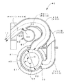
図1は、本発明の実施の一形態に係る4サイクル火花点火式多気筒エンジンの右側面図、図2は、図1のA−A断面略図である。また図3は、本実施形態の要部を簡略化して示す斜視図である。 FIG. 1 is a right side view of a four-cycle spark-ignition multi-cylinder engine according to an embodiment of the present invention, and FIG. 2 is a schematic cross-sectional view taken along line AA of FIG. FIG. 3 is a perspective view schematically showing a main part of the present embodiment.
各図を参照して、このエンジン10は、シリンダブロック11およびこのシリンダブロック11の上部に一体化されたシリンダヘッド12とを一体に有している。エンジン10には、第1〜第4気筒12A〜12Dが設けられるとともに、各気筒12A〜12Dの内部には、クランクシャフト3に連結されたピストン4が嵌挿されることにより、その上方に燃焼室15が形成されている。
Referring to the drawings, the
シリンダヘッド12には、前記各気筒12A〜12Dの燃焼室15毎に点火プラグ16が固定されている。各点火プラグ16は、その先端が対応する燃焼室15の内部に頂部から臨むように設置されている。
A
また、シリンダヘッド12には、前記気筒12A〜12D毎に燃焼室15に向かって開口する吸気ポート17、排気ポート18がそれぞれ形成されているとともに、これらのポート17、18には、吸気弁19および排気弁20がそれぞれ装備されている。
The
各吸気ポート17には燃料噴射弁21が設けられている。この燃料噴射弁21は、ニードル弁およびソレノイドを内蔵している。
Each
排気ポート18には、図略の排気マニホールドが接続されている。この排気マニホールドの集合部下流の排気通路には、排気ガス浄化触媒が設けられている。この排気ガス浄化触媒は、例えば、排気の空燃比状態が理論空燃比近傍にあるときにHC、COおよびNOxの浄化率が極めて高い、いわゆる三元触媒からなっている。この三元触媒からなる排気ガス浄化触媒は、一般に知られているように、排気ガスの空燃比が理論空燃比(つまり空気過剰率λ=1)付近にあるときにHC,CO及びNOxに対して高い浄化性能を示す触媒である。 An exhaust manifold (not shown) is connected to the exhaust port 18. An exhaust gas purification catalyst is provided in the exhaust passage downstream of the exhaust manifold assembly. This exhaust gas purification catalyst is formed of, for example, a so-called three-way catalyst in which the purification rate of HC, CO and NOx is extremely high when the air-fuel ratio of the exhaust is in the vicinity of the theoretical air-fuel ratio. As is generally known, this exhaust gas purification catalyst comprising a three-way catalyst is more effective than HC, CO, and NOx when the air-fuel ratio of the exhaust gas is near the stoichiometric air-fuel ratio (that is, the excess air ratio λ = 1). And high purification performance.
吸気弁19および排気弁20は、エンジン10に支承された吸気弁用および排気弁用のカムシャフト22、23によって、所定位相差で同期して吸気ポート17、排気ポート18を開閉するように構成されている。前記カムシャフト22、23は、図略のカムスプロケットギヤに連結され、このカムスプロケットギヤは、カムプーリ30から図略のタイミングベルトを介して動力を受けている(図3参照)。カムプーリ30は、エンジン10の前面にクランクシャフト3と平行な軸線を中心に回転自在に取り付けられている。他方、クランクシャフト3にはエンジン10の前面側に取り付けられた出力プーリ32が固定されており、両プーリ30、32は、タイミングベルト34によって同期連動するように構成されている。
The
なお、各カムシャフト22、23に対し、その回転の位相を調節することにより、開閉タイミングを変更する可変バルブタイミング機構24、25が設けられている。この結果、吸気弁19は、クランク角に対する位相を変更することができるようになっている。
The
本実施形態に係る吸気装置40は、エンジン10の側部に固定されるインテークマニホールド41と、このインテークマニホールド41に内蔵されるパルス発生装置またはPGV(Pulse Generating Valve)としてのロータリバルブ50とを有している。
The
インテークマニホールド41は、図略の支持部材を介してエンジン10に固定されており、エンジン10の前後方向(各気筒12A〜12Dが並んでいる方向)に水平に延びる集合部としてのサージタンク42と、このサージタンク42に接続され、それぞれが分離した吸気通路PH11〜PH14を形成する吸気管としての第1〜第4分岐吸気管43A〜43Dとを一体に有している。サージタンク42の後端部には、スロットルボディ44が固定されており、このスロットルボディ44の内部には、図略のスロットルバルブが内蔵されている。
The intake manifold 41 is fixed to the
サージタンク42は、略円筒形部材であり、分岐吸気管43A〜43Dと連通することによって、各分岐吸気管43A〜43Dの差圧を吸収し、異音やセンサの誤作動を防止する機能を果たすものである。本実施形態において、このサージタンク42の気筒列方向の長さSLは、次に説明する各分岐吸気管43A〜43Dの気筒列方向における下流端側の間隔DLよりも短くなるように設定されている(図1参照)。
The
各分岐吸気管43A〜43Dは、気筒12A〜12D毎に設けられ、正面視略L字形に湾曲した状態で、それぞれ対応する気筒12A〜12Dをサージタンク42と連通させている。図示の実施形態において、各分岐吸気管43A〜43Dは、その吸気通路PH11〜PH14の通路長(本実施形態においては、吸気ポート17からサージタンク42内のロータリバルブ50の周面51までの長さ)が同じ長さに設定されている。各吸気通路PH11〜PH14の長さは、500mm以内に設定されており、これによって、後述するロータリバルブ50によるトルクへのレスポンスの向上を図っている。さらに、「吸気通路/行程容積率」(各気筒の単一の行程容積に対する吸気ポート17の下流端からロータリバルブ50の開口52、53までの単一の吸気通路容積の割合)は、70パーセント以上130パーセント以下(吸気通路の通路長が500mm以下)の範囲に設定されている。この容積は、エンジンの中速運転領域(3500rpm以上)R2において、吸気が同調共鳴する固有振動数に対応するように決定される。この結果、比較的中速領域で固有振動数が同調共鳴することになるので、その領域では、吸気弁19の開弁時間を確保することができ、エンジンの中速運転領域R2で通路長設定による慣性過給効果を発揮させ、体積効率を高めることが可能になる。
Each of the
ロータリバルブ50は、円筒形部材であり、その外周面51がサージタンク42の内周面に摺接した状態で、回転自在に配置されている。
The
図3を参照して、ロータリバルブ50の前端部には、入力ギア54Aが同心に設けられている。入力ギア54Aは、前記カムプーリ30と同心に設けられた出力ギア54Bが噛合しており、この出力ギア54Bを介して、クランクシャフト3から1:0.5の比率で動力が伝達されるようになっている。換言すれば、ロータリバルブ50は、カムプーリ30と1:1の比率で同期している。このロータリバルブ50の周面には、サージタンク42の内部と分岐吸気管43A〜43Dとを連通する一対の開口52、53が形成されている。各開口52、53は、周方向に180°位相がずれており、軸方向において、前方の開口52が後方の開口53に対して、回転方向上流側にずれている。なお図において、55はアイドラである。
Referring to FIG. 3, an input gear 54 </ b> A is provided concentrically at the front end portion of the
図示の実施形態においては、ロータリバルブ50と入力ギア54Aとの間にロータリバルブ進角機構56が設けられている。このロータリバルブ進角機構56は、基本的には、本件出願人が先に提案している回転位相制御装置(特開平11−107718号公報参照)等を用いることにより、入力ギア54Aとロータリバルブ50との間に位相差を形成し、当該ロータリバルブ50の開弁タイミングを変更するための機構である。ロータリバルブ進角機構56は、図1に示すように、OCV(Oil Control Valve)システム57によって駆動制御されるようになっている。さらに、図1に示すように、ロータリバルブ50の位相を検出するために、ロータリバルブ進角機構56には、PGV角度センサ58が付設されている。
In the illustrated embodiment, a rotary
図示のエンジンは、直列4気筒エンジンであって、エンジン10の前方から順に各気筒を第1〜第4気筒12A〜12Dとするとき、吸気行程を迎える順番は、第1気筒12A、第3気筒12C、第4気筒12D、第2気筒12Bとなるように設定されている。この結果、第1気筒12Aが吸気行程を迎える時点を起点とすると、各気筒と行程の関係は、表1の通りとなる。
The illustrated engine is an in-line four-cylinder engine, and when the cylinders are first to fourth cylinders 12A to 12D in order from the front of the

そこで、本実施形態では、ロータリバルブ50の開口52に対して、第1分岐吸気管43Aを回転方向下流側、第2分岐吸気管43Bを回転方向上流側に位相をずらせて対向可能に配置するとともに、開口53に対して第3分岐吸気管43Cを回転方向上流側、第4分岐吸気管43Dを回転方向下流側に位相をずらせて対向可能に配置している。
Therefore, in the present embodiment, the first
より詳細に説明すると、第2気筒12Bに接続される第2分岐吸気管43Bと第1気筒12Aに接続される第1分岐吸気管43Aとが、前方の開口52に対向可能な位置に、上流側から順に90°位相をずらした状態でサージタンク42に固定されているとともに、第3気筒12Cに接続される第3分岐吸気管43Cと第4気筒12Dに接続される第4分岐吸気管43Dとが、後方の開口53に対向可能な位置に、上流側から順に90°位相をずらした状態でサージタンク42に固定されている。さらに、第1分岐吸気管43Aと第4分岐吸気管43D(従って、第2分岐吸気管43Bと第3分岐吸気管43C)がサージタンク42の周方向において同一位相に配置されている。従って、この構成では、エンジンの回転数に拘わらず、所定のタイミングで分岐吸気管43A〜43Dを開閉することが可能になっているとともに、各分岐吸気管43A〜43Dの等長化並びにコンパクト化に寄与することになる。この結果、吸気通路PH11〜PH14を可及的に短縮化し、トルク向上に対するレスポンスの高い吸気構造を構成することが可能になる。また、上述したように、サージタンク42の気筒列方向の長さSLは、次に説明する各分岐吸気管43A〜43Dの気筒列方向における下流端側の間隔DLよりも短くなるように設定されている(図1参照)ことと相俟って、各分岐吸気管43A〜43Dの上流端は、下流端に比べて気筒列方向に集束している。このため、本実施形態においては、極めてトルク向上に対するレスポンスが高くなる構造になっている。
More specifically, the second branch intake pipe 43B connected to the second cylinder 12B and the first
図4は図2の要部を拡大した断面図である。 FIG. 4 is an enlarged cross-sectional view of the main part of FIG.
同図を参照して、ロータリバルブ50の直径Dは、各分岐吸気管43A〜43Dの断面幅よりも大きく設定されている。このロータリバルブ50をクランクシャフト3と同期させて回転させることにより、各開口52、53が対応する分岐吸気管43A〜43Dを開く時間も短くなる。またロータリバルブ50が回転によって、周面に形成された開口52、53によって、当該周面に臨む分岐吸気管43A〜43Dに空気を供給するものであるので、空気の脈動を抑制することができ、異音の発生も少なくなる。
With reference to the figure, the diameter D of the
さらに、ロータリバルブ50に形成された各開口52、53間の閉弁角度θは、例えば120°に設定されており、開弁開始タイミングを吸気行程の前半部分とすることにより、吸気弁19が吸気ポート17を開いてもロータリバルブ50がサージタンク42を遮蔽した状態になるので、ロータリバルブ50が開くまでの間、吸気行程によって、対応する分岐吸気管43A(〜43D)内に負圧が生じることになる。
Furthermore, the valve closing angle θ between the
図5は図1の要部を拡大して示す部分拡大図である。 FIG. 5 is a partially enlarged view showing an essential part of FIG.
図4および図5を参照して、各分岐吸気管43A〜43Dには、VIS(Valuable Induction System)60が設けられている。
Referring to FIGS. 4 and 5, each
VIS60は、クランクシャフト3と平行に延びる容積部としての容積管61と、この容積管61と各分岐吸気管43A〜43Dとを接続する連通管62と、連通管62を開閉する開閉機構としてのVISバルブ63とを有している。図示の例において、容積管61は、各分岐吸気通路43A〜43Dを連通する連通路としても機能する部材である。各VISバルブ63は、同一の駆動軸64に連結されており、駆動軸64を駆動するVISバルブアクチュエータ65によって、一斉に開閉駆動されるように構成されている。図示の実施形態において、各吸気ポート17の下流端から前記容積管61までの吸気通路長Lfは、第1の所定回転数(例えば4500rpm)Nf以上の高速運転領域R3で動的過給(この実施形態では、慣性過給)できる長さに設定されている。他方、各吸気ポート17の下流端からロータリバルブ50までの吸気通路長Lsは、第1の所定回転数Nfよりも少ない第2の所定回転数(例えば3800rpm)Ns以上の中速運転領域R2で動的過給(この実施形態では、慣性過給)できる長さに設定されている。この結果、各分岐吸気管43A〜43Dは、VISバルブアクチュエータ65がVISバルブ63を開いた状態では、第1の所定回転数Nfで吸気が同調共鳴する固有振動数に対応し、高速運転領域R3での慣性過給効果を高めることができるとともに、VISバルブアクチュエータ65がVISバルブ63を閉じた状態では、第2の所定回転数Nsで吸気が同調共鳴する固有振動数に対応し、中速運転領域R2での慣性過給効果を高めることができるようになっている。
The VIS 60 is a volume tube 61 as a volume portion extending in parallel with the
図2を参照して、エンジン10には、一対のエンジンクランク角度センサ66が設けられている。各エンジンクランク角度センサ66は、所定の位相差をもってクランクシャフト3の周囲に配置されており、一方のエンジンクランク角度センサ66から出力される検出信号に基づいてエンジンの回転数が検出されるとともに、両エンジンクランク角度センサ66から出力される検出信号に基づいてクランクシャフト3の回転方向および回転角度が検出されるようになっている。さらに、エンジン10の運転状態を検出するために、エンジン10の冷却水の温度を検出するエンジン水温センサ67、エンジン負荷検出手段としてのアクセル開度センサ68、および排気ポート18から排出された排気ガスの酸素量を検出するO2センサ69が設けられている。
With reference to FIG. 2, the
また、排気ポート18に排出された既燃ガスの一部を吸気ポート17に還流するためのEGRシステム70が設けられている。
Further, an
図6は本実施形態に係るブロック図である。 FIG. 6 is a block diagram according to the present embodiment.
同図を参照して、エンジン10を駆動制御するためのECU100は、マイクロプロセッサ、メモリ、入力部および出力部を有しているユニットである。このECU100の入力部には、ロータリバルブ50の位相を検出するPGV角度センサ58、エンジンクランク角度センサ66、エンジン水温センサ67、アクセル開度センサ68、O2センサ69が入力要素として接続されている。また、ECU100の出力部には、点火プラグ16、燃料噴射弁21、吸気弁19および排気弁20の可変バルブタイミング機構24、25、ロータリバルブ進角機構56(具体的にはOCVシステム57)、およびVISバルブアクチュエータ65が出力要素として接続されている。
Referring to FIG. 1,
次に、ECU100のメモリに記憶されている制御マップについて説明する。
Next, a control map stored in the memory of the
図7はエンジン回転数Nに対するトルク、ロータリバルブ50の位相、およびVISバルブ63の開閉動作を示すグラフである。
FIG. 7 is a graph showing the torque with respect to the engine speed N, the phase of the
図7を参照して、エンジンの出力特性は、ロータリバルブ50を用いた場合、トルクの特性は、曲線C1のようになる。また、VISバルブ63を閉じたときのトルクの特性、すなわち、各分岐吸気管43A〜43Dの吸気通路長がLsのときは、曲線C2のようになる。さらに、VISバルブ63を開いたときのトルクの特性、すなわち、各分岐吸気管43A〜43Dの吸気通路長がLfのときは、曲線C3のようになる。そこで、運転領域をロータリバルブ50によって過給する低速運転領域をR1、吸気通路長をLsとして慣性過給を生じさせる中速運転領域をR2、吸気通路長をLfとして慣性過給を生じさせる高速運転領域をR3と設定し、予め実験等でVISバルブ63を閉じるときのエンジン回転数を第1の所定回転数Nfとし、これよりも低いエンジン回転数を第2の所定回転数Nsとして、図7に基づく制御マップを作成し、ECU100のメモリに記憶させている。
Referring to FIG. 7, when the
ところで、低速運転領域R1においても、必ずしもロータリバルブ50を作動させることが得策でない場合もある。
By the way, even in the low speed operation region R1, it may not always be a good idea to operate the
図8はトルクと燃費の関係を示すグラフである。 FIG. 8 is a graph showing the relationship between torque and fuel consumption.
図8を参照して、ロータリバルブ50が作動している場合、ポンピングロスが増加することに伴い、ロータリバルブ50が作動していない場合よりも燃費は悪くなる。このため、エンジン10の部分負荷領域においては、低速運転領域R1であってもVISバルブ63を開いて、燃費の向上を図り、高負荷領域(エンジン全開領域)でのみロータリバルブ50による過給効果が得られるようにECU100が設定されている。
Referring to FIG. 8, when the
次に、上述した実施形態の動作について、図9以下のフローチャートを参照しながら説明する。 Next, the operation of the above-described embodiment will be described with reference to the flowcharts in FIG.
図9を参照して、以上の構成では、まず、エンジン10が始動を開始した後(ステップS1)、ECU100は、入力部に接続された入力要素から各検出値を読み込む(ステップS2)。
Referring to FIG. 9, in the above configuration, first, after
次いで、これらの検出値に基づき、PGVとしてのロータリバルブ50の目標値を設定する(ステップS3)。図示の実施形態において、エンジン始動時のロータリバルブ50の位相は、最進角した状態(すなわちOFFの状態)に設定されている。この状態でECU100は、ロータリバルブ進角機構56のOCVシステム57を制御し、ロータリバルブ50の開弁タイミングを決定する。図7に示されているように、ロータリバルブ50は、低速側では、遅角(吸気弁19の開弁タイミングに対して最も開弁タイミングが遅れる状態)に設定されている一方、エンジン回転数Nが上昇するに連れて進角(吸気弁19の開弁タイミングに対して開弁タイミングが近づく状態)するように構成されている。
Next, a target value of the
次に、ECU100は、エンジン回転数Nが第2の所定回転数Nsに到達しているか否かを検出する(ステップS4)。仮にエンジン回転数Nが第2の所定回転数Nsに満たない場合、ECU100は、低速運転領域R1にてエンジン10が運転しているものと判定し、さらにアクセル開度から部分負荷領域であるか否かを判定する(ステップS5)。仮に運転状態が部分負荷領域である場合、ECU100は、VISバルブ63を作動させるためのフラグFを参照する(ステップS6)。フラグFのドメインは、VISバルブ63を閉じる値を0、開く値を1として二者択一的に設定されている。ステップS6において、フラグFの値が0の場合、ECU100は、VISバルブ63を開く(ステップS7)。ここで、ロータリバルブ50の運転を停止するための手段として、本実施形態のステップS7では、ロータリバルブ進角機構56を直接制御するのではなく、VISバルブ63を開いて、容積管61を介し各分岐吸気管43A〜43Dを連通させる方法を採用しているので、イナーシャや空気抵抗の大きいロータリバルブ50を直接駆動する場合に比べて、高い応答性を発揮することが可能になる。これにより、ロータリバルブ50によるインパルス生成による過給効果が解除され、燃費の向上を図ることが可能になる。
Next, the
その後、ECU100はフラグFの値を1に更新する(ステップS8)。また、ステップS6において、フラグFの値が1の場合には、そのまま次のステップに進む。
Thereafter, the
ステップS4において、エンジン回転数が第2の所定回転数Ns以上であった場合、ECU100は、ロータリバルブ50の停止設定を行う(ステップ9)。つまり、図7にも示すように、第2の所定回転数Ns以上では、吸気行程期間中にロータリバルブ50が開くようにロータリバルブ50の開弁タイミングを進角させる。
In step S4, when the engine speed is equal to or higher than the second predetermined speed Ns, the
次いで、ECU100は、エンジン回転数Nが第1の所定回転数Nf未満であるか否かを判別する(ステップS10)。仮にエンジン回転数Nが第1の所定回転数Nf以上であった場合、ECU100は、エンジン10が高速運転領域R3で運転しているものと判定し、ステップS6に移行する。このため、高速運転領域R3では、VISバルブ63が開くことに伴い、各分岐吸気管43A〜43Dでは、高速運転領域R3に適した短い吸気通路長Lfで動的過給(慣性過給)効果を得ることができる。
Next, the
他方、ステップS5において、運転状態が全負荷領域であった場合、またはステップS10において、エンジン回転数Nが第1の所定回転数Nfに満たない場合、ECU100はフラグFの値が1であるか否かを参照し(ステップS11)、フラグFの値が1である場合には、VISバルブ63を閉じて(ステップS12)、フラグFの値を0に更新する(ステップS13)。また、フラグFの値が0である場合には、そのまま次のステップに移行する。
On the other hand, if the operating state is the full load range in step S5, or if the engine speed N is less than the first predetermined speed Nf in step S10, the
図10を参照して、図9のフローが終了した後、ECU100は、当該フローのステップS3またはステップS9における設定に基づいて、ロータリバルブ50を運転する(ステップS14)。この場合、ステップS9の設定に基づく運転状態では、ロータリバルブ50は実質的に停止していることになる。また、エンジン回転数Nが第1の所定回転数Nf以上のときは、VISバルブ63が開いており、ロータリバルブ50は、その開閉タイミングに拘わらず実質的に停止している。その後は、所定時期で設定期間、燃料噴射弁21を駆動して、燃料を噴射し(ステップS15)、さらに所定時期で点火プラグ16を駆動して燃焼室15内の混合気を燃焼させる(ステップS16)。その後、ECU100は、エンジン10が運転を停止した場合には、処理を終了し、運転を継続している場合には、ステップS2に戻る(ステップS17)。
Referring to FIG. 10, after the flow of FIG. 9 is completed,
以上説明したように、本実施形態においては、エンジン回転数Nが第1の所定回転数Nf以上の高速運転領域R3では、VISバルブ63が開いて容積管61を分岐吸気管43A〜43Dと連通することにより、各分岐吸気管43A〜43Dにおける吸気ポート17の下流端から前記容積管61までの間に慣性過給を生じさせることが可能になる。このため、高速運転領域R3での体積効率が向上する。次に、この第1の所定回転数Nfから第2の所定回転数Nsまでの中速運転領域R2では、VISバルブ63が容積管61を閉じることにより、各分岐吸気管43A〜43Dの吸気ポート17下流端から前記サージタンク42までの間に慣性過給を生じさせることが可能になる。このため、中速回転域での体積効率が向上する。さらに、前記第2の所定回転数Nsにも満たない低速運転領域R1では、容積管61が閉じたままの状態でロータリバルブ50が作動することにより、分岐吸気管43A〜43Dにインパルスを生成することができる。このため、低速運転領域R1での体積効率が向上する。
As described above, in the present embodiment, in the high speed operation region R3 where the engine speed N is equal to or higher than the first predetermined speed Nf, the VIS valve 63 is opened and the volume pipe 61 is communicated with the
また、本実施形態において、前記ECU100は、少なくとも第2の所定回転数Nsから第1の所定回転数Nfまでの中速運転領域R2では、ロータリバルブ50の作動を停止するものである。このため本実施形態では、中高速運転領域R2、R3においては、インパルスが生成されなくなり、容積管61またはサージタンク42を設けたことによる吸気通路の慣性過給を積極利用することが可能になる。
In the present embodiment, the
また、本実施形態において、前記容積管61は、各分岐吸気管43A〜43Dを連通する連通路で構成されている。このため本実施形態では、容積管61を開閉するVISバルブ63の開閉動作によって吸気通路長を確実に切換えることができるので、中高速運転領域R2、R3における各分岐吸気管43A〜43Dによる慣性過給を積極利用することが可能になる。
Further, in the present embodiment, the volume pipe 61 is constituted by a communication path that communicates the branched
また、本実施形態では、エンジン負荷を検出してECU100に入力するエンジン負荷検出手段としてのアクセル開度センサ68を設け、前記ECU100は、部分負荷領域では、第2の所定回転数Ns以下でも容積管61を開くものである。このため本実施形態では、エンジン10が高負荷である全開運転領域では、ロータリバルブ50による過給効果によって、高い体積効率を得ることができる一方、それ以外の部分負荷領域では、容積管61が開くことによって、ロータリバルブ50によるインパルス生成効果を迅速に解除し、燃費の向上を図ることが可能になる。特に、容積管61が各分岐吸気管43A〜43Dを連通する連通路で構成されていることと相俟って、ロータリバルブ50による筒内圧力を迅速に高めることが可能になる。このため、エンジン回転数Nが低い低速運転領域R1において、大きな出力を必要としない部分負荷領域では、ロータリバルブ50によるポンピングロスを低減し、燃費を向上することが可能になる。
Further, in the present embodiment, an
また、本実施形態において、前記ロータリバルブ50は、開弁タイミングを変更可能な可変開弁機構としてのロータリバルブ進角機構56を有し、前記ECU100は、エンジン回転数Nが第2の所定回転数Nsに近づくに連れてロータリバルブ50の開弁タイミングを進角させる(吸気弁19の開弁タイミングに近づける)ようにロータリバルブ進角機構56を制御するものである。このため本実施形態では、エンジン回転数Nが第2の所定回転数Nsに上昇するに連れて、ロータリバルブ50の開弁タイミングが吸気弁19の開弁タイミングに近づくので、生成されるインパルスも弱まり、高速側におけるポンピングロスを低減し、燃費の向上を図ることができる。また、生成されるインパルスが弱まることにより、相対的に分岐吸気管43A〜43D内での慣性過給を高めることになり、筒内の体積効率を高い状態に維持することが可能になる。
Further, in the present embodiment, the
本実施形態において、前記パルス発生装置は、前記サージタンク42内に収容され、エンジン10のクランクシャフト3と同期して回転するロータリバルブ50である。このため本実施形態では、大きな吸気抵抗を受けることなく、周波数を確実に同調させて所望のタイミングで気筒内にインパルスを生成することが可能になる。サージタンク42または容積管61を設けることによる慣性過給を阻害することなく、インパルスを生成するロータリバルブ50を装備することが可能になる。
In the present embodiment, the pulse generator is a
また、本実施形態においては、前記ロータリバルブ50の径を分岐吸気管43A〜43D断面幅より大きく設定するとともに、各分岐吸気管43A〜43Dの上流端は、ロータリバルブ50の周面に形成された開口52、53に臨んで、選択的に開閉されるように配置され、各気筒12A〜12Dの単一の行程容積に対する吸気ポート17の下流端からロータリバルブ50の前記開口52、53までの単一の独立吸気通路容積の割合が70パーセントから130パーセントの範囲に設定されている。このため本実施形態では、分岐吸気管43A〜43Dに対して速い周速で開閉動作を行ない、強いインパルスを発生させることができる。さらに、このロータリバルブ50は、各気筒12A〜12Dの単一の行程容積に対する吸気ポート17の下流端からロータリバルブ50の前記開口までの単一の独立吸気通路容積の割合を70パーセントから130パーセントの範囲となる位置に設定されている。この設定範囲は、本件発明者が鋭意研究の結果、シミュレーションによって見出した範囲であり、後述するように、例えば3500rpmでの体積効率を約90%以上に向上することができる範囲である。
In the present embodiment, the diameter of the
各気筒12A〜12Dの単一の行程容積に対する吸気ポート17の下流端からロータリバルブ50の前記開口までの単一の吸気通路容積の割合、すなわち吸気通路/行程容積率が130パーセントを超えたとしても、体積効率は、必ずしも低下しない。しかし、その場合には、吸気通路が長くなるため、トルク向上に対するレスポンスが低下する傾向を持つ。そのため、定常的な走行時のトルクを高くすることができたとしても、加速時の過渡的な状態では、必ずしもトルクを向上させることができなくなる恐れがある。他方、吸気通路/行程容積率が70パーセントを下回った場合、今度は、気筒に必要な空気量を確保することができなくなるため、レスポンスは高くなるものの、体積効率は低下する。そこで、本実施形態では、吸気通路/行程容積率を70パーセントから130パーセントに設定している。この結果、定常時のトルクはもちろん、加速時の過渡的な状態でのトルクも効率よく高めることが可能になる。
The ratio of the single intake passage volume from the downstream end of the
この点に関し、行程容積と吸気通路容積との関係について説明する。 In this regard, the relationship between the stroke volume and the intake passage volume will be described.
本件発明者は、上述した実施形態の吸気装置40を構成するに当たり、表2の仕様のシリンダで当該シリンダの行程容積と分岐管の容積との関係についてシミュレーションを行った。
The present inventor performed a simulation on the relationship between the stroke volume of the cylinder and the volume of the branch pipe in the cylinder of the specification shown in Table 2 when configuring the
表2において、吸気通路長は、吸気ポート17と分岐管(分岐吸気管43A〜43D)の通路長さの和であり、具体的には、吸気ポート17の燃焼室5に対する開口端(下流端)からロータリバルブ50の開口52(53)までの長さである(図2参照)。行程容積Vhは、シリンダ14のピストン上死点からピストン下死点までの容積であり、吸気通路容積Vは、シリンダヘッド12に形成された吸気ポート17の容積と分岐管(分岐吸気管43A〜43D)の容積の和である。
In Table 2, the intake passage length is the sum of the passage lengths of the
図11は、本仕様で体積効率ηvと回転数Nの関係を示したグラフである。 FIG. 11 is a graph showing the relationship between the volumetric efficiency ηv and the rotational speed N in this specification.
図11の測定結果は、吸気通路長が250mmの場合(T3の場合)をベースとして、ロータリバルブ50を115°CAで開いたときの吸気弁19の開閉範囲が50°CA/30°CAから10°CA/70°CAのときの最高値を示したものである。
The measurement results in FIG. 11 are based on the case where the intake passage length is 250 mm (in the case of T3), and the opening / closing range of the
同図に示すように、吸気通路/行程容積率が低い場合、吸気通路/行程容積率が70パーセントを下回ると、図のT1で示すように、全体的に体積効率ηvが低くなり、特に3500rpmの体積効率ηvが大きく落ち込んでしまう。これは、吸気通路容積Vが小さすぎるため、ロータリバルブによるパルス発生作用によっても充分な空気量を確保することができないこと、並びにパルス発生時に低速運転領域(2500rpmの範囲)R1と高速運転領域(4500rpm〜5500rpm)R3がピーキーになり、3500rpmのところで谷ができてしまうことによるものと考えられる。他方、吸気通路長がベース長さよりも長い場合(吸気通路/行程容積率が96パーセント以上の場合)には、高速運転領域R3でのピークが緩和される結果、低速運転領域R1での体積効率ηvが高くなっても、3500rpmの谷が小さくなる傾向となることがわかった。尤も、吸気通路長が長くなると、吸気のレスポンスも悪くなる結果、加速時の過渡的なトルクが小さくなる恐れがある。これらの観点から、吸気通路/行程容積率が70パーセント以上130パーセント以下(吸気通路長さが500mm以下)である場合には、定常時、過渡時の双方において高トルクを得ることができ、しかも、レスポンスも向上することがわかった。 As shown in the figure, when the intake passage / stroke volume ratio is low and the intake passage / stroke volume ratio falls below 70%, the overall volume efficiency ηv decreases as shown by T1 in the figure, particularly 3500 rpm. The volumetric efficiency ηv is greatly reduced. This is because the intake passage volume V is too small, so that a sufficient amount of air cannot be secured even by the pulse generation action by the rotary valve, and the low speed operation region (range 2500 rpm) R1 and the high speed operation region ( 4500 rpm to 5500 rpm) It is considered that R3 becomes peaky and a valley is formed at 3500 rpm. On the other hand, when the intake passage length is longer than the base length (when the intake passage / stroke volume ratio is 96% or more), the peak efficiency in the high-speed operation region R3 is alleviated, resulting in volumetric efficiency in the low-speed operation region R1. It was found that the valley at 3500 rpm tends to decrease even when ηv increases. However, if the intake passage length is increased, the response of intake air is also deteriorated, so that the transient torque during acceleration may be reduced. From these viewpoints, when the intake passage / stroke volume ratio is 70% or more and 130% or less (the intake passage length is 500 mm or less), a high torque can be obtained both in the steady state and in the transient state. It was found that the response was improved.
さらに本実施形態において、前記吸気通路長Lfは、前記高速運転領域R3で慣性過給できる長さに設定されており、前記吸気通路長Lsは、前記中速運転領域R2で慣性過給できる長さに設定されている。このため本実施形態では、各吸気通路長Lf、Lsを短く設定することができるので、吸気系のコンパクト化を図ることが可能になる。 Further, in the present embodiment, the intake passage length Lf is set to a length that allows inertia supercharging in the high speed operation region R3, and the intake passage length Ls is a length that allows inertia supercharging in the medium speed operation region R2. Is set. For this reason, in this embodiment, since the intake passage lengths Lf and Ls can be set short, the intake system can be made compact.
このように本実施形態によれば、全ての運転領域R1〜R3において、好適な過給効果を得られるので、運転領域R1〜R3に応じて燃費と出力とをバランスさせることができるという顕著な効果を奏する。 Thus, according to this embodiment, since a suitable supercharging effect can be obtained in all the driving regions R1 to R3, the fuel efficiency and the output can be balanced according to the driving regions R1 to R3. There is an effect.
上述した実施形態は、本発明の好ましい具体例に過ぎず、本発明は上述した実施形態に限定されない。 The above-described embodiments are merely preferred specific examples of the present invention, and the present invention is not limited to the above-described embodiments.
本発明の特許請求の範囲内で種々の変更が可能であることはいうまでもない。 It goes without saying that various modifications are possible within the scope of the claims of the present invention.
10 エンジン
12A〜12D 気筒
15 燃焼室
16 点火プラグ
17 吸気ポート
19 吸気弁
21 燃料噴射弁
40 吸気装置
41 インテークマニホールド
42 サージタンク(集合部)
43A〜43D 分岐吸気管
50 ロータリバルブ(PGV:パルス発生装置)
52 開口
53 開口
56 ロータリバルブ進角機構(可変開弁機構)
57 OCVシステム(可変開弁機構)
58 PGV角度センサ
61 容積管(容積部)
63 VISバルブ(容積部開閉機構)
65 バルブアクチュエータ(容積部開閉機構)
66 エンジンクランク角度センサ
68 アクセル開度センサ
69 O2センサ
Lf 吸気通路長
Ls 吸気通路長
N エンジン回転数
Nf 第1の所定回転数
Ns 第2の所定回転数
PH11〜PH14 吸気通路
R1 低速運転領域
R2 中速運転領域
R3 高速運転領域
θ 開口角度
DESCRIPTION OF
43A to 43D
52
57 OCV system (variable valve opening mechanism)
58 PGV angle sensor 61 Volumetric tube (volume part)
63 VIS valve (volume part opening and closing mechanism)
65 Valve actuator (volume part opening / closing mechanism)
66 Engine crank
Claims (8)
各気筒の吸気行程に対応して、吸気ポートの開弁期間内の吸気行程途中で開弁して、気筒内に圧力波を生成するパルス発生装置と
を備えた多気筒エンジンの制御装置において、
エンジンの回転数を検出するエンジン回転数検出手段と、
前記吸気管に連通する容積部と、
容積部と吸気管との連通部分を開閉する容積部開閉機構と、
前記エンジン回転数検出手段の検出に基づいてパルス発生装置の運転および容積部開閉機構の開閉動作を制御する制御手段と
を設け、
各吸気管の吸気ポート下流端から前記容積部までの吸気通路長は、第1の所定回転数以上の高速運転領域で動的過給できる長さに設定し、
各吸気管の吸気ポート下流端から前記集合部までの吸気通路長は、前記第1の所定回転数よりも少ない第2の所定回転数以上の中速運転領域で動的過給できる長さに設定し、
前記制御手段は、前記第1の所定回転数以上では、容積部を開くように容積部開閉機構を制御するとともに、前記第2の所定回転数に満たない運転領域では、パルス発生装置を作動させるものであることを特徴とする多気筒エンジンの制御装置。 An intake pipe that supplies air to each intake port of a plurality of cylinders, and a collecting portion that opens at the upstream end of each intake pipe,
In a control apparatus for a multi-cylinder engine that includes a pulse generator that generates a pressure wave in a cylinder by opening the valve in the middle of the intake stroke during the valve opening period of the intake port corresponding to the intake stroke of each cylinder.
Engine speed detecting means for detecting the engine speed;
A volume communicating with the intake pipe;
A volume opening and closing mechanism for opening and closing a communicating portion between the volume and the intake pipe;
Control means for controlling the operation of the pulse generator and the opening / closing operation of the volume opening / closing mechanism based on the detection of the engine speed detection means,
The intake passage length from the intake port downstream end of each intake pipe to the volume portion is set to a length that can be dynamically supercharged in a high-speed operation region equal to or higher than the first predetermined rotation speed,
The length of the intake passage from the downstream end of the intake port of each intake pipe to the collecting portion is a length that allows dynamic supercharging in a medium speed operation region that is less than the first predetermined rotational speed and is equal to or higher than a second predetermined rotational speed. Set,
The control means controls the volume portion opening / closing mechanism so as to open the volume portion at the first predetermined rotation speed or more, and operates the pulse generator in an operation region that does not satisfy the second predetermined rotation speed. A control device for a multi-cylinder engine,
前記制御手段は、少なくとも第2の所定回転数から第1の所定回転数までの運転領域では、パルス発生装置の作動を停止するものであることを特徴とする多気筒エンジンの制御装置。 The control apparatus for a multi-cylinder engine according to claim 1,
The control device for a multi-cylinder engine, wherein the control means stops the operation of the pulse generator at least in an operation region from a second predetermined rotation speed to a first predetermined rotation speed.
前記容積部は、各吸気管を連通する連通路で構成されていることを特徴とする多気筒エンジンの制御装置。 The control apparatus for a multi-cylinder engine according to claim 2,
The control unit for a multi-cylinder engine, wherein the volume part is configured by a communication path that communicates each intake pipe.
エンジン負荷を検出して制御手段に入力するエンジン負荷検出手段を設け、前記制御手段は、部分負荷領域では、第2の所定回転数以下でも容積部を開くものであることを特徴とする多気筒エンジンの制御装置。 The control apparatus for a multi-cylinder engine according to claim 3,
An engine load detecting means for detecting an engine load and inputting the engine load to the control means is provided, and the control means opens the volume portion even at a second predetermined rotation speed or less in the partial load region. Engine control device.
前記パルス発生装置は、開弁タイミングを変更可能な可変開弁機構を有し、前記制御手段は、エンジン回転数が第2の所定回転数に近づくに連れてパルス発生装置の開弁タイミングを進角させるように可変開弁機構を制御するものであることを特徴とする多気筒エンジンの制御装置。 The multi-cylinder engine control device according to any one of claims 1 to 4,
The pulse generator has a variable valve opening mechanism capable of changing a valve opening timing, and the control means advances the valve opening timing of the pulse generator as the engine speed approaches a second predetermined speed. A control device for a multi-cylinder engine, which controls a variable valve opening mechanism so as to make it turn.
前記パルス発生装置は、前記集合部内に収容され、エンジンのクランクシャフトと同期して回転するロータリバルブであることを特徴とする多気筒エンジンの制御装置。 The multi-cylinder engine control device according to any one of claims 1 to 5,
The control device for a multi-cylinder engine, wherein the pulse generator is a rotary valve that is housed in the collecting portion and rotates in synchronization with a crankshaft of the engine.
前記パルス発生装置は、クランクシャフトと同期して回転するロータリバルブであって、このロータリバルブの径を吸気管断面幅より大きく設定するとともに、各吸気管の上流端は、ロータリバルブの周面に形成された開口に臨んで、選択的に開閉されるように配置され、各気筒の単一の行程容積に対する吸気ポートの下流端からロータリバルブの前記開口までの単一の独立吸気通路容積の割合が70パーセントから130パーセントの範囲に設定されていることを特徴とする多気筒エンジンの制御装置。 The multi-cylinder engine control device according to any one of claims 1 to 6,
The pulse generator is a rotary valve that rotates in synchronization with the crankshaft. The diameter of the rotary valve is set to be larger than the cross-sectional width of the intake pipe, and the upstream end of each intake pipe is located on the circumferential surface of the rotary valve. The ratio of the single independent intake passage volume from the downstream end of the intake port to the opening of the rotary valve with respect to the single stroke volume of each cylinder, arranged to be selectively opened and closed facing the formed opening Is set in the range of 70 percent to 130 percent.
各吸気管の吸気ポート下流端から前記容積部までの吸気通路長は、前記高速運転領域で慣性過給できる長さに設定されており、各吸気管の吸気ポート下流端から前記集合部までの吸気通路長は、前記中速運転領域で慣性過給できる長さに設定されているものであることを特徴とする多気筒エンジンの制御装置。 The control apparatus for a multi-cylinder engine according to any one of claims 1 to 7,
The intake passage length from the intake port downstream end of each intake pipe to the volume portion is set to a length that allows inertia supercharging in the high-speed operation region, and from the intake port downstream end of each intake pipe to the collecting portion. The multi-cylinder engine control apparatus is characterized in that the intake passage length is set to a length that allows inertia supercharging in the medium speed operation region.
Priority Applications (3)
| Application Number | Priority Date | Filing Date | Title |
|---|---|---|---|
| JP2005083659A JP4507933B2 (en) | 2005-03-23 | 2005-03-23 | Multi-cylinder engine controller |
| EP06006015A EP1705351B1 (en) | 2005-03-23 | 2006-03-23 | Control apparatus of multi-cylinder engine |
| DE602006019512T DE602006019512D1 (en) | 2005-03-23 | 2006-03-23 | Control device of a multi-cylinder internal combustion engine |
Applications Claiming Priority (1)
| Application Number | Priority Date | Filing Date | Title |
|---|---|---|---|
| JP2005083659A JP4507933B2 (en) | 2005-03-23 | 2005-03-23 | Multi-cylinder engine controller |
Publications (2)
| Publication Number | Publication Date |
|---|---|
| JP2006266134A JP2006266134A (en) | 2006-10-05 |
| JP4507933B2 true JP4507933B2 (en) | 2010-07-21 |
Family
ID=37202371
Family Applications (1)
| Application Number | Title | Priority Date | Filing Date |
|---|---|---|---|
| JP2005083659A Expired - Fee Related JP4507933B2 (en) | 2005-03-23 | 2005-03-23 | Multi-cylinder engine controller |
Country Status (1)
| Country | Link |
|---|---|
| JP (1) | JP4507933B2 (en) |
Citations (4)
| Publication number | Priority date | Publication date | Assignee | Title |
|---|---|---|---|---|
| JPS6365141A (en) * | 1986-09-08 | 1988-03-23 | Mazda Motor Corp | Engine with fuel injection device |
| JPH0388914A (en) * | 1989-08-31 | 1991-04-15 | Mitsubishi Motors Corp | Electronic control system for rotary valve in engine suction line |
| JP2003193845A (en) * | 2001-12-03 | 2003-07-09 | Filterwerk Mann & Hummel Gmbh | Intake device for impulse supercharging internal combustion engine |
| JP2006112381A (en) * | 2004-10-18 | 2006-04-27 | Nissan Motor Co Ltd | Intake control device of engine |
-
2005
- 2005-03-23 JP JP2005083659A patent/JP4507933B2/en not_active Expired - Fee Related
Patent Citations (4)
| Publication number | Priority date | Publication date | Assignee | Title |
|---|---|---|---|---|
| JPS6365141A (en) * | 1986-09-08 | 1988-03-23 | Mazda Motor Corp | Engine with fuel injection device |
| JPH0388914A (en) * | 1989-08-31 | 1991-04-15 | Mitsubishi Motors Corp | Electronic control system for rotary valve in engine suction line |
| JP2003193845A (en) * | 2001-12-03 | 2003-07-09 | Filterwerk Mann & Hummel Gmbh | Intake device for impulse supercharging internal combustion engine |
| JP2006112381A (en) * | 2004-10-18 | 2006-04-27 | Nissan Motor Co Ltd | Intake control device of engine |
Also Published As
| Publication number | Publication date |
|---|---|
| JP2006266134A (en) | 2006-10-05 |
Similar Documents
| Publication | Publication Date | Title |
|---|---|---|
| JP4305477B2 (en) | Spark ignition internal combustion engine | |
| JP4168872B2 (en) | Control device for internal combustion engine | |
| JP4367439B2 (en) | Spark ignition internal combustion engine | |
| JP5141828B2 (en) | Spark ignition internal combustion engine | |
| JP5310747B2 (en) | Spark ignition internal combustion engine | |
| JP6327263B2 (en) | Control device for internal combustion engine | |
| JP3937522B2 (en) | Variable valve operating device for internal combustion engine | |
| EP1705351B1 (en) | Control apparatus of multi-cylinder engine | |
| JP4483644B2 (en) | Multi-cylinder engine controller | |
| JP4645252B2 (en) | Multi-cylinder engine controller | |
| JP4507933B2 (en) | Multi-cylinder engine controller | |
| JP2009293567A (en) | Valve control device for internal combustion engine | |
| JP4569338B2 (en) | Multi-cylinder engine controller | |
| JP4483643B2 (en) | Multi-cylinder engine controller | |
| JP4466278B2 (en) | Multi-cylinder engine intake system | |
| JP2010084532A (en) | Valve timing variable device for engine | |
| EP1705349B1 (en) | Control apparatus of multi-cylinder engine | |
| JP4561445B2 (en) | Multi-cylinder engine intake system | |
| JP2013238124A (en) | Internal combustion engine including variable compression ratio mechanism | |
| JP4517772B2 (en) | Multi-cylinder engine intake system | |
| JP4385585B2 (en) | Internal combustion engine | |
| JP5157672B2 (en) | Multi-cylinder engine air-fuel ratio control method | |
| JP2006266138A (en) | Controller of multi-cylinder engine | |
| JP2006283570A (en) | Control device of multi-cylinder engine | |
| JP5287278B2 (en) | Fuel injection control device for hybrid vehicle |
Legal Events
| Date | Code | Title | Description |
|---|---|---|---|
| A621 | Written request for application examination |
Free format text: JAPANESE INTERMEDIATE CODE: A621 Effective date: 20080117 |
|
| TRDD | Decision of grant or rejection written | ||
| A01 | Written decision to grant a patent or to grant a registration (utility model) |
Free format text: JAPANESE INTERMEDIATE CODE: A01 Effective date: 20100413 |
|
| A01 | Written decision to grant a patent or to grant a registration (utility model) |
Free format text: JAPANESE INTERMEDIATE CODE: A01 |
|
| A61 | First payment of annual fees (during grant procedure) |
Free format text: JAPANESE INTERMEDIATE CODE: A61 Effective date: 20100426 |
|
| FPAY | Renewal fee payment (event date is renewal date of database) |
Free format text: PAYMENT UNTIL: 20130514 Year of fee payment: 3 |
|
| R150 | Certificate of patent or registration of utility model |
Ref document number: 4507933 Country of ref document: JP Free format text: JAPANESE INTERMEDIATE CODE: R150 Free format text: JAPANESE INTERMEDIATE CODE: R150 |
|
| FPAY | Renewal fee payment (event date is renewal date of database) |
Free format text: PAYMENT UNTIL: 20140514 Year of fee payment: 4 |
|
| LAPS | Cancellation because of no payment of annual fees |