JP4495548B2 - Lottery equipment - Google Patents
Lottery equipment Download PDFInfo
- Publication number
- JP4495548B2 JP4495548B2 JP2004244850A JP2004244850A JP4495548B2 JP 4495548 B2 JP4495548 B2 JP 4495548B2 JP 2004244850 A JP2004244850 A JP 2004244850A JP 2004244850 A JP2004244850 A JP 2004244850A JP 4495548 B2 JP4495548 B2 JP 4495548B2
- Authority
- JP
- Japan
- Prior art keywords
- rolling element
- lottery
- winning
- ball
- game
- Prior art date
- Legal status (The legal status is an assumption and is not a legal conclusion. Google has not performed a legal analysis and makes no representation as to the accuracy of the status listed.)
- Expired - Fee Related
Links
Images


Description
本願発明は、たとえばメダルゲーム機に用いられる抽選装置に関する。 The present invention relates to a lottery device used for a medal game machine, for example.
いわゆるアーケード型のメダルゲーム機としては、メダルを所定のフィールドに投入させてゲームを行なわせるものがある。このようなメダルゲーム機においては、メダルを用いて単純なゲームを進行させるだけではなく、たとえばボールを利用した抽選ゲームを行なわせることにより、ゲームを複雑化し、その趣向性を高めるようにしたものがある(たとえば、特許文献1,2を参照)。 Some so-called arcade-type medal game machines have a medal inserted into a predetermined field to play a game. In such a medal game machine, not only a simple game is advanced using medals, but also a lottery game using a ball is performed, for example, so that the game is complicated and its preference is enhanced. (For example, refer to Patent Documents 1 and 2).
従来のボールを用いて抽選ゲームを行う抽選装置としては、いわゆるクルーン型のものがある。このクルーン型のものは、皿状の部材上にボールを投入することにより、このボールを皿状の部材上で転がし、ボールが皿状の部材に設けられている複数の抽選用孔のいずれに嵌入するかによって、入賞か否か、あるいは入賞した場合の入賞の種別を決定するようにしたものである。従来のボールを利用した抽選装置の多くは、これと同様な基本構成となっている。 As a lottery device for performing a lottery game using a conventional ball, there is a so-called croon type device. In this croon type, the ball is rolled on the dish-like member by putting the ball on the dish-like member, and the ball is placed in any of the lottery holes provided on the dish-like member. Depending on whether or not it is inserted, whether or not a prize is won or the type of a prize when winning is determined. Many of the lottery devices using conventional balls have the same basic configuration.
しかしながら、従来のボールを用いた抽選装置では、皿状の部材内に投入されたボールが複数の抽選用孔のいずれに嵌入するかの点に興味をもたせるだけであり、そのプロセスはいたって単純である。したがって、このような抽選ゲームだけを取り上げてみると、さほど面白いものではない。このようなことから、ボールを利用した抽選ゲームにおいては、未だ、その面白さを高めるべく工夫を凝らす余地がある。 However, in the lottery apparatus using the conventional ball, it is only interested in which of the plurality of lottery holes the ball thrown into the dish-like member is, and the process is quite simple. is there. Therefore, taking only such a lottery game is not very interesting. For this reason, in the lottery game using the ball, there is still room to devise in order to enhance the fun.
本願発明は、上記した事情のもとで考え出されたものであって、ボールなどの転動体を用いた抽選ゲームを従来よりも斬新で面白くすることができる抽選装置を提供することを課題としている。 The present invention has been conceived under the circumstances described above, and it is an object of the present invention to provide a lottery apparatus that can make a lottery game using rolling elements such as balls more innovative and interesting than before. Yes.
上記課題を解決するため、本願発明では、次の技術的手段を講じている。 In order to solve the above problems, the present invention takes the following technical means.
本願発明により提供される抽選装置は、球状または円板状の転動体を用いて抽選ゲームを行うための抽選装置であって、上記転動体が転がりながら往復移動するための軌道を形成するとともに上縁が全体的に湾曲凹状をして上記転動体を転がり移動可能に支持する一対のレールからなる軌道部材と、上記一対のレールを相対的に離間させることにより上記軌道部材の任意の長手方向位置から上記転動体を落下させる操作機構と、上記軌道部材の長手方向に沿って下方に設けられているとともに、上記転動体が入りうる穴をそれぞれ有する複数の入賞部と、上記各入賞部に設けられており、当該入賞部の穴に入った上記転動体を検知する検知手段と、上記転動体が上記軌道部材上を往復移動するように上記軌道部材上に上記転動体を投入する投入機構と、を備えており、上記操作機構は、上記軌道部材上に上記転動体が投入されてから所定時間経過後に、あるいは、プレイヤの入力操作または所定のゲーム結果に応じて、上記一対のレールを相対的に離間させて上記軌道部材から上記転動体を落下させることを特徴としている。 The lottery device provided by the present invention is a lottery device for performing a lottery game using a spherical or disk-shaped rolling element, and forms a trajectory for the rolling element to reciprocate while rolling. A track member composed of a pair of rails whose edges are curved and concave as a whole and which support the rolling element so as to be able to roll and move, and the pair of rails are relatively separated from each other so that any position in the longitudinal direction of the track member can be obtained. An operating mechanism for dropping the rolling element from the above, a plurality of winning portions provided respectively along the longitudinal direction of the track member, and having holes through which the rolling elements can be inserted, and provided in each winning portion Detecting means for detecting the rolling element that has entered the hole of the winning portion, and a projecting means for throwing the rolling element on the track member so that the rolling element reciprocates on the track member. Includes a mechanism, the said operating mechanism, after a predetermined time has elapsed since the rolling element is turned onto the raceway member, or, in accordance with an input operation or a predetermined game result of the player, the pair of rails The rolling elements are dropped from the raceway member by relatively separating them .
このような構成によれば、軌道部材上において転動体が往復移動させられるとともに、往復移動中にある転動体が軌道部材上の任意の位置で落下させられ、さらに落下した転動体がいずれか一つの入賞部の穴に入ることにより、入賞内容が決まることとなる。よって、プレイヤは、往復移動中の転動体を落下させる位置やタイミングを計るようにして遊ぶことができる。したがって、本願発明によれば、転動体が往復移動することで従来とは異なる趣向の転動体の動きが演出されるとともに、転動体を落下させるプロセスにプレイヤを能動的にかかわらせることができ、これにより、転動体を用いた抽選ゲームを斬新で面白いものとすることができる。 According to such a configuration, the rolling element is reciprocated on the track member, and the rolling element that is being reciprocated is dropped at an arbitrary position on the track member. The contents of the winning will be determined by entering the holes of the two winning portions. Therefore, the player can play by measuring the position and timing of dropping the rolling element that is reciprocating. Therefore, according to the present invention, the rolling element reciprocates to produce a different rolling element movement from the conventional one, and the player can be actively involved in the process of dropping the rolling element. Thereby, a lottery game using rolling elements can be made novel and interesting.
また、このような構成によれば、転動体が一対のレール上を転がりながら確実に往復移動する一方、これらのレールが相対的に離間させられると、往復移動中の転動体がレールの間をすり抜けて下方に落ちる。つまり、プレイヤは、一対のレールを相対的に離間させられるタイミングを計ることにより、所望とする入賞部の穴に転動体が入るように仕向けることができる。転動体が投入されてから所定時間が経過すると一対のレールが相対的に離間させられる場合には、そのような所定時間が経過するまでの間、プレイヤの期待感を高めることができる。プレイヤの入力操作または所定のゲーム結果に応じて一対のレールが相対的に離間させられる場合には、プレイヤの技量に応じて入賞の確率を高めることが可能となり、これによりプレイヤの向上心を高めることができる。 In addition, according to such a configuration, while the rolling elements reliably reciprocate while rolling on the pair of rails, when these rails are relatively separated from each other, the rolling elements that are reciprocating move between the rails. It slips down and falls down. That is, the player, by measuring the timing that is by relatively separating the pair of rails, it is possible to direct as rolling elements to enter the hole in the winning part for a desired. If the pair of rails are relatively separated after a predetermined time has elapsed since the rolling element was inserted, the player's expectation can be increased until the predetermined time elapses. When the pair of rails are relatively separated according to the player's input operation or a predetermined game result, it is possible to increase the probability of winning according to the skill of the player, thereby increasing the player's aspiration. Can do.
他の好ましい実施の形態としては、上記レールは、波状に形成されている。 In another preferred embodiment, the rail is formed in a wave shape.
このような構成によれば、一対のレール上において転動体が往復移動する際、波状のレールに沿って上下しながら転動体が転がることとなり、単純に転動体が往復移動するよりも複雑で面白い転動体の動きが演出される。 According to such a configuration, when the rolling elements reciprocate on the pair of rails, the rolling elements roll while moving up and down along the wavy rail, which is more complicated and interesting than simply rolling the rolling elements back and forth. The movement of rolling elements is produced.
また、他の好ましい実施の形態としては、上記入賞部の穴に入った上記転動体を回収するとともに、回収した転動体を上記投入機構に送る回収機構を備えている。 As another preferred embodiment, there is provided a recovery mechanism for recovering the rolling element that has entered the hole of the winning portion and sending the recovered rolling element to the charging mechanism.
このような構成によれば、投入機構および回収機構によって転動体を繰り返し用いることができる。 According to such a configuration, the rolling elements can be repeatedly used by the charging mechanism and the recovery mechanism.
他の好ましい実施の形態としては、上記各入賞部には、当該入賞部の穴に上記転動体が入った場合の入賞内容に関する情報を表示する表示手段が設けられている。 As another preferred embodiment, each winning section is provided with a display means for displaying information related to winning contents when the rolling element enters the hole of the winning section.
また、他の好ましい実施の形態としては、上記表示手段は、上記入賞内容に関する情報を変動的に表示しうる。 As another preferred embodiment, the display means can variably display information related to the winning content.
このような構成によれば、入賞内容に関する情報としては、たとえば入賞時に払い出されるメダルの枚数を表示することができる。また、そのようなメダルの払い出し枚数については、時間の経過とともに徐々に減っていくように表示したり、あるいは入賞部ごとにメダルの払い出し枚数をプレイヤに設定させた上で表示することができる。また、入賞部ごとに当たりか外れを設定してその旨を表示することにより、入賞位置を変動させることができ、これにより、プレイヤのゲームへの関与を深めさせ、興趣に富んだ飽きのこない抽選ゲームを実現することができる。 According to such a configuration, for example, the number of medals to be paid out at the time of winning can be displayed as the information related to winning contents. The number of medals to be paid out can be displayed so as to gradually decrease with time, or can be displayed after the number of medals to be paid out is set by the player for each winning portion. In addition, winning positions can be changed by displaying winning / missing for each winning section, thereby making it possible to change the winning position, thereby deepening the player's involvement in the game and providing an entertaining and timeless lottery. A game can be realized.
本願発明のその他の特徴および利点は、添付図面を参照して以下に行う詳細な説明によって、より明らかとなろう。 Other features and advantages of the present invention will become more apparent from the detailed description given below with reference to the accompanying drawings.
以下、本願発明の好ましい実施の形態を、図面を参照して具体的に説明する。 Hereinafter, preferred embodiments of the present invention will be specifically described with reference to the drawings.
図1〜5は、本願発明に係る抽選装置の一実施形態を示している。図1によく示されているように、本実施形態の抽選装置Aは、メダルゲーム機Bに備えられたものである。メダルゲーム機Bは、下部筐体10上に筒状のショーケース11が設けられ、かつこのショーケース11上に上部カバー12が設けられた構成を有している。ショーケース11によって囲まれた空間部には、メダルゲームフィールドMFや抽選装置Aが設けられている。下部筐体10の外周面部には、複数の操作パネル部13が等間隔で設けられており、それらの操作パネル部13と同数の複数人(たとえば8人)が同時にゲームを行なうことができるようになっている。メダルゲームフィールドMFの上方には、キャラクタをモチーフにしたフィギュアロボット14が設置されており、後述する抽選装置Aの抽選ゲームにおいて入賞すると、フィギュアロボット14が当該抽選装置Aの設置されている方に回転するとともに、このフィギュアロボット14の口14Aから所定枚数のメダルがメダルゲームフィールドMFに払い出されるように構成されている。各操作パネル部13には、後述する抽選ゲーム用の操作スイッチ13Bなどが設けられている。各操作パネル部13の下方には、メダルゲームフィールドMFから落とされたメダルを払い出すメダル払出口13Aが設けられている。また、各操作パネル部13の左右両側には、メダル投入装置13Cが設けられている。メダル投入装置13Cは、ショーケース11の外側でプレイヤにより投入されたメダルを所望の方向に向けて転がしつつ、ショーケース11内のメダルゲームフィールドMFへと導くように構成されている。メダルゲームフィールドMFは、複数の操作パネル部13の個々に対応してたとえば計8箇所設けられている。また、抽選装置Aは、各メダルゲームフィールドMFの側方に設置されており、このような抽選装置Aもまた、複数の操作パネル部13の個々に対応してたとえば計8つ設けられている。
1-5 has shown one Embodiment of the lottery apparatus which concerns on this invention. As shown well in FIG. 1, the lottery device A of the present embodiment is provided in the medal game machine B. The medal game machine B has a configuration in which a
図2によく示されているように、メダルゲームフィールドMFには、液晶ディスプレイなどを用いた電子ゲーム実行用の画像表示装置2とプッシャゲーム機構3とが設置されており、これら画像表示装置2とプッシャゲーム機構3との間には、メダル貯留部20が設けられている。メダル貯留部20は、プッシャゲーム機構3の奥方において、手前が低位となるように傾斜した上面20aをもつとともに、メダルをため込み可能な内部空間をもつ。メダル貯留部20の上面20aには、その左右両側にメインチャッカ21が設けられており、また、貯留部20の前壁面20bには、上下に揺動するジャンプ台22が設けられている。画像表示装置2は、上記メダル貯留部20の上面20aの奥方に起立するように設けられている。メダル投入装置13CによってメダルゲームフィールドMFへと導かれたメダルmは、ジャンプ台22により跳ね上げられてメインチャッカ21に入ることによりメダル貯留部20の内部にため込まれる。詳細な図示説明は省略するが、メダル貯留部20の内部にため込まれたメダルは、たとえば電子ゲームで所定の結果が得られた場合にプッシャゲーム機構3が通常とは異なる動作を行うことにより、このプッシャゲーム機構3によって手前側へと押し出される。一方、メインチャッカ21に入らなかったメダルmは、メダル貯留部20の上面20aやジャンプ台22を滑り落ちてプッシャゲーム機構3に至る。詳細な図示説明は省略するが、メダルゲーム機Bには、画像表示装置2やプッシャゲーム機構3、さらには抽選装置Aなどの動作を制御するマイクロコンピュータが搭載されている。このマイクロコンピュータは、所定のゲーム結果に応じて抽選装置Aによる抽選ゲームを実行し、さらにその結果として所定の入賞結果がでると、上記フィギュアロボット14の口14Aから所定枚数のメダルをプッシャゲーム機構3上に払い出す制御を行うように構成されている。
As well shown in FIG. 2, the medal game field MF is provided with an
プッシャゲーム機構3は、固定プレート30上に可動プレート31が重ねられ、かつこの可動プレート31が一定のストロークで往復動を行なうように構成されたものである。可動プレート31が前進したときに、固定プレート30上に載っている複数枚のメダルmどうしが固定プレート30の前方に向けてうまく押し合うと、この固定プレート30の先端縁30aからその前方下方にメダルmが落下するようになっている。可動プレート31の往復動は、通常は所定のストロークをもって常時繰り返されるように構成されており、固定プレート30上に多くのメダルmが載せられた状況になるほど、この固定プレート30からメダルmが落下しやすいようになっている。固定プレート30から落下したメダルmは、メダル払出口13Aから払い出される。また、固定プレート30の先端縁30aの前方には、サブチャッカ32が設けられている。このサブチャッカ32にメダルmが入ると、これがセンサ(図示略)により検出される。すると、マイクロコンピュータは、抽選装置Aとは別のゲーム装置(図示略)によって所定のゲームを実行する。抽選装置Aによる抽選ゲームは、上記別のゲーム装置による所定のゲームの結果に応じて実行されるように構成されている。なお、サブチャッカ32については、たとえば図2の矢印Nc方向に常時または間欠的に往復動を行なうように設けておき、メダルmが固定プレート30から落ちたときにサブチャッカ32が丁度その位置に移動していれば、サブチャッカ32へのメダルmの進入がなされる構成とすることもできる。
The pusher game mechanism 3 is configured such that a
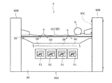
図2に示されているように、抽選装置Aは、転動体としての1個のボールbを用いて抽選ゲームを行うものである。図4によく示されているように、抽選装置Aは、軌道部材としての一対のレール4A,4B(手前側のレール4Aについて図3および図5参照)、レール4Bを操作する操作機構5、レール4A,4Bの下方に設けられた一例として4つの入賞部6、レール4A,4B上にボールbを投入する投入機構7、および入賞部6に入ったボールbを回収する回収機構8を基本的な構成要素として備えている。
As shown in FIG. 2, the lottery apparatus A performs a lottery game using one ball b as a rolling element. 4, the lottery device A includes a pair of
一対のレール4A,4Bは、図3および図4に示されているように正面から見れば、全体的に湾曲凹状を呈している一方、部分的には波状に形成されている。これらのレール4A,4Bは、図5に示されているように、断面がLの字状に形成されており、ボールbの径よりも小さい間隔をあけて互いに平行となるように配置されている。手前側のレール4Aは、抽選装置Aの左右両側に位置する側部筐体90Bに固定されており、後述する入賞部6の穴60が設けられた中央筐体90Aの上部プレート91から所定高さに位置している。一方、奥方側のレール4Bは、その長手方向を回転軸として左右両側の側部筐体90Bに回転可能に支持されており、通常は上記手前側のレール4Aと同一高さに位置している。より具体的には、図4および図5に示されているように、レール4Bの一端部には、連結部材40が固定されており、この連結部材40の先端部が支持ロッド41を介して回転可能に一方の側部筐体90Bに支持されている。支持ロッド41には、コイルバネ42が嵌め合わされており、このコイルバネ42によってレール4Bが常に上方側に回転するように付勢されている。レール4Bは、図示しないストッパなどに当接することで他方のレール4Aと平行する位置で止まるようになっている。また、連結部材40の基端部には、操作機構5を構成する2つのリンクアーム50,51を介してレール開閉用のソレノイド52が連結されている。このような平行状態にあるレール4A,4B上にボールbが投入されると、このボールbは、レール4A,4Bにより形成された軌道に沿って左右に転がりながら往復移動する。このとき、ソレノイド52がマイクロコンピュータによって制御されることでオンになると、図5に仮想線で示すように、連結部材40がリンクアーム50,51の動きに連動して下方側に回転させられ、これにより、奥方側のレール4Bが手前側のレール4Aに対して離間するように斜め下方に退避させられる。その結果、レール4A,4B上において往復移動していたボールbは、これらレール4A,4Bの間をすり抜けるようにして下方に落ちる。
The pair of
再び図4に示されているように、各入賞部6には、レール4A,4Bから落ちてきたボールbが入りうる穴60が設けられている。これらの穴60は、レール4A,4Bに沿って等間隔で並ぶように中央筐体90Aの上部プレート91に開口されている。また、中央筐体90Aの内部には、上部プレート91と重なりつつもスライド用のソレノイド92によって水平にスライドされるスライドプレート93が設けられている。このスライドプレート93には、上部プレート91に開口された穴60と同一の大きさで同一間隔となるように穴94が開口されている。また、上部プレート91とスライドプレート93との間には、穴60に入ったボールbを検知するセンサ95が各穴60と対応するように設けられている。レール4A,4Bからボールbが落下させられる際、スライドプレート93は、各穴94が上部プレート91の各穴60とずれたような位置関係にある。そのため、レール4A,4Bから落ちてきたボールbは、スライドプレート93の上面に支持され、上部プレート91の一つの穴60に半分ほど入った状態で一旦保持される。ボールbが穴60に入って保持された状態になると、当該穴60に対応するセンサ95からマイクロコンピュータにボールbを検知した旨の信号が出力される。その後、スライドプレート93は、各穴94が上部プレート91の各穴60と重なるようにソレノイド92によってスライドさせられ、これにより、ボールbが穴94から落ちて回収機構8に送られる。なお、本実施形態では、レール4A,4Bから落下したボールbが必ずいずれか一つの穴60に入るように構成されているが、他の例としては、入賞部6の穴60とは別箇所にはずれ用の穴を設けておき、このはずれ用の穴に落ちたボールも回収機構8に送られる構成としてもよい。
As shown in FIG. 4 again, each winning
図3に示されているように、中央筐体90Aの前面パネル96には、各入賞部6の穴60にボールbが入った場合のメダルの払い出し枚数(入賞内容に関する情報)を表示するための表示部61が、各入賞部6の位置と対応するように設けられている。これらの表示部61は、本実施形態の例では7セグメントLEDによって構成されており、マイクロコンピュータによって制御されるようになっている。マイクロコンピュータは、抽選ゲームの状況に応じて各表示部61に表示させるメダルの払い出し枚数を変動させることができる。
As shown in FIG. 3, on the
投入機構7は、図4に良く示されているように、片側(右側)の側部筐体90Bの内部に設けられており、この投入機構7は、上下方向に巻掛走行させられる無端ベルト70、無端ベルト70の上部および下部が巻き掛けられるプーリ71A,71B、無端ベルト70に固定されたボール載置用のベース72、および下部側のプーリ71Bを駆動するモータ73を有して構成されている。通常、ベース72は、レール4A,4B上にボールbを投入する位置となる最上位(同図に仮想線で示した位置)よりも若干下方の位置(待機位置)にあり、ボールbを載せた状態で待機している。このとき、ベース72は、下部に設けられたコイルバネ72Aの付勢力により、ボールbがこぼれ落ちないように若干傾斜した姿勢を保っている(同図に実線で示した状態を参照)。抽選ゲームを開始するとき、マイクロコンピュータがモータ73を制御することで無端ベルト70が動作させられ、これにより、ベース72は、ボールbを載せたまま最上位へと移動させられる。ベース72が最上位に達すると、このベース72は、側部筐体90Bの上部に開口された投入口90Cに臨む姿勢となる。このとき、ベース72は、その一部が投入口90C付近に固定されたストッパ90Dに引っ掛かることにより、ベース72の投入口90C側が下方に向けて傾斜する。その結果、ベース72に載せられていたボールbが投入口90Cからレール4A,4Bの方へと転がり落ちてゆき、レール4A,4B上にボールbが投入される。
As shown well in FIG. 4, the
回収機構8は、図4に良く示されているように、シーソー状に傾動可能なガイド部材80によって構成されている。このガイド部材80は、常にその片側(同図では右側)が図示しないバネによって上方に付勢されており、通常時は、その付勢された部位の反対側(同図では左側)が下方に傾斜してボールbを保持可能な姿勢にある。入賞部6の穴60にボールbが入ったことがセンサ95によって検知されると、その旨の信号がマイクロコンピュータに伝えられ、マイクロコンピュータは、投入機構7のモータ73を制御することで無端ベルト70を動作させる。これにより、投入機構7のベース72は、最上位から最下位(同図に実線で示した位置)へと下降移動させられる。このとき、ベース72の一部がガイド部材80の右側先端部に引っ掛かることにより、このガイド部材80の右側が下方に向けて傾斜する(同図に仮想線で示した状態を参照)。その後、マイクロコンピュータは、ソレノイド92を制御することでスライドプレート93をスライドさせる。これにより、入賞部6の穴60に保持されていたボールbは、スライドプレート93の穴94からガイド部材80へと落ち、さらにこのボールbは、ガイド部材80に沿って転がりながらベース72の方へと移動する。ベース72にボールbが載った後、このベース72は、先述した待機位置まで上昇させられる。
The
次に、抽選装置Aの動作について説明する。 Next, the operation of the lottery apparatus A will be described.
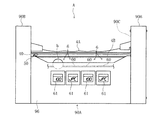
図6〜9は、抽選ゲームの態様を示している。この抽選ゲームは、サブチャッカ32にメダルmが入ることで所定のゲームが実行され、そのゲーム結果として次に進む状態になることにより、抽選装置Aによって実行される。なお、抽選ゲームの実行開始前には、ボールbを投入してからレール4A,4Bが開放するまでの動作時間について、たとえば15秒から30秒の範囲でプレイヤに決定させるための画面が画像表示装置2に表示される。プレイヤが操作スイッチ13Bを用いて上記動作時間を決定すると、この動作時間がカウントダウンされるようすが画像表示装置2に表示されるとともに、抽選ゲームが実際に開始される。本実施形態では、一例として抽選ゲームを最大4回行うようになっている。
6-9 has shown the mode of the lottery game. This lottery game is executed by the lottery device A when a predetermined game is executed when the medal m enters the sub-chucker 32 and the game results in the next state. In addition, before the start of the lottery game, the screen for allowing the player to determine the operation time from the insertion of the ball b to the release of the
図6に示されているように、1回目の抽選ゲームの開始時には、レール4A,4B上にボールbが投入され、ボールbがレール4A,4Bに沿って左右に転がりながら往復移動する。このとき、ボールbは、左右に往復移動するものの、波状のレール4A,4Bに沿って転がるため、このボールbが若干上下に変位しながら往復移動する。これにより、プレイヤは、画像表示装置2上にカウントダウンしながら変動表示される動作時間が0になるまでの間、ボールbの往復移動する動きが面白い動きに見えるとともに、ボールbがどこで落ちるかといった期待感が高められる。なお、1回目の抽選ゲームにおいてボールbが入賞部6の穴60に入るまでの間、全ての入賞部6の表示部61には、たとえば「JPC(ジャックポットチャンス)」といった入賞内容に関する情報が表示されている。
As shown in FIG. 6, at the start of the first lottery game, the ball b is thrown on the
動作時間が0になると、図7に示されているように、奥方側のレール4Bが下方に退避させられる。これにより、レール4A,4B上で往復移動していたボールbがレール4A,4Bの間から落下し、適当な入賞部6の穴60に入ることとなり、1回目の抽選ゲームの結果が得られる。すると、そのボールbが入った入賞部6の表示部61には、例えば「50」といったメダルの払い出し枚数が表示される。その他の入賞部6の表示部61には、「JPC」の表示が継続される。その後、回収機構8によって穴60に入ったボールbが回収されるとともに、そのボールbが投入機構7に送られ、再び上記1回目の抽選ゲームと同様の手順で2回目の抽選ゲームが行われる。
When the operation time reaches 0, the
2回目の抽選ゲームにおいては、図8に示されているように、1回目の抽選ゲームでボールbが入らなかった穴60にボールbが入ると、そのボールbが入った入賞部6の表示部61(1回目の抽選ゲームにおいてボールbが入った入賞部6の表示部61を含む)に例えば「100」といったメダルの払い出し枚数が表示される。その他の入賞部6の表示部61には、「JPC」の表示が継続される。なお、2回目の抽選ゲームにおいて、1回目の抽選ゲームでボールbが入ったのと同じ入賞部6の穴60にボールbが入った場合には、その入賞部6の表示部61に表示されていた枚数である50枚のメダルmがフィギュアロボット14の口14AからメダルゲームフィールドMFに払い出され、次の抽選ゲームに進むことなくゲームが終わる。
In the second lottery game, as shown in FIG. 8, when the ball b enters the
同様に、3回目の抽選ゲームもまた、上記と同様の手順で実行されるが、この3回目の抽選ゲームにおいては、図9に示されているように、1回目と2回目の抽選ゲームでボールbが入らなかった穴60にボールbが入ると、そのボールbが入った入賞部6の表示部61(1回目および2回目の抽選ゲームにおいてボールbが入った入賞部6の表示部61を含む)に例えば「200」といったメダルの払い出し枚数が表示される。一方、1〜3回目までの抽選ゲームにおいて未だボールbが入っていない入賞部6については、この入賞部6の表示部61に例えば最大2000枚ものメダルが払い出されることを示す「SJP(スーパージャックポット)」が表示される。なお、3回目の抽選ゲームにおいて、1回目と2回目の抽選ゲームでボールbが入ったのと同じ入賞部6の穴60にボールbが入った場合には、その入賞部6の表示部61に表示されていた枚数である100枚のメダルmがフィギュアロボット14の口14AからメダルゲームフィールドMFに払い出され、次の最後4回目の抽選ゲームに進むことなくゲームが終わる。最終的に4回目の抽選ゲームを行った結果、「SJP」と表示された入賞部6の穴60にボールbが入ると、その「SJP」に対応する相当枚数(最大2000枚)のメダルmがフィギュアロボット14の口14AからメダルゲームフィールドMFに払い出され、プレイヤにとっては非常に多くのメダルmを獲得できる有利な状況となる。4回目の抽選ゲームにおいて、「SJP」以外の「200」と表示された入賞部6の穴60にボールbが入った場合には、その入賞部6の表示部61に表示されていた枚数である200枚のメダルmがフィギュアロボット14の口14AからメダルゲームフィールドMFに払い出され、抽選ゲームが終わる。
Similarly, the third lottery game is also executed in the same procedure as described above. In the third lottery game, as shown in FIG. 9, the first and second lottery games are performed. When the ball b enters the
したがって、本実施形態の抽選装置Aによれば、ボールbが上下に変位しながら往復移動することで従来とは異なる趣向のボールbの動きが演出されるとともに、ボールbを落下させるプロセスにプレイヤを能動的にかかわらせることができ、これにより、ボールbを用いた抽選ゲームを斬新で面白いものとすることができる。 Therefore, according to the lottery apparatus A of the present embodiment, the ball b moves back and forth while being displaced up and down, and the movement of the ball b having a different taste from the conventional one is produced, and the player is in the process of dropping the ball b. Can be actively involved, so that the lottery game using the ball b can be made novel and interesting.
抽選ゲームの進め方としては、次のようにしてもよい。 The lottery game may be advanced as follows.
図10〜13は、抽選ゲームの他の進め方による態様を示している。たとえば図10に示されているように、抽選ゲームの開始前には、入賞部6の表示部61に例えば「50」といったメダルの払い出し枚数や、「JPC」といった入賞内容に関する情報が表示される。レール4A,4B上にボールbが投入された後、プレイヤが任意のタイミングで操作スイッチ13Bを操作すると、奥方側のレール4Bが下方に退避させられてレール4A,4Bが開放される。これにより、レール4A,4B上で往復移動していたボールbがプレイヤの狙った位置で落下し、適当な入賞部6の穴60に入る。そして、たとえば「50」といったメダルの払い出し枚数が表示されている入賞部6の穴60にボールbが入った場合には、当該枚数のメダルmがフィギュアロボット14の口14AからメダルゲームフィールドMFに払い出され、次のステージに進むことなくゲームが終わる。
10-13 has shown the aspect by the other way of a lottery game. For example, as shown in FIG. 10, before the lottery game is started, the
一方、「JPC」が表示されている入賞部6の穴60にボールbが入った場合には、図11に示されているように、メダルの払い出し枚数がさらに多い次のステージに進む。このステージに進むと、入賞部6の表示部61にそれまで表示されていた数より多い「300」といったメダルの払い出し枚数や、「SJP」といった入賞内容に関する情報が表示され、上記と同様の手順で抽選ゲームが実行される。たとえば「300」といったメダルの払い出し枚数が表示されている入賞部6の穴60にボールbが入った場合には、当該枚数のメダルmがフィギュアロボット14の口14AからメダルゲームフィールドMFに払い出され、抽選ゲームが終わる。「SJP」が表示されている入賞部6の穴60にボールbが入った場合には、相当枚数(最大2000枚)ものメダルmがフィギュアロボット14の口14AからメダルゲームフィールドMFに払い出され、プレイヤにとっては非常に多くのメダルmを獲得できる有利な状況となる。
On the other hand, when the ball b enters the
また、図12および図13に示すものでは、画像表示装置2上で行われる電子ゲームで所定のゲーム結果が得られることにより、抽選装置Aによる抽選ゲームが実行される。図12に示されているように、抽選ゲームの開始時、各入賞部6の表示部61には、たとえば「100」「25」「75」「50」というようにメダルの払い出し枚数がランダムに表示される。レール4A,4B上にボールbが投入された後、プレイヤが任意のタイミングで操作スイッチを操作すると、奥方側のレール4Bが下方に退避させられてレール4A,4Bが開放される。
12 and 13, a lottery game is executed by the lottery device A when a predetermined game result is obtained in an electronic game performed on the
ここで、図13に示されているように、各入賞部6の表示部61においては、ボールbの投入開始から時間が経過するにつれ、表示されていた数が次第に減っていくように表示される。プレイヤは、各表示部61で表示されていた数がすべて「0」になるまでの間にボールbを落下させるための操作を行わなければならない。たとえば、ボールbが入賞部6の穴60に入り、その時点でその入賞部6の表示部61に表示されていた数が「38」であった場合、その表示数と同数の38枚のメダルmがフィギュアロボット14の口14AからメダルゲームフィールドMFに払い出されることとなる。ボールbを落下させるための操作がなされることなく、各入賞部6の表示数が全て「0」になると、自動的にレール4A,4Bが開放させられてボールbが落下させられる。つまり、最終的に「0」となった入賞部6の穴60にボールbが入ったとしても、メダルが払い出されないこととなり、そのため、プレイヤは、ボールbを落とす位置とタイミングを適当に考えながら操作しなければならない。これにより、抽選ゲームとしては、プレイヤにとってより一層興趣のある複雑なものとなる。
Here, as shown in FIG. 13, on the
なお、本願発明は、上記の実施形態に限定されるものではない。 In addition, this invention is not limited to said embodiment.
転動体としては、球状のボールに限らず、たとえば円板状のメダルなどを用いてもよい。円板状のメダルなどを用いる場合、軌道部材としては、たとえば断面凹状の軌道を形成してメダルなどが転がりやすいように一対のレールを近接配置するのが好ましい。 The rolling element is not limited to a spherical ball, and for example, a disk-shaped medal may be used. In the case of using a disk-shaped medal or the like, it is preferable that a pair of rails be arranged close to each other so that the track member has a concave cross-section and the medal or the like is easy to roll.
軌道部材としてのレールは、それ自体の形状によってボールが自ずと往復移動するように構成されているが、たとえばレールを左右上下などに強制的に揺動させることでボールを往復移動させるようにしてもよい。また、上記実施形態では、一方のレールが回転可能に構成されているが、たとえば一方のレールが他方の固定されたレールから水平方向に移動することで離間させられるように構成してもよく、あるいは、両方のレールを水平移動可能とし、これら両方のレールを互いに離間させるように構成してもよい。 The rail as the track member is configured so that the ball naturally reciprocates depending on the shape of the track member. For example, the rail may be reciprocated by forcibly swinging the rail horizontally and vertically. Good. Moreover, in the said embodiment, although one rail is comprised rotatably, you may comprise, for example so that one rail may be spaced apart by moving to the horizontal direction from the other fixed rail, Alternatively, both rails may be horizontally movable, and both the rails may be separated from each other.
抽選ゲームについては、電子ゲームなどの他のゲームの結果に応じて開始するように構成されているが、たとえばチャッカにメダルが入った時点で抽選ゲームを開始させるようにしてもよい。 The lottery game is configured to start according to the result of another game such as an electronic game. However, for example, the lottery game may be started when a medal enters the chucker.
入賞部の表示部に表示されるメダルの払い出し枚数などについては、ボールを投入する前の時点において、いわゆるスロットマシンのようにあたかも回転しているかのように表示させてもよい。この場合、プレイヤが操作スイッチを操作した時点で各表示部の表示内容がランダムに決定し、それと同時にボールが投入されるように構成することができる。 The number of paid-out medals displayed on the display unit of the winning portion may be displayed as if it were rotating like a so-called slot machine at the time before throwing the ball. In this case, the display content of each display unit is determined at random when the player operates the operation switch, and at the same time, the ball can be thrown.
抽選装置としては、メダルゲーム機に限らず、その他各種のゲーム機に装備することができ、さらには、抽選装置単独でゲーム機を構成することもできる。 The lottery device is not limited to the medal game machine, and can be equipped in various other game machines. Furthermore, the lottery device can be configured as a single game machine.
A 抽選装置
b ボール(転動体)
4A,4B レール(軌道部材)
5 操作機構
6 入賞部
60 入賞部の穴
61 表示部(表示手段)
7 投入機構
8 回収機構
95 センサ(検知手段)
A lottery equipment b ball (rolling element)
4A, 4B rail (track member)
5
7
Claims (6)
上記転動体が転がりながら往復移動するための軌道を形成するとともに上縁が全体的に湾曲凹状をして上記転動体を転がり移動可能に支持する一対のレールからなる軌道部材と、
上記一対のレールを相対的に離間させることにより上記軌道部材の任意の長手方向位置から上記転動体を落下させる操作機構と、
上記軌道部材の長手方向に沿って下方に設けられているとともに、上記転動体が入りうる穴をそれぞれ有する複数の入賞部と、
上記各入賞部に設けられており、当該入賞部の穴に入った上記転動体を検知する検知手段と、
上記転動体が上記軌道部材上を往復移動するように上記軌道部材上に上記転動体を投入する投入機構と、
を備えており、
上記操作機構は、上記軌道部材上に上記転動体が投入されてから所定時間経過後に上記一対のレールを相対的に離間させて上記軌道部材から上記転動体を落下させることを特徴とする、抽選装置。 A lottery device for performing a lottery game using a spherical or disk-shaped rolling element,
A track member comprising a pair of rails that form a track for reciprocating while the rolling element rolls, and whose upper edge has a curved concave shape as a whole and supports the rolling element so as to be able to roll and move;
An operation mechanism for dropping the rolling elements from an arbitrary longitudinal position of the track member by relatively separating the pair of rails;
A plurality of winning portions provided below along the longitudinal direction of the raceway member, and each having a hole into which the rolling element can enter,
A detecting means provided in each winning portion, for detecting the rolling element that has entered the hole of the winning portion;
An input mechanism that inputs the rolling element onto the track member so that the rolling element reciprocates on the track member;
Equipped with a,
The operation mechanism is characterized in that the rolling members are dropped from the track members by relatively separating the pair of rails after a predetermined time has elapsed since the rolling members were put on the track members. apparatus.
上記転動体が転がりながら往復移動するための軌道を形成するとともに上縁が全体的に湾曲凹状をして上記転動体を転がり移動可能に支持する一対のレールからなる軌道部材と、
上記一対のレールを相対的に離間させることにより上記軌道部材の任意の長手方向位置から上記転動体を落下させる操作機構と、
上記軌道部材の長手方向に沿って下方に設けられているとともに、上記転動体が入りうる穴をそれぞれ有する複数の入賞部と、
上記各入賞部に設けられており、当該入賞部の穴に入った上記転動体を検知する検知手段と、
上記転動体が上記軌道部材上を往復移動するように上記軌道部材上に上記転動体を投入する投入機構と、
を備えており、
上記操作機構は、プレイヤの入力操作または所定のゲーム結果に応じて上記一対のレールを相対的に離間させて上記軌道部材から上記転動体を落下させることを特徴とする、抽選装置。 A lottery device for performing a lottery game using a spherical or disk-shaped rolling element,
A track member comprising a pair of rails that form a track for reciprocating while the rolling element rolls, and whose upper edge has a curved concave shape as a whole and supports the rolling element so as to be able to roll and move;
An operation mechanism for dropping the rolling elements from an arbitrary longitudinal position of the track member by relatively separating the pair of rails;
A plurality of winning portions provided below along the longitudinal direction of the raceway member, and each having a hole into which the rolling element can enter,
A detecting means provided in each winning portion, for detecting the rolling element that has entered the hole of the winning portion;
An input mechanism that inputs the rolling element onto the track member so that the rolling element reciprocates on the track member;
With
The lottery apparatus , wherein the operation mechanism drops the rolling elements from the track member by relatively separating the pair of rails according to an input operation of a player or a predetermined game result .
Priority Applications (1)
| Application Number | Priority Date | Filing Date | Title |
|---|---|---|---|
| JP2004244850A JP4495548B2 (en) | 2004-08-25 | 2004-08-25 | Lottery equipment |
Applications Claiming Priority (1)
| Application Number | Priority Date | Filing Date | Title |
|---|---|---|---|
| JP2004244850A JP4495548B2 (en) | 2004-08-25 | 2004-08-25 | Lottery equipment |
Publications (2)
| Publication Number | Publication Date |
|---|---|
| JP2006061250A JP2006061250A (en) | 2006-03-09 |
| JP4495548B2 true JP4495548B2 (en) | 2010-07-07 |
Family
ID=36108232
Family Applications (1)
| Application Number | Title | Priority Date | Filing Date |
|---|---|---|---|
| JP2004244850A Expired - Fee Related JP4495548B2 (en) | 2004-08-25 | 2004-08-25 | Lottery equipment |
Country Status (1)
| Country | Link |
|---|---|
| JP (1) | JP4495548B2 (en) |
Families Citing this family (10)
| Publication number | Priority date | Publication date | Assignee | Title |
|---|---|---|---|---|
| JP4835982B2 (en) * | 2006-04-05 | 2011-12-14 | 株式会社セガ | Pusher game device |
| JP4895987B2 (en) * | 2007-12-03 | 2012-03-14 | 株式会社カプコン | game machine |
| JP5424554B2 (en) * | 2007-12-03 | 2014-02-26 | 株式会社カプコン | game machine |
| JP5227574B2 (en) * | 2007-12-03 | 2013-07-03 | 株式会社カプコン | game machine |
| JP4412740B2 (en) * | 2007-12-18 | 2010-02-10 | 株式会社コナミデジタルエンタテインメント | Jackpot lottery apparatus, and game apparatus and game system using the same |
| KR101228123B1 (en) | 2010-10-29 | 2013-02-04 | 신안재 | Education apparatus and method for ecoactivity |
| JP4995333B2 (en) * | 2011-07-07 | 2012-08-08 | 株式会社カプコン | game machine |
| JP4995356B2 (en) * | 2012-01-26 | 2012-08-08 | 株式会社カプコン | game machine |
| JP6447864B2 (en) * | 2014-10-22 | 2019-01-09 | 株式会社セガゲームス | Game device |
| JP7373954B2 (en) * | 2019-09-19 | 2023-11-06 | 株式会社タイトー | game machine |
Citations (5)
| Publication number | Priority date | Publication date | Assignee | Title |
|---|---|---|---|---|
| JPH05300970A (en) * | 1992-04-24 | 1993-11-16 | Sammy Ind Co Ltd | Accessory for pinball game machine |
| JP2002210221A (en) * | 2001-01-22 | 2002-07-30 | Konami Co Ltd | Lottery carrying device and game machine provided with the same |
| JP2002315876A (en) * | 2001-04-23 | 2002-10-29 | Fuji Shoji:Kk | Combination game machine |
| JP2003126396A (en) * | 2001-10-19 | 2003-05-07 | Daiichi Shokai Co Ltd | Game machine |
| JP2004113566A (en) * | 2002-09-27 | 2004-04-15 | Copcom Co Ltd | Token game machine |
-
2004
- 2004-08-25 JP JP2004244850A patent/JP4495548B2/en not_active Expired - Fee Related
Patent Citations (5)
| Publication number | Priority date | Publication date | Assignee | Title |
|---|---|---|---|---|
| JPH05300970A (en) * | 1992-04-24 | 1993-11-16 | Sammy Ind Co Ltd | Accessory for pinball game machine |
| JP2002210221A (en) * | 2001-01-22 | 2002-07-30 | Konami Co Ltd | Lottery carrying device and game machine provided with the same |
| JP2002315876A (en) * | 2001-04-23 | 2002-10-29 | Fuji Shoji:Kk | Combination game machine |
| JP2003126396A (en) * | 2001-10-19 | 2003-05-07 | Daiichi Shokai Co Ltd | Game machine |
| JP2004113566A (en) * | 2002-09-27 | 2004-04-15 | Copcom Co Ltd | Token game machine |
Also Published As
| Publication number | Publication date |
|---|---|
| JP2006061250A (en) | 2006-03-09 |
Similar Documents
| Publication | Publication Date | Title |
|---|---|---|
| US8070167B1 (en) | Vacuum crane pick-up device | |
| JP4495548B2 (en) | Lottery equipment | |
| WO2004003865A1 (en) | Gaming device having a multiple moving object game | |
| JPH0632701B2 (en) | Dice game unit | |
| JP2002210221A (en) | Lottery carrying device and game machine provided with the same | |
| JP4831743B2 (en) | Game machine | |
| US7753771B2 (en) | Games system including slot machines and game control method thereof | |
| JP4772296B2 (en) | game machine | |
| JP5424554B2 (en) | game machine | |
| JP5485556B2 (en) | Lottery equipment | |
| JP2001232051A (en) | Medal game machine | |
| JP4323385B2 (en) | game machine | |
| US7806765B2 (en) | Game system including slot machines and game control method thereof | |
| JPWO2007046191A1 (en) | Game machine | |
| JP5097643B2 (en) | game machine | |
| JP5813348B2 (en) | GAME MEDIUM, AND GAME MACHINE COMPRISING THE GAME MEDIUM | |
| JP5155061B2 (en) | Medal game machine | |
| JP5227574B2 (en) | game machine | |
| JP2005296410A (en) | Game machine | |
| JP4895987B2 (en) | game machine | |
| JP4616157B2 (en) | Game device | |
| JP2003236226A (en) | Game machine, playing method using same game machine | |
| JP4991804B2 (en) | Game device | |
| JP5512777B2 (en) | Medal game machine | |
| JP4995333B2 (en) | game machine |
Legal Events
| Date | Code | Title | Description |
|---|---|---|---|
| A621 | Written request for application examination |
Free format text: JAPANESE INTERMEDIATE CODE: A621 Effective date: 20070731 |
|
| A977 | Report on retrieval |
Free format text: JAPANESE INTERMEDIATE CODE: A971007 Effective date: 20090220 |
|
| A131 | Notification of reasons for refusal |
Free format text: JAPANESE INTERMEDIATE CODE: A131 Effective date: 20090804 |
|
| A521 | Written amendment |
Free format text: JAPANESE INTERMEDIATE CODE: A523 Effective date: 20090930 |
|
| A02 | Decision of refusal |
Free format text: JAPANESE INTERMEDIATE CODE: A02 Effective date: 20091201 |
|
| A521 | Written amendment |
Free format text: JAPANESE INTERMEDIATE CODE: A523 Effective date: 20100226 |
|
| A911 | Transfer of reconsideration by examiner before appeal (zenchi) |
Free format text: JAPANESE INTERMEDIATE CODE: A911 Effective date: 20100309 |
|
| TRDD | Decision of grant or rejection written | ||
| A01 | Written decision to grant a patent or to grant a registration (utility model) |
Free format text: JAPANESE INTERMEDIATE CODE: A01 Effective date: 20100406 |
|
| A01 | Written decision to grant a patent or to grant a registration (utility model) |
Free format text: JAPANESE INTERMEDIATE CODE: A01 |
|
| A61 | First payment of annual fees (during grant procedure) |
Free format text: JAPANESE INTERMEDIATE CODE: A61 Effective date: 20100409 |
|
| R150 | Certificate of patent or registration of utility model |
Ref document number: 4495548 Country of ref document: JP Free format text: JAPANESE INTERMEDIATE CODE: R150 Free format text: JAPANESE INTERMEDIATE CODE: R150 |
|
| FPAY | Renewal fee payment (event date is renewal date of database) |
Free format text: PAYMENT UNTIL: 20130416 Year of fee payment: 3 |
|
| FPAY | Renewal fee payment (event date is renewal date of database) |
Free format text: PAYMENT UNTIL: 20160416 Year of fee payment: 6 |
|
| R250 | Receipt of annual fees |
Free format text: JAPANESE INTERMEDIATE CODE: R250 |
|
| R250 | Receipt of annual fees |
Free format text: JAPANESE INTERMEDIATE CODE: R250 |
|
| LAPS | Cancellation because of no payment of annual fees |