JP4494877B2 - Method for reducing dilution of working fluid in liquid systems - Google Patents
Method for reducing dilution of working fluid in liquid systems Download PDFInfo
- Publication number
- JP4494877B2 JP4494877B2 JP2004181332A JP2004181332A JP4494877B2 JP 4494877 B2 JP4494877 B2 JP 4494877B2 JP 2004181332 A JP2004181332 A JP 2004181332A JP 2004181332 A JP2004181332 A JP 2004181332A JP 4494877 B2 JP4494877 B2 JP 4494877B2
- Authority
- JP
- Japan
- Prior art keywords
- fluid
- sample
- reagent
- gel
- buffer
- Prior art date
- Legal status (The legal status is an assumption and is not a legal conclusion. Google has not performed a legal analysis and makes no representation as to the accuracy of the status listed.)
- Expired - Fee Related
Links
Images

Classifications
-
- G—PHYSICS
- G01—MEASURING; TESTING
- G01N—INVESTIGATING OR ANALYSING MATERIALS BY DETERMINING THEIR CHEMICAL OR PHYSICAL PROPERTIES
- G01N35/00—Automatic analysis not limited to methods or materials provided for in any single one of groups G01N1/00 - G01N33/00; Handling materials therefor
- G01N35/08—Automatic analysis not limited to methods or materials provided for in any single one of groups G01N1/00 - G01N33/00; Handling materials therefor using a stream of discrete samples flowing along a tube system, e.g. flow injection analysis
-
- F—MECHANICAL ENGINEERING; LIGHTING; HEATING; WEAPONS; BLASTING
- F04—POSITIVE - DISPLACEMENT MACHINES FOR LIQUIDS; PUMPS FOR LIQUIDS OR ELASTIC FLUIDS
- F04B—POSITIVE-DISPLACEMENT MACHINES FOR LIQUIDS; PUMPS
- F04B19/00—Machines or pumps having pertinent characteristics not provided for in, or of interest apart from, groups F04B1/00 - F04B17/00
- F04B19/006—Micropumps
-
- G—PHYSICS
- G01—MEASURING; TESTING
- G01N—INVESTIGATING OR ANALYSING MATERIALS BY DETERMINING THEIR CHEMICAL OR PHYSICAL PROPERTIES
- G01N35/00—Automatic analysis not limited to methods or materials provided for in any single one of groups G01N1/00 - G01N33/00; Handling materials therefor
-
- Y—GENERAL TAGGING OF NEW TECHNOLOGICAL DEVELOPMENTS; GENERAL TAGGING OF CROSS-SECTIONAL TECHNOLOGIES SPANNING OVER SEVERAL SECTIONS OF THE IPC; TECHNICAL SUBJECTS COVERED BY FORMER USPC CROSS-REFERENCE ART COLLECTIONS [XRACs] AND DIGESTS
- Y10—TECHNICAL SUBJECTS COVERED BY FORMER USPC
- Y10T—TECHNICAL SUBJECTS COVERED BY FORMER US CLASSIFICATION
- Y10T137/00—Fluid handling
- Y10T137/0318—Processes
-
- Y—GENERAL TAGGING OF NEW TECHNOLOGICAL DEVELOPMENTS; GENERAL TAGGING OF CROSS-SECTIONAL TECHNOLOGIES SPANNING OVER SEVERAL SECTIONS OF THE IPC; TECHNICAL SUBJECTS COVERED BY FORMER USPC CROSS-REFERENCE ART COLLECTIONS [XRACs] AND DIGESTS
- Y10—TECHNICAL SUBJECTS COVERED BY FORMER USPC
- Y10T—TECHNICAL SUBJECTS COVERED BY FORMER US CLASSIFICATION
- Y10T436/00—Chemistry: analytical and immunological testing
- Y10T436/11—Automated chemical analysis
- Y10T436/117497—Automated chemical analysis with a continuously flowing sample or carrier stream
- Y10T436/118339—Automated chemical analysis with a continuously flowing sample or carrier stream with formation of a segmented stream
-
- Y—GENERAL TAGGING OF NEW TECHNOLOGICAL DEVELOPMENTS; GENERAL TAGGING OF CROSS-SECTIONAL TECHNOLOGIES SPANNING OVER SEVERAL SECTIONS OF THE IPC; TECHNICAL SUBJECTS COVERED BY FORMER USPC CROSS-REFERENCE ART COLLECTIONS [XRACs] AND DIGESTS
- Y10—TECHNICAL SUBJECTS COVERED BY FORMER USPC
- Y10T—TECHNICAL SUBJECTS COVERED BY FORMER US CLASSIFICATION
- Y10T436/00—Chemistry: analytical and immunological testing
- Y10T436/11—Automated chemical analysis
- Y10T436/119163—Automated chemical analysis with aspirator of claimed structure
-
- Y—GENERAL TAGGING OF NEW TECHNOLOGICAL DEVELOPMENTS; GENERAL TAGGING OF CROSS-SECTIONAL TECHNOLOGIES SPANNING OVER SEVERAL SECTIONS OF THE IPC; TECHNICAL SUBJECTS COVERED BY FORMER USPC CROSS-REFERENCE ART COLLECTIONS [XRACs] AND DIGESTS
- Y10—TECHNICAL SUBJECTS COVERED BY FORMER USPC
- Y10T—TECHNICAL SUBJECTS COVERED BY FORMER US CLASSIFICATION
- Y10T436/00—Chemistry: analytical and immunological testing
- Y10T436/25—Chemistry: analytical and immunological testing including sample preparation
- Y10T436/2575—Volumetric liquid transfer
Landscapes
- Engineering & Computer Science (AREA)
- Mechanical Engineering (AREA)
- General Engineering & Computer Science (AREA)
- Physics & Mathematics (AREA)
- Health & Medical Sciences (AREA)
- Life Sciences & Earth Sciences (AREA)
- Chemical & Material Sciences (AREA)
- Analytical Chemistry (AREA)
- Biochemistry (AREA)
- General Health & Medical Sciences (AREA)
- General Physics & Mathematics (AREA)
- Immunology (AREA)
- Pathology (AREA)
- Automatic Analysis And Handling Materials Therefor (AREA)
- Sampling And Sample Adjustment (AREA)
Description
本発明は導管(conduit)等のチャンネル内での流体を移送する方法に関する。特に本発明はチャンネル内での流体の移送、及び移送される流体の汚れ及び/又は希釈を減少させる方法並びに装置に関する。 The present invention relates to a method for transferring fluid in a channel, such as a conduit. In particular, the present invention relates to a method and apparatus for reducing fluid transfer within a channel and fouling and / or dilution of the transferred fluid.
例えば、分析器(化学的、生物学的及び免疫学的)及び血液表示システム(例えば、Ortho-Clinical Diagnostics社により製造されるOrthoProVue(登録商標)システム)等の液体を処理するシステムである流体システムは当業界において公知である。また、ミクロ流体システムでの流体処理も米国特許商標庁及びWIPO発行の公報によって良く知られている。別個の流体サンプルを分離するための空気の使用、又は別個のサンプルの固定及び情報の提供のための空気を使用する流体処理システムも、また公知である。
流体処理システムにおいて、水、生理塩水等の作動流体(以下、このように定義する)である一つの流体を使用して、処理される流体に定量ポンプを水圧的に組合せて作動させ、吸引又は分取等の処理される流体をより有利に調節することは一般に知られている。移送される流体が定量ポンプの作動に応じて処理されるように、作動流体は確実に作用する。空気をベースにしたシステム又は一部分空気そして一部分作動流体のシステムは、空気の圧縮性を対象とするので、計量を精密且つ正確に行うことは無理がある。 In a fluid processing system, one fluid which is a working fluid (hereinafter, defined as follows) such as water or physiological saline is used to operate a metering pump in combination with a fluid to be processed, and to perform suction or It is generally known to more advantageously adjust the fluid being processed, such as preparative. The working fluid acts reliably so that the fluid to be transferred is processed in response to the operation of the metering pump. Air-based systems or partially air and partially working fluid systems are targeted for air compressibility, so it is impossible to measure accurately and accurately.
作動流体のみを用いたシステムの欠点は、システム中のこの流体が計量される流体を希釈したり、又は化学的に作用することである。乱流、界面での拡散及び内壁での残部の境界層流体により、これらの流体の混合が生ずることになる。一般に、移送される流体を分離するためにエアーギャップ(air gap)を用いることは知られている。空気による圧縮が、理想的には、精密且つ正確な操作が実質的に低下する程には大きくないように、一般的にエアーギャップのサイズは最小限とされる。エアーギャップ又は気泡は2つの流体の間で物理的分離を呈しながら、残った流体の内部壁を“スクラピング”(scrubbing)する作用を果たすことになる。 The disadvantage of a system using only working fluid is that it dilutes or chemically acts on the fluid in which it is metered . Turbulence, diffusion at the interface, and the remaining boundary layer fluid at the inner wall will cause mixing of these fluids . In general, it is known to use an air gap to separate the fluid being transferred. In general, the size of the air gap is minimized so that the compression by air is ideally not so great that precision and precision operation is substantially reduced . The air gap or bubble will act to “scrub” the inner wall of the remaining fluid while presenting a physical separation between the two fluids.
エアーギャップが存在していても種々の要因によって2つの流体の間の混合を増大させ、このことはエアーギャップの効果を下げそして2つの流体の不満足な混じり合いとなる。このような要因は下記の如くである。
※ 流体が流れる導管の内部面の平滑性(粗さと反対)。というのは、粗さが増すと、より多くの流体を保持するからである。
※ 内腔等の導管の内径の変化。というのは、内径の変化は乱流を誘発するからである。
※ 導管面の湿潤性。
※ 吸引するプローブの端部における作動流体の調節。
※ 作動流体と移送される流体のチャンネル表面との接触角。
※ 移送すべき流体のレオロジー。というのは、高粘度の流体は境界層のサイズを大きくするからである。
Even if an air gap exists, various factors increase the mixing between the two fluids, which reduces the effectiveness of the air gap and results in an unsatisfactory mixing of the two fluids. Such factors are as follows.
* Smoothness of the inner surface of the conduit through which fluid flows (opposite of roughness). This is because as the roughness increases, it retains more fluid.
* Changes in the inner diameter of conduits such as lumens. This is because changes in the inner diameter induce turbulence.
* The wettability of the conduit surface.
* Adjusting the working fluid at the end of the aspirating probe.
The contact angle of the channel surface of the fluid being fed moved and the working fluid ※.
* Rheology of fluid to be transferred. This is because high viscosity fluids increase the size of the boundary layer.
従って、非エアーギャップ又は作動流体と処理される流体との間の唯一のエアーギャップでも、作動流体による汚れの影響が注目される臨床化学診断学、免疫学、血液分別学、免疫血液学、そしてミクロ流体学の分野をも含め不満足である。 Therefore, clinical chemistry diagnostics, immunology, blood fractionation, immunohematology, where non-air gaps or even the only air gap between the working fluid and the fluid to be treated are notable for the effects of contamination by the working fluid, and it is dissatisfaction, including in the field of micro-fluid science.
本発明の目的はすでに上に述べた従来技術の不都合を克服するためのものである。本発明の他の目的は流体の汚れ又は望ましくない希釈がより少なく、好ましくはこのようなことがない流体を処理する方法を提供するものである。本発明の他の目的は、流体の汚れ又は望ましくない希釈がより減少し、好ましくはこのようなことがない流体の移送又は分取等の流体の処理を行うことができるシステムを提供するものである。 The object of the present invention is to overcome the disadvantages of the prior art already described above. It is another object of the present invention to provide a method for treating fluids that are less contaminated or undesirably diluted, and preferably not. Another object of the present invention is to provide a system capable of performing fluid processing, such as fluid transfer or fractionation, which reduces fluid fouling or unwanted dilution more preferably and preferably does not. is there.
本発明の上述の又はさらなる目的は、下記;
所望流体を移送させるための作動流体を準備し;
作動流体と所望流体と混和しない第1緩衝流体の第1セグメントを準備し;
所望流体の第1セグメントを準備し;
作動流体と所望流体とに混和しない第2緩衝流体の第2セグメントを準備し;
移送し、そして更に処理すべき所望流体を準備し、そして
第1及び第2緩衝流体を通して、順に、所望流体に力を及ぼす動力源を、作動流体に適用することにより、チャンネル内の所望流体を移送すること:
を含む、チャンネル内の所望流体を移送する方法を提供する本発明の側面に従って達成される。 The above or further objects of the present invention are :
Prepare the working fluid. Used to transfer the Nozomu Tokoro fluid;
Prepare first segment of the first buffer fluid undesired fluid and mixed sum and the working fluid;
Providing a first segment of the desired fluid ;
Providing a second segment of a second buffer fluid that is immiscible with the working fluid and the desired fluid ;
Transfer to, and to prepare a further processing should do the desired fluid, and
Transporting the desired fluid in the channel through the first and second buffer fluids, in turn, by applying a power source that exerts a force on the desired fluid to the working fluid :
This is accomplished in accordance with an aspect of the present invention that provides a method for transporting a desired fluid in a channel.
本発明の他の側面はチャンネル内の移送される流体の汚れ又は希釈を阻止し又は減少させる方法を提供するもので、下記;
所望流体を移送するための作動流体を準備し;
作動流体と所望流体とに混和しない第1緩衝流体の第1セグメントを準備し;
所望流体の第1セグメントを準備し;
作動流体と所望流体とに混和しない第2緩衝流体の第2セグメントを準備し;そして
移送されそして更に処理される所望流体を準備すること:
を含む。
Another aspect of the present invention provides a method for preventing or reducing fouling or dilution of the transported fluid in the channel ;
Providing a working fluid for transferring the desired fluid ;
Providing a first segment of a first buffer fluid that is immiscible with the working fluid and the desired fluid ;
Providing a first segment of the desired fluid ;
Prepare a second segment of the second buffer fluid immiscible with the working fluid and the desired fluid; and the transported and Rukoto Prepare the desired fluid to be further processed:
including.
更に、本発明の側面は分析される流体を分取する方法を提供するもので、下記;
作動流体を有するプローブを準備し
作動流体と所望流体とに混和しない第1緩衝流体のセグメントを緩衝流体源からプローブに吸出し;
分取される流体のセグメントを吸出し;
この流体のセグメントが分取された後作動流体と所望流体とに混和しない第2緩衝流体のセグメントを緩衝流体源からプローブに吸出し;
分取される選定量の流体を吸出し:そして
分取される選定量の流体を分取すること:
を含み、第1と第2緩衝流体の間に存在する流体のセグメントは分取されない。
Further aspects of the present invention provide a method for fractionating a fluid to be analyzed, which includes :
Providing a probe having a working fluid and sucking a segment of a first buffer fluid that is immiscible with the working fluid and the desired fluid from the buffer fluid source into the probe ;
Sucking out segments of fluid to be dispensed ;
Sucking a segment of a second buffer fluid from the buffer fluid source into the probe that is immiscible with the working fluid and the desired fluid after the segment of fluid has been dispensed ;
Aspirate a selected amount of fluid to be dispensed : and dispense a selected amount of fluid to be dispensed :
The segment of fluid present between the first and second buffer fluids is not sorted.
更にまた本発明の側面は、分析物を含む流体サンプルを分析するための分析器を提供し、下記;
分析すべき分析物を含む流体サンプル源;
分析すべき流体サンプルを受入れるためのサンプル受理エレメント;及び
流体に含まれる分析物を検知するための検出器;
サンプルを移行するためのチャンネルを含む流体処理システム:
を含み、上記流体処理システムは、下記;
チャンネル内の作動流体;
作動流体とサンプルとに混和しない第1緩衝流体の第1セグメント;
サンプルの第1セグメント;
作動流体とサンプルとに混和しない第2緩衝流体の第2セグメント;及び
移行しそして分析すべきサンプル:
を含み、
上記流体は、作動流体、第1緩衝流体、流体サンプルの第1セグメント、第2緩衝流体そして分析されるサンプルの順番でチャンネル内に存在する。
Further aspects of the present invention also provides an analyzer for analyzing the fluid sample containing the analyte, following;
Fluid sample source containing the analyte to be analyzed ;
A sample receiving element for receiving a fluid sample to be analyzed ; and a detector for detecting an analyte contained in the fluid;
Fluid treatment system comprising a channel for migrating sample:
And the fluid treatment system comprises :
Working fluid in the channel;
A first segment of a first buffer fluid that is immiscible with the working fluid and the sample;
The first segment of the sample;
The second segment of the second buffer fluid immiscible with the working fluid and the sample; and migrated and analyzed should do Sample:
Including
The fluid, the working fluid, a first buffer fluid, the first segment of the fluid sample is present in the channel in the second buffer fluid and the sample to be analyzed sequentially.
更には本発明の側面は、血液の免疫化学的テスト用の装置を提供し、下記;
サンプル及び試薬の計量システム;
サンプル中に含まれている赤血球を凝集するためのゲルを有する多数のミクロチューブを含むゲル試験カード;
1つ以上のゲルカードを培養するための培養器;
1つ以上のゲルカードを遠心分離するための遠心分離器;及び
次の1つ又は2つ以上を測定するために、上記試験カードの画像を記録し、そして結果を処理するための画像処理及び記録機:
弱から強の凝集強度(0+,1+,2+,3+,4+);
空(empty)のゲルカード:
細胞集団倍化数(double cell population);
過剰の赤血球;及び測定しない結果:
を含み、
上記サンプル及び試薬の計量システムは、サンプル又は試薬を移送するチャンネルを含む流体処理システムを包み、ここで、流体処理システムは、チャンネル内の作動流体;作動流体とサンプルとに混和しない第1緩衝流体の第1セグメント;サンプル又は試薬の第1セグメント;作動流体とサンプル又は試薬とに混和しない第2緩衝流体の第2セグメント;及び移送及び分析すべきサンプル又は試薬を含み、
そして上記流体は、作動流体;第1緩衝流体;流体サンプル又は試薬の第1セグメント;第2緩衝流体;及び分析されるサンプル又は試薬の順番でチャンネル内に存在している。
Further aspects of the invention provide an apparatus for immunochemical testing of blood, which is described below:
Weighing system of a sample and reagents;
A gel test card comprising a number of microtubes with a gel for agglutinating red blood cells contained in the sample;
An incubator for culturing one or more gel curds;
A centrifuge for centrifuging one or more gel cards; and image processing for recording the image of the test card and processing the results to measure one or more of the following; and Recorder:
Weak to strong cohesive strength (0+, 1+, 2+, 3+, 4+);
Empty gel card:
Cell population doubling number (double cell population);
Excess red blood cells; and unmeasured results:
Including
Weighing system of the sample and reagents, wrapped fluid treatment system comprising a channel for transferring the sample or reagent, wherein the fluid treatment system, the working fluid in the channel; first buffer immiscible with the working fluid and the sample A first segment of fluid; a first segment of sample or reagent; a second segment of a second buffer fluid that is immiscible with the working fluid and the sample or reagent; and a sample or reagent to be transferred and analyzed;
The fluid is then present in the channel in the following order: working fluid; first buffer fluid; first segment of fluid sample or reagent; second buffer fluid; and sample or reagent to be analyzed.
本発明の更なる側面はミクロシステムのプラットホームを含むミクロ流体素子処理システムを提供するもので、このプラットホームは第1の平らな平面及びこの第1の面の反対側に第2の平らな平面を有する基材を含むものである。この第1の面は、少なくとも1つのミクロチャンネル、任意の試薬源、任意の反応室、流体を移送する動力源、ミクロチャンネル内の作動流体、作動流体及び所望流体と混和しない第1緩衝流体の第1セグメント、所望流体の第1セグメント、作動流体及び所望流体と混和しない第2緩衝流体の第2セグメント、及び移行され更に処理される所望流体を有するもので、ここでミクロチャンネル内に存在する流体は、作動流体、第1緩衝流体、所望流体の第1セグメント、第2緩衝流体及び所望流体の順番で存在する。 A further aspect of the present invention provides a microfluidic device processing system including a microsystem platform, the platform having a first flat plane and a second flat plane opposite the first plane. The base material which has is included. This first surface comprises at least one microchannel, an optional reagent source, an optional reaction chamber, a power source for transferring fluid, a working fluid in the microchannel, a working buffer and a first buffer fluid that is immiscible with the desired fluid first segment of, those having a desired first segment of the fluid, the working fluid and the desired fluid and the second segment of the second buffer fluid not mixed sum, and migrated desired fluid to be further processed, wherein the microchannel Are present in the order of working fluid, first buffer fluid, first segment of desired fluid, second buffer fluid and desired fluid.
本発明の更なる目的、構成及び利点は、次に述べる好ましい記載から詳細に考慮することにより当業者において明白であろう。 Further objects, features and advantages of the present invention will become apparent to those skilled in the art from a detailed consideration of the preferred description which follows.
例えば、導管等の壁を有するチャンネルを用いた流体処理システムにおいて、流体の流れる速度の分布は均一ではない。但し中央部が最も速度が速い。2つの間が分離されない場合には、作動流体は常に所望流体(例えば、試薬又はサンプル)と混合する。このことは大部分のおのおのの溶解性に由来する。相当量の所望流体の死容積(dead volume)は作動流体による所望流体の汚れを避けるために吸引吸出することができるけれども、固体壁での流体の速度は0になることによって、常に或る程度の汚れは生ずることになる。一般的な処理は、単一の気泡を用いて所望流体から作動流体を分離する。この技術は2つの異った流体の間での汚れを減少させることに役立つ。しかし、単一の気泡によって汚れを避けるためには、液体−空気の界面のチャンネルを通過する際に、流体はチャンネル面を被っていくという事実による欠点が存在する。本発明者等は第2の気泡を導入することによって、2つの気泡の間に存在する流体は、先の流体の汚れに対する希釈剤として作用することをここに新たに見出した。2つの気泡の間の流体の濃度は作動流体より汚れは明らかに少ない。従って、所望流体の汚れは明らかに減少する。 For example, in a fluid processing system using a channel having a wall such as a conduit, the distribution of the flow velocity of the fluid is not uniform. However, the central part is the fastest. If there is no separation between the two, the working fluid always mixes with the desired fluid (eg, reagent or sample). This comes from the solubility of most of each. A substantial amount of dead volume of the desired fluid can be aspirated and sucked to avoid fouling of the desired fluid by the working fluid, but the fluid velocity at the solid wall will always be some degree by zero Dirt will occur. A typical process uses a single bubble to separate the working fluid from the desired fluid. This technique helps to reduce the fouling between two different fluids. However, in order to avoid contamination by single bubbles, liquids - in passing through the interface of the channel of the air, the fluid is present the disadvantage due to the fact that will cover the channel surface. The inventors have now newly found that by introducing a second bubble, the fluid present between the two bubbles acts as a diluent for the soil of the previous fluid. The fluid concentration between the two bubbles is clearly less fouling than the working fluid. Thus, the contamination of the desired fluid is clearly reduced.
本発明は処理され又は反応された流体の希釈又は汚れを減少させ又は好ましくは阻止することに関し、また本発明は空気等のシステムによるよりも圧縮性が低いので、所望流体を処理(例えば、移送又は分取)するのに容易に調節できるため、このシステムのチャンネル内に存在する流体(作動流体という)によって処理されるもの(所望流体)に用いられる。しかしながら、上に述べたように作動する系の間に空気を用い又は用いなくても、作動流体を用いるシステムには、所望流体の汚れ及び希釈の問題は依然として続いて生ずることになる。 The present invention relates to reducing or preferably preventing dilution or fouling of the treated or reacted fluid, and because the present invention is less compressible than with a system such as air, the desired fluid is treated (eg, transported). It can be easily adjusted to be dispensed), so it is used for what is treated by a fluid (referred to as working fluid) present in the channel of this system (desired fluid). However, the problem of fouling and dilution of the desired fluid will continue to occur in systems using working fluids with or without air between systems operating as described above.
本発明者等は、更に空気のセグメント(又は非反応性の混和しない流体)を用いることにより、作動流体による所望流体の希釈及び/又は汚れは減少され及び/又は阻止することを更に新たに見出した。このことは特にミクロ流体素子の処理において該当する。本発明の好ましい態様として、作動流体を導入した後に、気泡をシステムに吸入することである。所望流体の所定量を吸引し、次いで気泡を吸引する。実際に分取されるべき所望流体を次に吸引する。2つの気泡と計量されるのと同じ物質との層(希釈されていても)は、計量される所望流体を作動流体から分離する。作動流体によって、計量された所望流体の汚れは、それ故に相当の程度で減少している。この態様において、分取すべき流体は、気泡と接触し、この気泡は同一流体の希釈される可能性があるアリコートと接触し、その液体は作動流体から気泡によりやはり分離される。 The inventors have further found that by further using air segments (or non-reactive immiscible fluids), dilution and / or fouling of the desired fluid by the working fluid is reduced and / or prevented. It was. This is particularly true in the processing of microfluidic devices. In a preferred embodiment of the invention, air bubbles are drawn into the system after the working fluid is introduced. A predetermined amount of the desired fluid is aspirated and then the bubbles are aspirated. The desired fluid to be actually dispensed is then aspirated. A layer of the same material as that weighed two bubbles (be diluted) separates the desired fluid to be metered from the working fluid. With the working fluid, the metered desired fluid contamination is therefore reduced to a considerable extent. In this embodiment, the fluid to be fractionated is contacted with air bubbles, the bubbles in contact with aliquots that may be diluted with the same fluid, the liquid is Ru is again separated by air bubbles from the working fluid.
同様に、本発明はまた適当量の分離を得るために必要であるような、所望流体及び緩衝流体(例えば、空気)を更に付加的な分離セグメントとして加える他の態様をも包含する。主たる利点は2つの気泡が2つではなく4つの流体界面を提供し、いずれの流体−空気界面は境界層の表面膜を減少する作用を呈する。このことはシステム中の少量の全空気を容易に調節でき、そして機械的デザインに基づく欠点をも受容してシステムを機能できるようにしている。このことは、本発明を適用することにより、幾何学上及び規模の面から所望流体のデットスペース(dead space)を許さないシステムにおいて、作動流体と所望流体との間の所要の分離を行うことができる。このことはミクロ流体素子においては小さなチャンネルが絶対に必要であるので重要であり、また同伴及び希釈の影響を減少させもする。 Similarly, the present invention also encompasses other embodiments in which the desired fluid and buffer fluid (eg, air) are further added as additional separation segments as necessary to obtain an appropriate amount of separation. The main advantage is that two bubbles provide four fluid interfaces instead of two, and any fluid-air interface acts to reduce the surface film of the boundary layer. This allows a small amount of total air in the system to be easily adjusted and allows the system to function with the disadvantages based on mechanical design. This applies the present invention to provide the required separation between the working fluid and the desired fluid in a system that does not allow dead space of the desired fluid in terms of geometry and scale. Can do. This is important because in microfluidic devices a small channel is absolutely necessary and also reduces the effects of entrainment and dilution.
“所望流体”及び“作動流体”はすでに定義した通りである。この所望流体は、分析等の更に操作を進めるための流体をも包含する。例えば、分析物の存在を分析する、血液又は他の体液もが、所望流体に包含される。ここで分析物とはサンプル中の検出されるもの及び/又は定量される1種以上の分子である。好ましい分析物には、核酸、抗体、蛋白質、糖類等の生物分子が含まれる。ここで用いる血液とは、すべての血液又は赤血球、血漿、漿液等の血液の成分が含まれる。 “Desired fluid” and “working fluid” are as defined above. This desired fluid also includes a fluid for further operation such as analysis. For example, to analyze the presence of the analyte, also blood or other body fluids, are encompassed by the desired fluid. Here, the analyte is one or more molecules to be detected and / or quantified in a sample. Preferred analytes, nucleic acids, antibodies, proteins, include organisms molecules such as sugars,. The blood used herein, all blood or red blood cells, plasma, in which the component is included in the blood of the serum or the like.
作動流体は分析器又はミクロ流体素子処理システム等の装置のチャンネルに送入される。この作動流体は、各使用に応じその都度取換えたり又はより恒久的であって定期的に又は決して換えることのない流体である。この作動流体には、塩水、水、シリコーン油等の不活性油、ヘプタン等の流体が含まれる。 The working fluid is fed into a channel of a device such as an analyzer or microfluidic device processing system. This working fluid is a fluid that is replaced with each use, or is more permanent and does not change regularly or never. The working fluid includes brine, water, inert oils such as silicone oil, the flow of heptane and the like.
本願においていうチャンネルとは、特定の方向に流体を流す通路についてである。このチャンネルは底辺及び側面を有したみぞ又は深いみぞ又は全体が密封された管又は導管等に形成されている。このチャンネルの実際の断面をみると、例えば円形、四角形、矩形、三角形、V形、U形、六角形、八角形、不規則形等である。チャンネルは便利な配置にすれば良く、限定するものではないが、直線、曲線、ぬりくねる(例えば、直線部分が曲線又はループと結合して更に他の直線部分と結合し、また曲線又はループと結合した後第三の直線部分と結合する)である。チャンネルは別個の管と接合するように、例えば直径に段階的に変化がある等の突然に変化があっても良い。例えば、プラスチックのチューブを金属管の外径に接合すると、プラスチックチューブの大きな直径から金属管の小さな直径に突然の移行がある。ミクロチャンネルの用語は、本願のミクロ流動素子の態様では約100μm又はそれ以下の寸法を有するチャンネルについて用いる。 The channel in the present application refers to a passage that allows fluid to flow in a specific direction. This channel is formed in the bottom and sides of a grooves or deep grooves or entirely sealed tube or conduit or the like. The actual cross section of the channel is, for example, a circle, a rectangle, a rectangle, a triangle, a V shape, a U shape, a hexagon, an octagon, an irregular shape, or the like. Channels can be conveniently arranged, but are not limited to straight lines, curves, and windings (eg, a straight line portion is combined with a curve or loop and further connected with another straight portion, and a curve or loop After joining, it is joined with the third straight line portion). As the channel joined to the separate tube, for example, there may be a sudden change such as a stepwise there is a change in diameter. For example, when a plastic tube is joined to the outer diameter of a metal tube, there is a sudden transition from a large diameter of the plastic tube to a small diameter of the metal tube. The term microchannel is used for channels having dimensions of about 100 μm or less in the present microfluidic device embodiment.
第1及び第2の緩衝流体が、作動流体と所望流体との間に存在する。第1緩衝流体は作動流体と所望流体の第1セグメントの間に設けられる。所望流体の第1セグメントと所望流体の他のセグメントとの間に第2緩衝流体が設けられる。第1と第2緩衝流体は同じものでも又は異なったものでも良い。緩衝流体としての要件は所望流体及び作動流体と混和しないことである。本願において用いられる“混和しない”という用語は、2つの別個の流体の間で実質的に混合しないということである。従って、適用された条件下で2つの流体が別々の流体層を維持していたときには、第1流体は第2流体中では混和しないということである。本発明の好ましい態様として、緩衝流体は空気等の気体であるか、又は窒素、アルゴン、二酸化炭素、ヘリウム等の標準的な条件下で比較的に不活性なガスであり、好ましい態様としてすべての緩衝流体は同じものであって、空気である。使用することができる他の緩衝流体はシリコーン油及び/又はヘプタン及び上に述べた等のものが含まれ、或る種の態様として2つ以上の緩衝液体のセグメントを使用してもよい。他の例として、第3、第4等の緩衝流体/複数の所望流体のセグメントを使用してもよい。 First and second buffer fluids are present between the working fluid and the desired fluid. The first buffer fluid is provided between the working fluid and the first segment of the desired fluid. A second buffer fluid is provided between the first segment of the desired fluid and the other segment of the desired fluid. The first and second buffer fluids may be the same or different. The requirement as a buffer fluid is that it is immiscible with the desired fluid and working fluid. The term "immiscible" as used herein is that there is no substantial mixing combined between the two separate fluid. Thus, when the two fluids maintain separate fluid layers under the applied conditions, the first fluid is immiscible in the second fluid. In a preferred embodiment of the present invention, the buffer fluid gas Der such as air Luca, or nitrogen, argon, carbon dioxide, a relatively inert gas at standard conditions, such as helium, all preferred embodiments These buffer fluids are the same and are air. Other buffer fluid that can be used include those such as mentioned silicone oil and / or heptane and above may be used segments of two or more buffering liquid as certain aspects. As another example, third, fourth, etc. buffer fluid / several desired fluid segments may be used.
チャンネルを通して流体を移行させるために動力源が用意される。動力源は適当なデバイスによって準備することができる。例えば、臨床用分析器又は血液型システム等のシステム用として、一般的なポンプシステム又は吸引分取プローブ等が使用できる。 A power source is provided to move fluid through the channel. The power source can be prepared by a suitable device. For example, a general pump system or a suction sorting probe can be used for a system such as a clinical analyzer or a blood group system.
ミクロ流体素子システムでは、少量の流体が移送される。このような場合、動力源はWO 97/21090に記載されているような求心力ポンプによって供給され、またはUSP.5,992,820に記載されているような電極をベースにしたポンプによるものである(両文献の全体を参照し、本明細書に組み入れる)。 In microfluidic device systems, a small amount of fluid is transferred. In such a case, the power source is supplied by a centripetal pump as described in WO 97/21090 or USP. Ru Der by pumps based electrode as described in 5,992,820 (with reference to the whole of both documents are incorporated herein).
処理され又は移送される所望流体は、分析されるテスト素子に分取されるような操作で、又はMTS ID−Micro Typing System(登録商標)のゲルカード等の血液型カードを用いて使用される。このようなカードは、サンプル中に存在する赤血球を凝集するゲルを含んだミクロチューブを有している。USP.5,650,068及び5,552,064(両文献の全体を参照し、本明細書に組み入れる)にも、更にこれに関連した記述が存在する。本願において用いられる“テスト素子”は、USP.3,992,158に記載されているような乾燥スライドテスト素子のような少なくとも1つの試薬を供給する反応容器があり、又はUSP 5,441,895に記載されているような一種以上の抗体を事前に被覆した、若しくは被覆しないキャビティを有する溜め若しくはカップである。好ましい態様として、このシステムは臨床分析器であって、所望流体がテスト素子に分取された後、テスト素子は更に培養され、付加的な試験を行い、そして分光光度計を用いてテスト素子を読み取ることができる。本発明において特に好ましい使用は、すでに述べたMTS ProVue(登録商標)等の免疫血液学のテスト用の自動装置を用いる。
好ましい装置は、下記;
本発明の流体処理システムと、MTS ID−Micro Typingシステム(登録商標)等の1つ以上のゲル試験カードとを含む、サンプルと試薬の計量システム;培養器;遠心分離機;及び画像処理及び記録機、を含む装置であり、
該培養器は1つ以上のゲルカードを培養するものであり、
該遠心分離機は1つ以上の培養されたゲルカードを遠心分離するものであり、
また画像処理及び記録機は遠心分離されたゲルカードの画像を記録し、そしてその結果を処理して、
弱から強の凝集強度(0+,1+,2+,3+,4+);
空のゲルカード:
細胞集団倍化数;
過剰の赤血球;及び測定しない結果:の1つ又は2つ以上を測定するもの、
を含む。
イメージ記録機及びプロセッサーは当業者において良く知られているもので、典型的にはカードのイメージを記録するカメラ、イメージを保存する記録装置そしてイメージを分析するマイクロプロセッサーである。
The desired fluid to be processed or transferred is used in an operation such as being dispensed to the test element to be analyzed, or using a blood group card such as a gel card of MTS ID-Micro Typing System®. . Such a card has a microtube containing a gel that agglutinates red blood cells present in the sample. USP. 5,650,068 and 5,552,064 (see both documents in their entirety and incorporated herein) also have a related description. The “test element” used in this application is USP. There is a reaction vessel that supplies at least one reagent such as a dry slide test element as described in US Pat. No. 3,992,158, or one or more antibodies as described in US Pat. No. 5,441,895. A reservoir or cup having a cavity that is pre-coated or uncoated. In a preferred embodiment, the system is a clinical analyzer, after the desired fluid has been dispensed into the test element, the test element is further incubated, subjected to additional testing, and the spectrophotometer is used to place the test element. Can be read. A particularly preferred use in the present invention uses an automated device for immunohematology testing, such as the MTS ProVue® already mentioned.
Preferred devices are:
Sample and reagent metering system including fluid processing system of the present invention and one or more gel test cards such as MTS ID-Micro Typing System®; incubator; centrifuge; and image processing and recording A machine including a machine,
The incubator is for culturing one or more gel curds,
The centrifuge centrifuges one or more cultured gel cards,
The image processor and recorder also records the centrifuged gel card image and processes the result,
Weak to strong cohesive strength (0+, 1+, 2+, 3+, 4+);
Empty gel card:
Cell population doubling number;
Excess red blood cells; and unmeasured results: measuring one or more of
including.
Image recorders and processors are well known to those skilled in the art and are typically a camera that records an image of a card, a recording device that stores the image, and a microprocessor that analyzes the image.
本発明は特にミクロ流体素子又は流体の微量操作に有用である。このようなシステムはすでに述べたWO 97/21090等の刊行物に記載されている。ミクロ流体素子システムにおいて、好ましいミクロチャンネルには、限定するものではないが、チューブ、みぞ、反対側がバリヤーで形成されたチャンネル等が含まれる。 The present invention is particularly useful for microfluidic devices or fluid micromanipulation. Such systems are described in publications such as WO 97/21090 already mentioned. In microfluidic systems, the preferred micro-channels, but are not limited to, tubes, grooves, opposite side includes a channel or the like formed by the barrier.
好ましいミクロ流体素子のデバイスにおいて、チャンネルは基材の面に形成されたみぞであり、そしてこのデバイスはチャンネルをその上に存在させそしてシールするカバー素子を含んでいる。この態様の応用として、このカバー素子は取り除けるように基材に付随している。 In a preferred microfluidic device, the channel is a groove formed in the surface of the substrate , and the device includes a cover element that causes the channel to reside and seal thereon. As an application of this embodiment, the cover element is associated with the substrate so that it can be removed.
特に好ましいチャンネル/カバーの素子/構成物質には、限定するものではないが、ガラス、珪素、石英、又は他の無機質、プラスチック、セラミックス、金属、紙、メタロイド、半導体物質、セメント等が含まれる。更に、蛋白質(例えば、ゼラチン)等のゲル、リポ多糖類、アガローズ及びポリアクリルアミドを使用できる。広範囲の有機及び無機の重合体であって、天然及び合成のいずれかのものをチャンネル物質として用いることができる。実例的な重合体には、ポリエチレン、ポリプロピレン、ポリ(4−メチルブテン)、ポリスチレン、ポリメタクリレート、ポリエチレンテレフタレート、レイヨン、ナイロン、ポリビニルブチレート、二弗化ポリビニリデン(PVDF)、ポリジメチルシロキサン(PDMS)、シリコーン、ポリホルムアルデヒド、セルロース、酢酸セルロース、ニトロセルロース等が含まれる。 Particularly preferred channel / cover element / constituents, but are not limited to, glass, silicon, quartz, or other minerals, plastic, ceramic, metal, paper, metalloids, semiconductive materials, cements or the like. Furthermore, proteins such as gelatin or the like of the gel, lipopolysaccharide, the agarose and polyacrylamides can be used. A polymer of a wide variety of organic and inorganic, can be used if Re not have a natural and synthetic as a channel material. Illustratively polymers, polyethylene, polypropylene, poly (4-methylbutene), polystyrene, polymethacrylate, polyethylene terephthalate, rayon, nylon, polyvinyl butyrate, difluoride polyvinylidene (PVDF), polydimethylsiloxane (PDMS) , Silicone, polyformaldehyde, cellulose, cellulose acetate, nitrocellulose and the like.
重合体チャンネル物質は、使用目的に応じて硬質、半硬質又は非硬質、不透明、半透明又は透明であることができる。例えば、すべて光学的に又は目視的に検出できる素子は、少なくとも一部分は透明な物質によって検出できるように、一般的には作られる。また、例えばガラス又は石英からの透明な窓をデバイスに組み入れることもできる。更には、重合体物質は、骨格が線状又は枝分れしても良く、また架橋結合又は非架橋結合していても良い。特に好ましい重合体物質の例は、例えばポリジメチルシロキサン(PDMS)、ポリウレタン、ポリ塩化ビニル(VPC)、ポリスチレン、ポリスルホン、ポリカーボネート等が含まれる。すでに述べたように、本願の態様におけるチャンネルはミクロ流体素子のデバイスの構成材料からのものである。本発明のミクロ流体素子の側面において使用されチャンネルの製造法は、当業者において良く知られている。例えば、チャンネルが表面に形成される場合、機械的、金型、彫刻、食刻、積層、押出又は析出等の一般的な技術を用いて形成することができる。このような方法は、より詳細にはWO 02/18949に記載されている。 The polymer channel material can be rigid, semi-rigid or non-rigid, opaque, translucent or transparent depending on the intended use. For example, all optically or visually detectable elements are typically made so that at least a portion can be detected by a transparent material. A transparent window, for example from glass or quartz, can also be incorporated into the device. Furthermore, the polymeric material may be linear or branched in skeleton, and may be cross-linked or non-cross-linked. Examples of particularly preferred polymeric materials include, for example, polydimethylsiloxane (PDMS), polyurethane, polyvinyl chloride (VPC), polystyrene, polysulfone, polycarbonate and the like. As already mentioned, the channels in the present embodiment are from the constituent materials of the microfluidic device. Methods of manufacturing channels used in aspects of the microfluidic device of the present invention are well known to those skilled in the art. For example, when the channel is formed on the surface, it can be formed using a general technique such as mechanical, mold, engraving, etching, lamination, extrusion, or precipitation. Such a method is described in more detail in WO 02/18949.
緩衝流体は公知の方法によってシステムに送入することができる。例えば臨床上の分析器において、一般的には空気である緩衝流体は周辺の空気から計量プローブを通してシステムに吸引される。ミクロ流体素子の態様においては、すでに示したUSP 5,992,820に記載されているように、電極で誘発された気泡が使用される。 The buffer fluid can be delivered to the system by known methods. For example, in a clinical analyzer, buffer fluid, typically air, is aspirated into the system from ambient air through a metering probe. In the microfluidic device embodiment, electrode-induced bubbles are used, as described in USP 5,992,820 already shown.
或る種のシステムにおいて、いずれの所望流体セグメント及び/又は作動流体セグメントとの間にシリコーン油等の緩衝流体を追加的に加えることも可能である。2つの所望流体セグメントの間に2つの緩衝流体を用いる場合は、USP 3,479,141に記載されているような空気及びシリコーン油である。ここでは、空気が緩衝流体であることによって、システムがいわゆる軟化(softening)されることを阻止する利点がある。しかしながら、希釈が進む傾向になるので、いずれの所望流体のセグメント及び/又は作動流体のセグメントの間では、ただ単独の緩衝流体(好ましくは空気)を用いるのが一般的に好ましい。 In certain systems, it is also possible to add buffer fluid such as silicone oil additionally between the desired fluid segments and / or working fluid segments Re not have. When two buffer fluids are used between two desired fluid segments, air and silicone oil as described in USP 3,479,141. Here, there is an advantage of preventing the system from being so-called softening by the fact that the air is a buffer fluid. However, since the tendency for dilution progresses, in between segments of a segmented and / or working fluid have not Re desired fluid, only a single buffer fluid (preferably air) to use is generally preferred.
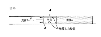
図1aは、作動流体(2)と所望流体(1)との間に緩衝流体が存在していないシステムを示す。この場合、作動流体と所望流体が混和するときには、チャンネルの相当の長さにわたって所望流体がかなり希釈される。図1bは単独の気泡(3)が存在しここでチャンネル側壁の境界層(4)に作動流体が保持されることを示している。この場合、気泡(3)の中に残余の作動流体が存在するので、所望流体(1)が相当程度に希釈される。 FIG. 1a shows a system in which no buffer fluid is present between the working fluid (2) and the desired fluid (1). In this case, when the working fluid and the desired fluid are mixed, the desired fluid is significantly diluted over a substantial length of the channel. FIG. 1b shows that there is a single bubble (3) where the working fluid is retained in the boundary layer (4) of the channel sidewall. In this case, since the remaining working fluid is present in the bubbles (3), the desired fluid (1) is diluted to a considerable extent.
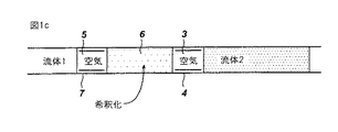
図1cは本発明の態様を示すものである。この実施態様において、第1の気泡(3)が導入され、次いで所望流体の第1セグメント(6)が導入される。所望流体の第1セグメントの後に別の気泡(5)を導入し、次いで所望流体(1)を導入する。第1の気泡(3)は、所望流体(6)のセグメントを相当に希釈しながら、図1bにおける境界層(4)にあって保持された等の作動流体を含んでいる。しかしながら、第2の気泡(5)の存在は、第1の気泡(3)における境界層よりも作動流体によって明らかに希釈が少なくなって所望流体の境界層(7)となる。この結果、更に分取され又は処理された所望流体(1)は、明らかに作動流体による希釈が少なくなっている。 FIG. 1c illustrates an embodiment of the present invention. In this embodiment, the first bubble (3) is introduced and then the first segment (6) of the desired fluid is introduced. Another bubble (5) is introduced after the first segment of the desired fluid and then the desired fluid (1) is introduced. The first bubble (3) contains working fluid, such as retained in the boundary layer (4) in FIG. 1b, while diluting a segment of the desired fluid (6) considerably. However, the presence of the second bubble (5) is clearly less diluted by the working fluid than the boundary layer in the first bubble (3) and becomes the boundary layer (7) of the desired fluid. As a result, the desired fluid (1) which has been further dispensed or processed is clearly less diluted by the working fluid.
本発明の他の側面は、分析するサンプル及び/又は本願方法で使用する試薬を吸引したり分取したりする分析器を提供するものである。この分析器はサンプル溜め、任意には試薬溜め、サンプル及び/又は試薬を移送しそして、分取することのできる流体処理システム、任意には培養器及び分光光度計等の検出器を包含している。流体処理システムは好ましくは、使い捨て吸い口(tip)を含んだ吸引/分取プローブである。サンプル、試薬、及び好ましくは空気である緩衝流体はプローブの吸い口を通して流体処理システムに導入される。免疫測定分析器のシステム等の代表的分析器は、USP 6,096,561及び2000年1月13日に出願した発明の名称「自動臨床分析器における検出法」に開示されている。 Another aspect of the present invention provides an analyzer that aspirates and dispenses a sample to be analyzed and / or a reagent used in the method of the present application. The analyzer includes a sample reservoir, optionally a reagent reservoir, a fluid processing system capable of transferring and dispensing the sample and / or reagent, optionally a detector such as an incubator and a spectrophotometer. Yes. The fluid treatment system is preferably a suction / sorting probe including a disposable tip. Sample, reagent, and buffer fluid, preferably air, are introduced into the fluid handling system through the probe's mouth. Representative analyzers, such as immunoassay analyzer systems, are disclosed in USP 6,096,561 and in the title of the invention filed Jan. 13, 2000 "Detection Methods in Automatic Clinical Analyzers".
本発明における化合物、組成物及び取扱いについては、当業者において種々の改良及び変更することが容易であろう。従って、本願のクレーム及びこれらの均等の範囲内において、改良及び変更するごときは本願発明の範囲に含まれるものである。 It will be easy for those skilled in the art to make various modifications and changes to the compounds, compositions and handling in the present invention. Therefore, improvements and modifications within the scope of the claims of the present application and their equivalents are included in the scope of the present invention.
1 所望流体1
2 作動流体2
3 気泡
4 境界層
5 気泡
6 希釈された所望流体
7 境界層
1 Desired fluid 1
2 Working fluid 2
3 bubbles 4
Claims (7)
該ゲル試験カードはサンプル中に含まれる赤血球を凝集するためのゲルを有する複数のミクロチューブを含むゲルカードであり、該培養器は1つ以上のゲルカードを培養するものであり、該遠心分離機は1つ以上の培養されたゲルカードを遠心分離するものであり、また画像処理及び記録機は遠心分離されたゲルカードの画像を記録し、そしてその結果を処理して、凝集強度(0+,1+,2+,3+,4+)、空のゲルカード、細胞集団倍化数、過剰の赤血球、及び測定しない結果の内の1つ又は2つ以上を測定するものであり、
前記サンプル及び試薬の計量システムは、サンプル又は試薬を移送するチャンネルを含む流体処理システムを含み、ここで、流体処理システムは、
チャンネル内の作動流体;
作動流体とサンプルとに混和しない第1緩衝流体の第1セグメント;
サンプル又は試薬の第1セグメント;
作動流体とサンプル又は試薬とに混和しない第2緩衝流体の第2セグメント;
及び移送及び分析すべきサンプル又は試薬を含み、
そして前記流体は、
作動流体;
第1緩衝流体;
流体サンプル又は試薬の第1セグメント;
第2緩衝流体;
及び分析されるサンプル又は試薬
の順番でチャンネル内に存在しており、
サンプル又は試薬の前記第1セグメントは分取せず、前記分析されるサンプル又は試薬を前記ゲル試験カードに分取することを特徴とする方法。」 A blood immunity test method using a measuring system, a gel test card, an incubator, a centrifuge, and an apparatus including an image processor and a recorder,
The gel test card is a gel card including a plurality of microtubes having a gel for agglutinating erythrocytes contained in a sample, and the incubator is for culturing one or more gel cards, and the centrifugation The machine is one that centrifuges one or more cultured gel cards, and the image processing and recording machine records an image of the centrifuged gel card and processes the result to obtain a cohesive strength (0+ , 1+, 2+, 3+, 4+), empty gel card, cell population doubling number, excess red blood cells, and one or more of unmeasured results,
The sample and reagent metering system includes a fluid processing system including a channel for transporting the sample or reagent, wherein the fluid processing system comprises:
Working fluid in the channel;
A first segment of a first buffer fluid that is immiscible with the working fluid and the sample;
A first segment of sample or reagent;
A second segment of a second buffer fluid that is immiscible with the working fluid and the sample or reagent;
And the sample or reagent to be transferred and analyzed,
And the fluid is
Working fluid;
A first buffer fluid;
A first segment of a fluid sample or reagent;
A second buffer fluid;
And in the order of the sample or reagent to be analyzed,
The method, wherein the first segment of sample or reagent is not dispensed and the sample or reagent to be analyzed is dispensed to the gel test card . "
Applications Claiming Priority (1)
| Application Number | Priority Date | Filing Date | Title |
|---|---|---|---|
| US10/464,156 US7247487B2 (en) | 2003-06-18 | 2003-06-18 | Reducing working fluid dilution in liquid systems |
Publications (3)
| Publication Number | Publication Date |
|---|---|
| JP2005010165A JP2005010165A (en) | 2005-01-13 |
| JP2005010165A5 JP2005010165A5 (en) | 2009-12-03 |
| JP4494877B2 true JP4494877B2 (en) | 2010-06-30 |
Family
ID=33418150
Family Applications (1)
| Application Number | Title | Priority Date | Filing Date |
|---|---|---|---|
| JP2004181332A Expired - Fee Related JP4494877B2 (en) | 2003-06-18 | 2004-06-18 | Method for reducing dilution of working fluid in liquid systems |
Country Status (6)
| Country | Link |
|---|---|
| US (1) | US7247487B2 (en) |
| EP (1) | EP1489303B1 (en) |
| JP (1) | JP4494877B2 (en) |
| KR (1) | KR101140439B1 (en) |
| AU (1) | AU2004202662B2 (en) |
| CA (1) | CA2471686C (en) |
Families Citing this family (28)
| Publication number | Priority date | Publication date | Assignee | Title |
|---|---|---|---|---|
| US6524456B1 (en) * | 1999-08-12 | 2003-02-25 | Ut-Battelle, Llc | Microfluidic devices for the controlled manipulation of small volumes |
| AU2003238401A1 (en) * | 2002-05-24 | 2003-12-12 | Fraunhofer-Gesellschaft Zur Forderung Der Angewandten Forschung E.V. | Method for transferring heterogeneous liquids in microchannels without the occurrence of mixing |
| WO2005072858A1 (en) | 2004-01-26 | 2005-08-11 | President And Fellows Of Harvard College | Fluid delivery system and method |
| EP1672674A1 (en) * | 2004-12-17 | 2006-06-21 | Max-Planck-Gesellschaft zur Förderung der Wissenschaften e.V. | Method and system for high-throughput mass-analysis |
| AU2006236410B2 (en) * | 2005-04-19 | 2012-11-01 | President And Fellows Of Harvard College | Fluidic structures including meandering and wide channels |
| US20060280029A1 (en) * | 2005-06-13 | 2006-12-14 | President And Fellows Of Harvard College | Microfluidic mixer |
| EP2660482B1 (en) * | 2005-08-22 | 2019-08-07 | Life Technologies Corporation | Vorrichtung, System und Verfahren unter Verwendung von nichtmischbaren Flüssigkeiten mit unterschiedlichen Volumen |
| JP4915690B2 (en) * | 2006-05-23 | 2012-04-11 | 国立大学法人電気通信大学 | Micro chemical chip equipment |
| JP4968896B2 (en) * | 2006-09-27 | 2012-07-04 | 富士フイルム株式会社 | Dispersion manufacturing apparatus and dispersion manufacturing method |
| US20100304498A1 (en) * | 2006-10-18 | 2010-12-02 | Konica Minolta Medical & Graphic, Inc. | Microchip reaction detection system and method of reaction of microchip in flow path |
| US7803101B2 (en) * | 2007-01-30 | 2010-09-28 | Ortho-Clinical Diagnostics, Inc. | Random access multi-disc centrifuge |
| US7850917B2 (en) * | 2008-03-11 | 2010-12-14 | Ortho-Clinical Diagnostics, Inc. | Particle agglutination in a tip |
| FR2933315B1 (en) * | 2008-07-07 | 2012-02-10 | Commissariat Energie Atomique | MICROFLUIDIC DEVICE FOR DISPLACING LIQUID |
| FR2934361B1 (en) * | 2008-07-22 | 2012-12-28 | Commissariat Energie Atomique | DEVICE FOR VARYING THE PRESSURE OF A PNEUMATIC FLUID BY DISPLACING LIQUID DROPS AND HEAT PUMP USING SUCH A DEVICE |
| JP4919119B2 (en) * | 2010-01-19 | 2012-04-18 | 株式会社日立プラントテクノロジー | Separation / dispensing method with reagent dispensing nozzle and reagent dispensing / dispensing mechanism |
| US8365616B1 (en) | 2010-09-16 | 2013-02-05 | Wolcott Duane K | Sampling probe for solutions containing soluble solids or high concentrations of dissolved solids |
| US10029041B2 (en) | 2011-11-30 | 2018-07-24 | Pdl Biopharma, Inc. | Filtration module |
| EP2623202B1 (en) * | 2012-01-31 | 2018-07-18 | Siemens Healthcare Diagnostics Products GmbH | Method for heating a volume of liquid in a heated pipetting needle, pipetting device and automated analytical device |
| US9213043B2 (en) | 2012-05-15 | 2015-12-15 | Wellstat Diagnostics, Llc | Clinical diagnostic system including instrument and cartridge |
| US9625465B2 (en) | 2012-05-15 | 2017-04-18 | Defined Diagnostics, Llc | Clinical diagnostic systems |
| US9081001B2 (en) | 2012-05-15 | 2015-07-14 | Wellstat Diagnostics, Llc | Diagnostic systems and instruments |
| US9588027B2 (en) | 2013-03-13 | 2017-03-07 | UPKO Diagnostics, LLC | Mixing of fluids in fluidic systems |
| CN110702640B (en) * | 2014-03-31 | 2022-11-18 | 红移生物分析有限责任公司 | Method of measuring properties of a fluid and method of adjusting a fluid analyzer to operate |
| MX2017007576A (en) | 2014-12-12 | 2018-03-09 | Opko Diagnostics Llc | Fluidic systems comprising an incubation channel, including fluidic systems formed by molding. |
| EP3256255B1 (en) * | 2015-02-13 | 2022-11-09 | Siemens Healthcare Diagnostics Inc. | Methods and apparatus providing reduced carryover during pipetting operations |
| KR101779087B1 (en) * | 2016-03-10 | 2017-09-18 | 조선대학교산학협력단 | Apparatus and method for measuring of blood biophysical property based POCT |
| RU2762936C2 (en) | 2016-10-28 | 2021-12-24 | Бекман Каултер, Инк. | System for assessing substance preparation |
| US20230029423A1 (en) * | 2021-07-15 | 2023-01-26 | Techcyte, Inc. | Remote image analysis for visually assessing agglutination of fluid samples |
Family Cites Families (28)
| Publication number | Priority date | Publication date | Assignee | Title |
|---|---|---|---|---|
| US482599A (en) * | 1892-09-13 | Traction-engine | ||
| US2797149A (en) | 1953-01-08 | 1957-06-25 | Technicon International Ltd | Methods of and apparatus for analyzing liquids containing crystalloid and non-crystalloid constituents |
| US2879141A (en) | 1955-11-16 | 1959-03-24 | Technicon Instr | Automatic analyzing apparatus |
| US3479141A (en) | 1967-05-17 | 1969-11-18 | Technicon Corp | Method and apparatus for analysis |
| US3992158A (en) | 1973-08-16 | 1976-11-16 | Eastman Kodak Company | Integral analytical element |
| US3991055A (en) * | 1975-05-30 | 1976-11-09 | Coulter Electronics, Inc. | Liquid transfer valve |
| US4121466A (en) * | 1977-04-19 | 1978-10-24 | Technicon Instruments Corporation | Liquid dispenser with an improved probe |
| US4259291A (en) | 1979-07-13 | 1981-03-31 | Technicon Instruments Corporation | Metering device |
| US4526754A (en) * | 1982-07-30 | 1985-07-02 | Technicon Instruments Corporation | Sample transport system |
| US4853336A (en) | 1982-11-15 | 1989-08-01 | Technicon Instruments Corporation | Single channel continuous flow system |
| US4574850A (en) * | 1985-01-17 | 1986-03-11 | E. I. Du Pont De Nemours And Company | Method of and apparatus for dispensing liquid |
| WO1988004052A1 (en) | 1986-11-19 | 1988-06-02 | Technicon Instruments Corporation | Method and apparatus for conveying information in a liquid sample transport system |
| US4984475A (en) * | 1989-07-24 | 1991-01-15 | Tritech Partners | Ultra low carryover sample liquid analysis apparatus and method |
| US5399497A (en) * | 1992-02-26 | 1995-03-21 | Miles, Inc. | Capsule chemistry sample liquid analysis system and method |
| US5646049A (en) | 1992-03-27 | 1997-07-08 | Abbott Laboratories | Scheduling operation of an automated analytical system |
| US5552064A (en) | 1993-02-26 | 1996-09-03 | Ortho Diagnostic Systems, Inc. | Column agglutination assay and device using biphasic centrifugation |
| US5441895A (en) | 1993-12-07 | 1995-08-15 | Jakubowicz; Raymond F. | Reagent cup shape allowing stacking without dislodging reagent |
| JPH07159415A (en) * | 1993-12-08 | 1995-06-23 | Hitachi Ltd | Automatic introduction method for sample |
| KR100306951B1 (en) | 1995-12-05 | 2001-11-15 | 테칸 보스턴, 인코포레이티드 | Devices and method for using centripetal acceleration to drive fluid movement in a microfluidics system with on-board informatics |
| EP0832436A1 (en) * | 1996-04-15 | 1998-04-01 | Dade Behring Inc. | Apparatus and method for analysis |
| WO1998000705A1 (en) * | 1996-06-28 | 1998-01-08 | Caliper Technologies Corporation | Electropipettor and compensation means for electrophoretic bias |
| US5992820A (en) | 1997-11-19 | 1999-11-30 | Sarnoff Corporation | Flow control in microfluidics devices by controlled bubble formation |
| US6348354B1 (en) * | 1998-07-06 | 2002-02-19 | Bayer Corporation | Method and apparatus for controlling a stream of liquid test packages in a capsule chemistry analysis system |
| US6524456B1 (en) * | 1999-08-12 | 2003-02-25 | Ut-Battelle, Llc | Microfluidic devices for the controlled manipulation of small volumes |
| US6610499B1 (en) | 2000-08-31 | 2003-08-26 | The Regents Of The University Of California | Capillary array and related methods |
| US6453928B1 (en) | 2001-01-08 | 2002-09-24 | Nanolab Ltd. | Apparatus, and method for propelling fluids |
| US7077152B2 (en) * | 2001-07-07 | 2006-07-18 | Nanostream, Inc. | Microfluidic metering systems and methods |
| FR2829948B1 (en) * | 2001-09-21 | 2004-07-09 | Commissariat Energie Atomique | METHOD FOR MOVING A FLUID OF INTEREST INTO A CAPILLARY AND FLUIDIC MICROSYSTEM |
-
2003
- 2003-06-18 US US10/464,156 patent/US7247487B2/en not_active Expired - Fee Related
-
2004
- 2004-06-17 KR KR1020040045130A patent/KR101140439B1/en not_active IP Right Cessation
- 2004-06-17 EP EP20040253624 patent/EP1489303B1/en not_active Not-in-force
- 2004-06-17 AU AU2004202662A patent/AU2004202662B2/en not_active Ceased
- 2004-06-18 JP JP2004181332A patent/JP4494877B2/en not_active Expired - Fee Related
- 2004-06-18 CA CA 2471686 patent/CA2471686C/en not_active Expired - Fee Related
Also Published As
| Publication number | Publication date |
|---|---|
| EP1489303A3 (en) | 2007-03-21 |
| KR20040111119A (en) | 2004-12-31 |
| AU2004202662A1 (en) | 2005-01-13 |
| EP1489303A2 (en) | 2004-12-22 |
| JP2005010165A (en) | 2005-01-13 |
| AU2004202662B2 (en) | 2009-09-10 |
| CA2471686C (en) | 2014-08-12 |
| CA2471686A1 (en) | 2004-12-18 |
| US7247487B2 (en) | 2007-07-24 |
| US20040259268A1 (en) | 2004-12-23 |
| KR101140439B1 (en) | 2012-04-30 |
| EP1489303B1 (en) | 2013-11-06 |
Similar Documents
| Publication | Publication Date | Title |
|---|---|---|
| JP4494877B2 (en) | Method for reducing dilution of working fluid in liquid systems | |
| JP2005010165A5 (en) | ||
| US8980106B2 (en) | Apparatus and method for separation of whole blood into plasma or serum and cells | |
| EP1263533B1 (en) | Microfluidic analysis cartridge | |
| US8741234B2 (en) | Disposable cartridge for fluid analysis | |
| US8771933B2 (en) | Continuous-flow deformability-based cell separation | |
| US6277641B1 (en) | Methods for analyzing the presence and concentration of multiple analytes using a diffusion-based chemical sensor | |
| US8980635B2 (en) | Disposable cartridge for fluid analysis | |
| US8741233B2 (en) | Disposable cartridge for fluid analysis | |
| US8741235B2 (en) | Two step sample loading of a fluid analysis cartridge | |
| US9186668B1 (en) | Microfluidic devices, systems, and methods for quantifying particles using centrifugal force | |
| JPH0756492B2 (en) | Device and method for dilution and mixing of liquid samples | |
| US9079179B2 (en) | Microfluidic device comprising sensor | |
| US7314718B1 (en) | Method and apparatus for maintaining multiple planar fluid flows | |
| US20060204403A1 (en) | Micro-fluidic fluid separation device and method | |
| US10473651B2 (en) | Method for determining agglutination | |
| WO2019168835A1 (en) | Devices and methods for sample analysis with serial dilution |
Legal Events
| Date | Code | Title | Description |
|---|---|---|---|
| A521 | Request for written amendment filed |
Free format text: JAPANESE INTERMEDIATE CODE: A523 Effective date: 20070618 |
|
| A621 | Written request for application examination |
Free format text: JAPANESE INTERMEDIATE CODE: A621 Effective date: 20070618 |
|
| A524 | Written submission of copy of amendment under article 19 pct |
Free format text: JAPANESE INTERMEDIATE CODE: A524 Effective date: 20070724 |
|
| A131 | Notification of reasons for refusal |
Free format text: JAPANESE INTERMEDIATE CODE: A131 Effective date: 20090421 |
|
| A601 | Written request for extension of time |
Free format text: JAPANESE INTERMEDIATE CODE: A601 Effective date: 20090717 |
|
| A602 | Written permission of extension of time |
Free format text: JAPANESE INTERMEDIATE CODE: A602 Effective date: 20090723 |
|
| A524 | Written submission of copy of amendment under article 19 pct |
Free format text: JAPANESE INTERMEDIATE CODE: A524 Effective date: 20091020 |
|
| A131 | Notification of reasons for refusal |
Free format text: JAPANESE INTERMEDIATE CODE: A131 Effective date: 20091201 |
|
| A521 | Request for written amendment filed |
Free format text: JAPANESE INTERMEDIATE CODE: A523 Effective date: 20100205 |
|
| TRDD | Decision of grant or rejection written | ||
| A01 | Written decision to grant a patent or to grant a registration (utility model) |
Free format text: JAPANESE INTERMEDIATE CODE: A01 Effective date: 20100309 |
|
| A01 | Written decision to grant a patent or to grant a registration (utility model) |
Free format text: JAPANESE INTERMEDIATE CODE: A01 |
|
| A61 | First payment of annual fees (during grant procedure) |
Free format text: JAPANESE INTERMEDIATE CODE: A61 Effective date: 20100408 |
|
| R150 | Certificate of patent or registration of utility model |
Ref document number: 4494877 Country of ref document: JP Free format text: JAPANESE INTERMEDIATE CODE: R150 Free format text: JAPANESE INTERMEDIATE CODE: R150 |
|
| FPAY | Renewal fee payment (event date is renewal date of database) |
Free format text: PAYMENT UNTIL: 20130416 Year of fee payment: 3 |
|
| FPAY | Renewal fee payment (event date is renewal date of database) |
Free format text: PAYMENT UNTIL: 20130416 Year of fee payment: 3 |
|
| FPAY | Renewal fee payment (event date is renewal date of database) |
Free format text: PAYMENT UNTIL: 20140416 Year of fee payment: 4 |
|
| R250 | Receipt of annual fees |
Free format text: JAPANESE INTERMEDIATE CODE: R250 |
|
| R250 | Receipt of annual fees |
Free format text: JAPANESE INTERMEDIATE CODE: R250 |
|
| R250 | Receipt of annual fees |
Free format text: JAPANESE INTERMEDIATE CODE: R250 |
|
| R250 | Receipt of annual fees |
Free format text: JAPANESE INTERMEDIATE CODE: R250 |
|
| R250 | Receipt of annual fees |
Free format text: JAPANESE INTERMEDIATE CODE: R250 |
|
| R250 | Receipt of annual fees |
Free format text: JAPANESE INTERMEDIATE CODE: R250 |
|
| LAPS | Cancellation because of no payment of annual fees |