JP4494366B2 - Cylindrical lithium secondary battery - Google Patents
Cylindrical lithium secondary battery Download PDFInfo
- Publication number
- JP4494366B2 JP4494366B2 JP2006135464A JP2006135464A JP4494366B2 JP 4494366 B2 JP4494366 B2 JP 4494366B2 JP 2006135464 A JP2006135464 A JP 2006135464A JP 2006135464 A JP2006135464 A JP 2006135464A JP 4494366 B2 JP4494366 B2 JP 4494366B2
- Authority
- JP
- Japan
- Prior art keywords
- secondary battery
- lithium secondary
- core member
- cylindrical lithium
- notch groove
- Prior art date
- Legal status (The legal status is an assumption and is not a legal conclusion. Google has not performed a legal analysis and makes no representation as to the accuracy of the status listed.)
- Active
Links
Images


Classifications
-
- H—ELECTRICITY
- H01—ELECTRIC ELEMENTS
- H01M—PROCESSES OR MEANS, e.g. BATTERIES, FOR THE DIRECT CONVERSION OF CHEMICAL ENERGY INTO ELECTRICAL ENERGY
- H01M10/00—Secondary cells; Manufacture thereof
- H01M10/05—Accumulators with non-aqueous electrolyte
- H01M10/058—Construction or manufacture
- H01M10/0587—Construction or manufacture of accumulators having only wound construction elements, i.e. wound positive electrodes, wound negative electrodes and wound separators
-
- H—ELECTRICITY
- H01—ELECTRIC ELEMENTS
- H01M—PROCESSES OR MEANS, e.g. BATTERIES, FOR THE DIRECT CONVERSION OF CHEMICAL ENERGY INTO ELECTRICAL ENERGY
- H01M10/00—Secondary cells; Manufacture thereof
- H01M10/04—Construction or manufacture in general
- H01M10/0422—Cells or battery with cylindrical casing
-
- H—ELECTRICITY
- H01—ELECTRIC ELEMENTS
- H01M—PROCESSES OR MEANS, e.g. BATTERIES, FOR THE DIRECT CONVERSION OF CHEMICAL ENERGY INTO ELECTRICAL ENERGY
- H01M10/00—Secondary cells; Manufacture thereof
- H01M10/04—Construction or manufacture in general
- H01M10/0431—Cells with wound or folded electrodes
-
- H—ELECTRICITY
- H01—ELECTRIC ELEMENTS
- H01M—PROCESSES OR MEANS, e.g. BATTERIES, FOR THE DIRECT CONVERSION OF CHEMICAL ENERGY INTO ELECTRICAL ENERGY
- H01M10/00—Secondary cells; Manufacture thereof
- H01M10/05—Accumulators with non-aqueous electrolyte
- H01M10/052—Li-accumulators
-
- H—ELECTRICITY
- H01—ELECTRIC ELEMENTS
- H01M—PROCESSES OR MEANS, e.g. BATTERIES, FOR THE DIRECT CONVERSION OF CHEMICAL ENERGY INTO ELECTRICAL ENERGY
- H01M50/00—Constructional details or processes of manufacture of the non-active parts of electrochemical cells other than fuel cells, e.g. hybrid cells
- H01M50/10—Primary casings, jackets or wrappings of a single cell or a single battery
- H01M50/102—Primary casings, jackets or wrappings of a single cell or a single battery characterised by their shape or physical structure
- H01M50/107—Primary casings, jackets or wrappings of a single cell or a single battery characterised by their shape or physical structure having curved cross-section, e.g. round or elliptic
-
- H—ELECTRICITY
- H01—ELECTRIC ELEMENTS
- H01M—PROCESSES OR MEANS, e.g. BATTERIES, FOR THE DIRECT CONVERSION OF CHEMICAL ENERGY INTO ELECTRICAL ENERGY
- H01M2200/00—Safety devices for primary or secondary batteries
- H01M2200/10—Temperature sensitive devices
- H01M2200/106—PTC
-
- Y—GENERAL TAGGING OF NEW TECHNOLOGICAL DEVELOPMENTS; GENERAL TAGGING OF CROSS-SECTIONAL TECHNOLOGIES SPANNING OVER SEVERAL SECTIONS OF THE IPC; TECHNICAL SUBJECTS COVERED BY FORMER USPC CROSS-REFERENCE ART COLLECTIONS [XRACs] AND DIGESTS
- Y02—TECHNOLOGIES OR APPLICATIONS FOR MITIGATION OR ADAPTATION AGAINST CLIMATE CHANGE
- Y02E—REDUCTION OF GREENHOUSE GAS [GHG] EMISSIONS, RELATED TO ENERGY GENERATION, TRANSMISSION OR DISTRIBUTION
- Y02E60/00—Enabling technologies; Technologies with a potential or indirect contribution to GHG emissions mitigation
- Y02E60/10—Energy storage using batteries
-
- Y—GENERAL TAGGING OF NEW TECHNOLOGICAL DEVELOPMENTS; GENERAL TAGGING OF CROSS-SECTIONAL TECHNOLOGIES SPANNING OVER SEVERAL SECTIONS OF THE IPC; TECHNICAL SUBJECTS COVERED BY FORMER USPC CROSS-REFERENCE ART COLLECTIONS [XRACs] AND DIGESTS
- Y02—TECHNOLOGIES OR APPLICATIONS FOR MITIGATION OR ADAPTATION AGAINST CLIMATE CHANGE
- Y02P—CLIMATE CHANGE MITIGATION TECHNOLOGIES IN THE PRODUCTION OR PROCESSING OF GOODS
- Y02P70/00—Climate change mitigation technologies in the production process for final industrial or consumer products
- Y02P70/50—Manufacturing or production processes characterised by the final manufactured product
Description
本発明は、円筒形リチウム二次電池に関し、より詳細には、外圧の作用の際、変形が分散できるようにして外圧に対する電池安全性を向上させるための円筒形リチウム二次電池に関する。 The present invention relates to a cylindrical lithium secondary battery, and more particularly to a cylindrical lithium secondary battery for improving the battery safety against external pressure by allowing deformation to be dispersed during the action of external pressure.
リチウム二次電池は、主に正極活物質としてはリチウム系酸化物、負極活物質としては炭素材を使用している。一般的には、電解液の種類によって液体電解質電池と高分子電解質電池とに分類され、液体電解質を使用する電池をリチウムイオン電池といい、高分子電解質を使用する電池をリチウムポリマー電池という。また、リチウム二次電池はいろいろな形状で製造されているが、代表的な形状としては、円筒形、角形及びパウチ形を上げることができる。 A lithium secondary battery mainly uses a lithium-based oxide as a positive electrode active material and a carbon material as a negative electrode active material. Generally, it is classified into a liquid electrolyte battery and a polymer electrolyte battery depending on the type of the electrolyte, a battery using the liquid electrolyte is called a lithium ion battery, and a battery using the polymer electrolyte is called a lithium polymer battery. In addition, lithium secondary batteries are manufactured in various shapes, but typical shapes include a cylindrical shape, a square shape, and a pouch shape.
一般的に、円筒形リチウム二次電池は、正極活物質がコーティングされた正極電極板、負極活物質がコーティングされた負極電極板、及び正極電極板と負極電極板との間に位置してショートを防止し、リチウムイオン(Li−ion)の移動のみを可能にするセパレータが略円筒形で巻き取られた電極組立体と、電極組立体を受け入れる円筒形ケースと、円筒形ケースの内側に注入されてリチウムイオンの移動を可能にする電解液等からなっている。 In general, a cylindrical lithium secondary battery is a short-circuited positive electrode plate coated with a positive electrode active material, a negative electrode plate coated with a negative electrode active material, and a positive electrode plate and a negative electrode plate. An electrode assembly in which a separator that can only move lithium ions (Li-ion) is wound in a substantially cylindrical shape, a cylindrical case that receives the electrode assembly, and an injection inside the cylindrical case It is made of an electrolytic solution that enables movement of lithium ions.
このような円筒形リチウム二次電池は下記のように製造される。 Such a cylindrical lithium secondary battery is manufactured as follows.
まず、正極活物質がコーティングされ正極タブが連結された正極電極板、負極活物質がコーティングされ負極タブが連結された負極電極板及びセパレータを積層した後、これを略円筒形で巻き取って電極組立体を製造する。 First, a positive electrode plate coated with a positive electrode active material and connected with a positive electrode tab, a negative electrode plate coated with a negative electrode active material and connected with a negative electrode tab, and a separator are laminated, and then wound into a substantially cylindrical shape to form an electrode. An assembly is manufactured.
次に、略円筒形の電極組立体を円筒形ケースに受け入れて電極組立体が離脱しないようにした後、円筒形ケースに電解液を注入し、封入して円筒形リチウム二次電池を完成する。 Next, after the substantially cylindrical electrode assembly is received in the cylindrical case so that the electrode assembly is not detached, an electrolytic solution is injected into the cylindrical case and sealed to complete the cylindrical lithium secondary battery. .
円筒形リチウム二次電池では、一般的に、電極組立体の中心部に空間が発生する。このような空間は電極組立体の溶解及び変形が生じるという問題がある。 In a cylindrical lithium secondary battery, a space is generally generated at the center of the electrode assembly. Such a space has a problem that the electrode assembly is melted and deformed.
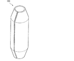
一方、上記のような問題を解決するために、電極組立体の中心部の空間に図1に図示したような巻芯部材100を挿入する方法が導入された。
On the other hand, in order to solve the above problems, a method of inserting the
巻芯部材100は、一般的に、一種のプレート(Plate)を巻いて形成された、断面が円形の管形状であって、長さ方向(管軸方向)に沿って一部分が切欠された形状からなる。
The
しかし、上記従来のリチウム二次電池における巻芯部材100は、外部圧力によって圧縮変形するなど容易に変形したり、または容易に破壊されたりするという問題がある。
However, the
特に、巻芯部材100が変形または破壊される場合には、電極組立体のセパレータが破壊されることがある。このようなセパレータの破壊は、正極電極板及び負極電極板間のショートを誘発し、円筒形リチウム二次電池の破壊または爆発を起こすことがあるという致命的な問題がある。
In particular, when the
また、巻芯部材100は外部圧力が作用する場合、その変形は特定の一ヶ所のみに集中する。従って、このような巻芯部材100の変形は、外部圧力が集中した所で集中的に発生し、これによって、電極組立体の特定の一方向のみに圧力が加わることになる。従って、電極組立体の変形をより深刻に発生させるという問題がある。
Further, when an external pressure is applied to the
そこで、本発明は、上記問題に鑑みてなされたものであり、本発明の目的とするところは、外圧の作用の際、変形を分散させることにより、外圧に対する電池安全性を向上させることが可能な、新規かつ改良された円筒形リチウム二次電池を提供することにある。 Therefore, the present invention has been made in view of the above problems, and an object of the present invention is to improve battery safety against external pressure by dispersing deformation during the action of external pressure. Another object of the present invention is to provide a new and improved cylindrical lithium secondary battery.
上記課題を解決するために、本発明のある観点によれば、第1電極板、第2電極板、及び第1電極板と第2電極板との間に介されたセパレータを備え、中心に所定の空間が形成された電極組立体と、長さ方向(管軸方向)に沿って切欠溝が形成された管形状からなり、長さ方向に沿って形成された少なくとも1つの折曲部を備えて、電極組立体の中心空間に挿入される巻芯部材と、電極組立体を収容するケースと、ケースの開口部を封鎖するキャップ組立体とを含むことを特徴とする、円筒形リチウム二次電池が提供される。 In order to solve the above-described problems, according to one aspect of the present invention, a first electrode plate, a second electrode plate, and a separator interposed between the first electrode plate and the second electrode plate are provided. An electrode assembly in which a predetermined space is formed and a tube shape in which a notch groove is formed along the length direction (tube axis direction), and at least one bent portion formed along the length direction is provided. A cylindrical lithium secondary battery comprising: a core member inserted into the central space of the electrode assembly; a case for housing the electrode assembly; and a cap assembly for sealing an opening of the case. A secondary battery is provided.
巻芯部材は、その横断面がなす円周上で切欠溝の反対側に配置される1つの折曲部を備えてもよい。 The winding core member may include a single bent portion disposed on the opposite side of the notch groove on the circumference formed by the cross section thereof.
巻芯部材は、その横断面がなす円周上で、切欠溝と巻芯部材の中心とを通る直線を基準にして対称に配置される2つの折曲部を備えてもよい。また、切欠溝の反対側で形成される、2つの折曲部間の中心角は120゜〜240゜であってもよい。 The winding core member may include two bent portions arranged symmetrically with respect to a straight line passing through the notch groove and the center of the winding core member on the circumference formed by the cross section. The central angle between the two bent portions formed on the opposite side of the notch groove may be 120 ° to 240 °.
切欠溝の両側端(切欠溝の両側にある巻芯部材の端部)は、巻芯部材の内部方向に曲げられていてもよい。また、切欠溝の両側端の接線がなす角は、120゜以下の角度をなしてもよい。 Both side ends of the cutout groove (end portions of the core member on both sides of the cutout groove) may be bent in the inner direction of the core member. Further, the angle formed by the tangent lines on both side ends of the notch groove may be an angle of 120 ° or less.
巻芯部材の高さは、電極組立体の高さの90%〜110%であってもよい。 The height of the core member may be 90% to 110% of the height of the electrode assembly.
また、本発明の別の観点によれば、第1電極板、第2電極板、及び第1電極板と第2電極板との間に介されたセパレータを備える巻取型電極組立体と、長さ方向に沿って形成された切欠溝、及び外圧の作用の際に作用する少なくとも1つの変形分散手段を備え、電極組立体の中心空間に挿入される管形状の巻芯部材と、電極組立体を収容するケースと、ケースの開口部を封鎖するキャップ組立体とを含むことを特徴とする、円筒形リチウム二次電池が提供される。 According to another aspect of the present invention, a winding electrode assembly comprising a first electrode plate, a second electrode plate, and a separator interposed between the first electrode plate and the second electrode plate; A tube-shaped core member inserted into the central space of the electrode assembly, the electrode assembly having a notch groove formed along the length direction, and at least one deformation dispersing means acting when an external pressure is applied; There is provided a cylindrical lithium secondary battery including a case for accommodating a solid body and a cap assembly for sealing an opening of the case.
巻芯部材は、その横断面がなす円周上で切欠溝の反対側に配置される1つの変形分散手段を備えてもよい。 The winding core member may include one deformation dispersing means disposed on the opposite side of the notch groove on the circumference formed by the cross section thereof.
巻芯部材は、その横断面がなす円周上で、切欠溝と巻芯部材の中心とを通る直線を基準にして対称に配置される2つの変形分散手段を備えてもよい。また、切欠溝の反対側で形成される、2つの変形分散手段間の中心角は120゜〜240゜であってもよい。 The core member may include two deformation dispersing means arranged symmetrically on the basis of a straight line passing through the notch groove and the center of the core member on the circumference formed by the cross section thereof. The central angle between the two deformation dispersing means formed on the opposite side of the notch groove may be 120 ° to 240 °.
切欠溝の両側端は、前記巻芯部材の内部方向に曲げられていてもよい。また、切欠溝の両側端の接線がなす角は120゜以下の角度をなしていてもよい。 Both side ends of the cutout groove may be bent in the inner direction of the core member. Further, the angle formed by the tangents on both sides of the notch groove may be an angle of 120 ° or less.
以上説明したように本発明によれば、外圧の作用の際、変形を分散させることにより、外圧に対する電池安全性を向上させることが可能な円筒形リチウム二次電池を提供することができる。 As described above, according to the present invention, it is possible to provide a cylindrical lithium secondary battery capable of improving battery safety against external pressure by dispersing deformation during the action of external pressure.
以下に添付図面を参照しながら、本発明の好適な実施の形態について詳細に説明する。なお、本明細書および図面において、実質的に同一の機能構成を有する構成要素については、同一の符号を付することにより重複説明を省略する。 Exemplary embodiments of the present invention will be described below in detail with reference to the accompanying drawings. In the present specification and drawings, components having substantially the same functional configuration are denoted by the same reference numerals, and redundant description is omitted.
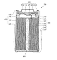
まず、本発明の一実施の形態に係る円筒形リチウム二次電池について説明する。図2aは本発明の一実施の形態に係る円筒形リチウム二次電池を説明するための斜視図であり、図2bは図2aのA−Aラインに係る断面図であり、図2cは図2aのB−Bラインに係る断面図である。 First, a cylindrical lithium secondary battery according to an embodiment of the present invention will be described. 2a is a perspective view for explaining a cylindrical lithium secondary battery according to an embodiment of the present invention, FIG. 2b is a sectional view taken along line AA of FIG. 2a, and FIG. 2c is FIG. 2a. It is sectional drawing which concerns on the BB line.
図2a〜図2cに示すように、本発明の一実施の形態に係る円筒形リチウム二次電池200は、充・放電の際、電圧差を発生させる電極組立体300と、電極組立体300を受け入れる円筒形のケース400と、円筒形ケース400の開口部に組立てられて電極組立体300が離脱しないようにするキャップ組立体500と、電極組立体300の中心空間に位置する巻芯部材600とを備える構造からなっている。
As shown in FIGS. 2a to 2c, a cylindrical lithium
電極組立体300は、正極活物質及び負極活物質の中のいずれかの1つ、例えば、正極活物質がコーティングされた第1電極板310と、正極活物質及び負極活物質の中の他の1つ、例えば、負極活物質がコーティングされた第2電極板320と、第1電極板310と第2電極板320との間に位置して、第1電極板310と第2電極板320とのショート(short)を防止し、リチウムイオンの移動のみを可能にするセパレータ330とからなる。また、第1電極板310、第2電極板320及びセパレータ330は、略円形で巻き取られて円筒形ケース400に収容される。また、第1電極板310には、一般的にアルミニウム(Al)材質からなり、上部に一定の長さが突出した第1電極タブ315が接合している。第2電極板320には、一般的にニッケル(Ni)材質からなり、下部に一定の長さが突出した第2電極タブ325が接合しているが、本発明において、上記の材質に限るものではない。併せて、電極組立体300の上・下部には、各々キャップ組立体500または円筒形ケース400と直接接触することを避けるために、上・下部絶縁プレート341、345が更に取付けられている。
The
円筒形ケース400は、電極組立体300を収容できるように、所定の空間を有し、一定の直径を有する円筒面410が形成されている。円筒面410の下部には、その円筒面410の下部を閉鎖する下面420が形成されている。円筒面410の上部は、電極組立体300を収容するために開口されている。一方、円筒形ケース400の下面420の中央に、電極組立体300の第1電極タブ315及び第2電極タブ325の中のいずれかの1つ、例えば、第2電極タブ325が接合することにより、円筒形ケース400自体は第2電極板320と同一な電極、例えば、負極端子の役割を遂行することになる。また、円筒形ケース400は、一般的に、アルミニウム(Al)、鉄(Fe)またはこれらの合金で形成される。併せて、円筒形ケース400には、上部でキャップ組立体500に圧力を加えるように片方に弓なりにたわんだクリンピング(crimping)部430が形成されている。更に、下部から上部方向へキャップ組立体500に圧力を加えるように、内側に凹んだビーディング(beading)部440が形成されている。
The
キャップ組立体500は、第1電極タブ315が熔接されると共に、過充電または異常発熱の際、形状が反転される導電性安全ベント510と、安全ベント510の上部に電気的及び機械的に連結されて、安全ベント510の反転の際、回路が途絶える印刷回路基板(PCB;Printed Circuit Board)520と、印刷回路基板520の上部に電気的及び機械的に連結されて所定温度以上で回路が途絶える陽性温度素子530と、陽性温度素子530の上部に電気的及び機械的に連結されて実際の電流を外部に印加する導電性電極キャップ540と、安全ベント510、印刷回路基板520、陽性温度素子530及び電極キャップ540の外周を覆う形状を成し、円筒形ケース400から上記の羅列した510〜540等を絶縁させる絶縁ガスケット550とからなる。この際、電極キャップ540は、電極組立体300の第1電極タブ315及び第2電極タブ325の中のいずれかの1つ、例えば、第1電極タブ315が接合して第1電極板310と同一の電極、例えば、正極端子の役割を遂行する。
The
巻芯部材600は、巻取型電極組立体300の中央の空間に挿入されて、巻取型電極組立体300が弛緩して解けることを防止し、外圧による巻取型電極組立体300の変形を防止する役割も遂行する。このような巻芯部材600は略管型からなっている。また、巻芯部材600の長さ方向に沿って切欠溝610が形成されている。切欠溝610の両側端は、巻芯部材600の内部方向に向けることが好ましい。また、管形状でなされる巻芯部材600は、その円周上に少なくとも1つの折曲部620を備えることが好ましい。
The winding
また、巻芯部材600は、電極組立体300が有する全体高さの約90%〜110%程度で形成されており、下段は第2電極タブ325上に位置する。この巻芯部材600の高さが、電極組立体300の高さの90%以下であれば、電極組立体300を固定及び支持する力があまりに弱く、また、110%以上であれば、キャップ組立体500の構成要素と接触するため好ましくない。
The
一方、図面上には図示してはいないが、円筒形ケース400には、電極組立体300間のリチウムイオンの移動を可能にするために電解液が注入される。電解液は、充・放電の際、電池の内部の正極及び負極で電気化学的反応により生成するリチウムイオン(Li−ion)の移動媒体の役割を果たす。電解液は、リチウム塩と高純度有機溶媒類の混合物である非水質系有機電解液であることができる。あるいは、高分子電解質を用いたポリマーであることもでき、ここで、電解液物質の種類を限るものではない。
On the other hand, although not shown in the drawing, an electrolytic solution is injected into the
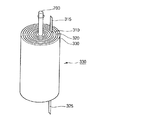
図3aは本発明の一実施の形態に係る円筒形リチウム二次電池の巻芯部材を説明するための斜視図であり、図3bは図3aのC−Cラインによる断面図である。 3A is a perspective view for explaining a core member of a cylindrical lithium secondary battery according to an embodiment of the present invention, and FIG. 3B is a cross-sectional view taken along the line CC of FIG. 3A.
図3a及び図3bを参照すると、本発明の一実施の形態に係る円筒形リチウム二次電池200の巻芯部材600は略管形状からなり、管形状の巻芯部材600の長さ方向に沿って切欠溝610が形成されており、切欠溝610が形成された両側端は巻芯部材600の内部方向に向かうように形成されている。この際、切欠溝610の両側端の接線がなす角(α)は120゜以下であることが好ましい。
3A and 3B, the
また、巻芯部材600は、管形状の巻芯部材600の長さ方向に沿って形成され、その横断面がなす円周上で切欠溝610と反対側に位置する1つの折曲部620を備えることが好ましい。
Further, the
折曲部620は、外圧が作用する場合、外圧が特定の一ヶ所のみに集中して、外圧が集中した所から変形が集中的に発生することを防止する。言い換えると、外圧が作用する場合、巻芯部材600の折曲部620が変形分散手段として作用して、折曲部620で変形が発生することによって、巻芯部材600の変形が1ヶ所に集中することなく分散する。これによって、巻芯部材600の変形による電極組立体300の変形及び破壊を防止することができる。
When external pressure is applied, the
一方、図4aは本発明の他の実施の形態に係る円筒形リチウム二次電池の巻芯部材を説明するための斜視図であり、図4bは図4aのD−Dラインによる断面図である。 On the other hand, FIG. 4a is a perspective view for explaining a core member of a cylindrical lithium secondary battery according to another embodiment of the present invention, and FIG. 4b is a cross-sectional view taken along line DD of FIG. 4a. .
図4a及び図4bを参照すると、本発明の他の実施の形態に係る円筒形リチウム二次電池200の巻芯部材600’は、図3a及び図3bに図示された本発明の一実施の形態に係る円筒形リチウム二次電池200の巻芯部材600と構造的に類似している。巻芯部材600’は管形状の巻芯部材600’の長さ方向に沿って形成され、その横断面がなす円周上で切欠溝610’を過ぎる直径を基準にして対称に位置する2つの折曲部620を備える構造のみ異なる。即ち、巻芯部材600’は2つの変形分散手段を備える構造からなる。
Referring to FIGS. 4a and 4b, a
より詳細に説明すると、本発明の他の実施の形態に係る円筒形リチウム二次電池200の巻芯部材600’は略管形状からなる。管形状の巻芯部材600’は長さ方向に沿って切欠溝610’及び変形分散手段として作用する2つの折曲部620’が形成されている。
More specifically, the core member 600 'of the cylindrical lithium
この際、切欠溝610’が形成された両側端は、巻芯部材600’の内部方向に向かうように形成されており、切欠溝610’の両側端の接線がなす角(α)は120゜以下であることが好ましい。
At this time, both side ends where the
また、上記変形分散手段として作用する2つの折曲部620’は、巻芯部材600’の横断面がなす円周上で切欠溝610’を過ぎる直径を基準にして対称に位置することが好ましい。また、2つの折曲部620’間の中心角の中、切欠溝610’の反対側で形成される中心角(β)は120゜〜240゜であることが好ましい。
Further, it is preferable that the two
図5は、本発明の一実施の形態に係る円筒形リチウム二次電池の製造方法を説明するための順次説明図である。 FIG. 5 is a sequential explanatory diagram for explaining a method of manufacturing the cylindrical lithium secondary battery according to one embodiment of the present invention.
図5を参照すると、本発明の一実施の形態に係る円筒形リチウム二次電池の製造方法は、電極組立体300の形成ステップS1、電極組立体300の結合ステップS2、巻芯部材600の挿入ステップS3、電解液注入ステップS4及びキャップ組立体500の結合ステップS5を含む。
Referring to FIG. 5, a method for manufacturing a cylindrical lithium secondary battery according to an embodiment of the present invention includes an
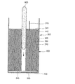
図6a〜図6dは、本発明の一実施の形態に係る円筒形リチウム二次電池の製造方法を説明するための図面である。以下では、図3と共に円筒形リチウム二次電池の製造方法を説明する。 6a to 6d are views for explaining a method of manufacturing a cylindrical lithium secondary battery according to an embodiment of the present invention. Below, the manufacturing method of a cylindrical lithium secondary battery is demonstrated with FIG.
図6aを参照すると、まず、電極組立体300の形成ステップS1では、第1電極板310、セパレータ330、第2電極板320を順次に積層し、これの一端には巻取軸700を結合した後、略円筒形で巻き取って電極組立体300を形成する。巻取の前に、第1電極板310には第1電極タブ315が、第2電極板320には第2電極タブ325が取付けられる。
Referring to FIG. 6a, first, in the formation step S1 of the
図6bを参照すると、電極組立体300の結合ステップS2では、略円筒形の電極組立体300を円筒形ケース400に結合する。結合後、電極組立体300から巻取軸700を分離する。この際、電極組立体300の中心部には略円形の空間が形成される。電極組立体300の結合前に巻取軸700を予め分離することもでき、本発明でその順序を限るのではない。また、円筒形ケース400には予め下部絶縁板341(図示してはいない)が結合している。
Referring to FIG. 6 b, in the coupling step S <b> 2 of the
図6cを参照すると、巻芯部材600の挿入ステップS3では、巻取軸700が分離して電極組立体300の中心部に形成された空間に、図3a、3b及び図4a、4bに図示されたような巻芯部材600を挿入する。
Referring to FIG. 6 c, in the insertion step S <b> 3 of the
ここで、巻芯部材600の挿入前に、電極組立体300の中、第1電極タブ315及び第2電極タブ325の中のいずれかの1つ、例えば、第2電極タブ325を円筒形ケース400の下面420に抵抗熔接などの方法により予め付着・固定することができる。従って、巻芯部材600は、第2電極タブ325の上面に接触したままで位置し、第2電極タブ325をより強く円筒形ケース400に結合させる役割もする。巻芯部材600は、電極組立体300が有する高さの約90%〜110%程度であることが好ましい。即ち、巻芯部材600の高さが電極組立体300の90%以下の場合、電極組立体300を固定及び支持する力があまりに弱くなるため好ましくない。また、110%以上の場合には、キャップ組立体500の構成要素と接触するため、好ましくない。
Here, before the
次に、電解液注入ステップS4では、電極組立体300の上段まで電解液を注入する。また、電解液は、電極組立体300で第1電極板310と第2電極板320との間に充・放電する際、リチウムイオンの移動を可能にする役割を遂行する。
Next, in the electrolyte injection step S4, the electrolyte is injected up to the upper stage of the
図6dを参照すると、キャップ組立体500の結合ステップS5では、円筒形ケース400の上部に複数の構成要素からなるキャップ組立体500を結合して、上述の電極組立体300、巻芯部材600及び電解液が外部に離脱または漏液しないようにして、円筒形リチウム二次電池200を形成する。
Referring to FIG. 6d, in the coupling step S5 of the
より詳細に説明すると、まず、円筒形ケース400の上部に略リング形態である絶縁ガスケット550を結合する。次に、その内部に、電極組立体300の第1電極タブ315または第2電極タブ325のうちのいずれか1つ、例えば第1電極タブ315と電気的に連結される導電性安全ベント510、印刷回路基板520、陽性温度素子530及び電極キャップ540を順次に結合する。
More specifically, first, an insulating
次に、絶縁ガスケット550の下段に該当する円筒形ケース400をビーディングして、内側方向に陥没したビーディング部440を形成する。その上段をクリンピングしてクリンピング部430を形成することによって、キャップ組立体500が外部に離脱しないようにし、円筒形リチウム二次電池200を形成する。
Next, the
上記のように、本発明の実施の形態に係る円筒形リチウム二次電池200は、管形状の巻芯部材600、600’が長さ方向に沿って形成されて、変形分散手段として作用する少なくとも1つの折曲部620、620’を備える。これにより、外圧が作用して巻芯部材600、600’の変形が発生しても、その変形が特定の一ヶ所のみに集中することなく、折曲部620、620’を通じて変形が分散するため、巻芯部材600、600’の変形による電極組立体300の変形または破壊を防止することができる。従って、本発明の実施の形態に係る円筒形リチウム二次電池200の外圧に対する安全性が向上する。
As described above, in the cylindrical lithium
以上、添付図面を参照しながら本発明の好適な実施形態について説明したが、本発明はかかる例に限定されない。当業者であれば、特許請求の範囲に記載された技術的思想の範疇内において、各種の変更例または修正例に想到し得ることは明らかであり、それらについても当然に本発明の技術的範囲に属するものと了解される。 As mentioned above, although preferred embodiment of this invention was described referring an accompanying drawing, this invention is not limited to this example. It is obvious for those skilled in the art that various changes or modifications can be conceived within the scope of the technical idea described in the claims. It is understood that it belongs to.
200 円筒形リチウム二次電池
300 電極組立体
310 第1電極板
315 第1電極タブ
320 第2電極板
325 第2電極タブ
330 セパレータ
341、345 絶縁プレート
400 円筒形ケース
410 円筒面
420 下面
430 クリンピング部
440 ビーディング部
500 キャップ組立体
510 安全ベント
520 印刷回路基板
530 陽性温度素子
540 電極キャップ
550 ガスケット
600、600’ 巻芯部材
610、610’ 切欠溝
620、620’ 折曲部
700 巻取軸
200 Cylindrical lithium
Claims (13)
長さ方向に沿って切欠溝が形成された管形状からなり、長さ方向に沿って内部方向に連続的に折曲形成された少なくとも1つの折曲部を備えて、前記電極組立体の前記中心空間に挿入される巻芯部材と;
前記電極組立体を収容するケースと;
前記ケースの開口部を封鎖するキャップ組立体と;
を含むことを特徴とする、円筒形リチウム二次電池。 A winding electrode assembly including a first electrode plate, a second electrode plate, and a separator interposed between the first electrode plate and the second electrode plate, and having a predetermined space at the center;
The electrode assembly has at least one bent portion that is formed in a tube shape in which a notch groove is formed along a length direction, and is continuously bent in an inner direction along the length direction. A core member inserted into the central space;
A case for accommodating the electrode assembly;
A cap assembly for sealing the opening of the case;
A cylindrical lithium secondary battery comprising:
長さ方向に沿って形成された切欠溝と、長さ方向に沿って連続的に折曲形成され外圧の作用の際に変形を分散させる折曲部とを備え、前記電極組立体の中心空間に挿入される管形状の巻芯部材と;
前記電極組立体を収容するケースと;
前記ケースの開口部を封鎖するキャップ組立体と;
を含むことを特徴とする、円筒形リチウム二次電池。 A winding electrode assembly comprising a first electrode plate, a second electrode plate, and a separator interposed between the first electrode plate and the second electrode plate;
A center space of the electrode assembly, comprising: a notch groove formed along the length direction; and a bent portion that is continuously bent along the length direction and that disperses the deformation under the action of external pressure. A tubular core member inserted into the tube;
A case for accommodating the electrode assembly;
A cap assembly for sealing the opening of the case;
A cylindrical lithium secondary battery comprising:
The cylindrical lithium secondary battery according to claim 12, wherein an angle formed by tangents on both ends of the cutout groove is 120 ° or less.
Applications Claiming Priority (1)
| Application Number | Priority Date | Filing Date | Title |
|---|---|---|---|
| KR1020050041423A KR100670454B1 (en) | 2005-05-18 | 2005-05-18 | Cylindrical Li Secondary Battery |
Publications (2)
| Publication Number | Publication Date |
|---|---|
| JP2006324245A JP2006324245A (en) | 2006-11-30 |
| JP4494366B2 true JP4494366B2 (en) | 2010-06-30 |
Family
ID=36593085
Family Applications (1)
| Application Number | Title | Priority Date | Filing Date |
|---|---|---|---|
| JP2006135464A Active JP4494366B2 (en) | 2005-05-18 | 2006-05-15 | Cylindrical lithium secondary battery |
Country Status (5)
| Country | Link |
|---|---|
| US (1) | US7955730B2 (en) |
| EP (1) | EP1724855B1 (en) |
| JP (1) | JP4494366B2 (en) |
| KR (1) | KR100670454B1 (en) |
| CN (1) | CN100463286C (en) |
Cited By (1)
| Publication number | Priority date | Publication date | Assignee | Title |
|---|---|---|---|---|
| US9337515B2 (en) | 2013-01-17 | 2016-05-10 | Samsung Sdi Co., Ltd. | Rechargeable battery |
Families Citing this family (30)
| Publication number | Priority date | Publication date | Assignee | Title |
|---|---|---|---|---|
| US8406901B2 (en) | 2006-04-27 | 2013-03-26 | Medtronic, Inc. | Sutureless implantable medical device fixation |
| US9492657B2 (en) | 2006-11-30 | 2016-11-15 | Medtronic, Inc. | Method of implanting a medical device including a fixation element |
| US8163408B2 (en) * | 2008-10-16 | 2012-04-24 | Lenovo (Singapore) Pte. Ltd. | Battery with pressure relief channel |
| KR100905180B1 (en) * | 2009-03-12 | 2009-06-29 | 이계설 | Multipurpose rolling device and rolling method |
| US20100305628A1 (en) * | 2009-05-29 | 2010-12-02 | Medtronic, Inc. | Elongate battery for implantable medical device |
| US8541131B2 (en) * | 2009-05-29 | 2013-09-24 | Medtronic, Inc. | Elongate battery for implantable medical device |
| US20100304209A1 (en) * | 2009-05-29 | 2010-12-02 | Medtronic, Inc. | Elongate battery for implantable medical device |
| US20100305627A1 (en) * | 2009-05-29 | 2010-12-02 | Medtronic, Inc. | Battery with suture hole |
| US8359098B2 (en) * | 2009-05-29 | 2013-01-22 | Medtronic, Inc. | Implantable medical device with exposed generator |
| US9099720B2 (en) * | 2009-05-29 | 2015-08-04 | Medtronic, Inc. | Elongate battery for implantable medical device |
| US8433409B2 (en) * | 2010-01-29 | 2013-04-30 | Medtronic, Inc. | Implantable medical device battery |
| CN102576910B (en) * | 2010-03-26 | 2016-03-02 | 丰田自动车株式会社 | Lithium rechargeable battery, vehicle and battery-mounted device |
| US10112045B2 (en) | 2010-12-29 | 2018-10-30 | Medtronic, Inc. | Implantable medical device fixation |
| US9775982B2 (en) | 2010-12-29 | 2017-10-03 | Medtronic, Inc. | Implantable medical device fixation |
| US9339197B2 (en) | 2012-03-26 | 2016-05-17 | Medtronic, Inc. | Intravascular implantable medical device introduction |
| US9717421B2 (en) | 2012-03-26 | 2017-08-01 | Medtronic, Inc. | Implantable medical device delivery catheter with tether |
| US10485435B2 (en) | 2012-03-26 | 2019-11-26 | Medtronic, Inc. | Pass-through implantable medical device delivery catheter with removeable distal tip |
| US9854982B2 (en) | 2012-03-26 | 2018-01-02 | Medtronic, Inc. | Implantable medical device deployment within a vessel |
| US9833625B2 (en) | 2012-03-26 | 2017-12-05 | Medtronic, Inc. | Implantable medical device delivery with inner and outer sheaths |
| US9220906B2 (en) | 2012-03-26 | 2015-12-29 | Medtronic, Inc. | Tethered implantable medical device deployment |
| US9351648B2 (en) | 2012-08-24 | 2016-05-31 | Medtronic, Inc. | Implantable medical device electrode assembly |
| KR101671176B1 (en) * | 2014-11-05 | 2016-11-01 | 주식회사 비츠로셀 | battery of wound type for enhancing durability and stability |
| US9811180B2 (en) | 2015-03-16 | 2017-11-07 | Lenovo (Singapore) Pte. Ltd. | Input device with gas vent(s) |
| US10651432B2 (en) | 2015-04-13 | 2020-05-12 | Cps Technology Holdings Llc | Systems and methods for a reinforcement column within a module body |
| USD798825S1 (en) * | 2016-01-04 | 2017-10-03 | Nomad Goods, Inc. | Cable with integrated in-line battery |
| US10874850B2 (en) | 2018-09-28 | 2020-12-29 | Medtronic, Inc. | Impedance-based verification for delivery of implantable medical devices |
| US11331475B2 (en) | 2019-05-07 | 2022-05-17 | Medtronic, Inc. | Tether assemblies for medical device delivery systems |
| CN112002873B (en) * | 2019-05-27 | 2022-03-18 | 万向一二三股份公司 | Pole piece with high bending strength of current collector |
| KR20230049050A (en) * | 2021-10-05 | 2023-04-12 | 주식회사 엘지에너지솔루션 | Electrode Assembly, Cylindrical Battery and System comprising the Same |
| SE2250078A1 (en) * | 2022-01-28 | 2023-07-29 | Northvolt Ab | Center pin for a secondary cell having an engagement profile |
Citations (5)
| Publication number | Priority date | Publication date | Assignee | Title |
|---|---|---|---|---|
| JPH08255631A (en) * | 1995-03-17 | 1996-10-01 | Asahi Chem Ind Co Ltd | Winding type battery |
| JPH09270251A (en) * | 1996-04-01 | 1997-10-14 | Kazuo Tagawa | Nonaqueous secondary battery and its gas ejection preventing method |
| JPH1167263A (en) * | 1997-08-21 | 1999-03-09 | Keihin Rika Kogyo:Kk | Center pin for battery |
| JP2003229177A (en) * | 2001-11-28 | 2003-08-15 | Sanyo Electric Co Ltd | Sealed battery |
| JP2005317441A (en) * | 2004-04-30 | 2005-11-10 | Kotobuki Seimitsu:Kk | Center pin of secondary battery and its manufacturing method |
Family Cites Families (9)
| Publication number | Priority date | Publication date | Assignee | Title |
|---|---|---|---|---|
| US5047068A (en) * | 1989-10-02 | 1991-09-10 | Eveready Battery Company, Inc. | Process of assembling a cell |
| JP3143951B2 (en) * | 1991-05-02 | 2001-03-07 | ソニー株式会社 | Non-aqueous electrolyte secondary battery |
| EP0872909B1 (en) * | 1995-01-27 | 2006-07-12 | Asahi Kasei EMD Corporation | Nonaqueous battery |
| JP3286880B2 (en) * | 1995-03-14 | 2002-05-27 | 株式会社京浜理化工業 | Non-aqueous secondary battery |
| JPH11224689A (en) * | 1998-02-04 | 1999-08-17 | Fujitsu Ltd | Wound lithium secondary battery and its electrode wound body |
| US6020084A (en) * | 1998-02-17 | 2000-02-01 | Alcatel | Electrochemical cell design with a hollow core |
| JP3786349B2 (en) | 2001-09-18 | 2006-06-14 | 日立マクセル株式会社 | Non-aqueous secondary battery |
| JP4207451B2 (en) * | 2002-04-19 | 2009-01-14 | パナソニック株式会社 | Cylindrical lithium ion secondary battery and manufacturing method thereof |
| JP5022621B2 (en) * | 2005-04-27 | 2012-09-12 | 三星エスディアイ株式会社 | Cylindrical lithium secondary battery |
-
2005
- 2005-05-18 KR KR1020050041423A patent/KR100670454B1/en active IP Right Grant
-
2006
- 2006-05-12 EP EP06113837A patent/EP1724855B1/en active Active
- 2006-05-15 JP JP2006135464A patent/JP4494366B2/en active Active
- 2006-05-18 CN CNB2006101108748A patent/CN100463286C/en active Active
- 2006-05-18 US US11/436,401 patent/US7955730B2/en active Active
Patent Citations (5)
| Publication number | Priority date | Publication date | Assignee | Title |
|---|---|---|---|---|
| JPH08255631A (en) * | 1995-03-17 | 1996-10-01 | Asahi Chem Ind Co Ltd | Winding type battery |
| JPH09270251A (en) * | 1996-04-01 | 1997-10-14 | Kazuo Tagawa | Nonaqueous secondary battery and its gas ejection preventing method |
| JPH1167263A (en) * | 1997-08-21 | 1999-03-09 | Keihin Rika Kogyo:Kk | Center pin for battery |
| JP2003229177A (en) * | 2001-11-28 | 2003-08-15 | Sanyo Electric Co Ltd | Sealed battery |
| JP2005317441A (en) * | 2004-04-30 | 2005-11-10 | Kotobuki Seimitsu:Kk | Center pin of secondary battery and its manufacturing method |
Cited By (1)
| Publication number | Priority date | Publication date | Assignee | Title |
|---|---|---|---|---|
| US9337515B2 (en) | 2013-01-17 | 2016-05-10 | Samsung Sdi Co., Ltd. | Rechargeable battery |
Also Published As
| Publication number | Publication date |
|---|---|
| US7955730B2 (en) | 2011-06-07 |
| EP1724855B1 (en) | 2012-06-13 |
| CN1893169A (en) | 2007-01-10 |
| KR100670454B1 (en) | 2007-01-16 |
| JP2006324245A (en) | 2006-11-30 |
| KR20060118959A (en) | 2006-11-24 |
| US20060275659A1 (en) | 2006-12-07 |
| CN100463286C (en) | 2009-02-18 |
| EP1724855A1 (en) | 2006-11-22 |
Similar Documents
| Publication | Publication Date | Title |
|---|---|---|
| JP4494366B2 (en) | Cylindrical lithium secondary battery | |
| US7655349B2 (en) | Cylindrical lithium secondary battery | |
| JP4701071B2 (en) | Lithium secondary battery | |
| JP4787046B2 (en) | Cylindrical lithium secondary battery | |
| KR101214011B1 (en) | Structure of electrode terminal and secondary battery using the same | |
| US20060099504A1 (en) | Secondary battery | |
| US8673483B2 (en) | Sealed battery | |
| KR101310731B1 (en) | Secondary battery | |
| WO2013031056A1 (en) | Rectangular battery | |
| US7754376B2 (en) | Cylindrical lithium secondary battery and method of fabricating the same | |
| KR101293208B1 (en) | Cap assembly for secondary battery | |
| KR101484099B1 (en) | Secondary battery | |
| JP4429253B2 (en) | Cylindrical lithium secondary battery | |
| JP4594244B2 (en) | Cylindrical lithium secondary battery | |
| KR20160138782A (en) | Rechageable battery | |
| KR100686811B1 (en) | Cylindrical Li Secondary Battery | |
| KR100646531B1 (en) | Cylindrical Li Secondary battery | |
| KR100696790B1 (en) | Cylindrical Li Secondary Battery | |
| KR100601499B1 (en) | Cylindrical Li Secondary Battery | |
| KR20060037828A (en) | Cylindrical li secondary battery |
Legal Events
| Date | Code | Title | Description |
|---|---|---|---|
| A131 | Notification of reasons for refusal |
Free format text: JAPANESE INTERMEDIATE CODE: A131 Effective date: 20091104 |
|
| A521 | Request for written amendment filed |
Free format text: JAPANESE INTERMEDIATE CODE: A523 Effective date: 20100128 |
|
| RD03 | Notification of appointment of power of attorney |
Free format text: JAPANESE INTERMEDIATE CODE: A7423 Effective date: 20100128 |
|
| TRDD | Decision of grant or rejection written | ||
| A01 | Written decision to grant a patent or to grant a registration (utility model) |
Free format text: JAPANESE INTERMEDIATE CODE: A01 Effective date: 20100316 |
|
| A01 | Written decision to grant a patent or to grant a registration (utility model) |
Free format text: JAPANESE INTERMEDIATE CODE: A01 |
|
| A61 | First payment of annual fees (during grant procedure) |
Free format text: JAPANESE INTERMEDIATE CODE: A61 Effective date: 20100407 |
|
| R150 | Certificate of patent or registration of utility model |
Ref document number: 4494366 Country of ref document: JP Free format text: JAPANESE INTERMEDIATE CODE: R150 Free format text: JAPANESE INTERMEDIATE CODE: R150 |
|
| FPAY | Renewal fee payment (event date is renewal date of database) |
Free format text: PAYMENT UNTIL: 20130416 Year of fee payment: 3 |
|
| FPAY | Renewal fee payment (event date is renewal date of database) |
Free format text: PAYMENT UNTIL: 20140416 Year of fee payment: 4 |
|
| R250 | Receipt of annual fees |
Free format text: JAPANESE INTERMEDIATE CODE: R250 |
|
| R250 | Receipt of annual fees |
Free format text: JAPANESE INTERMEDIATE CODE: R250 |
|
| R250 | Receipt of annual fees |
Free format text: JAPANESE INTERMEDIATE CODE: R250 |
|
| R250 | Receipt of annual fees |
Free format text: JAPANESE INTERMEDIATE CODE: R250 |
|
| R250 | Receipt of annual fees |
Free format text: JAPANESE INTERMEDIATE CODE: R250 |
|
| R250 | Receipt of annual fees |
Free format text: JAPANESE INTERMEDIATE CODE: R250 |
|
| R250 | Receipt of annual fees |
Free format text: JAPANESE INTERMEDIATE CODE: R250 |
|
| R250 | Receipt of annual fees |
Free format text: JAPANESE INTERMEDIATE CODE: R250 |
|
| R250 | Receipt of annual fees |
Free format text: JAPANESE INTERMEDIATE CODE: R250 |
|
| R250 | Receipt of annual fees |
Free format text: JAPANESE INTERMEDIATE CODE: R250 |
|
| R250 | Receipt of annual fees |
Free format text: JAPANESE INTERMEDIATE CODE: R250 |