JP4493608B2 - Atherectomy catheter - Google Patents
Atherectomy catheter Download PDFInfo
- Publication number
- JP4493608B2 JP4493608B2 JP2006059961A JP2006059961A JP4493608B2 JP 4493608 B2 JP4493608 B2 JP 4493608B2 JP 2006059961 A JP2006059961 A JP 2006059961A JP 2006059961 A JP2006059961 A JP 2006059961A JP 4493608 B2 JP4493608 B2 JP 4493608B2
- Authority
- JP
- Japan
- Prior art keywords
- inner tube
- atherectomy catheter
- tube
- distal end
- removal member
- Prior art date
- Legal status (The legal status is an assumption and is not a legal conclusion. Google has not performed a legal analysis and makes no representation as to the accuracy of the status listed.)
- Expired - Fee Related
Links
Images


Landscapes
- Surgical Instruments (AREA)
- Media Introduction/Drainage Providing Device (AREA)
Description
本発明は、管状の器官の内腔を狭窄または閉塞する閉塞物を除去するアテレクトミーカテーテルに関するものである。 The present invention relates to an atherectomy catheter that removes an obstruction that narrows or occludes the lumen of a tubular organ.
一般に、アテローム性動脈硬化症は、患者の血管内膜層の下側の中で脂肪の沈殿によって引き起こされる。最初は比較的柔軟なものが堆積し、時間が経つにつれてコレステロール成分が取り込まれて石灰化したアテローム層へ発達していくと考えられている。この発達したアテローム層により、血管内が狭窄状態または閉塞状態となり、血流が妨げられることになる。このまま放置しておくと、心臓の場合では狭心症や心筋梗塞、四肢の場合は虚血による手、足の指組織の壊死や、間欠跛行を引き起こす原因となる。 Generally, atherosclerosis is caused by the precipitation of fat within the patient's intimal layer. It is thought that a relatively soft thing is deposited at the beginning, and as time passes, a cholesterol component is taken in and develops into a calcified atheroma layer. Due to this developed atheroma layer, the blood vessel becomes stenotic or occluded, and blood flow is obstructed. If left untreated, it may cause angina or myocardial infarction in the case of the heart, necrosis of the hand and toe tissues due to ischemia in the case of the limbs, and intermittent claudication.
アテローム切除術はこのような発達した動脈硬化層をカテーテルによって血管の中から切除する手技である。通常、アテローム切除術は単独で行われず、バルーン血管形成術と併用される。さらに、動脈硬化層の切除とバルーン形成によってできた内腔を維持するために、ステントを留置するステント留置術が行われる。このような手技を行っても、多くの研究報告からも指摘されているとおり、ステントの内側にもまた新たに動脈硬化層が発達してくる場合がある。この場合は再度、アテローム切除術、バルーン血管形成術、ステント留置術を行うことがしばしばある。最近は、このステントに動脈硬化を防ぐ効能が期待される薬剤をコーティングして、狭窄率を低減するための研究がなされている。 Atherotomy is a procedure in which such a developed arteriosclerotic layer is excised from the blood vessel using a catheter. Usually, atherectomy is not performed alone and is used in combination with balloon angioplasty. Furthermore, in order to maintain the lumen formed by resection of the arteriosclerotic layer and balloon formation, a stent placement operation in which a stent is placed is performed. Even if such a procedure is performed, a new arteriosclerotic layer may develop inside the stent as pointed out by many research reports. In this case, atherectomy, balloon angioplasty, and stent placement are often performed again. Recently, studies have been made to reduce the stenosis rate by coating the stent with a drug expected to have an effect of preventing arteriosclerosis.
さて、アテローム切除術は、その適応に於いて、完全に血流が遮断されているような慢性閉塞に対して行われる場合がある。また血流が非常に少なくなるほど血管内膜が発達している場合等がある。これらのような病変に於いて様々な技術が公開されている。 Now, atherectomy may be performed for chronic occlusions where the blood flow is completely blocked in its indication. In some cases, the intima develops as the blood flow becomes very low. Various techniques have been published for such lesions.
例えば、特許文献1に記載されたものは、回転子自体に拡縮性を持たせており、血管において必要な内径の大きさが確保されるまで、回転子としての鞘手段の拡縮性を利用し、この鞘手段を引いたり押したりして幾度も通すようにしてある。 For example, the one described in Patent Document 1 has the expandability of the rotor itself, and uses the expandability of the sheath means as the rotor until the necessary inner diameter is secured in the blood vessel. The sheath means is pulled and pushed many times.
一方、血管を詰まらせるもう一つの原因として、血栓による閉塞がある。この血栓は血管が何らかの原因で出血することで発生した血栓が末梢に流れてきて堆積していく場合もあるが、前記アテローム層の表面は傷つきやすいため、何らかの原因でそのアテローム層の表面に傷が付くと、循環血中の血小板が集まり血栓を形成して血管を閉塞させる場合もあり、アテローム層と共存しているものもある。堆積した血栓を除去するためにバルーンによる除去技術が長年使用されている。 On the other hand, another cause of clogging blood vessels is occlusion due to thrombus. The thrombosis may be caused by blood vessels bleeding for some reason, and the thrombosis may flow and accumulate in the periphery, but the surface of the atheroma layer is easily damaged. In some cases, platelets in the circulating blood collect and form a thrombus to occlude blood vessels, and some coexist with the atheroma layer. Balloon removal techniques have been used for many years to remove accumulated thrombus.
ところで、特許文献1に記載のカテーテルでは、発達した動脈硬化層の病変あるいはさらに血栓を伴う病変等の狭窄または閉塞している病変部に対し、先端部が閉じているバスケット形状の鞘手段(剪断部材)を一旦貫通させる作業が必要である。また、鞘手段を回転させつつ、引いたり押したりすることを、血管の内径が必要な径まで拡大するまで幾度も繰り返す作業が必要となる。 By the way, in the catheter described in Patent Document 1, a basket-shaped sheath means (shearing) whose tip is closed against a narrowed or blocked lesion such as a lesion of the developed arteriosclerotic layer or a lesion with a thrombus. The operation | work which penetrates a member once is required. Further, it is necessary to repeat the pulling and pushing while rotating the sheath means until the inner diameter of the blood vessel is expanded to a necessary diameter.
しかしながら、閉塞に近似または閉塞している病変部の場合は、X線透視下においても、その造影剤が流れにくいため、病変部のどこからアプローチするかが判別しにくく、その病変部に鞘手段を正確に通すことが難しく、血管を損傷させたり、血管を突き破ったりすることが起こりやすい。このように、特許文献1に記載のカテーテルでは、多くの時間と労力が必要であるばかりでなく、その作業に熟練度を要するという欠点があった。 However, in the case of a lesion that is close to or occluded, the contrast agent is difficult to flow even under fluoroscopy, so it is difficult to determine where the lesion is approached, and a sheath means is attached to the lesion. It is difficult to pass accurately, and it is easy to damage the blood vessel and break through the blood vessel. As described above, the catheter described in Patent Document 1 has a drawback in that it requires not only a lot of time and labor but also a skill level for the work.
本発明の目的は、管状の器官の内腔を狭窄または閉塞する閉塞物を容易、迅速、確実かつ安全に除去することができるアテレクトミーカテーテルを提供することにある。 An object of the present invention is to provide an atherectomy catheter capable of easily, quickly, reliably and safely removing an obstruction that narrows or occludes a lumen of a tubular organ.
このような目的は、下記(1)〜(20)の本発明により達成される。
(1) 可撓性を有する外管と、
可撓性を有し、前記外管に対し、軸回りに回転可能でかつ軸方向に移動可能に、該外管内に挿通される内管と、
前記内管の先端部に固定されて前記外管内に収納され、管状の器官の内腔を狭窄または閉塞する閉塞物を除去する除去部材と、
前記内管に取り付けられ、前記内管内を挿通して前記内管が回転する際に軸となる可撓性を有する長尺状のガイド部材とを備えるアテレクトミーカテーテルであって、
前記閉塞物を除去する際に、前記除去部材は、前記外管の先端部から突出し、自己の弾性復元力により、径方向に拡開してその先端が開放した展開状態となり、
前記ガイド部材は、前記除去部材の先端部から突出し、
前記内管を介して前記除去部材を、前記ガイド部材を軸として回転させつつ、先端方向に移動させて、前記除去部材の先端部により前記閉塞物を掘削するよう構成されており、
前記除去部材は、軸方向に1対の角部を有する略菱形をなす複数の開口部を側面に有し、薄肉の略円筒状をなし、その先端部に、先端方向に突出した複数の突起部が周方向に沿って設けられており、
前記除去部材が前記外管内に収納されて収縮した状態のときは、前記開口部は、前記軸方向の1対の角部の角が小さくなり、前記軸方向に対して略垂直方向の1対の角部の角が大きくなるように変形しており、
前記除去部材が前記展開した状態のときは、前記開口部は、前記軸方向の1対の角部の角が前記収縮した状態のときよりも大きくなり、前記軸方向に対して略垂直方向の1対の角部の角が前記収縮した状態のときよりも小さくなっていることを特徴とするアテレクトミーカテーテル。
Such an object is achieved by the present invention of the following (1) to ( 20 ).
(1) a flexible outer tube;
An inner tube that has flexibility and is inserted into the outer tube so as to be rotatable about the axis and movable in the axial direction with respect to the outer tube;
A removal member fixed to the distal end of the inner tube and housed in the outer tube to remove an obstruction that narrows or occludes the lumen of the tubular organ;
An atherectomy catheter that is attached to the inner tube and includes a flexible elongated guide member that serves as an axis when the inner tube rotates through the inner tube,
When removing the obstruction, the removal member protrudes from the distal end portion of the outer tube, and expands in the radial direction by its own elastic restoring force, and is in a deployed state in which the distal end is opened,
The guide member protrudes from the tip of the removal member,
The removal member is configured to be excavated by the distal end portion of the removal member by moving the removal member in the distal direction while rotating about the guide member via the inner pipe ,
The removal member has a plurality of substantially rhombus-shaped openings having a pair of corners in the axial direction on the side surface, has a thin, substantially cylindrical shape, and has a plurality of protrusions protruding in the tip direction at the tip portion. Part is provided along the circumferential direction,
When the removal member is housed in the outer tube and contracted, the opening portion has a pair of corners in the axial direction that have a small corner, and a pair in the direction substantially perpendicular to the axial direction. It has been deformed so that the corners of
When the removal member is in the expanded state, the opening portion is larger in the corners of the pair of corners in the axial direction than in the contracted state, and is substantially perpendicular to the axial direction. An atherectomy catheter, wherein corners of a pair of corners are smaller than in the contracted state .
(2) 前記外管の内周と前記内管の外周との間に形成された第1流路と、前記内管の内腔で少なくとも一部が形成された第2流路とを有し、前記第1流路を介して、前記除去部材により掘削された前記閉塞物を含む流体を体外に排出し、前記第2流路を介して、前記管状の器官内に流体を注入し得るように構成されており、
前記第1流路を介して流体を排出すると共に、その流体の流量を調整し、かつ、前記第2流路を介して流体を注入すると共に、その流体の流量を調整し得る注入排出手段を備えている上記(1)に記載のアテレクトミーカテーテル。
(2) having a first flow path formed between the inner circumference of the outer pipe and the outer circumference of the inner pipe, and a second flow path formed at least partially in the lumen of the inner pipe The fluid containing the obstruction excavated by the removing member is discharged from the body through the first flow path, and the fluid can be injected into the tubular organ through the second flow path. Is composed of
Injecting / discharging means for discharging fluid through the first flow path, adjusting the flow rate of the fluid, injecting fluid through the second flow path, and adjusting the flow rate of the fluid atherectomy catheter according to the above (1) which are provided.
(3) 前記除去部材は、前記展開状態において側面の面積の4〜97%を占める複数の開口部を該側面に有する上記(1)または(2)に記載のアテレクトミーカテーテル。 (3) The atherectomy catheter according to (1) or (2), wherein the removing member has a plurality of openings on the side surface that occupy 4 to 97% of an area of the side surface in the deployed state.
(4) 前記除去部材は、網状をなしている上記(1)ないし(3)のいずれかに記載のアテレクトミーカテーテル。 (4) The atherectomy catheter according to any one of (1) to (3), wherein the removing member has a net shape.
(5) 前記除去部材は、前記展開状態において、その先端部が前記ガイド部材に対して離間している上記(1)ないし(4)のいずれかに記載のアテレクトミーカテーテル。 (5) The atherectomy catheter according to any one of (1) to (4), wherein a tip of the removing member is separated from the guide member in the deployed state.
(6) 前記除去部材の少なくとも一部は、形状記憶合金で構成されている上記(1)ないし(5)のいずれかに記載のアテレクトミーカテーテル。 (6) The atherectomy catheter according to any one of (1) to (5), wherein at least a part of the removal member is made of a shape memory alloy.
(7) 前記外管に対して前記内管の軸方向の移動を固定する第1の固定手段を有する上記(1)ないし(6)のいずれかに記載のアテレクトミーカテーテル。 (7) The atherectomy catheter according to any one of (1) to (6), further including first fixing means for fixing the axial movement of the inner tube with respect to the outer tube.
(8) 前記第1の固定手段は、前記内管の軸方向の移動を固定したとき、前記外管に対して前記内管の軸回りの回転を許容し、前記外管の内周と前記内管の外周との間に形成された第1流路の流体の通過を遮断する機能を有する上記(7)に記載のアテレクトミーカテーテル。 (8) When the movement of the inner pipe in the axial direction is fixed, the first fixing means allows the outer pipe to rotate around the axis of the inner pipe, and the inner circumference of the outer pipe and the The atherectomy catheter according to (7) above, which has a function of blocking the passage of fluid in the first flow path formed between the outer periphery of the inner tube.
(9) 前記外管の基端部に、該外管の内周と前記内管の外周との間に形成された第1流路に連通するポート部を有するコネクタが設けられている上記(1)ないし(8)のいずれかに記載のアテレクトミーカテーテル。 (9) A connector having a port portion communicating with a first flow path formed between an inner periphery of the outer tube and an outer periphery of the inner tube is provided at a base end portion of the outer tube. The atherectomy catheter according to any one of 1) to (8).
(10) 前記外管の基端部に、該外管の内周と前記内管の外周との間に形成された第1流路に連通するポート部を有するコネクタが設けられており、
前記第1の固定手段は、前記コネクタに設けられている上記(7)または(8)に記載のアテレクトミーカテーテル。
(10) A connector having a port portion communicating with the first flow path formed between the inner periphery of the outer tube and the outer periphery of the inner tube is provided at the base end portion of the outer tube,
The atherectomy catheter according to (7) or (8), wherein the first fixing means is provided in the connector.
(11) 前記第1の固定手段は、前記コネクタの基端部の内側に設置された弁体と、前記弁体を前記内管側に押圧またはその押圧を解除する操作部とを有する上記(10)に記載のアテレクトミーカテーテル。 (11) The first fixing unit includes a valve body installed inside a proximal end portion of the connector, and an operation unit that presses the valve body toward the inner tube or releases the press. The atherectomy catheter according to 10).
(12) 前記内管の先端部の外周に設けられた凸部と、前記内管の先端部が挿入される管状体とを有し、
前記管状体が前記内管の前記凸部より基端側に位置するように、前記管状体内に前記内管の先端部が挿入され、前記内管の外周と前記管状体の内周との間に前記除去部材の基端部が配置された状態で、前記管状体を前記内管の外周上に固着することにより、前記除去部材が前記内管に対して固定されている上記(1)ないし(11)のいずれかに記載のアテレクトミーカテーテル。
( 12 ) having a convex portion provided on the outer periphery of the distal end portion of the inner tube, and a tubular body into which the distal end portion of the inner tube is inserted,
The distal end portion of the inner tube is inserted into the tubular body so that the tubular body is located on the proximal side from the convex portion of the inner tube, and between the outer periphery of the inner tube and the inner periphery of the tubular body. The removal member is fixed to the inner tube by fixing the tubular body on the outer periphery of the inner tube in a state where the base end portion of the removal member is disposed on the inner tube. The atherectomy catheter according to any one of ( 11 ).
(13) 前記内管に前記ガイド部材を取り付ける際、前記内管に対して前記ガイド部材を固定する第2の固定手段を有する上記(1)ないし(12)のいずれかに記載のアテレクトミーカテーテル。 ( 13 ) The atherectomy catheter according to any one of (1) to ( 12 ), further including second fixing means for fixing the guide member to the inner tube when the guide member is attached to the inner tube.
(14) 前記第2の固定手段は、前記内管の基端部に設けられたハブと、前記ガイド部材の基端部に設けられ、前記内管のハブと嵌合可能なハブとを有する上記(13)に記載のアテレクトミーカテーテル。 ( 14 ) The second fixing means includes a hub provided at a proximal end portion of the inner tube, and a hub provided at a proximal end portion of the guide member and fitable with the hub of the inner tube. The atherectomy catheter according to ( 13 ) above.
(15) 前記内管のハブと前記ガイド部材のハブとが嵌合した際、前記ガイド部材の先端側が前記除去部材の先端から1〜8mm突出する上記(14)に記載のアテレクトミーカテーテル。 ( 15 ) The atherectomy catheter according to ( 14 ), wherein when the hub of the inner tube and the hub of the guide member are fitted, the distal end side of the guide member protrudes 1 to 8 mm from the distal end of the removal member.
(16) 前記内管および前記除去部材を回転させる回転補助具が接続可能である上記(13)ないし(15)のいずれかに記載のアテレクトミーカテーテル。 ( 16 ) The atherectomy catheter according to any one of ( 13 ) to ( 15 ), wherein a rotation assisting tool that rotates the inner tube and the removal member is connectable.
(17) 前記ガイド部材は、超弾性合金、ステンレス鋼および樹脂のうちのいずれかで構成されている上記(1)ないし(16)のいずれかに記載のアテレクトミーカテーテル。 ( 17 ) The atherectomy catheter according to any one of (1) to ( 16 ), wherein the guide member is made of any one of a superelastic alloy, stainless steel, and a resin.
(18) 前記ガイド部材の少なくとも先端部は、X線透視下で視認可能なX線造影部材で構成されているか、もしくはX線造影部が設けられている上記(1)ないし(17)のいずれかに記載のアテレクトミーカテーテル。 ( 18 ) At least the distal end portion of the guide member is made of an X-ray contrast member that is visible under X-ray fluoroscopy, or any of the above (1) to ( 17 ) in which an X-ray contrast portion is provided An atherectomy catheter according to the above.
(19) 前記ガイド部材の先端部に、先端に向って外径が漸減するテーパ状部が設けられ、該テーパ状部の先端が丸みを帯びている上記(1)ないし(18)のいずれかに記載のアテレクトミーカテーテル。 ( 19 ) Any one of the above (1) to ( 18 ), wherein a tapered portion whose outer diameter gradually decreases toward the distal end is provided at the distal end of the guide member, and the distal end of the tapered portion is rounded. The atherectomy catheter described in 1.
(20) 前記外管は、外層と中間層と内層とを有し、前記中間層は、補強材として機能し、前記内層は、低摩擦材料により構成されている上記(1)ないし(19)のいずれかに記載のアテレクトミーカテーテル。 ( 20 ) The outer tube includes an outer layer, an intermediate layer, and an inner layer, the intermediate layer functions as a reinforcing material, and the inner layer is made of a low-friction material (1) to ( 19 ). An atherectomy catheter according to any one of the above.
本発明によれば、閉塞物を除去する際に、除去部材が径方向に拡開してその先端が開放した展開状態となるので、除去部材が前進しながら回転することで、管状の器官(例えば、血管等)の内腔を狭窄または閉塞する閉塞物を容易、迅速かつ確実に掘削して除去することができる。 According to the present invention, when removing the obstruction, since the removal member expands in the radial direction and the distal end is opened, the removal member rotates while moving forward, so that the tubular organ ( For example, an obstruction that narrows or occludes a lumen of a blood vessel or the like can be easily and quickly excavated and removed.
また、除去部材がガイド部材を軸として回転するので、容易、確実かつ安定的に除去部材を回転させることができる。 Moreover, since the removal member rotates about the guide member, the removal member can be rotated easily, reliably and stably.
このため、管状の器官を損傷させたり、突き破ることなく、また熟練度を要することなく、閉塞物を容易、迅速、確実かつ安全に除去することができる。 For this reason, the obstruction can be easily, quickly, reliably and safely removed without damaging or breaking through the tubular organ and without requiring skill.
以下、本発明のアテレクトミーカテーテルを添付図面に示す好適な実施形態に基づいて詳細に説明する。 Hereinafter, the atherectomy catheter of the present invention will be described in detail based on preferred embodiments shown in the accompanying drawings.
なお、本実施形態では、本発明のアテレクトミーカテーテルを血管の内腔を狭窄または閉塞する閉塞物を除去するカテーテルに適用した場合を説明する。 In this embodiment, the case where the atherectomy catheter of the present invention is applied to a catheter for removing an obstruction that narrows or occludes the lumen of a blood vessel will be described.
図1は、本発明のアテレクトミーカテーテルの実施形態を示す側面図、図2は、図1に示すアテレクトミーカテーテルの外管およびコネクタの側面図である。また、図3は、図1に示すアテレクトミーカテーテルの断面図であって、図3(a)は、図1中のA−A線での断面図、図3(b)は、図1中のB−B線での断面図、図3(c)は、図1中のC−C線での断面図、図3(d)は、図1中のD−D線での断面図である。また、図4は、図1に示すアテレクトミーカテーテルの内管および除去部材の側面図、図5は、図1に示すアテレクトミーカテーテルであって、除去部材が展開状態のときの側面図、図6は、図5に示すアテレクトミーカテーテルの除去部材側を示す側面図、図7は、図1に示すアテレクトミーカテーテルの内管の先端部側を示す側面図、図8は、図7に示す内管の先端部に除去部材を固定した状態を示す部分断面図、図9は、図1に示すアテレクトミーカテーテルのコネクタおよび押し子の断面図、図10は、図1に示すアテレクトミーカテーテルのガイド部材の側面図、図11は、図5に示すアテレクトミーカテーテルにおけるガイド部材を閉塞物に突き当てた状態を示す図である。また、図12は、図5に示すアテレクトミーカテーテルの作用(除去部材が閉塞物を除去するまで)を説明するための図であって、図12(a)は、除去部材が閉塞物に突き当たった状態を示す図、図12(b)は、除去部材が閉塞物を掘削して除去している状態を示す図、図12(c)は、除去部材が閉塞物の殆どを除去した状態を示す図である。 FIG. 1 is a side view showing an embodiment of the atherectomy catheter of the present invention, and FIG. 2 is a side view of the outer tube and connector of the atherectomy catheter shown in FIG. 3 is a cross-sectional view of the atherectomy catheter shown in FIG. 1. FIG. 3 (a) is a cross-sectional view taken along line AA in FIG. 1, and FIG. 3 (b) is a cross-sectional view in FIG. FIG. 3C is a cross-sectional view taken along the line CC in FIG. 1, and FIG. 3D is a cross-sectional view taken along the line DD in FIG. . 4 is a side view of the inner tube and the removal member of the atherectomy catheter shown in FIG. 1, FIG. 5 is a side view of the atherectomy catheter shown in FIG. 1 when the removal member is in the deployed state, and FIG. 5 is a side view showing the removal member side of the atherectomy catheter shown in FIG. 5, FIG. 7 is a side view showing the distal end side of the inner tube of the atherectomy catheter shown in FIG. 1, and FIG. 8 is the distal end of the inner tube shown in FIG. FIG. 9 is a sectional view of the connector and pusher of the atherectomy catheter shown in FIG. 1, and FIG. 10 is a side view of the guide member of the atherectomy catheter shown in FIG. FIG. 11 is a view showing a state in which the guide member in the atherectomy catheter shown in FIG. 12 is a diagram for explaining the operation of the atherectomy catheter shown in FIG. 5 (until the removal member removes the obstruction). FIG. 12 (a) shows that the removal member hits the obstruction. FIG. 12B is a diagram illustrating a state, FIG. 12B is a diagram illustrating a state where the removal member excavates and removes the obstruction, and FIG. 12C is a state where most of the obstruction is removed by the removal member. FIG.
なお、説明の都合上、図1、図2、図4〜図12において、左側を「先端」、右側を「基端」として説明する。また、図3では、断面の部分のみを図示している。 For convenience of explanation, in FIGS. 1, 2, and 4 to 12, the left side is referred to as “tip” and the right side is referred to as “base end”. Further, in FIG. 3, only the cross section is shown.
これらの図に示すアテレクトミーカテーテル(カテーテル)1は、動脈等の血管内(管状の器官内)に生じた不要物、すなわち、血管(管状の器官)の内腔を狭窄または閉塞する不要物である閉塞物(血管閉塞物)を掘削(破壊)(破砕)して除去し(血管の疎通を行い)、血流を確保する医療用デバイスである。 The atherectomy catheter (catheter) 1 shown in these drawings is an unnecessary object generated in a blood vessel (tubular organ) such as an artery, that is, an unnecessary object for narrowing or blocking the lumen of the blood vessel (tubular organ). It is a medical device that secures blood flow by excavating (breaking) (crushing) and removing an obstruction (blood vessel obstruction) (performing blood vessel communication).
図1に示すように、アテレクトミーカテーテル1は、外管2と、外管2の基端部に設けられたコネクタ4と、外管2に対し、軸回りに回転可能でかつ軸方向に移動可能に、外管2内に挿通される内管3と、内管3の先端部に固定(装着)されて外管2内に収納され、血管の内腔を狭窄または閉塞する閉塞物を掘削して除去する除去部材5と、内管3に取り付けられ、内管3内を挿通して内管3が回転する際に軸となるガイド部材6とを備えている。以下、アテレクトミーカテーテルを、単に、「カテーテル」とも言う。また、前記閉塞物には、血管の内腔を閉塞する不要物は勿論、完全に閉塞しないまでも内腔を狭窄する種々の不要物も含まれる。具体的には、閉塞物としては、例えば、血栓、脂肪斑、動脈硬化層等が挙げられる。
As shown in FIG. 1, the atherectomy catheter 1 is rotatable about an axis and movable in the axial direction with respect to the
図1および図2に示すように、外管2は、基端部から先端部まで一定の径の円筒状(筒状)をなしている。この外管2は、図3(a)および図3(b)に示すように、内層21と、その外周に設けられた中間層22と、その外周に設けられた外層23とで構成された三層構造をなし、血管内に挿入されたとき、血管の曲がりに沿って自在に曲がることができるよう可撓性を有している。
As shown in FIGS. 1 and 2, the
また、外管2の寸法は、特に限定されないが、例えば、外径(直径)は、1.5〜3.5mm程度、内径(直径)は、1.0〜3.0mm程度、軸方向の長さは、30〜150cm程度とするのが好ましい。
The dimensions of the
外管2の内層21は、低摩擦材料により構成されているのが好ましい。この内層21の構成材料としては、例えば、ポリテトラフルオロエチレン等のフッ素系樹脂等が挙げられる。
The
また、外管2の中間層22は、補強材として機能するように構成されているのが好ましい。この中間層22の構成材料としては、例えば、ステンレス鋼、タングステン、ニッケル、チタン、ニッケル・チタン合金、ニッケル・コバルト合金、ニッケル・マンガン合金、炭素繊維等が挙げられる。すなわち、中間層22は、前記金属の線材または炭素繊維等の所定の線材を編み込んでなるメッシュ等で構成されるのが好ましい。
The
また、外管2の外層23の構成材料としては、例えば、ポリエチレン、ポリプロピレン、ポリブタジエン等のポリオレフィン、ポリ塩化ビニル、ポリウレタン、ポリエーテルポリウレタン、エチレン−酢酸ビニル共重合体、ポリエチレンテレフタレート、ポリブチレンテレフタレート、ポリアミド、ポリエーテルポリアミド、ポリエステルポリアミド、スチレン系、ポリオレフィン系、ポリウレタン系、ポリエステル系、ポリアミド系、ポリブタジエン系、トランスポリイソプレン系、フッ素ゴム系、塩素化ポリエチレン系等の各種熱可塑性エラストマー等が挙げられ、さらには、これらのうちの2種以上をブレンドしたもの、またはこれらのうちの2種以上を積層したものを用いてもよい。
Examples of the constituent material of the
このような外管2は、血管内の閉塞物の除去に際し、X線透視下で視認可能なように、少なくとも先端部のX線造影性を高めるのが好ましい。この場合、例えば、少なくとも前記外層23の構成材料に、例えば、硫酸バリウム、白金、金、タングステン等のX線不透過材料を配合するか、前記X線不透過材料で構成されるX線造影部を設ければよい。本実施形態では、図1および図2に示すように、外管2の先端部に、X線造影部(マーカー)24が設けられている。
Such an
図3(a)および図3(b)に示すように、内管3は、外管2内を挿通し得る外径を有する円筒状(筒状)をなしており、この内管3の外周と外管2の内周との間に第1流路Xが形成されている。この内管3も外管2と同様、可撓性を有している。
As shown in FIGS. 3A and 3B, the
内管3の構成材料としては、例えば、ポリエーテルエーテルケトン、ポリエチレンテレフタレート、ポリブチレンテレフタレート等のポリエステル、ポリイミド、ポリアミド、ポリエーテルポリアミド、ポリエステルポリアミド、ABS樹脂、AS樹脂、ポリテトラフルオロエチレン等のフッ素系樹脂が挙げられ、さらには、これらのうちの2種以上をブレンドしたもの、またはこれらのうちの2種以上を積層したものを用いてもよい。
The constituent material of the
また、内管3の寸法は、特に限定されないが、例えば、外径(直径)は、0.8〜1.8mm程度、内径(直径)は、0.5〜1.5mm程度、軸方向の長さは、50〜170cm程度とするのが好ましい。
The dimensions of the
図4に示すように、このような内管3の先端部には、血管内に生じた閉塞物を掘削して除去する除去部材5が固定されている。
As shown in FIG. 4, a
この除去部材5は、図1に示すように、外管2内に収納されて収縮した(つぼまった)状態(収納状態)と、図5に示すように、外管2の先端部から突出し、自己の弾性復元力により、径方向に拡開してその先端が開放した展開状態とを採り得るように構成されている。除去部材5は、展開状態のときが自然状態であり、そのときは、除去部材5の先端部は、ガイド部材6に対して離間している。閉塞物を除去する際は、除去部材5は、外管2の先端部から突出し、自己の弾性復元力により、径方向に拡開してその先端が開放した展開状態となる。
As shown in FIG. 1, the
以下、代表的に、展開状態のときの除去部材5について説明する。
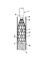
図4および図5に示すように、除去部材5は、薄肉の略円筒状(概ねすり鉢状)をなしており、その先端部に、先端方向に突出した複数の突起部51が周方向に沿って設けられている。これにより、閉塞物を容易かつ確実に掘削することができる。
Hereinafter, the
As shown in FIGS. 4 and 5, the
また、除去部材5の側壁部は、網状をなしている。すなわち、除去部材5は、複数の開口部53を側面(側壁部)に有している。これにより、除去部材5によって掘削された閉塞物を開口部53を介して排出させることができ、また、所定の流体を開口部53を介して血管内に注入することができる。
Further, the side wall portion of the removing
除去部材5の側面の面積に対する開口部53の占める割合は、4〜97%程度であるのが好ましく、20〜70%程度であるのがより好ましい。
The ratio of the
開口部53の占める割合が前記下限値未満であると、他の条件によっては、除去部材5が自己拡張できなくなることがある。
If the ratio of the
また、開口部53の占める割合が前記上限値を超えると、他の条件によっては、掘削時において、除去部材5が、ねじれたり、展開した状態から収縮した状態へ変化することがある。
Moreover, when the ratio which the
また、開口部53は、軸方向に1対の角部を有する略菱形をなしており、除去部材5が外管2内に収納されて収縮した状態のときは、その菱形の開口部53は、軸方向の1対の角部の角が小さくなり、他の1対の角部(軸方向に対して略垂直方向の1対の角部)の角が大きくなるように変形している。
The
そして、除去部材5が外管2の先端部から突出すると、菱形の開口部53は、軸方向の1対の角部の角が前記収縮した状態のときよりも大きくなり、他の1対の角部の角が前記収縮した状態のときよりも小さくなって、除去部材5は、径方向に拡開してその先端が開放した展開状態となる(自然状態に戻る)。
And when the
このような構成により、除去部材5は円滑かつ確実に展開状態となることができる。また、先端部の突起部51は、山型(V字状)に尖った形状となる。
With such a configuration, the removing
除去部材5の構成材料としては、例えば、形状記憶合金等を用いるのが好ましい。この形状記憶合金としては、例えば、Ti−Ni、Ti−Ni−Cu等のTi−Ni系合金、Cu−Al−Mn、Cu−Al−Ni等のCu系合金、Fe−Mn−Si等のFe系合金、Au−Cd、Ag−Cd系合金、Ni−Mn−Ga、Fe−Pd等の強磁性形状記憶合金等が挙げられる。
As a constituent material of the removing
除去部材5の寸法は、特に限定されないが、その肉厚は、例えば、0.1〜0.3mm程度とするのが好ましい。
Although the dimension of the
この除去部材5の内管3の先端部への固定(固着)方法は、特に限定されないが、例えば、下記のように行なうことができる。
The method of fixing (fixing) the
図7に示すように、先端部の外周にリング状の凸部31が設けられた内管3を用意する。この場合、例えば、内管3の先端部の外周に、光硬化性樹脂を塗布し、この光硬化性樹脂を硬化させて凸部31を形成することができる。
As shown in FIG. 7, an
また、内管3に被せる図6に示す管状体55を用意する。この管状体55の内径(直径)は、凸部31の外径(直径)に、除去部材5の肉厚の2倍の値を加えた値以下とされる。また、管状体55の構成材料としては、例えば、ステンレス鋼等が挙げられる。
Moreover, the
図8に示すように、除去部材5の基端部をつぼませて、管状体55内に挿入し、その除去部材5の基端部および管状体55内に、内管3をその基端側から挿入し、管状体55を凸部31に当接させて止める。管状体55は、内管3の凸部31より基端側に位置している。これにより、内管3の凸部31より基端側の外周に管状体55が被せられ、内管3の外周と管状体55の内周との間に除去部材5の基端部が配置される。
As shown in FIG. 8, the proximal end portion of the
そして、除去部材5の基端を管状体55の基端より、所定長、基端側に突出させ、その基端部にチューブ56を被せる。チューブ56の構成材料としては、例えば、各種の樹脂材料等が挙げられる。
Then, the base end of the removing
次に、チューブ56の基端側から光硬化性樹脂57を供給して硬化させ、管状体55とともに除去部材5の端部を内管3に固定する。続けて、チューブ56の端部と内管3の段差を埋めるように光硬化性樹脂57を塗布して硬化させる。このように、管状体55を内管3の外周上に光硬化性樹脂57(接着剤)で固着することにより、除去部材5が内管3に対して固定される。
Next, the
なお、例えば、管状体55をカシメて、除去部材5を内管3の先端部に固定(固着)してもよい。
For example, the
また、図4に示すように、内管3の基端部には、回転補助手段として、パイプ71が被せられている。これにより、内管3の基端部の回転トルク伝達性は、先端部の回転トルク伝達性よりも大きくなり、内管3および除去部材5が、外管3内で軸周りに回転しやすくなる。パイプ71の構成材料としては、例えば、ステンレス鋼等の各種の金属材料が挙げられる。
As shown in FIG. 4, a
なお、回転補助手段は、パイプ71に限らず、例えば、内管3の基端部を、例えば、ステンレス鋼等の各種の金属材料で構成することで実現してもよい。
The rotation assisting means is not limited to the
また、内管3の基端(基端部)には、内管ハブ72が設けられている。この内管ハブ72には、軸心に沿う孔(図示せず)が設けられると共に、側面に手指で回転操作し得るように平面状に形成されたツマミ部73が設けられ、さらにその基端側には、連結部74が設けられている。
An
図2に示すように、外管2の基端部に設けられたコネクタ4は、Yコネクタであり、ポート部4Aを有しており、このコネクタ4の内周と内管3の外周との間に第1流路X(図3(a)および図3(b)参照)が形成されている。すなわち、ポート部4Aは、第1流路Xに連通している。このコネクタ4は、締結部材20を締め付けることで、外管2の基端部に連結される。
As shown in FIG. 2, the connector 4 provided at the proximal end portion of the
また、図9に示すように、コネクタ4の基端部の内側には、リング状の弁体41が設置されており、さらに、その基端側には、押し子(操作部)42が、軸方向に移動可能に設けられている。
Further, as shown in FIG. 9, a ring-shaped
弁体41は、その内周に沿って形成されたリブ41aを有し、コネクタ4の基端部に拡径して形成された段差部43において、コネクタ4の先端側に移動しないように係止されている。
The
押し子42の外側部42aの内周面には、コネクタ4の基端部の外周面に形成された雄ネジ43aと螺合する雌ネジ42bが形成されている。この場合、押し子42を所定方向に回転させる(回転操作すると)と、押し子42は、コネクタ4に沿って、先端方向に移動し、これにより、コネクタ4の基端部および弁体41が内管3側に押圧され、また、押し子42を前記と逆方向に回転させる(回転操作すると)と、押し子42は、コネクタ4に沿って、基端方向に移動し、これにより、コネクタ4の基端部および弁体41の前記内管3側への押圧が解除されるようになっている。
On the inner peripheral surface of the
押し子42が先端方向に移動してコネクタ4の基端部および弁体41が内管3側に押圧されると、外管2に対して内管3の軸方向の移動が固定(阻止)される。このとき、外管2に対して内管3の軸回りの回転は許容され、また、弁体41により、第1流路Xの流体の通過は遮断(封止)される。
When the
また、押し子42が基端方向に移動してコネクタ4の基端部および弁体41の内管3側への押圧が解除されると、外管2に対して内管3の軸方向の移動が許容される。
Further, when the
従って、前記弁体41および押し子42により、第1の固定手段の主要部が構成される。
Therefore, the
図10に示すように、ガイド部材6は、可撓性を有する長尺状をなしている。すなわち、可撓性を有する線状体である。閉塞物を除去する際は、ガイド部材6は、除去部材5の先端部から所定長突出する。このガイド部材6は、閉塞物に突き当たることで、その閉塞物の位置を特定することができ、さらに、ガイド部材6の先端部を閉塞物の中心に突き刺して内管3および除去部材5が回転する際の軸とすることにより、除去部材5の回転軸のブレを抑制でき、血管壁の損傷を防止することができ、確実に閉塞物を除去できる。
As shown in FIG. 10, the
ガイド部材6の寸法は、特に限定されないが、その外径は、0.5〜1.2mm程度であるのが好ましい。
Although the dimension of the
また、ガイド部材6の先端部には、先端に向って外径が漸減するテーパ状部62が設けられており、このテーパ状部62の先端は、丸みを帯びている。テーパ状部62の先端を丸めることにより、安全性が向上する。
Further, a tapered
また、ガイド部材6は、血管内の閉塞物の除去に際し、X線透視下で視認可能なように、少なくとも先端部のX線造影性を高めるのが好ましい。すなわち、ガイド部材6の少なくとも先端部は、X線造影部材で構成されているか、もしくはX線造影部(マーカー)が設けられているのが好ましい。
Moreover, it is preferable that the
また、ガイド部材6は、超弾性合金、ステンレス鋼および樹脂のうちのいずれかで構成されているのが好ましい。すなわち、ガイド部材6の構成材料としては、例えば、ニッケル、チタン、ニッケル・チタン合金、ニッケル・コバルト合金、ニッケル・マンガン合金、ステンレス鋼、炭素鋼、樹脂等が挙げられる。
Moreover, it is preferable that the
また、ガイド部材6の基端部には、ガイドハブ63が設けられている。図1および図5に示すように、ガイド部材6を内管3内に挿通し、ガイドハブ63を内管3の内管ハブ72の連結部74に嵌合することで、ガイド部材6が内管3に対して取り付けられ、固定される。
A
従って、前記ガイドハブ63および内管ハブ72により第2の固定手段の主要部が構成される。
Therefore, the
また、ガイドハブ63と内管ハブ72の連結部74とが嵌合してガイド部材6が内管3に取り付けられた状態において、ガイド部材6の先端側が、除去部材5の先端から所定長さ、突出するようになっている。この所定長は、1〜8mm程度であるのが好ましく、2〜5mm程度であるのがより好ましい。
Further, in a state where the
前記所定長を前記範囲内にすることにより、安全性を保持しつつ、内管3および除去部材5が回転する際の軸として確実に機能することができる。
By setting the predetermined length within the above range, the
図3(d)に示すように、ガイドハブ63には、横断面形状が略半円状をなし、軸方向に貫通するルーメン64が形成されている。ガイドハブ63が内管3の内管ハブ72に嵌合すると、内管3の内腔と、内管ハブ72の内腔と、ガイドハブ63のルーメン64とが連通し、これらにより、第2流路Yが形成される。
As shown in FIG. 3D, the
また、ガイドハブ63の基端部には、連結部65が設けられている。
ここで、このアテレクトミーカテーテル1では、内管3、除去部材5およびガイド部材6を回転させる図示しない回転補助具が接続可能になっている。その回転補助具は、例えば、ガイドハブ63の連結部65に接続されるように構成されている。
A connecting
Here, in the atherectomy catheter 1, a rotation assisting tool (not shown) that rotates the
また、第1流路Xを介して、除去部材5により掘削された閉塞物を含む流体を体外に排出し得るように構成され、また、第2流路Yを介して、血管内に所定の流体を注入し得るように構成されている。
In addition, the fluid containing the obstruction excavated by the removing
この場合、例えば、コネクタ4のポート部4Aに、図示しない注入排出装置(注入排出手段)の排出部が接続され、ガイドハブ63の連結部65に、その注入排出装置の注入部が接続される。
In this case, for example, a discharge portion of an injection / discharge device (injection / discharge means) (not shown) is connected to the
そして、注入排出装置の排出部の作動(駆動)により、除去部材5によって掘削された閉塞物を含む流体が吸引されて排出される。この際、その流体の流量の調整、すなわち、単位時間当りの流量の調整を行なうようにすることもできる。
And by the action | operation (drive) of the discharge part of an injection | pouring / exhaust apparatus, the fluid containing the obstruction | occlusion excavated by the
また、注入排出装置の注入部の作動(駆動)により、血管内に所定の流体が注入される。この際、その流体の流量の調整、すなわち、単位時間当りの流量の調整を行なうようにすることもできる。 A predetermined fluid is injected into the blood vessel by the operation (drive) of the injection part of the injection / discharge device. At this time, the flow rate of the fluid can be adjusted, that is, the flow rate per unit time can be adjusted.
次に、アテレクトミーカテーテル1の作用(使用方法の一例)について説明する。
血管内の閉塞物を除去する処置を行なう場合、予め、外管2に対し、除去部材5が固定された内管3が挿通され、その除去部材5が縮径した状態で外管2の先端側の内部に収納されている。この内管3および外管2を、シース(図示せず)を介して、ガイドワイヤ操作(図示せず)にて、血管内の目的部位まで挿入する。そのときの状況は、X線造影等によってモニタされる。
Next, an operation (an example of a usage method) of the atherectomy catheter 1 will be described.
When the treatment for removing the obstruction in the blood vessel is performed, the
内管3および外管2が血管の目的部位に到達した時点で、ガイドワイヤが抜去され、次いで、ガイド部材6が、その先端から内管3内に挿入され、そのガイドハブ63を内管ハブ72に嵌合する。これにより、ガイド部材6が内管3に対して固定される。
When the
次いで、コネクタ4の押し子42を回転操作して弁体41を緩め、その状態で内管3を押し進める。これにより、図11に示すように、除去部材5は、外管2の先端部から突出し、自己の弾性復元力により、径方向に拡開してその先端が開放した展開状態となる。また、ガイド部材6が除去部材5の設定された長さ分だけ先端から突出した状態となり、ガイド部材6の先端部が、閉塞物(病変部)Hに当接する。そして、コネクタ4の押し子42を回転操作して弁体41を内側に締め付け、内管3を回転可能なように外管2に固定する。
Next, the
次いで、図12(a)に示すように、アテレクトミーカテーテル1全体を先端方向に移動させて、ガイド部材6を前進させ、ガイド部材6の先端部を血管内の閉塞物Hに突き刺し、内管3をガイド部材6を軸として回転させる。これにより、除去部材5がガイド部材6を軸として回転しつつ、先端方向に移動する。
Next, as shown in FIG. 12A, the entire atherectomy catheter 1 is moved in the distal direction, the
これにより、図12(b)に示すように、ガイド部材6が閉塞物H中に入り込むことに伴い、除去部材5の先端部の突起部51が閉塞物Hを掘削してゆく。
As a result, as shown in FIG. 12B, as the
このように、ガイド部材6および除去部材5の前進移動と回転とを行うことで、図12(c)に示すように、除去部材5が閉塞物Hを確実に除去することができる。この場合、閉塞物Hが、例えば血管内に生じている石灰化病変等の固いアテローム等であっても、確実に掘削して除去することができる。
この除去された閉塞物Hは、第1流路Xを介して外部に排出される。
Thus, by performing forward movement and rotation of the
The removed obstruction H is discharged to the outside through the first flow path X.
以上説明したように、このアテレクトミーカテーテル1によれば、除去部材5を血管の病変部まで移動し、そこで、除去部材5が血管内の閉塞物Hに突き当たった状態でその除去部材5を回転させながら先端方向に移動させると、除去部材5の突起部51によって閉塞物Hを徐々に掘削して除去することができるので、従来技術のようなガイドワイヤを病変部に一旦貫通させて繰り返し前後に動かすという作業が不要になり、閉塞物Hを容易、迅速かつ確実に掘削して除去することができる。
As described above, according to the atherectomy catheter 1, the
また、除去部材5がガイド部材6を軸として回転するので、容易、確実かつ安定的に除去部材5を回転させることができる。
Further, since the removing
このため、血管を損傷させたり、突き破ることなく、また熟練度を要することなく、閉塞物Hを容易、迅速、確実かつ安全に除去することができる。 For this reason, the obstruction | occlusion object H can be removed easily, rapidly, reliably and safely, without damaging or breaking through a blood vessel and without requiring skill.
また、掘削された閉塞物Hは、第1流路Xを介して外部に排出されるので、安全性が高い。 Moreover, since the excavated obstruction | occlusion object H is discharged | emitted outside via the 1st flow path X, safety | security is high.
なお、閉塞物Hを除去する際、第1流路Xから掘削された閉塞物Hを排出させると共に、第2流路Yから生理食塩水等を注入させることもできる。このようにすれば、掘削された閉塞物Hを外部に排出させる際の吸引によって発生した圧力差によって血管を攣縮させたり、変形させることなく、閉塞物Hを除去し続けることができる。 In addition, when removing the obstruction | occlusion object H, while occluding the obstruction | occlusion object H excavated from the 1st flow path X, physiological saline etc. can also be inject | poured from the 2nd flow path Y. In this way, it is possible to continue removing the obstruction H without causing the blood vessel to contract or deform due to a pressure difference generated by suction when the excavated obstruction H is discharged to the outside.
以上のように、閉塞物Hを除去できることにより、血管を疎通して血流を確保することができる共に、次のデバイスの道筋ができる、次の治療ステップ(バルーン、ステント等での拡張)等を容易に行えるようになる。 As described above, by removing the obstruction H, the blood vessel can be communicated and blood flow can be secured, and the path of the next device can be created, the next treatment step (expansion with a balloon, a stent, etc.), etc. Can be easily performed.
以上、本発明のアテレクトミーカテーテルを、図示の実施形態に基づいて説明したが、本発明はこれに限定されるものではなく、各部の構成は、同様の機能を有する任意の構成のものに置換することができる。また、本発明に、他の任意の構成物が付加されていてもよい。 Although the atherectomy catheter of the present invention has been described based on the illustrated embodiment, the present invention is not limited to this, and the configuration of each part is replaced with an arbitrary configuration having the same function. be able to. In addition, any other component may be added to the present invention.
また、本発明のアテレクトミーカテーテルにより閉塞物を除去する部位(箇所)は、血管に限らず、この他、例えば、胆管、尿道等が挙げられる。
また、閉塞物としては、例えば、血栓、脂肪斑、動脈硬化層、結石等が挙げられる。
Moreover, the site | part (location) from which an obstruction is removed by the atherectomy catheter of this invention is not restricted to a blood vessel, In addition, a bile duct, a urethra, etc. are mentioned, for example.
Moreover, as an obstruction, a thrombus, a fatty spot, an arteriosclerosis layer, a calculus, etc. are mentioned, for example.
1 アテレクトミーカテーテル
2 外管
20 締結部材
21 内層
22 中間層
23 外層
24 X線造影部
3 内管
31 凸部
4 コネクタ
41 弁体
41a リブ
42 押し子
42a 外側部
42b 雌ネジ
43 段差部
43a 雄ネジ
4A ポート部
5 除去部材
51 突起部
53 開口部
55 管状体
56 チューブ
57 光硬化性樹脂
6 ガイド部材
62 テーパ状部
63 ガイドハブ
64 ルーメン
65 連結部
71 パイプ
72 内管ハブ
73 ツマミ部
74 連結部
100 血管
H 閉塞物
X 第1流路
Y 第2流路
DESCRIPTION OF SYMBOLS 1
Claims (20)
可撓性を有し、前記外管に対し、軸回りに回転可能でかつ軸方向に移動可能に、該外管内に挿通される内管と、
前記内管の先端部に固定されて前記外管内に収納され、管状の器官の内腔を狭窄または閉塞する閉塞物を除去する除去部材と、
前記内管に取り付けられ、前記内管内を挿通して前記内管が回転する際に軸となる可撓性を有する長尺状のガイド部材とを備えるアテレクトミーカテーテルであって、
前記閉塞物を除去する際に、前記除去部材は、前記外管の先端部から突出し、自己の弾性復元力により、径方向に拡開してその先端が開放した展開状態となり、
前記ガイド部材は、前記除去部材の先端部から突出し、
前記内管を介して前記除去部材を、前記ガイド部材を軸として回転させつつ、先端方向に移動させて、前記除去部材の先端部により前記閉塞物を掘削するよう構成されており、
前記除去部材は、軸方向に1対の角部を有する略菱形をなす複数の開口部を側面に有し、薄肉の略円筒状をなし、その先端部に、先端方向に突出した複数の突起部が周方向に沿って設けられており、
前記除去部材が前記外管内に収納されて収縮した状態のときは、前記開口部は、前記軸方向の1対の角部の角が小さくなり、前記軸方向に対して略垂直方向の1対の角部の角が大きくなるように変形しており、
前記除去部材が前記展開した状態のときは、前記開口部は、前記軸方向の1対の角部の角が前記収縮した状態のときよりも大きくなり、前記軸方向に対して略垂直方向の1対の角部の角が前記収縮した状態のときよりも小さくなっていることを特徴とするアテレクトミーカテーテル。 A flexible outer tube;
An inner tube that has flexibility and is inserted into the outer tube so as to be rotatable about the axis and movable in the axial direction with respect to the outer tube;
A removal member fixed to the distal end of the inner tube and housed in the outer tube to remove an obstruction that narrows or occludes the lumen of the tubular organ;
An atherectomy catheter that is attached to the inner tube and includes a flexible elongated guide member that serves as an axis when the inner tube rotates through the inner tube,
When removing the obstruction, the removal member protrudes from the distal end portion of the outer tube, and expands in the radial direction by its own elastic restoring force, and is in a deployed state in which the distal end is opened,
The guide member protrudes from the tip of the removal member,
The removal member is configured to be excavated by the distal end portion of the removal member by moving the removal member in the distal direction while rotating about the guide member via the inner pipe ,
The removal member has a plurality of substantially rhombus-shaped openings having a pair of corners in the axial direction on the side surface, has a thin, substantially cylindrical shape, and has a plurality of protrusions protruding in the tip direction at the tip portion. Part is provided along the circumferential direction,
When the removal member is housed in the outer tube and contracted, the opening portion has a pair of corners in the axial direction that have a small angle, and a pair in a direction substantially perpendicular to the axial direction. It has been deformed so that the corners of
When the removal member is in the unfolded state, the opening is larger than that in the contracted state in which the corners of the pair of corners in the axial direction are substantially perpendicular to the axial direction. An atherectomy catheter, wherein corners of a pair of corners are smaller than in the contracted state .
前記第1流路を介して流体を排出すると共に、その流体の流量を調整し、かつ、前記第2流路を介して流体を注入すると共に、その流体の流量を調整し得る注入排出手段を備えている請求項1に記載のアテレクトミーカテーテル。 A first flow path formed between an inner circumference of the outer pipe and an outer circumference of the inner pipe, and a second flow path formed at least in part by a lumen of the inner pipe, The fluid including the obstruction excavated by the removing member is discharged from the body through one flow path, and the fluid can be injected into the tubular organ through the second flow path. And
Injecting / discharging means for discharging fluid through the first flow path, adjusting the flow rate of the fluid, injecting fluid through the second flow path, and adjusting the flow rate of the fluid The atherectomy catheter according to claim 1 provided .
前記第1の固定手段は、前記コネクタに設けられている請求項7または8に記載のアテレクトミーカテーテル。 A connector having a port portion communicating with a first flow path formed between an inner periphery of the outer tube and an outer periphery of the inner tube is provided at a base end portion of the outer tube,
The atherectomy catheter according to claim 7 or 8, wherein the first fixing means is provided in the connector.
前記管状体が前記内管の前記凸部より基端側に位置するように、前記管状体内に前記内管の先端部が挿入され、前記内管の外周と前記管状体の内周との間に前記除去部材の基端部が配置された状態で、前記管状体を前記内管の外周上に固着することにより、前記除去部材が前記内管に対して固定されている請求項1ないし11のいずれかに記載のアテレクトミーカテーテル。 A convex portion provided on the outer periphery of the distal end portion of the inner tube, and a tubular body into which the distal end portion of the inner tube is inserted,
The distal end portion of the inner tube is inserted into the tubular body so that the tubular body is located on the proximal side from the convex portion of the inner tube, and between the outer periphery of the inner tube and the inner periphery of the tubular body. The removal member is fixed to the inner tube by fixing the tubular body on the outer periphery of the inner tube in a state where the base end portion of the removal member is disposed on the inner tube. An atherectomy catheter according to any one of the above.
Priority Applications (5)
| Application Number | Priority Date | Filing Date | Title |
|---|---|---|---|
| JP2006059961A JP4493608B2 (en) | 2006-03-06 | 2006-03-06 | Atherectomy catheter |
| DE602007003871T DE602007003871D1 (en) | 2006-03-06 | 2007-03-05 | atherectomy |
| EP07004427A EP1832240B1 (en) | 2006-03-06 | 2007-03-05 | Atherectomy catheter |
| AT07004427T ATE452587T1 (en) | 2006-03-06 | 2007-03-05 | ATHERECTOMY CATHETER |
| US11/714,148 US7833240B2 (en) | 2006-03-06 | 2007-03-06 | Atherectomy catheter |
Applications Claiming Priority (1)
| Application Number | Priority Date | Filing Date | Title |
|---|---|---|---|
| JP2006059961A JP4493608B2 (en) | 2006-03-06 | 2006-03-06 | Atherectomy catheter |
Publications (3)
| Publication Number | Publication Date |
|---|---|
| JP2007236471A JP2007236471A (en) | 2007-09-20 |
| JP2007236471A5 JP2007236471A5 (en) | 2009-04-16 |
| JP4493608B2 true JP4493608B2 (en) | 2010-06-30 |
Family
ID=38582619
Family Applications (1)
| Application Number | Title | Priority Date | Filing Date |
|---|---|---|---|
| JP2006059961A Expired - Fee Related JP4493608B2 (en) | 2006-03-06 | 2006-03-06 | Atherectomy catheter |
Country Status (1)
| Country | Link |
|---|---|
| JP (1) | JP4493608B2 (en) |
Families Citing this family (11)
| Publication number | Priority date | Publication date | Assignee | Title |
|---|---|---|---|---|
| US8425549B2 (en) | 2002-07-23 | 2013-04-23 | Reverse Medical Corporation | Systems and methods for removing obstructive matter from body lumens and treating vascular defects |
| US8585713B2 (en) | 2007-10-17 | 2013-11-19 | Covidien Lp | Expandable tip assembly for thrombus management |
| US8926680B2 (en) | 2007-11-12 | 2015-01-06 | Covidien Lp | Aneurysm neck bridging processes with revascularization systems methods and products thereby |
| US8066757B2 (en) | 2007-10-17 | 2011-11-29 | Mindframe, Inc. | Blood flow restoration and thrombus management methods |
| US10123803B2 (en) | 2007-10-17 | 2018-11-13 | Covidien Lp | Methods of managing neurovascular obstructions |
| US8088140B2 (en) | 2008-05-19 | 2012-01-03 | Mindframe, Inc. | Blood flow restorative and embolus removal methods |
| US9220522B2 (en) | 2007-10-17 | 2015-12-29 | Covidien Lp | Embolus removal systems with baskets |
| US9198687B2 (en) * | 2007-10-17 | 2015-12-01 | Covidien Lp | Acute stroke revascularization/recanalization systems processes and products thereby |
| US8940003B2 (en) | 2008-02-22 | 2015-01-27 | Covidien Lp | Methods and apparatus for flow restoration |
| EP2452637B1 (en) * | 2009-09-29 | 2014-04-09 | Terumo Kabushiki Kaisha | Catheter with mechanism for removing object that occludes duct of tubular organ |
| WO2021153089A1 (en) * | 2020-01-29 | 2021-08-05 | テルモ株式会社 | Catheter |
Family Cites Families (4)
| Publication number | Priority date | Publication date | Assignee | Title |
|---|---|---|---|---|
| US5395311A (en) * | 1990-05-14 | 1995-03-07 | Andrews; Winston A. | Atherectomy catheter |
| CA2161640C (en) * | 1993-04-29 | 2005-04-12 | Thomas V. Ressemann | Expandable intravascular occlusion material removal device |
| US20010031981A1 (en) * | 2000-03-31 | 2001-10-18 | Evans Michael A. | Method and device for locating guidewire and treating chronic total occlusions |
| WO2001076458A2 (en) * | 2000-04-07 | 2001-10-18 | Bacchus Vascular, Inc. | Methods and device for percutaneous remote endarterectomy |
-
2006
- 2006-03-06 JP JP2006059961A patent/JP4493608B2/en not_active Expired - Fee Related
Also Published As
| Publication number | Publication date |
|---|---|
| JP2007236471A (en) | 2007-09-20 |
Similar Documents
| Publication | Publication Date | Title |
|---|---|---|
| JP4493608B2 (en) | Atherectomy catheter | |
| US7833240B2 (en) | Atherectomy catheter | |
| US10959749B2 (en) | Medical device and treatment method | |
| US9943323B2 (en) | Retrieval systems and methods for use thereof | |
| EP3302311B1 (en) | Flexible intravascular treatment devices | |
| JP2022133393A (en) | Rapid aspiration thrombectomy system and method | |
| JP5928522B2 (en) | Thrombus capture catheter | |
| JP2020022878A (en) | System and method for crossing and treating occlusion | |
| US6544276B1 (en) | Exchange method for emboli containment | |
| JP2004097807A (en) | Thrombus capturing catheter | |
| US20180103971A1 (en) | Medical device and treatment method | |
| EP3164088B1 (en) | Improved atherectomy device | |
| US20160213396A1 (en) | Catheter with an auger and method of use thereof | |
| JP6785106B2 (en) | Medical system | |
| JP2007330696A (en) | Atherectomy catheter |
Legal Events
| Date | Code | Title | Description |
|---|---|---|---|
| A521 | Written amendment |
Free format text: JAPANESE INTERMEDIATE CODE: A523 Effective date: 20090303 |
|
| A621 | Written request for application examination |
Free format text: JAPANESE INTERMEDIATE CODE: A621 Effective date: 20090303 |
|
| A131 | Notification of reasons for refusal |
Free format text: JAPANESE INTERMEDIATE CODE: A131 Effective date: 20091208 |
|
| A977 | Report on retrieval |
Free format text: JAPANESE INTERMEDIATE CODE: A971007 Effective date: 20091210 |
|
| A521 | Written amendment |
Free format text: JAPANESE INTERMEDIATE CODE: A523 Effective date: 20100205 |
|
| TRDD | Decision of grant or rejection written | ||
| A01 | Written decision to grant a patent or to grant a registration (utility model) |
Free format text: JAPANESE INTERMEDIATE CODE: A01 Effective date: 20100309 |
|
| A01 | Written decision to grant a patent or to grant a registration (utility model) |
Free format text: JAPANESE INTERMEDIATE CODE: A01 |
|
| A61 | First payment of annual fees (during grant procedure) |
Free format text: JAPANESE INTERMEDIATE CODE: A61 Effective date: 20100406 |
|
| R150 | Certificate of patent or registration of utility model |
Free format text: JAPANESE INTERMEDIATE CODE: R150 |
|
| FPAY | Renewal fee payment (event date is renewal date of database) |
Free format text: PAYMENT UNTIL: 20130416 Year of fee payment: 3 |
|
| FPAY | Renewal fee payment (event date is renewal date of database) |
Free format text: PAYMENT UNTIL: 20130416 Year of fee payment: 3 |
|
| FPAY | Renewal fee payment (event date is renewal date of database) |
Free format text: PAYMENT UNTIL: 20140416 Year of fee payment: 4 |
|
| LAPS | Cancellation because of no payment of annual fees |