JP4493294B2 - Inserts for walls, especially body openings - Google Patents
Inserts for walls, especially body openings Download PDFInfo
- Publication number
- JP4493294B2 JP4493294B2 JP2003193300A JP2003193300A JP4493294B2 JP 4493294 B2 JP4493294 B2 JP 4493294B2 JP 2003193300 A JP2003193300 A JP 2003193300A JP 2003193300 A JP2003193300 A JP 2003193300A JP 4493294 B2 JP4493294 B2 JP 4493294B2
- Authority
- JP
- Japan
- Prior art keywords
- wall
- flange
- neck
- opening
- insertion part
- Prior art date
- Legal status (The legal status is an assumption and is not a legal conclusion. Google has not performed a legal analysis and makes no representation as to the accuracy of the status listed.)
- Expired - Fee Related
Links
- 238000003780 insertion Methods 0.000 claims description 57
- 230000037431 insertion Effects 0.000 claims description 57
- 230000002093 peripheral effect Effects 0.000 claims description 19
- 239000004033 plastic Substances 0.000 claims description 12
- 229920003023 plastic Polymers 0.000 claims description 12
- 239000012530 fluid Substances 0.000 claims description 3
- 239000000853 adhesive Substances 0.000 description 25
- 230000001070 adhesive effect Effects 0.000 description 25
- 239000002184 metal Substances 0.000 description 9
- 238000007789 sealing Methods 0.000 description 5
- 230000008901 benefit Effects 0.000 description 4
- 238000004519 manufacturing process Methods 0.000 description 4
- 239000000155 melt Substances 0.000 description 4
- 238000002844 melting Methods 0.000 description 3
- 230000008018 melting Effects 0.000 description 3
- 239000003566 sealing material Substances 0.000 description 3
- 238000005260 corrosion Methods 0.000 description 2
- 230000007797 corrosion Effects 0.000 description 2
- 230000005489 elastic deformation Effects 0.000 description 2
- 238000010438 heat treatment Methods 0.000 description 2
- 238000000034 method Methods 0.000 description 2
- 230000000717 retained effect Effects 0.000 description 2
- 229920002994 synthetic fiber Polymers 0.000 description 2
- 230000009471 action Effects 0.000 description 1
- 230000002411 adverse Effects 0.000 description 1
- 230000004075 alteration Effects 0.000 description 1
- 239000011324 bead Substances 0.000 description 1
- 230000005540 biological transmission Effects 0.000 description 1
- 238000006243 chemical reaction Methods 0.000 description 1
- 238000002485 combustion reaction Methods 0.000 description 1
- 239000002131 composite material Substances 0.000 description 1
- 238000010586 diagram Methods 0.000 description 1
- 238000006073 displacement reaction Methods 0.000 description 1
- 238000009826 distribution Methods 0.000 description 1
- 238000012423 maintenance Methods 0.000 description 1
- 239000000463 material Substances 0.000 description 1
- 238000012986 modification Methods 0.000 description 1
- 230000004048 modification Effects 0.000 description 1
- 239000012768 molten material Substances 0.000 description 1
- 238000010422 painting Methods 0.000 description 1
- 230000000149 penetrating effect Effects 0.000 description 1
- 230000008569 process Effects 0.000 description 1
- 238000009827 uniform distribution Methods 0.000 description 1
- 238000009736 wetting Methods 0.000 description 1
Images


Classifications
-
- B—PERFORMING OPERATIONS; TRANSPORTING
- B62—LAND VEHICLES FOR TRAVELLING OTHERWISE THAN ON RAILS
- B62D—MOTOR VEHICLES; TRAILERS
- B62D25/00—Superstructure or monocoque structure sub-units; Parts or details thereof not otherwise provided for
- B62D25/24—Superstructure sub-units with access or drainage openings having movable or removable closures; Sealing means therefor
-
- F—MECHANICAL ENGINEERING; LIGHTING; HEATING; WEAPONS; BLASTING
- F16—ENGINEERING ELEMENTS AND UNITS; GENERAL MEASURES FOR PRODUCING AND MAINTAINING EFFECTIVE FUNCTIONING OF MACHINES OR INSTALLATIONS; THERMAL INSULATION IN GENERAL
- F16B—DEVICES FOR FASTENING OR SECURING CONSTRUCTIONAL ELEMENTS OR MACHINE PARTS TOGETHER, e.g. NAILS, BOLTS, CIRCLIPS, CLAMPS, CLIPS OR WEDGES; JOINTS OR JOINTING
- F16B19/00—Bolts without screw-thread; Pins, including deformable elements; Rivets
- F16B19/008—Bolts without screw-thread; Pins, including deformable elements; Rivets with sealing means
Description
【0001】
【発明の属する技術分野】
本発明は、壁、特に車体の開口部への挿入のための挿入部品であって、開口部を通過する頚部と、挿入部品が開口部内に配置されたときに、開口部の周りの壁の縁部を覆い、頚部に向かう下側に隆起状の周縁部によって外方に境界付けられた凹部を備える、頚部上に配置されたフランジと、フランジ下側の凹部に配置され、流動状態にすることができる合成材料と、壁の開口部に挿入部品を固定するための保持手段とを有する挿入部品に関する。
【0002】
【従来技術】
上述の種類の挿入部品は、車体の壁開口部の緊密な閉鎖のための栓、或いは、例えばネジのような締結要素の収容を意図する止め具として構成されることができる。
【0003】
栓として構成された上述の種類の挿入部品は、ドイツ国特許公開DE3100498A1に開示されている。この栓は、開口部に係合し、複数の係り部を有する頚部を備える。この係り部には、バネ性の係合要素が配置され、その各々が傾斜した肩部を有する。栓が壁開口部に挿入されたとき、該肩部は、フランジと反対の側で開口部の縁部を支持する。これにより、フランジは壁の方向に押圧され、フランジの凹部から突出する密封材料の本体が圧力を受ける。挿入された栓が、この栓の材料の融点よりも低い適切な作業温度まで加熱された場合、該本体は溶融すると共に、加えられた圧力が壁の表面に接するフランジの縁部を引寄せて、溶融した密封材料が金属薄板の開口部を通って流れ、開口部の縁部と栓の頚部分との間の空間に充填される。この場合、接着剤の溶融に対して栓の位置が変わることになり、好ましくない位置ずれが生じる可能性を有する欠点がある。更に、フランジ周縁部が壁から離れて配置されている間は、溶融した密封材料がフランジの周縁部の上に出てくる恐れがある。従って、この公知の栓の適用は、水平方向に配向された壁に実質的に限定される。
【0004】
ドイツ国特許DE4423567C2は、金属板に配置された開口部に挿入される、成型された接着剤の本体を有する閉鎖具について説明している。該本体は、開口部周りの金属縁部上で、シートの上表面に置かれる周縁部を有する。複数の弾性係止部によって、該本体が金属板に保持される。該本体の周縁部の上表面に、一連の接着剤が置かれる。接着剤は加熱によって溶融され、周縁部の孔を通過して金属板の反対側にある縁部の下側の溝に入り、その結果、溝は接着剤で充填されることができ、該本体と金属板との間の接着によって堅固な連結が形成される。この閉鎖具もまた実質的に水平方向の壁の開口部にのみ好適である。
【0005】
【発明が解決しようとする課題】
本発明の目的は、狭い位置公差を守ることができ、傾斜した壁への適用にも好適である、冒頭に述べた種類の挿入部品をつくり出すことである。
【0006】
【課題を解決するための手段】
本発明によれば、この目的は、プラスチック体がフランジの下側の凹部によって完全に収容されるような寸法であり、挿入部品が、保持手段によって壁の開口部に固定される取り付け位置において、フランジの周縁部が押し込まれて壁に接触するような構造のものであることにおいて達成される。
【0007】
本発明による挿入部品は、開口部に挿入されたとき、溶融されたプラスチックによって最終的に固定されるまでの間は保持手段によって、及び押し込まれて壁に接触するフランジ周縁部によって固定される、正確に定められた位置に配置することができる利点を有する。従って、挿入部品の位置決めの正確さに対する厳しい要求を満足させることができる。
【0008】
更に基本的な利点は、本発明による挿入部品の配置が、開口部が設置される壁の傾きに概ね無関係なことからなる。押し込まれて壁に接触したフランジの周縁部は、壁が垂直方向にある場合でも、溶融したプラスチックが、新たに固まる前にフランジ側の凹部から漏洩するのを防止する。これにより、挿入部品のフランジ側の接着の良好な外観が確保され、漏洩プラスチックによるフランジ周り表面の変質が回避される。
【0009】
驚くべきことに、壁の水平方向及び垂直方向のいずれにおいても、溶融プラスチックが開口部の縁部と挿入部品の頚部との間の環状間隙に確実に入り、完全に密封することが更に判明している。従って、本発明による挿入部品は、壁開口部の緊密な閉鎖のために好適であり、開口部の縁部はプラスチックで覆われ、従って腐食に対して保護される。良好な濡れ作用を有するプラスチック又は接着剤が密封用に使用されたときには、挿入部品を頭上に配置する場合でも、信頼性のある密封又は接着が達成される。
【0010】
本発明の更なる提案によれば、挿入部品のフランジが、拡がりに対して横方向に弾性変形可能であるようにされ、壁の開口部に挿入部品を固定するための保持手段は、挿入部品の取り付け位置が、周縁部によって壁で支持されるフランジの弾性変形によってのみ得られるような構造であるようにすることができる。このようにして、フランジは、挿入部品の取り付けの際に付勢されるバネ性要素を形成し、周縁部を接触させるように押圧する所望の力を発生させる。このような簡潔な手段により、製造時における寸法の偏差を補償するための十分なバネ移動量が得られる。更に、フランジは壁の形状での偏差に適合することができる。本発明によれば、弾性変形可能なフランジではなく、その代りに保持手段が、取り付け位置においてフランジの周縁部を押圧して接触させる力を生じるバネ性要素を備えることができる。
【0011】
保持手段として、挿入部品は好ましくは、各々が差込傾斜部と支持面とを有する、少なくとも2つのバネ性係止部を備え、差込傾斜部が壁開口部へ挿入するときに係止部を押し込む働きをし、支持面が係止部の変形が戻った後にフランジとは反対の側の壁に支持されるのに好適である。本発明によれば、係止部は、係り部のない頚部の弾性変形可能な壁部分に一体化することができる。このことは、頚部が、該頚部と開口部の縁部とによって形成される接着接合部における接着剤の均一な分布に有利な取り付けリングとして構成することができる利点を有する。
【0012】
本発明の更なる提案によれば、挿入部品は、フランジと反対の側で頚部を延長する軸部を備え、該軸部が締結要素を収容するための、頚部とフランジとを通る内腔を含む。該軸部の自由端は開口部の緊密な閉鎖を可能とするために閉止することができる。
【0013】
本発明によれば、頚部の断面形状は、円、又は楕円、或いは特に正方形である多角形の形である。対応する形状の開口部と協働して、挿入部品は開口部内の回転に対して固定され、従って、例えば締付けネジがねじ込まれるとき、ねじ込みトルクに反して作用する壁のカウンタートルクを伝達することができる。壁と挿入部品との間の可能な限り大きなカウンタートルクを伝達するため、本発明の更なる提案によれば、頚部が正方形の断面形状を有し、対向する2つの側のみに外方に突出する係止部を備え、該係止部を支持する壁が、縦方向に延びる陥凹部によって外側バネ性壁部分と内側バネ性壁部分とに細分されるように提供される。この構成により、係止部の近傍での適切な弾性が与えられると、ねじりに対する剛性のある頚部が生成され、これは壁に対する比較的大きなトルクを伝達するのに好適である。
【0014】
挿入部品が、挿入部品の挿入に際して壁の開口部に押し込むことができるリブ様の突起部を、フランジから平行した距離にある頚部の外側に備える場合は、更に有利である。該突起部は、フランジとは反対に向いた差込傾斜部とフランジに向いた境界面とを有し、前記境界面が係止突起部の当接面の平面内にあるのが好ましい。該突起部は、挿入部品の頚部と挿入部品が挿入される開口部の縁部との間に存在する環状間隙を、合成部材の溶融材料が該環状間隙内に保持される程度にまで密封し、壁開口部の信頼性のある密封及び接着が確保される。
【0015】
【発明の実施の形態】
本発明は、例証として図に表される実施形態に関して、より詳細に以下に説明される。
【0016】
図1から図3に示される挿入部品は、例えば車体上の金属薄板壁の正方形開口部への挿入を意図したプラスチック止め具であり、これにより止め具内にねじ込まれるネジを用いて、付属品を壁に固定することができる。更に、この止め具は、挿入される開口部を緊密に閉止するためのものである。
【0017】
挿入部品1は、一端が閉止された中心内腔3を有する細長いスリーブ2からなる。スリーブ2の開放端部には、内腔3と同軸に配置された円形のフランジ4が、全ての側部でスリーブ2から突出して成形されている。フランジ4は、スリーブ2に面する該フランジの下側に環状の凹部5を備える。凹部5は、半径方向内方でスリーブ2の外側表面によって境界付けられ、半径方向外方でフランジ4の周縁部6によって境界付けられる。
【0018】
スリーブ2の外側表面は、基本的には正方形の基部を有する階段ピラミッドの形状であり、ピラミッドの頂点はスリーブの閉止端を形成する。ピラミッドの脚部はフランジ4に隣接して、挿入部品1の取付け位置で壁開口部に係合する頚部7を形成する。該開口部の四角形状により、頚部7は、回転に抗する適切な形状の開口部に固定され、内腔3内にねじ込まれるネジのネジトルクに反して作用する、壁へのカウンタートルクを伝達することができる。
【0019】
頚部7は、対向する2つの側部に、スリーブの閉止端に向いた差込傾斜部9とフランジ4と対向して配置された支持面10とを有する、外側に突出する2つの係止部8を備える。係止部8の近傍において、内腔3に平行に延びる陥凹部11によってスリーブの壁が薄くなっている。このようにして、開口部へ挿入部品1を挿入するときに、係止部8を支持する壁部分12の弾性変形性が、開口部の縁部と係止部の差込傾斜部9との接触によって係止部8が内方へ押し込まれる程度にまで高められ、これにより両係止部8の突出と比較してより狭い壁開口部を通過することができる。係止部8の支持面10は、フランジ4とは反対にある、挿入部品1を収容する壁の側部に接触した状態にあるように意図される。周縁部6の接触面からの支持面10の距離は、挿入部品が対象としている壁の厚みよりも若干小さい。従って、挿入部品1が壁の開口部に挿入されるとき、スリーブ2への軸方向圧力が周縁部6によって壁と接触した状態にあるフランジ4を弾性変形するはずであり、その結果、反対側の係止部8が壁開口部から現れ出てくることができ、これにより係止部の支持面10が壁に接触するようになる。
【0020】
係止部8を支持しない、頚部7の壁部分13は、剛体の構造である。従って、該壁部分により、大きな保持力の受け入れと、及び挿入部品1を収容する壁への大きなトルクの伝達が可能となる。
【0021】
頚部7に隣接するスリーブ2部分は軸部14を形成し、該軸部のピラミッド型の頂点により開口部への挿入部品1の導入が容易になる。
【0022】
陥凹部11は、該陥凹部の横方向の端部で、半径方向のスリット15によって内腔3につながっている。これにより、内腔へのネジのねじ込みによって半径方向外側に押されて壁部分12に接触する状態となる、半径方向でバネ性のある舌状部16を形成する。ネジ山は、壁部分13及び軸部14の壁にだけ切り込まれる。舌状部16は、ネジと壁部分12との間の間隔を満たし、従って、壁部分12の半径方向内方を支持する。これにより、係止部8を保持位置に係止し、その結果、壁開口部に取り付けられた挿入部品1は、緩みに抗して追加的に固定される。
【0023】
壁内に挿入部品1を収容する開口部を密封し、且つ接着によりこの壁に挿入部品1を連結するために、接着剤のリング17がフランジ4の凹部5内に配置される。このリング17は、別個の要素として予形成して、その後凹部5内に挿入することができる。しかしながら、或いは、接着剤を流体又は粘着性の形態で凹部内に装入して、そこで接着させた閉リングを形成するようにすることができる。接着剤として、反応温度まで加熱されると溶融し、これにより接合部内に浸透して密封及び接着され、次いで固まって硬化する、幾つかの成分から構成されるプラスチックが使用されるのが好ましい。このような接着剤を使用することにより、車体の製造工程で挿入部品1を有利に挿入することができる。ここで挿入部品1は塗装後に取り付けることができる。次いで車体構造が燃焼炉を通過したとき、接着剤が活性化されて部品が密封され接着される。
【0024】
図4及び図5において、挿入部品1の取付け及び接着が例示されている。挿入部品1は、ここで壁19内の正方形の開口部18の取り付け位置に配置される。この位置において、挿入部品1は係止部8によって保持され、該係止部の支持面10は、挿入方向で見て、壁の後面20に接触した状態にある。挿入部品1の取付けに際して、フランジ4は挿入の方向に抗するスリーブ2への圧力によって弾性変形し、これにより、該フランジの周縁部6はその内側の壁面21を変形力と釣り合う力で支持する。このようにして、周縁部6は凹部5を壁面21から十分に密封し、その結果リング17が溶融するときに感知できるほどの量の接着剤が漏洩する可能性はない。
【0025】
図5は、加熱によって開始された流動及び硬化工程の終了時での溶融された接着剤17’の分布を示す。ここでは接着剤17’は、壁19と挿入部品1との間の間隙に完全に浸透しており、更に、壁の後面20で挿入部品1の周りに膨出部22を形成している。また、壁の前面21上でも、接触表面の凹凸により微細な割れ目を生じるために、接着剤17’が接触域に浸透して、周縁部6の外側先端部を濡らす可能性がある。しかしながら、壁の前面21での外観を損なう量の接着剤の漏洩は、壁19が垂直な位置にある場合でも有効に防止される。接着剤17’の硬化後、挿入部品1は、開口部18の液密性及び気密性の閉止部、及び比較的大きな保持力を有する部品の取り付け場所を形成する。開口部18の縁部は、接着剤17’によって完全に覆われ、腐食に対する良好な防護を提供する。
【0026】
また、上述の挿入部品は、係止部8自体が多くの用途に対して十分な保持力を生成することから、壁開口部の密封が必要でない場合には、接着剤のリング17の使用及び取り付け後の接着を行なうこと無く有利に使用してもよく、この解決方法はコスト的に有利である。
【0027】
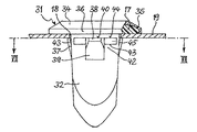
図6及び図7は、挿入部品1に対して変更を施した挿入部品31を示し、以下に詳細に説明される。挿入部品31は、同様に合成材料の止め具であり、例えば金属薄板の壁19の正方形開口部18に挿入可能であり、例えばネジである締結要素を収容するために役立つ。挿入部品31は、細長いスリーブ32と、中心内腔33と、円形の周縁部36及び接着剤のリング17を収容する環状凹部35を備えたフランジ34とを有する。フランジ34に隣接して、スリーブ32は正方形断面形状のスリーブ37を備え、該スリーブ37は、その4つの外側部の各々から外方に突出する係止部38を支持する。係止部38は、スリーブの閉止端に向いた差込傾斜部39と、フランジ34に対向する当接面40とを有する。スリーブ37の内側には、内腔33を取り囲む環状陥凹部41がある。これにより、係止部38を支持する壁部分42の弾性変形性が高められ、その結果、挿入部品を壁19の開口部18に挿入するときに、壁部分42の変形に伴って係止部38を押し込むことができる。
【0028】
係止部38の両側の直近に隣接して、フランジ34に平行な方向で各々スリーブ32の隅部まで延びるリブ様の突起部43がある。突起部43は、フランジ34に向き、係止部38の当接面40の平面内にある境界面44と、スリーブの閉止端に向いた差込傾斜部45とを有する。スリーブ32の外側表面に対して垂直に測定した突起部43の高さは、同様の方法で測定した係止部38の高さよりもかなり低く、係止部38の高さの3分の1から5分の1に過ぎない。
【0029】
挿入部品31を取り付けるとき、突起部43並びに係止部38は、壁19の開口部18を通り抜け、その結果、フランジ34とは反対側にある壁19の側部で挿入部品31の取り付け位置に配置される。突起部43の機能は、挿入部品1の頚部37と壁19の開口部18の縁部との間の環状間隙を付加的に密封することであり、これにより接着剤からなるリング17が溶融したときに、不利な取り付け位置においてもこの環状間隙内に十分な量の接着剤が保持されることになり、従って挿入部品31と壁19との間の信頼性のある密封が達成される。ここで、突起部43の高さは、製造公差に関して挿入部品の外側寸法が最大で開口部寸法が最小の場合でも、挿入部品が取り付け位置の開口部に十分小さな力で押し込むことができ、挿入部品の外側寸法が最小で開口部寸法が最大の場合でも、溶融された接着剤を保持するのに十分な密封が挿入部品と壁との間で達成できるような寸法とされる。突起部43の取り付け及び構造は、図1から図5による実施形態と比較して、挿入部品の取り付け及び緊密な接着を損なうことなく、より大きな製造公差を許容することができるという利点がある。
【0030】
上述の突起部43の構造は非常に有利であるが、本発明はこれに限定されるものではない。或いは突起部43は、図示されたくさび形に代えて、凸形のビード、リブ又は同様のものとして構成することができ、又は密封リップの形態をとることができる。
【図面の簡単な説明】
【図1】止め具として構成された本発明による挿入部品のI−I断面を示す図である。
【図2】図1による挿入部品のII−II断面を示す図である。
【図3】図1による挿入部品のフランジ端部を示す図である。
【図4】接着剤を溶融する前に壁の開口部に挿入された、図1による挿入部品を示す図である。
【図5】接着後の壁の開口部に挿入された挿入部品を示す図である。
【図6】止め具として構成された本発明による挿入部品の別の形態を示す図である。
【図7】図6による挿入部品の、VII−VII線での断面図である。
【符号の説明】
1 挿入部品
4 フランジ
5 凹部
6 周縁部
7 頚部
17 プラスチック体[0001]
BACKGROUND OF THE INVENTION
The present invention is an insertion part for insertion into a wall, in particular an opening in a vehicle body, the neck part passing through the opening part, and the wall around the opening part when the insertion part is arranged in the opening part. Covers the edge and has a recessed portion bounded outward by a raised rim on the lower side toward the neck, and is disposed in a flange disposed on the neck and a recessed portion on the lower side of the flange to be in a fluid state The invention relates to an insert part having a synthetic material capable of holding and holding means for fixing the insert part in the opening of the wall.
[0002]
[Prior art]
An insertion part of the kind described above can be configured as a plug for tight closure of the wall opening of the vehicle body or as a stop intended to accommodate a fastening element, for example a screw.
[0003]
An insert of the above-mentioned type configured as a plug is disclosed in German
[0004]
[0005]
[Problems to be solved by the invention]
The object of the present invention is to create an insert of the type mentioned at the outset, which is able to protect narrow position tolerances and is also suitable for application on inclined walls.
[0006]
[Means for Solving the Problems]
According to the invention, this object is dimensioned such that the plastic body is completely accommodated by the recess on the lower side of the flange, and in the mounting position where the insertion part is fixed to the opening of the wall by the holding means, This is achieved in that the peripheral edge of the flange is pushed into contact with the wall.
[0007]
When the insert according to the invention is inserted into the opening, it is fixed by the holding means until it is finally fixed by the melted plastic and by the flange peripheral edge that is pushed into contact with the wall, It has the advantage that it can be placed in a precisely defined position. Accordingly, it is possible to satisfy a strict requirement for the accuracy of positioning of the inserted part.
[0008]
A further basic advantage is that the arrangement of the insert according to the invention is largely independent of the inclination of the wall in which the opening is installed. The peripheral edge of the flange that is pushed into contact with the wall prevents the molten plastic from leaking out of the flange-side recess before a new setting, even when the wall is in the vertical direction. As a result, a good appearance of adhesion on the flange side of the inserted part is ensured, and alteration of the surface around the flange due to leaked plastic is avoided.
[0009]
Surprisingly, it has further been found that in both the horizontal and vertical directions of the wall, the molten plastic surely enters the annular gap between the edge of the opening and the neck of the insert and seals completely. ing. The insert according to the invention is therefore suitable for tight closure of the wall opening, the edge of the opening being covered with plastic and thus being protected against corrosion. When plastics or adhesives with good wetting action are used for sealing, reliable sealing or bonding is achieved even when the insert is placed overhead.
[0010]
According to a further proposal of the invention, the flange of the insert part is adapted to be elastically deformable transversely with respect to the expansion, and the holding means for fixing the insert part to the opening in the wall comprises: The mounting position can be obtained only by elastic deformation of the flange supported by the wall by the peripheral edge. In this way, the flange forms a spring element that is biased when the insertion part is attached and generates a desired force that presses the peripheral edge into contact. Such a simple means provides a sufficient amount of spring movement to compensate for dimensional deviations during manufacture. Furthermore, the flange can be adapted to deviations in the shape of the wall. According to the present invention, instead of the elastically deformable flange, the holding means can be provided with a spring element that generates a force that presses and contacts the peripheral edge of the flange at the mounting position instead.
[0011]
As a holding means, the insertion part preferably comprises at least two spring-like locking portions, each having a plug ramp and a support surface, and the lock when the plug ramp is inserted into the wall opening. The support surface is suitable for being supported by the wall on the side opposite to the flange after the deformation of the locking portion has returned. According to the present invention, the locking portion can be integrated with the elastically deformable wall portion of the neck portion having no engaging portion. This has the advantage that the neck can be configured as a mounting ring that favors a uniform distribution of adhesive at the adhesive joint formed by the neck and the edge of the opening.
[0012]
According to a further proposal of the invention, the insertion part comprises a shank that extends the neck on the side opposite the flange, the shank having a lumen through the neck and the flange for receiving the fastening element. Including. The free end of the shank can be closed to allow tight closure of the opening.
[0013]
According to the invention, the cross-sectional shape of the neck is a circle or an ellipse or a polygonal shape, in particular a square. In cooperation with the correspondingly shaped opening, the insert is fixed against rotation in the opening, and therefore transmits a counter torque of the wall that acts against the screwing torque, for example when a clamping screw is screwed in. Can do. In order to transmit the greatest possible counter torque between the wall and the insert, according to a further proposal of the invention, the neck has a square cross-sectional shape and projects outwards only on two opposite sides. And a wall supporting the locking portion is provided to be subdivided into an outer spring wall portion and an inner spring wall portion by a longitudinally extending recess. With this configuration, given adequate resilience in the vicinity of the lock, a rigid neck against torsion is created, which is suitable for transmitting a relatively large torque against the wall.
[0014]
It is further advantageous if the insert part is provided with a rib-like projection on the outside of the neck at a distance parallel to the flange, which can be pushed into the opening of the wall when inserting the insert part. It is preferable that the projection has an insertion inclined portion facing away from the flange and a boundary surface facing the flange, and the boundary surface is in the plane of the contact surface of the locking projection. The protrusion seals the annular gap that exists between the neck of the insert and the edge of the opening into which the insert is inserted to such an extent that the molten material of the composite member is retained in the annular gap. Reliable sealing and adhesion of the wall opening is ensured.
[0015]
DETAILED DESCRIPTION OF THE INVENTION
The invention will be described in more detail below with reference to the embodiments represented in the figures by way of illustration.
[0016]
The insert part shown in FIGS. 1 to 3 is, for example, a plastic stopper intended to be inserted into a square opening of a thin metal plate wall on a vehicle body, and by using a screw screwed into the stopper, Can be fixed to the wall. Furthermore, this stopper is for tightly closing the opening to be inserted.
[0017]
The
[0018]
The outer surface of the
[0019]
The
[0020]
The
[0021]
The portion of the
[0022]
The
[0023]
An
[0024]
4 and 5 exemplify the attachment and bonding of the
[0025]
FIG. 5 shows the distribution of the melted adhesive 17 ′ at the end of the flow and curing process initiated by heating. Here, the adhesive 17 ′ completely penetrates the gap between the
[0026]
In addition, since the above-mentioned insertion part generates a sufficient holding force for many applications, the locking
[0027]
6 and 7 show an
[0028]
Immediately adjacent to both sides of the locking
[0029]
When attaching the
[0030]
The structure of the
[Brief description of the drawings]
FIG. 1 shows a cross section II of an insert according to the invention configured as a stop.
2 shows a section II-II of the insert part according to FIG.
3 shows the flange end of the insert according to FIG.
FIG. 4 shows the insert according to FIG. 1 inserted into the opening of the wall before melting the adhesive.
FIG. 5 is a diagram showing an insertion part inserted into the opening of the wall after bonding.
FIG. 6 shows another form of the insert according to the invention configured as a stop.
7 is a cross-sectional view of the insertion part according to FIG. 6, taken along line VII-VII.
[Explanation of symbols]
DESCRIPTION OF
Claims (11)
前記壁の開口部に通されるように構成された頚部と、
前記頚部上に配置されて挿入部品が前記開口部内に配置されたときに前記開口部の周りの壁の縁部を覆うようになっており、前記頚部側に向いた下側に外側が隆起状の周縁によって境界付けられた凹部を備えるフランジと、
前記フランジ下側の前記凹部に配置され、流動状態にすることができるプラスチック体と、
前記壁の開口部に前記挿入部品を固定するための保持手段と、
を有し、
前記プラスチック体(17)が、前記フランジ(4)下側の前記凹部(5)に完全に収められる寸法であり、前記挿入部品(1)が、前記保持手段によって前記壁(19)の開口部(18)に固定される取り付け位置において、前記フランジ(4)の周縁部(6)が前記壁(19)に接触するよう押しつけられるように構成され、
前記頚部(7)が正方形の断面形状を有し、対向する2つの側に外側に突出する係止部(8)によって前記保持部が形成され、前記係止部(8、38)が形成された壁部分が、縦方向に延びる陥凹部(11)によって、外側バネ性壁部分と内側壁部分とに分割されており、
前記頚部(7)内に該頚部(7)の軸方向に延びる内腔(3)が形成されており、
前記内側壁部分が、前記内腔(3)から前記陥凹部(11)に通じる半径方向スリット(15)によって横方向に撓むことができるバネ性舌状部(16)に形成されている
ことを特徴とする挿入部品。 An insertion part for insertion into the opening of the wall,
A neck configured to be passing to the opening of the wall,
Wherein being adapted to cover the edges of the walls around the opening when inserted being arranged on the neck part is disposed in the opening, outside ridged on the lower side facing the neck-side A flange with a recess bounded by the periphery of
A plastic body that is disposed in the recess on the lower side of the flange and can be in a fluid state;
Holding means for fixing the insertion part to the opening of the wall;
I have a,
Said plastic body (17) comprises a flange (4) is dimensioned to be completely contained in the lower side of the recess (5), the insertion part (1) is opening in the wall (19) by said holding means In the mounting position fixed to (18), the peripheral edge (6) of the flange (4) is configured to be pressed against the wall (19) ,
The neck portion (7) has a square cross-sectional shape, and the holding portion is formed by a locking portion (8) protruding outward on two opposing sides, and the locking portion (8, 38) is formed. The wall portion is divided into an outer spring wall portion and an inner wall portion by a recess (11) extending in the longitudinal direction;
A lumen (3) extending in the axial direction of the neck (7) is formed in the neck (7),
The inner wall portion is formed in a springy tongue (16) that can be deflected laterally by a radial slit (15) leading from the lumen (3) to the recess (11). An insertion part characterized by the above.
前記差込傾斜部(9)が、前記頚部(7)を前記壁の前記開口部へ挿入するときに前記係止部(8、38)を半径方向に押し込む働きをし、前記支持面(10、40)が、前記係止部(8、38)の変形が戻った後に、前記フランジ(4)とは反対の側において前記壁に支持されるように構成されたことを特徴とする、請求項1から請求項4までのいずれか1項に記載の挿入部品。 The locking part (8 , 38 ) is constituted by at least two spring-like locking parts (8 , 38 ) each having an insertion inclined part (9 , 39 ) and a support surface (10 , 40 ). And
The insertion inclined portion (9), serves to push the locking portion (8, 38) in the radial direction when inserting the neck (7) into the opening in the wall, said support surface (10 40 ) is configured to be supported by the wall on the opposite side of the flange (4) after the deformation of the locking part (8 , 38 ) has returned. insert part according to any one of claims 1 to claim 4.
前記フランジ(4)を通ることを特徴とする先行する請求項1から請求項8までのいずれか1項に記載の挿入部品。With the flange and shaft portion configured on the opposite side of the extension of the neck (7) (14), for the shaft portion is subjected to the fastening element, said lumen (3 of the neck (7) ) to have a lumen (3) consecutive claim from claim 1 wherein the lumen of the neck (7) (3) the preceding, characterized in that through <br/> the flange (4) 9. The insertion part according to any one of items 1 to 8 .
Applications Claiming Priority (1)
| Application Number | Priority Date | Filing Date | Title |
|---|---|---|---|
| DE2002131274 DE10231274A1 (en) | 2002-07-10 | 2002-07-10 | Plug for car bodywork has shaft which fits through aperture and flange at top with recess on its underside, into which ring of sealant is placed, rim of flange pressing against bodywork when plug is in position |
Publications (2)
| Publication Number | Publication Date |
|---|---|
| JP2004100949A JP2004100949A (en) | 2004-04-02 |
| JP4493294B2 true JP4493294B2 (en) | 2010-06-30 |
Family
ID=29761871
Family Applications (1)
| Application Number | Title | Priority Date | Filing Date |
|---|---|---|---|
| JP2003193300A Expired - Fee Related JP4493294B2 (en) | 2002-07-10 | 2003-07-08 | Inserts for walls, especially body openings |
Country Status (4)
| Country | Link |
|---|---|
| EP (1) | EP1394420B1 (en) |
| JP (1) | JP4493294B2 (en) |
| DE (2) | DE10231274A1 (en) |
| ES (1) | ES2250794T3 (en) |
Families Citing this family (8)
| Publication number | Priority date | Publication date | Assignee | Title |
|---|---|---|---|---|
| ES2306061T3 (en) * | 2005-11-10 | 2008-11-01 | Steelcase Sa | FIXING SYSTEM ON SHEET SHEET. |
| DE202007003635U1 (en) * | 2007-03-12 | 2007-06-21 | Trw Automotive Electronics & Components Gmbh & Co. Kg | Dowel for insertion in opening of wall e.g. car body, has another plastic material which expands in increasing temperature and closes opening tightly in expanded condition with another material component |
| DE102009018395B4 (en) * | 2009-04-22 | 2011-02-10 | Trw Automotive Electronics & Components Gmbh | sealing plug |
| DE102009030040B4 (en) * | 2009-06-23 | 2019-12-12 | Illinois Tool Works Inc. (N.D.Ges.D. Staates Delaware) | Retaining dowel and method for mounting such a retaining dowel |
| JP6067390B2 (en) * | 2013-01-28 | 2017-01-25 | 株式会社ニフコ | Hole plug |
| US10179612B2 (en) * | 2016-09-02 | 2019-01-15 | Ford Global Technologies, Llc | Body aperture plug and body conversion |
| DE102020100419A1 (en) * | 2020-01-10 | 2021-07-15 | Vibracoustic Ag | Component with at least one through opening and an insert part fastened in the through opening |
| DE102021108450A1 (en) | 2021-04-01 | 2022-10-06 | Bayerische Motoren Werke Aktiengesellschaft | Hole closure element for a body component and body component equipped therewith |
Citations (2)
| Publication number | Priority date | Publication date | Assignee | Title |
|---|---|---|---|---|
| US5193961A (en) * | 1992-02-12 | 1993-03-16 | Illinois Tool Works Inc. | Pin and grommet |
| US5738476A (en) * | 1995-05-24 | 1998-04-14 | Maclean-Fogg Company | Fastener |
Family Cites Families (4)
| Publication number | Priority date | Publication date | Assignee | Title |
|---|---|---|---|---|
| GB2067253A (en) * | 1980-01-11 | 1981-07-22 | United Carr Ltd | Aperture plug |
| FR2704212B1 (en) * | 1993-04-23 | 1997-01-03 | Trw Carr France Sa | Synthetic tank cap. |
| FR2731984B1 (en) * | 1995-03-21 | 1997-04-30 | Rapid Sa | PLUG FOR SEALING ANY OPENING AND METHOD FOR MANUFACTURING THE SAME |
| JPH11325012A (en) * | 1998-05-20 | 1999-11-26 | Sds Kk | Rivet |
-
2002
- 2002-07-10 DE DE2002131274 patent/DE10231274A1/en not_active Withdrawn
-
2003
- 2003-07-04 DE DE50301469T patent/DE50301469D1/en not_active Expired - Lifetime
- 2003-07-04 ES ES03015141T patent/ES2250794T3/en not_active Expired - Lifetime
- 2003-07-04 EP EP20030015141 patent/EP1394420B1/en not_active Expired - Fee Related
- 2003-07-08 JP JP2003193300A patent/JP4493294B2/en not_active Expired - Fee Related
Patent Citations (2)
| Publication number | Priority date | Publication date | Assignee | Title |
|---|---|---|---|---|
| US5193961A (en) * | 1992-02-12 | 1993-03-16 | Illinois Tool Works Inc. | Pin and grommet |
| US5738476A (en) * | 1995-05-24 | 1998-04-14 | Maclean-Fogg Company | Fastener |
Also Published As
| Publication number | Publication date |
|---|---|
| ES2250794T3 (en) | 2006-04-16 |
| EP1394420B1 (en) | 2005-10-26 |
| DE50301469D1 (en) | 2005-12-01 |
| DE10231274A1 (en) | 2004-01-22 |
| EP1394420A2 (en) | 2004-03-03 |
| EP1394420A3 (en) | 2004-07-28 |
| JP2004100949A (en) | 2004-04-02 |
Similar Documents
| Publication | Publication Date | Title |
|---|---|---|
| US7048486B2 (en) | Insert part for a wall opening, in particular on a vehicle body | |
| US5217337A (en) | Two-part fastening device for protective strips | |
| US9011061B2 (en) | Holding dowel | |
| US6264393B1 (en) | Connection unit between a support, specifically a body part of a motor vehicle and a plate element | |
| US8572818B2 (en) | Connecting assembly for fastening an add-on element on a carrier | |
| US4646932A (en) | Opening stopper for automotive vehicle bodies | |
| US7997437B2 (en) | Body filler plug | |
| US7802955B2 (en) | Dowel for insertion into an opening of a wall, in particular on a vehicle body | |
| JP4493294B2 (en) | Inserts for walls, especially body openings | |
| JP3464216B2 (en) | Dust cover for disc brake brake cylinder | |
| US7337505B1 (en) | Panel fastener | |
| KR20070026218A (en) | Female part for a fastener, said female part aligning with a hole in a panel | |
| US20050199203A1 (en) | Sealing arrangement and cylinder head cover with such sealing arrangement | |
| US20090113675A1 (en) | Fastener for fastening to a stud | |
| CA2466561A1 (en) | Metal/plastic insert molded sill plate fastener | |
| JPH05248541A (en) | Plug for opening | |
| KR19980041877A (en) | Press Form Bolt | |
| US6287043B1 (en) | Connection between a support and a plate element | |
| KR20110059791A (en) | Fastening device | |
| CN111656023B (en) | Attachment device | |
| EP3444485B1 (en) | Fastener and fastening arrangement | |
| JP3949087B2 (en) | Plastic nut attached to assembly member | |
| JPS6327568B2 (en) | ||
| US4797983A (en) | Connectors for insert moulding in panels | |
| US20200263720A1 (en) | Fastening element for insertion into an opening of a vehicle body part and method for assembly of such a fastening element |
Legal Events
| Date | Code | Title | Description |
|---|---|---|---|
| A621 | Written request for application examination |
Free format text: JAPANESE INTERMEDIATE CODE: A621 Effective date: 20060621 |
|
| A131 | Notification of reasons for refusal |
Free format text: JAPANESE INTERMEDIATE CODE: A131 Effective date: 20091001 |
|
| A601 | Written request for extension of time |
Free format text: JAPANESE INTERMEDIATE CODE: A601 Effective date: 20091225 |
|
| A602 | Written permission of extension of time |
Free format text: JAPANESE INTERMEDIATE CODE: A602 Effective date: 20100105 |
|
| A601 | Written request for extension of time |
Free format text: JAPANESE INTERMEDIATE CODE: A601 Effective date: 20100201 |
|
| A602 | Written permission of extension of time |
Free format text: JAPANESE INTERMEDIATE CODE: A602 Effective date: 20100204 |
|
| A521 | Written amendment |
Free format text: JAPANESE INTERMEDIATE CODE: A523 Effective date: 20100226 |
|
| TRDD | Decision of grant or rejection written | ||
| A01 | Written decision to grant a patent or to grant a registration (utility model) |
Free format text: JAPANESE INTERMEDIATE CODE: A01 Effective date: 20100318 |
|
| A01 | Written decision to grant a patent or to grant a registration (utility model) |
Free format text: JAPANESE INTERMEDIATE CODE: A01 |
|
| A61 | First payment of annual fees (during grant procedure) |
Free format text: JAPANESE INTERMEDIATE CODE: A61 Effective date: 20100406 |
|
| R150 | Certificate of patent or registration of utility model |
Free format text: JAPANESE INTERMEDIATE CODE: R150 |
|
| FPAY | Renewal fee payment (event date is renewal date of database) |
Free format text: PAYMENT UNTIL: 20130416 Year of fee payment: 3 |
|
| LAPS | Cancellation because of no payment of annual fees |