JP4491597B2 - Suspension control method - Google Patents
Suspension control method Download PDFInfo
- Publication number
- JP4491597B2 JP4491597B2 JP2003345552A JP2003345552A JP4491597B2 JP 4491597 B2 JP4491597 B2 JP 4491597B2 JP 2003345552 A JP2003345552 A JP 2003345552A JP 2003345552 A JP2003345552 A JP 2003345552A JP 4491597 B2 JP4491597 B2 JP 4491597B2
- Authority
- JP
- Japan
- Prior art keywords
- vibration
- function
- electromagnetic
- suspension system
- control
- Prior art date
- Legal status (The legal status is an assumption and is not a legal conclusion. Google has not performed a legal analysis and makes no representation as to the accuracy of the status listed.)
- Expired - Lifetime
Links
- 239000000725 suspension Substances 0.000 title claims description 56
- 238000000034 method Methods 0.000 title claims description 29
- 230000033001 locomotion Effects 0.000 claims description 38
- 230000007246 mechanism Effects 0.000 claims description 29
- 230000008929 regeneration Effects 0.000 claims description 19
- 238000011069 regeneration method Methods 0.000 claims description 19
- 230000010355 oscillation Effects 0.000 claims description 5
- 230000002123 temporal effect Effects 0.000 claims description 4
- 238000012544 monitoring process Methods 0.000 claims description 3
- 230000001629 suppression Effects 0.000 claims description 3
- 230000008878 coupling Effects 0.000 claims 2
- 238000010168 coupling process Methods 0.000 claims 2
- 238000005859 coupling reaction Methods 0.000 claims 2
- 238000010586 diagram Methods 0.000 description 25
- 238000005339 levitation Methods 0.000 description 11
- 230000008859 change Effects 0.000 description 10
- 239000002131 composite material Substances 0.000 description 9
- 238000013016 damping Methods 0.000 description 8
- 239000003990 capacitor Substances 0.000 description 6
- XEEYBQQBJWHFJM-UHFFFAOYSA-N Iron Chemical compound [Fe] XEEYBQQBJWHFJM-UHFFFAOYSA-N 0.000 description 4
- 230000000694 effects Effects 0.000 description 4
- 230000009467 reduction Effects 0.000 description 4
- 238000004146 energy storage Methods 0.000 description 3
- 238000005516 engineering process Methods 0.000 description 3
- 230000014509 gene expression Effects 0.000 description 3
- 230000001788 irregular Effects 0.000 description 3
- 230000001172 regenerating effect Effects 0.000 description 3
- 230000002238 attenuated effect Effects 0.000 description 2
- 238000005183 dynamical system Methods 0.000 description 2
- 229910052742 iron Inorganic materials 0.000 description 2
- 230000000704 physical effect Effects 0.000 description 2
- 230000001133 acceleration Effects 0.000 description 1
- 238000013019 agitation Methods 0.000 description 1
- 230000005540 biological transmission Effects 0.000 description 1
- 230000008602 contraction Effects 0.000 description 1
- 230000007423 decrease Effects 0.000 description 1
- 238000001514 detection method Methods 0.000 description 1
- 238000006073 displacement reaction Methods 0.000 description 1
- 238000011156 evaluation Methods 0.000 description 1
- 238000007667 floating Methods 0.000 description 1
- 230000004927 fusion Effects 0.000 description 1
- 230000010354 integration Effects 0.000 description 1
- 238000012986 modification Methods 0.000 description 1
- 230000004048 modification Effects 0.000 description 1
- 238000005096 rolling process Methods 0.000 description 1
- 239000004065 semiconductor Substances 0.000 description 1
- 239000002699 waste material Substances 0.000 description 1
Images


Landscapes
- Vehicle Body Suspensions (AREA)
- Vibration Prevention Devices (AREA)
Description
本発明は、サスペンション系の制御方法に関するものである。 The present invention relates to a suspension system control method.
従来、自動車、鉄道車両等の車両においては、ばねとダンパとを含むサスペンションが広く使用され、車両が道路や軌道を走行する際に発生する振動や動揺を抑制するようになっている。そして、近年においては、電磁デバイスを使用して前記振動や動揺を制御する技術が提案されている。 2. Description of the Related Art Conventionally, suspensions including springs and dampers are widely used in vehicles such as automobiles and railway vehicles, and suppress vibrations and vibrations that occur when the vehicle travels on a road or track. In recent years, a technique for controlling the vibration and shaking using an electromagnetic device has been proposed.
例えば、電磁デバイスとしての電動モータを発電機として利用した電磁ダンパを用いて振動や動揺を制御する技術が提案されている(例えば、特許文献1参照。)。また、可動マスの運動エネルギを回収して利用する船舶等の振動や動揺を制御する技術が提案されている(例えば、特許文献2又は特許文献3参照。)。さらに、電動モータを使用して運動制御を行うサーボ系や電動モータを電気ばねとして活用する能動型減揺装置も提案されている(例えば、特許文献4参照。)。
しかしながら、前記電磁デバイスを使用して振動や動揺を制御する技術にも、いくつかの問題が残っている。例えば、電動モータを発電機として利用した電磁ダンパを用いて振動や動揺を制御する技術においては、パッシブな減衰力のみを制御するので性能に限界がある。また、可動マスの運動エネルギを回収して利用する技術においては、エネルギ収支に着目し、また、センサ機能を有していないので性能に限界がある。さらに、電動モータを使用して運動制御を行うサーボ系においては、振動や動揺に対応することができず、また、電動モータ以外のデバイスも必要となってしまう。さらに、電動モータを電気ばねとして活用する能動型減揺装置においては、エネルギ収支に着目し、また、センサ機能を有していないので性能に限界がある。 However, some problems still remain in the technology for controlling vibration and sway using the electromagnetic device. For example, in a technique for controlling vibration and sway using an electromagnetic damper using an electric motor as a generator, there is a limit in performance because only passive damping force is controlled. Further, in the technique of recovering and using the kinetic energy of the movable mass, attention is paid to the energy balance, and the performance is limited because it does not have a sensor function. Furthermore, in a servo system that performs motion control using an electric motor, it is not possible to cope with vibrations and fluctuations, and devices other than the electric motor are required. Furthermore, in an active vibration reduction device that uses an electric motor as an electric spring, attention is paid to the energy balance, and the performance is limited because it does not have a sensor function.
本発明は、前記従来の問題点を解決して、個別技術を統括又は統合するコンセプトなので理論的に議論することができ、今後新たな方策が生じても対応することができ、一つのデバイスで複数の機能を奏するのでイニシャルコスト及びランニングコストを低減することができ、アクティブ制御を容易に実用化することができ、省エネルギに貢献することができ、ミニチュアダンパのように従来のダンパでは実現困難なサイズのデバイスを実現することができるサスペンション系の制御方法を提供することを目的とする。 Since the present invention solves the above-mentioned conventional problems and integrates or integrates individual technologies, it can be discussed theoretically and can cope with new measures in the future. Since multiple functions are provided, initial cost and running cost can be reduced, active control can be easily put into practical use, energy saving can be achieved, and it is difficult to achieve with conventional dampers like miniature dampers. An object of the present invention is to provide a suspension system control method capable of realizing devices of various sizes.
そのために、本発明のサスペンション系の制御方法においては、サスペンション系における力学系の運動、動揺又は振動を電磁デバイスによって制御する制御方法であって、前記サスペンション系は、被サスペンション体とばね間質量とを結合する並列に配置された第1のばね及び第1の電磁デバイスと、前記ばね間質量と運動変動発生面とを結合する並列に配置された第2のばね及び第2の電磁デバイスとを有し、前記第1及び第2の電磁デバイスの出力を測定することによって、前記第1及び第2の電磁デバイスに作用する力、前記力学系の運動、動揺又は振動のリアルタイムな状態、前記力学系の運動、動揺又は振動の平均的な状態、前記力学系の動揺又は振動を引き起こす外乱、及び、前記力学系の同定を情報として検出し、協調する第1及び第2の電磁デバイスによって前記力学系の運動、動揺又は振動を同時に制御する。 To this end, the suspension system control method of the present invention is a control method for controlling the motion, oscillation or vibration of the dynamic system in the suspension system by an electromagnetic device, wherein the suspension system includes a suspended body, an inter-spring mass, A first spring and a first electromagnetic device arranged in parallel to each other, and a second spring and a second electromagnetic device arranged in parallel to couple the mass between the springs and the motion fluctuation generating surface. And measuring the outputs of the first and second electromagnetic devices, the force acting on the first and second electromagnetic devices, the movement of the dynamic system, the real-time state of shaking or vibration, the dynamics system of movement, the average state of agitation or vibration disturbance causing upset or vibration of the dynamic system, and to detect the identification of the dynamical system as information, coordinated to Motion of the dynamic system by the first and second electromagnetic devices to control sway or vibration at the same time.
本発明の更に他のサスペンション系の制御方法においては、さらに、前記力学系の特性、外乱入力、運動制御目標、動揺又は振動抑制目標、及び、エネルギ収支を関数として、前記パッシブばね機能、パッシブダンパ機能、アクチュエータ機能、センサ機能、エネルギ回生機能又はリンク機構機能の空間的又は時間的分配を行う。 According to still another suspension system control method of the present invention, the passive spring function, the passive damper, and the dynamic system characteristics, disturbance input, motion control target, oscillation or vibration suppression target, and energy balance as functions. Spatial or temporal distribution of functions, actuator functions, sensor functions, energy regeneration functions or link mechanism functions.
本発明の更に他のサスペンション系の制御方法においては、さらに、前記情報は機械システム全体の監視及び制御に使用される。 In still another suspension system control method of the present invention, the information is used for monitoring and control of the entire mechanical system.
本発明の更に他のサスペンション系の制御方法においては、さらに、複数の前記電磁デバイスを連携させて集中統合制御又は自律分散制御を行うことによって、リンク機構として機能させる。 In yet another suspension system control method of the present invention, a plurality of electromagnetic devices are linked to perform centralized integrated control or autonomous distributed control to function as a link mechanism.
本発明によれば、サスペンション系の制御方法においては、サスペンション系における力学系の運動、動揺又は振動を電磁デバイスによって制御する制御方法であって、単数又は協調する複数の電磁デバイスによって、パッシブばね機能、パッシブダンパ機能、アクチュエータ機能、センサ機能、エネルギ回生機能又はリンク機構機能のいずれか又はすべてを融合する。 According to the present invention, the suspension system control method is a control method for controlling the motion, oscillation or vibration of the dynamic system in the suspension system by an electromagnetic device, and a passive spring function is achieved by a single or a plurality of cooperative electromagnetic devices. , Any one or all of the passive damper function, the actuator function, the sensor function, the energy regeneration function and the link mechanism function are fused.
この場合、サスペンション系や電磁デバイスの個別技術を統括又は統合するコンセプトなので理論的に議論することができる。また、新たな方策が生じても対応することができる。さらに、サスペンション系のイニシャルコスト及びランニングコストを低減することができる。さらに、アクティブ制御を容易に実用化することができ、省エネルギに貢献することができ、微小なサイズのデバイスを実現することができる。 In this case, since the concept integrates or integrates individual technologies of suspension systems and electromagnetic devices, it can be discussed theoretically. In addition, it is possible to cope with new measures. Furthermore, the initial cost and running cost of the suspension system can be reduced. Furthermore, active control can be easily put into practical use, can contribute to energy saving, and can realize a device with a minute size.
他のサスペンション系の制御方法においては、さらに、前記力学系の運動、動揺又は振動を同時に同じ電磁デバイスによって制御する。 In another suspension system control method, the dynamic system's motion, fluctuation or vibration is simultaneously controlled by the same electromagnetic device.
この場合、一つの電磁デバイスで制御するので、サスペンション系のイニシャルコスト及びランニングコストを低減することができる。 In this case, since control is performed with one electromagnetic device, the initial cost and running cost of the suspension system can be reduced.
更に他のサスペンション系の制御方法においては、さらに、前記力学系の特性、外乱入力、運動制御目標、動揺又は振動抑制目標、及び、エネルギ収支を関数として、前記パッシブばね機能、パッシブダンパ機能、アクチュエータ機能、センサ機能、エネルギ回生機能又はリンク機構機能の空間的又は時間的分配を行う。 In yet another suspension system control method, the passive spring function, passive damper function, actuator, and function of the dynamic system characteristics, disturbance input, motion control target, oscillation or vibration suppression target, and energy balance as functions. Spatial or temporal distribution of functions, sensor functions, energy regeneration functions or link mechanism functions.
この場合、複数の機能を適切に融合させることができる。 In this case, a plurality of functions can be appropriately fused.
更に他のサスペンション系の制御方法においては、さらに、前記センサ機能は、前記電磁デバイスの出力を測定することによって、前記電磁デバイスに作用する力、前記力学系の運動、動揺又は振動のリアルタイムな状態、前記力学系の運動、動揺又は振動の平均的な状態、前記力学系の動揺又は振動を引き起こす外乱、及び、前記力学系の同定を情報として検出することを含む。 In still another suspension system control method, the sensor function may measure the output of the electromagnetic device, thereby determining the force acting on the electromagnetic device, the dynamic system motion, shaking or vibration in real time. , Detecting an average state of motion, vibration or vibration of the dynamic system, disturbances causing the vibration or vibration of the dynamic system, and identification of the dynamic system as information.
この場合、複合ユニットであっても適切に集中統合制御又は自律分散制御することができる。 In this case, even if it is a composite unit, centralized integrated control or autonomous distributed control can be appropriately performed.
更に他のサスペンション系の制御方法においては、さらに、前記情報は機械システム全体の監視及び制御にも使用される。 In yet another suspension system control method, the information is also used to monitor and control the entire mechanical system.
この場合、機械システム全体の動作を適切に監視し、かつ、制御することができる。 In this case, the operation of the entire mechanical system can be appropriately monitored and controlled.
更に他のサスペンション系の制御方法においては、さらに、複数の前記電磁デバイスを連携させて集中統合制御又は自律分散制御を行うことによって、リンク機構として機能させる。 In still another suspension system control method, a plurality of the electromagnetic devices are linked to perform centralized integrated control or autonomous distributed control to function as a link mechanism.
この場合、例えば、アンチロール・バーやサスペンションに関わる様々なリンク機構と同等の役割を果たすこともできる。 In this case, for example, it can play the same role as various link mechanisms related to the anti-roll bar and the suspension.
以下、本発明の実施の形態について図面を参照しながら詳細に説明する。 Hereinafter, embodiments of the present invention will be described in detail with reference to the drawings.
図1は本発明の第1の実施の形態におけるサスペンション系の制御ユニットの構成を示す概念図である。 FIG. 1 is a conceptual diagram showing a configuration of a suspension system control unit according to the first embodiment of the present invention.
図において、10はサスペンション系の制御ユニットであり、電磁デバイス11、力学系12及び制御手段13を有する。本実施の形態において、サスペンション系は、いかなる種類のものであってもよく、例えば、二輪車、四輪車等の自動車のサスペンション系、鉄道車両のサスペンション系、モノレールのサスペンション系、新交通システムやリニアモータカーの磁気浮上式車両のサスペンション系等であってもよい。また、遊戯施設の乗り物や工場、倉庫内の物流搬送システムの搬送器のサスペンション系であってもよい。さらに、船舶の振動や動揺を抑制する船舶減揺装置であってもよいし、高層ビル等の建築物の振動や動揺を抑制する建築物減揺装置であってもよいし、工場に配設された工作機械等の各種機械の振動や動揺を抑制する制振装置であってもよい。
In the figure,
ここで、前記電磁デバイス11は、例えば、電磁石、電動モータ、リニアモータ等であるが制御可能な電磁デバイスであればいかなるものであってもよい。そして、前記電磁デバイス11は、前記力学系12から回生エネルギが入力されるエネルギ回生機能、ばね力fk+を前記力学系12に対して出力するパッシブばね機能としての正のばね機能、ばね力fk-を前記力学系12に対して出力するパッシブばね機能としての負のばね機能、ダンパ力fc を前記力学系12に対して出力するパッシブダンパ機能としてのダンパ機能、アクチュエータ力fa を前記力学系12に対して出力するアクチュエータ機能、前記力学系12から運動、変動(振動又は動揺)等が入力されるセンサ機能のいずれか又はすべてを備えている。なお、前記センサ機能は、電磁デバイス11の出力を測定することによって、前記電磁デバイス11に作用する力、前記力学系12の運動、動揺又は振動のリアルタイムな状態、前記力学系12の運動、動揺又は振動の平均的な状態、前記力学系12の動揺又は振動を引き起こす外乱、及び、前記力学系12の同定を情報として検出する。本実施の形態において、力学系12の同定とは、該力学系12の運動、動揺、振動等に影響を与える、例えば、乗員及び積載物を含む車両の総質量や車両の慣性モーメントのようなファクターの数値、物理的性質等を判定した結果である。すなわち、前記センサ機能によって、車両の総質量や車両の慣性モーメントのようなファクターの実際の数値、物理的性質等を判定することができ、その結果を情報として検出する。
Here, the
また、前記センサ機能が検出する情報は機械システム全体の監視及び制御にも使用することができる。そして、本実施の形態においては、前記電磁デバイス11によって、前記力学系12の運動、振動又は動揺、すなわち、サスペンション系における力学系の運動、動揺又は振動を同時に制御する。
The information detected by the sensor function can also be used for monitoring and control of the entire mechanical system. In the present embodiment, the
また、前記力学系12は制御手段13による制御の対象であり、例えば、自動車や鉄道車両の車体、船舶の船体、建築物、機械本体等であるが、ばね、ダンパ、台車、車輪等も含むものである。そして、前記力学系12は電磁デバイス11から次の式(1)で表される力f(t)を受ける。
The

さらに、前記制御手段13は、CPU、MPU等の演算手段、磁気ディスク、半導体メモリ等の記憶手段、入出力インターフェイス等を備えるコンピュータであり、例えば、パーソナルコンピュータ、サーバ、ワンチップマイコン等であるが、いかなるものであってもよい。そして、前記制御手段13は制御信号を電磁デバイス11に送信して該電磁デバイス11の動作を通して前記力学系12を制御する。また、前記制御手段13は電磁デバイス11の出力する前記力f(t)を検出する。
Further, the control means 13 is a computer including a calculation means such as a CPU and MPU, a storage means such as a magnetic disk and a semiconductor memory, an input / output interface and the like, for example, a personal computer, a server, a one-chip microcomputer or the like. Anything can be used. The control means 13 transmits a control signal to the
そして、前記制御ユニット10は、モデル推定手段14、外乱推定手段15、検出手段16、切替手段17、外部エネルギ18及びエネルギ貯蓄デバイス19を有する。ここで、該エネルギ貯蓄デバイス19はエネルギを貯蓄するものであればいかなる種類のものであってもよいが、例えば、バッテリ、電気二重層キャパシタ等の蓄電装置であり、前記電磁デバイス11がエネルギ回生機能を備える場合、前記電磁デバイス11が回生した回生エネルギを貯蓄する。
The
また、前記外部エネルギ18はエネルギを供給するものであればいかなる種類のものであってもよいが、例えば、発電機、電力線等である。そして、前記切替手段17は、制御手段13から受信する制御信号に従って前記外部エネルギ18及びエネルギ貯蓄デバイス19からのエネルギを切り替えて電磁デバイス11に供給する。
The
次に、複数の制御ユニット10を複合した複合ユニットについて説明する。まず、複合ユニットを集中統合制御する場合について説明する。
Next, a composite unit in which a plurality of
図2は本発明の第1の実施の形態における複合ユニットを集中統合制御する場合の制御システムの構成を示す概念図である。 FIG. 2 is a conceptual diagram showing a configuration of a control system in the case of performing the centralized integrated control of the composite unit in the first embodiment of the present invention.
ここでは、n個の制御ユニット10−1〜10−nを集中統合制御する場合について説明する。なお、iは、1以上n以下の整数であり、i番目の制御ユニット10−iに関するものであることを示す添字である。この場合、前記制御ユニット10−1〜10−nのそれぞれは集中統合制御用の制御手段21に接続され、該制御手段21によって集中的に、かつ、統合的に制御される。すなわち、前記制御手段21は前記制御ユニット10−1〜10−nのそれぞれの状態を検出して、それぞれを制御する制御信号を送信する。そして、前記制御ユニット10−1〜10−nのそれぞれについて前記電磁デバイス11のパッシブばね機能、パッシブダンパ機能、アクチュエータ機能、センサ機能又はエネルギ回生機能を融合して空間的又は時間的分配を行うために、次の式(3)で表される評価関数Vi が使用される。
Here, a case where the n control units 10-1 to 10-n are subjected to centralized integrated control will be described. Note that i is an integer of 1 to n, and is a subscript indicating that it relates to the i-th control unit 10-i. In this case, each of the control units 10-1 to 10-n is connected to the control means 21 for centralized integration control, and is controlled centrally and integrally by the control means 21. That is, the control means 21 detects the states of the control units 10-1 to 10-n and transmits control signals for controlling the respective states. And for each of the control units 10-1 to 10-n, the passive spring function, the passive damper function, the actuator function, the sensor function or the energy regeneration function of the
しかし、前記制御ユニット10−1〜10−nのそれぞれは、図4に示されるように、相互に通信可能に接続され、それぞれの状態や制御信号を相互に送受信するようになっている。これにより、制御ユニット10−1〜10−nのそれぞれが自律的に制御を行いながら、全体として調和のとれた制御を行うことができる。
However, as shown in FIG. 4, the control units 10-1 to 10-n are communicably connected to each other and transmit / receive their respective states and control signals. Thereby, the control units 10-1 to 10-n can perform harmonious control as a whole while autonomously performing control.
次に、制御ユニット10を磁気浮上式車両のサスペンション系に適用した場合について説明する。
Next, a case where the
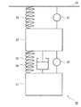
図5は本発明の第1の実施の形態における磁気浮上式車両のサスペンション系の構成を示す概念図、図6は本発明の第1の実施の形態における電磁アクチュエータの構造を示す図、図7は本発明の第1の実施の形態における電磁アクチュエータがパッシブダンパとして機能する場合の等価回路を示す図、図8は本発明の第1の実施の形態における電磁アクチュエータがパッシブダンパとして機能する場合の速度と減衰力との関係を示す図、図9は本発明の第1の実施の形態における電磁アクチュエータがパッシブダンパとして機能する場合のモータの等価回路を示す図、図10は本発明の第1の実施の形態における電磁アクチュエータがパッシブダンパかつエネルギ回生装置として機能する場合の状態量の変化を示す第1の図、図11は本発明の第1の実施の形態における電磁アクチュエータがパッシブダンパかつエネルギ回生装置として機能する場合の状態量の変化を示す第2の図、図12は本発明の第1の実施の形態における電磁アクチュエータがパッシブダンパかつエネルギ回生装置として機能する場合の状態量の変化を示す第3の図、図13は本発明の第1の実施の形態における電磁アクチュエータがパッシブダンパかつエネルギ回生装置として機能する場合の状態量の変化を示す第4の図、図14は本発明の第1の実施の形態における磁気浮上式車両のサスペンション系の動作を示す図である。 FIG. 5 is a conceptual diagram showing the configuration of the suspension system of the magnetically levitated vehicle according to the first embodiment of the present invention. FIG. 6 is a diagram showing the structure of the electromagnetic actuator according to the first embodiment of the present invention. FIG. 8 is a diagram showing an equivalent circuit when the electromagnetic actuator according to the first embodiment of the present invention functions as a passive damper, and FIG. 8 shows a case where the electromagnetic actuator according to the first embodiment of the present invention functions as a passive damper. FIG. 9 is a diagram illustrating a relationship between speed and damping force, FIG. 9 is a diagram illustrating an equivalent circuit of a motor when the electromagnetic actuator according to the first embodiment of the present invention functions as a passive damper, and FIG. 10 is a diagram illustrating the first embodiment of the present invention. FIG. 11 is a first diagram illustrating changes in state quantities when the electromagnetic actuator in the embodiment functions as a passive damper and an energy regeneration device. FIG. 12 is a second diagram showing changes in state quantities when the electromagnetic actuator according to the first embodiment functions as a passive damper and an energy regeneration device, and FIG. 12 shows that the electromagnetic actuator according to the first embodiment of the present invention is passive. FIG. 13 shows a change in state quantity when functioning as a damper and energy regeneration device, and FIG. 13 is a state quantity when the electromagnetic actuator according to the first embodiment of the present invention functions as a passive damper and energy regeneration device. FIG. 14 and FIG. 14 are diagrams showing the operation of the suspension system of the magnetically levitated vehicle according to the first embodiment of the present invention.
図5において、30は新交通システムやリニアモータカーのような磁気浮上式車両、31は該磁気浮上式車両30の車体、32は前記磁気浮上式車両30の台車、33は鉄製のレールから成る軌道、34は永久磁石から成る負のばね、35はコイルスプリング等から成る正のばね、36はオイルダンパ等から成るダンパ、41は電磁デバイス11としての電磁石と図示されない第1の制御手段とから成る第1の制御ユニット、42は後述される電磁デバイス11としての電磁アクチュエータ43と図示されない第2の制御手段とから成る第2の制御ユニットである。
In FIG. 5, 30 is a magnetically levitated vehicle such as a new transportation system or a linear motor car, 31 is a body of the magnetic levitated
そして、前記磁気浮上式車両30は、前記負のばね34及び第1の制御ユニット41の電磁石によって軌道33に吸引された状態で走行する。なお、前記負のばね34のばね定数kは負である。この場合、前記負のばね34としての永久磁石と第1の制御ユニット41の電磁石とを組み合わせた複合磁石の吸引力が浮上総質量と等しくなるように、前記電磁石の吸引力が第1の制御ユニット41における第1の制御手段によって制御される。なお、前記浮上総質量は前記磁気浮上式車両30の質量と搭載される乗員、荷物等の質量とを合計したものである。
The
また、前記車体31と台車32とは前記正のばね35、ダンパ36及び第2の制御ユニット42の電磁アクチュエータ43によって結合されている。この場合、前記正のばね35は、コイルスプリング、エアスプリング等の通常のばねであればいかなる種類のものであってもよく、また、ダンパ36も、オイルダンパ、フリクションダンパ等の通常の、いわゆる、パッシブダンパであればいかなる種類のものであってもよい。
The
この場合、前記磁気浮上式車両30における力学系12は、車体31、台車32、軌道33、負のばね34、正のばね35及びダンパ36から成り、制御手段13及び電磁デバイス11は第1の制御ユニット41及び第2の制御ユニット42から成る。
In this case, the
そして、前記第2の制御ユニット42の電磁アクチュエータ43は、図6に示されるように、第1ケーシング45、該第1ケーシング45に対して長手方向(図6における左右方向)に移動可能な第2ケーシング46、前記第1ケーシング45内に取り付けられたDCモータ47、該DCモータ47の回転軸に接続されたボールねじ軸48、及び、前記第2ケーシング46に取り付けられ前記ボールねじ軸48に螺(ら)合するボールナット49を有する。
As shown in FIG. 6, the
この場合、前記第1ケーシング45及び第2ケーシング46が相対的に外力によって移動させられると、前記ボールナット49がボールねじ軸48に対して矢印Aで示されるように直線運動を行う。ここで、前記ボールナット49は、第2ケーシング46に取り付けられて回転不能となっているので、前記ボールねじ軸48が矢印Bで示されるように回転させられる。すなわち、前記ボールねじ軸48とボールナット49とによって構成されるボールねじ機構によって、矢印Aで示される直線運動が矢印Bで示される回転運動に変換される。そして、前記ボールねじ軸48に接続されたDCモータ47の回転軸が回転させられると、前記DCモータ47によって発電が行われる。これにより、矢印Bで示される回転運動の運動エネルギが電気エネルギに変換されて消費されるので、前記矢印Aで示される直線運動の運動エネルギも消費される。すなわち、前記DCモータ47によって発電が行われることにより、前記第1ケーシング45と第2ケーシング46との相対的な直線運動が減衰させられる。そのため、前記第1ケーシング45及び第2ケーシング46の一方を車体31に取り付け、他方を台車32に取り付けることによって、前記車体31と台車32との相対的な運動を減衰させることができる。
In this case, when the
ここで、前記電磁アクチュエータ43がパッシブダンパとして機能する場合の等価回路が図7に示されている。図7において、51は等価回路におけるモータであり抵抗が0である。また、52はDCモータ47の内部抵抗であり、53は外部抵抗である。そして、前記内部抵抗52と外部抵抗53との合計としての総抵抗値を変化させることによって、パッシブダンパとして機能する前記電磁アクチュエータ43の減衰係数を変化させることができる。この場合、総抵抗値が大きくなるほど減衰係数が小さくなる。そのため、前記電磁アクチュエータ43がパッシブダンパとして機能する場合、第2の制御ユニット42における第2の制御手段は前記外部抵抗53の値を制御するようになっている。
Here, an equivalent circuit when the
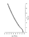
そして、図6に示されるような電磁アクチュエータ43を実際に試作して実験を行ったところ、電磁アクチュエータ43がパッシブダンパとして機能する場合の速度と減衰力との関係は図8に示されるようになることが分かった。なお、図8に示される例では、外部抵抗53の値は2〔Ω〕である。この場合、電磁アクチュエータ43は、速度に比例した減衰力を発生することが分かる。
Then, when the
なお、φ2 /Rは電磁アクチュエータ43の減衰係数に等しい。
Note that φ 2 / R is equal to the attenuation coefficient of the
したがって、前記等価回路を流れる電流Iを検出することによって、前記力fを検出することができる。なお、電圧の値は抵抗値と電流値とを乗じたものなので、前記内部抵抗52又は外部抵抗53の両端の電圧を計測することによって電流Iを求めて、前記力fを検出することもできる。
Therefore, the force f can be detected by detecting the current I flowing through the equivalent circuit. Since the voltage value is obtained by multiplying the resistance value and the current value, the force f can be detected by obtaining the current I by measuring the voltage across the
また、電磁アクチュエータ43の発生する力は、DCモータ47の出力、動摩擦力、DCモータ47の内部慣性による慣性力の和であることから、電磁アクチュエータに加えられた荷重Fは、次の式(15)によって推定される。
Further, since the force generated by the
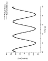
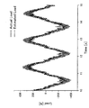
そして、前記式(12)〜(15)を使用して、リアルタイムで電磁アクチュエータ43がパッシブダンパとして機能する場合の状態量の推定を行いった。ここで、推定された状態量と実際に計測された状態量との比較を図10〜13に示す。なお、図10はストローク速度の時間的変化を、図11はストロークの時間的変化を、図12はストローク加速度の時間的変化を、図13は荷重の時間的変化をそれぞれ示している。
And using said Formula (12)-(15), the state quantity in case the
そして、図14に示されるように、前記構成の磁気浮上式車両30を軌道33に沿って走行させると、前記磁気浮上式車両30の車体31は、軌跡37で示されるように、滑らかに移動する。この場合、前記軌道33は軌道不整部分33aを備えるので、該軌道不整部分33aを通過する際に磁気浮上式車両30に対して外乱が与えられるが、第1の制御ユニット41及び第2の制御ユニット42が適切に動作することによって、車体31は前記外乱に応答しない。すなわち、第1の制御ユニット41及び第2の制御ユニット42による防振制御によって、前記車体31には軌道不整部分33aによる振動が伝達されることがない。
Then, as shown in FIG. 14, when the magnetically levitated
なお、前記軌道33の曲線部33bにおいて、前記車体31は、軌跡37で示されるように、前記軌道33の変化に遅れることなく追従する。すなわち、第1の制御ユニット41及び第2の制御ユニット42による運動制御によって、前記車体31は軌道33に適切に追従することができる。なお、前記曲線部33bは、前記軌道33が大きく湾曲して平面曲線又は縦曲線を形成する箇所であり、前記平面曲線又は縦曲線に追従して前記車体31が左右又は上下に変位する箇所である。
In the
このように、本実施の形態における制御方法においては、サスペンション系における力学系12の運動、動揺又は振動を電磁デバイス11によって制御するようになっている。この場合、該電磁デバイス11は、前記力学系12から回生エネルギが入力されるエネルギ回生機能、ばね力fk+を前記力学系12に対して出力するパッシブばね機能としての正のばね機能、ばね力fk-を前記力学系12に対して出力するパッシブばね機能としての負のばね機能、ダンパ力fc を前記力学系12に対して出力するパッシブダンパ機能としてのダンパ機能、アクチュエータ力fa を前記力学系12に対して出力するアクチュエータ機能、前記力学系12から運動、振動又は動揺が入力されるセンサ機能のいずれか又はすべてを備えている。そのため、一つのデバイスで五つの機能を奏するので、サスペンション系のイニシャルコスト及びランニングコストを低減することができる。
As described above, in the control method according to the present embodiment, the
また、前記電磁デバイス11によって、前記力学系12の運動、振動又は動揺、すなわち、サスペンション系の力学的な運動、動揺又は振動を同時に制御するようになっている。そのため、一つの電磁デバイス11で五つの機能を融合することができる。
Further, the
さらに、複数の制御ユニット10を複合した複合ユニットを集中統合制御したり、自律分散制御したりすることができ、複数の電磁デバイス11が協調して機能融合を高度化することができる。さらに、電磁デバイス11がセンサ機能を備えることもでき、負のばね機能を備えることもできる。
Furthermore, a composite unit obtained by combining a plurality of
次に、本発明の第2の実施の形態について説明する。なお、第1の実施の形態と同じ構造を有するものについては、同じ符号を付与することによって、その説明を省略する。また、前記第1の実施の形態と同じ動作及び効果についても、その説明を省略する。 Next, a second embodiment of the present invention will be described. In addition, about the thing which has the same structure as 1st Embodiment, the description is abbreviate | omitted by providing the same code | symbol. The description of the same operations and effects as those of the first embodiment is also omitted.
図15は本発明の第2の実施の形態における電磁アクチュエータが発生する力と電流との関係を示す図である。なお、図15において、横軸には電流値(A)を、縦軸には力(N)を採ってある。 FIG. 15 is a diagram showing the relationship between the force and current generated by the electromagnetic actuator according to the second embodiment of the present invention. In FIG. 15, the horizontal axis represents current value (A) and the vertical axis represents force (N).
本実施の形態においては、前記電磁デバイス11をアクチュエータとして機能させた場合に発生する力と供給電流との関係を、実験結果に基づいて説明する。第1の実施の形態において説明した電磁デバイス11としての電磁アクチュエータ43にアクチュエータ機能を発揮させる場合、DCモータ47に供給される電流Iと電磁アクチュエータ43が発生する力fとの関係は、DCモータ47のモータ係数をφとすると、次の式(16)で表される。なお、前記モータ係数はモータに固有の定数である。
f=φ・I・・・式(16)
該式(16)から、DCモータ47に電流Iを供給すると電磁アクチュエータ43が力fを発生し、アクチュエータ機能を発揮することが分かる。なお、前記式(16)は、第1の実施の形態において説明した電磁アクチュエータ43がセンサ機能を発揮する場合の前記式(6)と同じものになる。
In the present embodiment, the relationship between the force generated when the
f = φ · I Formula (16)
From the equation (16), it can be seen that when the current I is supplied to the
そして、図6に示されるような電磁アクチュエータ43を実際に試作して実験を行ったところ、DCモータ47に供給される電流Iと電磁アクチュエータ43が発生する力fとの関係は図15に示されるようになることが分かった。この場合、電磁アクチュエータ43は、DCモータ47に供給される電流Iに比例した力fを発生することが分かる。
Then, when the
次に、本発明の第3の実施の形態について説明する。なお、第1及び第2の実施の形態と同じ構造を有するものについては、同じ符号を付与することによって、その説明を省略する。また、前記第1及び第2の実施の形態と同じ動作及び効果についても、その説明を省略する。 Next, a third embodiment of the present invention will be described. In addition, about the thing which has the same structure as 1st and 2nd embodiment, the description is abbreviate | omitted by providing the same code | symbol. The description of the same operations and effects as those of the first and second embodiments is also omitted.
本実施の形態においては、前記電磁デバイス11をばねとして機能させた場合について説明する。この場合、第1の実施の形態において説明した電磁デバイス11としての電磁アクチュエータ43が有するセンサ機能によって前記電磁アクチュエータ43のストロークを測定し、さらに、第2の実施の形態において説明した電磁アクチュエータ43が有するアクチュエータ機能によって、前記ストロークに比例した復元力を発生させることによって、ばね機能を達成するようになっている。なお、前記電磁アクチュエータ43のストロークは、図6に示される矢印Aで示される方向に移動する第1ケーシング45及び第2ケーシング46の相対的な距離である。
In the present embodiment, the case where the
ここで、前記電磁アクチュエータ43のストロークをzとすると、ストロークzは、DCモータ47に供給される電流I及びDCモータ47の端子電圧vを測定することによって、次の式(17)で表される。なお、前記端子電圧vは図7に示される等価回路における内部抵抗52の両端の電圧であり、該内部抵抗52の抵抗値をrとする。
Here, when the stroke of the
ところで、ばねとは伸び、すなわち、変位に比例した復元力を発生させるものであるので、ばねが発生する力fk は、ばね定数をkとすると、次の式(18)で表される。
By the way, since the spring generates elongation, that is, a restoring force proportional to the displacement, the force f k generated by the spring is expressed by the following equation (18), where the spring constant is k.
そのため、前記電磁アクチュエータ43をばねとして機能させる場合、前記式(17)及び(18)から、次の式(19)で表される力fを前記電磁アクチュエータ43が発生すればよいことになる。
Therefore, when the
また、前記電磁アクチュエータ43は、第2の実施の形態において説明したように、DCモータ47に供給される電流Iに比例した力fを発生する。すなわち、前記電磁アクチュエータ43が発生する力fは、前記式(16)で表される。そのため、該式(16)及び(19)から、DCモータ47に供給される電流Iは、次の式(20)で表される。
The
このように、該式(20)で表されるような電流IをDCモータ47に供給することによって、電磁デバイス11をばねとして機能させることができる。
Thus, by supplying the current I as represented by the formula (20) to the
次に、本発明の第4の実施の形態について説明する。なお、第1〜第3の実施の形態と同じ構造を有するものについては、同じ符号を付与することによって、その説明を省略する。また、前記第1〜第3の実施の形態と同じ動作及び効果についても、その説明を省略する。 Next, a fourth embodiment of the present invention will be described. In addition, about the thing which has the same structure as 1st-3rd embodiment, the description is abbreviate | omitted by providing the same code | symbol. The description of the same operations and effects as those of the first to third embodiments is also omitted.
図16は本発明の第4の実施の形態における電磁デバイスを使用したリンク機構の構成を示す概念図、図17は本発明の第4の実施の形態における電磁デバイスをリンク機構に使用した場合の電気的接続を示す図、図18は本発明の第4の実施の形態における等価なリンク機構を示す図である。 FIG. 16 is a conceptual diagram showing the configuration of a link mechanism using an electromagnetic device according to the fourth embodiment of the present invention, and FIG. 17 is a diagram when the electromagnetic device according to the fourth embodiment of the present invention is used for a link mechanism. FIG. 18 is a diagram showing an electrical connection, and FIG. 18 is a diagram showing an equivalent link mechanism in the fourth embodiment of the present invention.
本実施の形態においては、電磁デバイス11としての電磁アクチュエータ43を使用したリンク機構について説明する。この場合、前記電磁アクチュエータ43が有するパッシブダンパ機能及びアクチュエータ機能を使用し、複数の電磁アクチュエータ43を連携させて集中統合制御又は自律分散制御を行うことによってリンク機構として機能させることができる。
In the present embodiment, a link mechanism using an
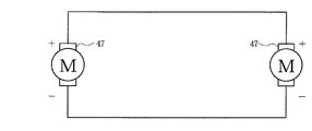
図16に示されるリンク機構55においては、二つの電磁アクチュエータ43が中心点59に関して点対称となるように配設されている。図16における右側の電磁アクチュエータ43は、上端が右側の固定部材56に取り付けられ、下端が右側の可動部材57に取り付けられている。該右側の可動部材57は、矢印Cで示されるように、下方に移動可能となっている。また、図16における左側の電磁アクチュエータ43は、下端が左側の固定部材56に取り付けられ、上端が左側の可動部材57に取り付けられている。該左側の可動部材57は、矢印Cで示されるように、上方に移動可能となっている。そして、前記リンク機構55において、左右の電磁アクチュエータ43のDCモータ47の端子は、図17に示されるように、プラスの端子同士及びマイナスの端子同士が互いに接続されるように、電気的に接続されている。
In the link mechanism 55 shown in FIG. 16, the two
これにより、一方の電磁アクチュエータ43が伸縮することによって発生したDCモータ47の端子電圧が、他方の電磁アクチュエータ43のDCモータ47に印加されるので、他方の電磁アクチュエータ43が一方の電磁アクチュエータ43と同様に伸縮することになる。この場合、左右の可動部材57を図16に示されるような連結線58で連結すると、該連結線58は前記中心点59を中心にして回転する。すなわち、一方の可動部材57が、図16に示されるように、矢印Cで示される方向に位置57’にまで移動すると、他方の可動部材57も矢印Cで示される方向に位置57’にまで移動する。この場合、前記連結線58は、前記中心点59を中心にして位置58’まで回転する。
As a result, the terminal voltage of the
図18には、前記リンク機構55と等価なリンク機構60が示されている。該リンク機構60においては、固定部材63に取り付けられた支柱62に、リンク部材61が中心軸61aを中心として回転可能に取り付けられている。そして、前記リンク部材61の両端には、可動部材64がそれぞれ取り付けられている。そのため、一方の可動部材64が矢印Dで示されるように移動すると、他方の可動部材64も、同様に、矢印Dで示されるように移動する。この場合、前記リンク機構55の可動部材57、連結線58及び中心点59は、等価なリンク機構60の可動部材64、リンク部材61及び中心軸61aにそれぞれ対応する。
FIG. 18 shows a
次に、電磁アクチュエータ43から成るリンク機構をアンチロール・リンク機構として使用する場合について説明する。
Next, the case where the link mechanism comprising the
図19は本発明の第4の実施の形態における電磁デバイスを使用したアンチロール・リンク機構を磁気浮上式車両のサスペンション系に適用した場合の構成を示す概念図である。 FIG. 19 is a conceptual diagram showing a configuration when an anti-roll link mechanism using an electromagnetic device according to a fourth embodiment of the present invention is applied to a suspension system of a magnetically levitated vehicle.
この場合、図19に示されるように、二つの電磁アクチュエータ43が新交通システムやリニアモータカーのような磁気浮上式車両70の左右に、それぞれ、配設される。なお、図19において、71は該磁気浮上式車両70の車体、72は前記磁気浮上式車両70の台車、73は鉄製のレールから成る軌道、74は永久磁石から成る負のばね、75はコイルスプリング等から成る正のばねである。
In this case, as shown in FIG. 1 9, two of the
ここで、左右の電磁アクチュエータ43のDCモータ47の端子を、図17に示されるように、プラスの端子同士及びマイナスの端子同士が互いに接続されるようにすると、左右の電磁アクチュエータ43が同位相で伸縮する場合にはDCモータ47に電流が流れないが、左右の電磁アクチュエータ43が逆位相で伸縮する場合にはDCモータ47に電流が流れてパッシブダンパとして機能するようになる。すなわち、左右の電磁アクチュエータ43がともに伸長したり、ともに収縮したりする場合にはDCモータ47に電流が流れないが、一方の電磁アクチュエータ43が伸長すると他方の電磁アクチュエータ43が収縮する場合にはDCモータ47に電流が流れ、左右の電磁アクチュエータ43がパッシブダンパとして機能するようになる。したがって、左右の電磁アクチュエータ43はロール方向のパッシブダンパとして機能するので、車体71がロールすることを防止するアンチロール・バーと同等の役割を果たすことができる。
Here, if the terminals of the
次に、本発明の第5の実施の形態について説明する。なお、第1〜第4の実施の形態と同じ構造を有するものについては、同じ符号を付与することによって、その説明を省略する。また、前記第1〜第4の実施の形態と同じ動作及び効果についても、その説明を省略する。 Next, a fifth embodiment of the present invention will be described. In addition, about the thing which has the same structure as 1st-4th embodiment, the description is abbreviate | omitted by providing the same code | symbol. The description of the same operations and effects as those in the first to fourth embodiments is also omitted.
図20は本発明の第5の実施の形態における電磁デバイスをエネルギ回生に使用した場合の電気的接続を示す図、図21は本発明の第5の実施の形態における電磁アクチュエータをエネルギ回生に使用した場合のキャパシタ電圧の時刻歴を示す図である。 FIG. 20 is a diagram showing the electrical connection when the electromagnetic device according to the fifth embodiment of the present invention is used for energy regeneration, and FIG. 21 shows the use of the electromagnetic actuator according to the fifth embodiment of the present invention for energy regeneration. It is a figure which shows the time history of the capacitor voltage at the time of doing.
本実施の形態においては、電磁デバイス11としての電磁アクチュエータ43を使用してエネルギを回生する場合について説明する。この場合、図20に示されるように、電磁アクチュエータ43のDCモータ47の端子をキャパシタ78に接続し、前記DCモータ47が回生した電気エネルギをキャパシタ78に蓄電する。
In the present embodiment, a case where energy is regenerated using the
そして、図6に示されるような電磁アクチュエータ43を実際に試作して実験を行ったところ、電磁アクチュエータ43がエネルギを回生する場合におけるキャパシタ78の電圧の時刻歴は図21に示されるようになることが分かった。
Then, when the
なお、前記第1〜第5の実施の形態においては、前記制御方法を新交通システムやリニアモータカーのような磁気浮上式車両のサスペンション系に適用した場合について具体的に説明したが、二輪車、四輪車等の自動車のサスペンション系、鉄道車両のサスペンション系、モノレールのサスペンション系、遊戯施設の乗り物や工場や倉庫内の物流搬送システムの搬送器のサスペンション系等のいかなるサスペンション系にも本実施の形態における制御方法を適用することができることは明らかである。さらに、前記制御方法を適用するサスペンション系は、船舶の振動や動揺を抑制する船舶減揺装置であってもよいし、高層ビル等の建築物の振動や動揺を抑制する建築物減揺装置であってもよいし、工場に配設された工作機械等の各種機械の振動や動揺を抑制する制振装置であってもよい。 In the first to fifth embodiments, the case where the control method is applied to a suspension system of a magnetically levitated vehicle such as a new traffic system or a linear motor car has been specifically described. This embodiment can be applied to any suspension system such as a suspension system for automobiles such as wheeled vehicles, a suspension system for railway vehicles, a suspension system for monorails, a vehicle for amusement facilities, and a suspension system for a transporter in a factory or warehouse. It is clear that the control method in can be applied. Furthermore, the suspension system to which the control method is applied may be a ship vibration reduction device that suppresses vibrations and vibrations of the ship, or a building vibration reduction device that suppresses vibrations and vibrations of buildings such as high-rise buildings. It may also be a vibration damping device that suppresses vibrations and fluctuations of various machines such as machine tools installed in a factory.
また、本発明は前記実施の形態に限定されるものではなく、本発明の趣旨に基づいて種々変形させることが可能であり、それらを本発明の範囲から排除するものではない。 The present invention is not limited to the above-described embodiment, and various modifications can be made based on the spirit of the present invention, and they are not excluded from the scope of the present invention.
11 電磁デバイス
12 力学系
43 電磁アクチュエータ
55、60 リンク機構
11
Claims (4)
(b)前記サスペンション系は、被サスペンション体とばね間質量とを結合する並列に配置された第1のばね及び第1の電磁デバイスと、前記ばね間質量と運動変動発生面とを結合する並列に配置された第2のばね及び第2の電磁デバイスとを有し、
(c)前記第1及び第2の電磁デバイスの出力を測定することによって、前記第1及び第2の電磁デバイスに作用する力、前記力学系の運動、動揺又は振動のリアルタイムな状態、前記力学系の運動、動揺又は振動の平均的な状態、前記力学系の動揺又は振動を引き起こす外乱、及び、前記力学系の同定を情報として検出し、
(d)協調する第1及び第2の電磁デバイスによって前記力学系の運動、動揺又は振動を同時に制御することを特徴とするサスペンション系の制御方法。 (A) A control method for controlling movement, fluctuation or vibration of a dynamic system in a suspension system by an electromagnetic device,
(B) The suspension system includes a first spring and a first electromagnetic device arranged in parallel for coupling the suspension body and the mass between the springs, and a parallel coupling between the mass between the springs and the motion fluctuation generation surface. A second spring and a second electromagnetic device disposed on
(C) by measuring the outputs of the first and second electromagnetic devices, the force acting on the first and second electromagnetic devices, the motion of the dynamic system, the real-time state of shaking or vibration, the dynamics Detecting the motion of the system, the average state of the vibration or vibration, the disturbance causing the vibration or vibration of the dynamic system, and the identification of the dynamic system as information,
(D) A suspension system control method comprising simultaneously controlling the motion, oscillation or vibration of the dynamic system by means of the first and second electromagnetic devices that cooperate.
Priority Applications (1)
| Application Number | Priority Date | Filing Date | Title |
|---|---|---|---|
| JP2003345552A JP4491597B2 (en) | 2002-10-03 | 2003-10-03 | Suspension control method |
Applications Claiming Priority (2)
| Application Number | Priority Date | Filing Date | Title |
|---|---|---|---|
| JP2002290776 | 2002-10-03 | ||
| JP2003345552A JP4491597B2 (en) | 2002-10-03 | 2003-10-03 | Suspension control method |
Publications (3)
| Publication Number | Publication Date |
|---|---|
| JP2004144299A JP2004144299A (en) | 2004-05-20 |
| JP2004144299A5 JP2004144299A5 (en) | 2006-11-30 |
| JP4491597B2 true JP4491597B2 (en) | 2010-06-30 |
Family
ID=32473402
Family Applications (1)
| Application Number | Title | Priority Date | Filing Date |
|---|---|---|---|
| JP2003345552A Expired - Lifetime JP4491597B2 (en) | 2002-10-03 | 2003-10-03 | Suspension control method |
Country Status (1)
| Country | Link |
|---|---|
| JP (1) | JP4491597B2 (en) |
Families Citing this family (3)
| Publication number | Priority date | Publication date | Assignee | Title |
|---|---|---|---|---|
| JP4753376B2 (en) * | 2006-12-12 | 2011-08-24 | 国立大学法人 東京大学 | Electromagnetic device system and control method thereof |
| JP5695991B2 (en) * | 2011-07-07 | 2015-04-08 | 学校法人五島育英会 | Wave power generator |
| JP5779685B2 (en) * | 2014-04-07 | 2015-09-16 | 本田技研工業株式会社 | Electric damper device for vehicle |
-
2003
- 2003-10-03 JP JP2003345552A patent/JP4491597B2/en not_active Expired - Lifetime
Also Published As
| Publication number | Publication date |
|---|---|
| JP2004144299A (en) | 2004-05-20 |
Similar Documents
| Publication | Publication Date | Title |
|---|---|---|
| Kim et al. | Design and control of levitation and guidance systems for a semi-high-speed maglev train | |
| Zhou et al. | Review of coupled vibration problems in EMS maglev vehicles | |
| KR100299466B1 (en) | Controllers for controlling moving objects, control methods and sensors for use in those controllers | |
| US9616770B2 (en) | Electric vehicle drive apparatus, method of driving an electric vehicle, and program | |
| CN101296811A (en) | Suspension system for vehicle | |
| JP6453750B2 (en) | Orbit control device | |
| Ohishi et al. | Adhesion control of electric motor coach based on force control using disturbance observer | |
| Han et al. | Dynamic modeling and simulation of EMS maglev vehicle to evaluate the levitation stability and operational safety over an elastic segmented switch track | |
| JP4647527B2 (en) | Vibration model device for articulated vehicle of magnetic levitation railway | |
| JP6550654B2 (en) | Orbit control device | |
| JP2008222112A (en) | Energy regenerating damper device and energy regenerating damper system | |
| Katz et al. | Performance of magnetic suspensions for high speed vehicles operating over flexible guideways | |
| JP4491597B2 (en) | Suspension control method | |
| Wei et al. | Distributed fault detection observer for rail vehicle suspension systems | |
| Han | A study on the dynamic modeling of a magnetic levitation vehicle | |
| CN109094599B (en) | Electromagnetic transverse active vibration reduction system and control method and device thereof | |
| CN114544204B (en) | Superconductive maglev train testing platform and disturbance resistance method | |
| Liu et al. | A vibration energy harvester for freight train track self-powered application | |
| JP2005065411A (en) | Flywheel type electric power storage device for mounting on vehicle, and system for controlling body of vehicle | |
| JP4929442B2 (en) | Vehicle motion control apparatus and automobile | |
| Buth et al. | Dynamic analysis of vehicle-guideway interaction in a maglev cargo transportation system | |
| JP3733929B2 (en) | Motor and vehicle motion control device | |
| Mei et al. | Research on Fault Modeling and Fault Diagnosis of Maglev Suspension System | |
| JP4753377B2 (en) | Electromagnetic device system and control method thereof | |
| Mei et al. | Development of self-contained active suspensions for railway vehicles |
Legal Events
| Date | Code | Title | Description |
|---|---|---|---|
| A521 | Request for written amendment filed |
Free format text: JAPANESE INTERMEDIATE CODE: A523 Effective date: 20040204 |
|
| A521 | Request for written amendment filed |
Free format text: JAPANESE INTERMEDIATE CODE: A523 Effective date: 20060929 |
|
| A621 | Written request for application examination |
Free format text: JAPANESE INTERMEDIATE CODE: A621 Effective date: 20060929 |
|
| A977 | Report on retrieval |
Free format text: JAPANESE INTERMEDIATE CODE: A971007 Effective date: 20090302 |
|
| A131 | Notification of reasons for refusal |
Free format text: JAPANESE INTERMEDIATE CODE: A131 Effective date: 20090331 |
|
| A521 | Request for written amendment filed |
Free format text: JAPANESE INTERMEDIATE CODE: A523 Effective date: 20090601 |
|
| TRDD | Decision of grant or rejection written | ||
| A01 | Written decision to grant a patent or to grant a registration (utility model) |
Free format text: JAPANESE INTERMEDIATE CODE: A01 Effective date: 20100309 |
|
| A01 | Written decision to grant a patent or to grant a registration (utility model) |
Free format text: JAPANESE INTERMEDIATE CODE: A01 |
|
| A61 | First payment of annual fees (during grant procedure) |
Free format text: JAPANESE INTERMEDIATE CODE: A61 Effective date: 20100311 |
|
| R150 | Certificate of patent or registration of utility model |
Ref document number: 4491597 Country of ref document: JP Free format text: JAPANESE INTERMEDIATE CODE: R150 Free format text: JAPANESE INTERMEDIATE CODE: R150 |
|
| FPAY | Renewal fee payment (event date is renewal date of database) |
Free format text: PAYMENT UNTIL: 20130416 Year of fee payment: 3 |
|
| FPAY | Renewal fee payment (event date is renewal date of database) |
Free format text: PAYMENT UNTIL: 20130416 Year of fee payment: 3 |
|
| S533 | Written request for registration of change of name |
Free format text: JAPANESE INTERMEDIATE CODE: R313533 |
|
| FPAY | Renewal fee payment (event date is renewal date of database) |
Free format text: PAYMENT UNTIL: 20130416 Year of fee payment: 3 |
|
| R350 | Written notification of registration of transfer |
Free format text: JAPANESE INTERMEDIATE CODE: R350 |
|
| FPAY | Renewal fee payment (event date is renewal date of database) |
Free format text: PAYMENT UNTIL: 20130416 Year of fee payment: 3 |
|
| FPAY | Renewal fee payment (event date is renewal date of database) |
Free format text: PAYMENT UNTIL: 20140416 Year of fee payment: 4 |
|
| R250 | Receipt of annual fees |
Free format text: JAPANESE INTERMEDIATE CODE: R250 |
|
| R250 | Receipt of annual fees |
Free format text: JAPANESE INTERMEDIATE CODE: R250 |
|
| R250 | Receipt of annual fees |
Free format text: JAPANESE INTERMEDIATE CODE: R250 |
|
| R250 | Receipt of annual fees |
Free format text: JAPANESE INTERMEDIATE CODE: R250 |
|
| R250 | Receipt of annual fees |
Free format text: JAPANESE INTERMEDIATE CODE: R250 |
|
| R250 | Receipt of annual fees |
Free format text: JAPANESE INTERMEDIATE CODE: R250 |
|
| R250 | Receipt of annual fees |
Free format text: JAPANESE INTERMEDIATE CODE: R250 |
|
| R250 | Receipt of annual fees |
Free format text: JAPANESE INTERMEDIATE CODE: R250 |
|
| R250 | Receipt of annual fees |
Free format text: JAPANESE INTERMEDIATE CODE: R250 |
|
| R250 | Receipt of annual fees |
Free format text: JAPANESE INTERMEDIATE CODE: R250 |
|
| R250 | Receipt of annual fees |
Free format text: JAPANESE INTERMEDIATE CODE: R250 |
|
| EXPY | Cancellation because of completion of term |