JP4489455B2 - Disk control device and control method of disk control device - Google Patents
Disk control device and control method of disk control device Download PDFInfo
- Publication number
- JP4489455B2 JP4489455B2 JP2004038169A JP2004038169A JP4489455B2 JP 4489455 B2 JP4489455 B2 JP 4489455B2 JP 2004038169 A JP2004038169 A JP 2004038169A JP 2004038169 A JP2004038169 A JP 2004038169A JP 4489455 B2 JP4489455 B2 JP 4489455B2
- Authority
- JP
- Japan
- Prior art keywords
- data
- storage device
- logical volume
- split
- identifier
- Prior art date
- Legal status (The legal status is an assumption and is not a legal conclusion. Google has not performed a legal analysis and makes no representation as to the accuracy of the status listed.)
- Expired - Fee Related
Links
Images


Classifications
-
- G—PHYSICS
- G06—COMPUTING; CALCULATING OR COUNTING
- G06F—ELECTRIC DIGITAL DATA PROCESSING
- G06F11/00—Error detection; Error correction; Monitoring
- G06F11/07—Responding to the occurrence of a fault, e.g. fault tolerance
- G06F11/14—Error detection or correction of the data by redundancy in operation
- G06F11/1402—Saving, restoring, recovering or retrying
- G06F11/1446—Point-in-time backing up or restoration of persistent data
- G06F11/1458—Management of the backup or restore process
- G06F11/1461—Backup scheduling policy
-
- G—PHYSICS
- G06—COMPUTING; CALCULATING OR COUNTING
- G06F—ELECTRIC DIGITAL DATA PROCESSING
- G06F11/00—Error detection; Error correction; Monitoring
- G06F11/07—Responding to the occurrence of a fault, e.g. fault tolerance
- G06F11/14—Error detection or correction of the data by redundancy in operation
- G06F11/1402—Saving, restoring, recovering or retrying
- G06F11/1446—Point-in-time backing up or restoration of persistent data
- G06F11/1448—Management of the data involved in backup or backup restore
- G06F11/1451—Management of the data involved in backup or backup restore by selection of backup contents
-
- G—PHYSICS
- G06—COMPUTING; CALCULATING OR COUNTING
- G06F—ELECTRIC DIGITAL DATA PROCESSING
- G06F11/00—Error detection; Error correction; Monitoring
- G06F11/07—Responding to the occurrence of a fault, e.g. fault tolerance
- G06F11/14—Error detection or correction of the data by redundancy in operation
- G06F11/1402—Saving, restoring, recovering or retrying
- G06F11/1446—Point-in-time backing up or restoration of persistent data
- G06F11/1456—Hardware arrangements for backup
-
- G—PHYSICS
- G06—COMPUTING; CALCULATING OR COUNTING
- G06F—ELECTRIC DIGITAL DATA PROCESSING
- G06F11/00—Error detection; Error correction; Monitoring
- G06F11/07—Responding to the occurrence of a fault, e.g. fault tolerance
- G06F11/14—Error detection or correction of the data by redundancy in operation
- G06F11/1402—Saving, restoring, recovering or retrying
- G06F11/1471—Saving, restoring, recovering or retrying involving logging of persistent data for recovery
-
- G—PHYSICS
- G06—COMPUTING; CALCULATING OR COUNTING
- G06F—ELECTRIC DIGITAL DATA PROCESSING
- G06F11/00—Error detection; Error correction; Monitoring
- G06F11/07—Responding to the occurrence of a fault, e.g. fault tolerance
- G06F11/14—Error detection or correction of the data by redundancy in operation
- G06F11/1402—Saving, restoring, recovering or retrying
- G06F11/1446—Point-in-time backing up or restoration of persistent data
- G06F11/1458—Management of the backup or restore process
- G06F11/1469—Backup restoration techniques
-
- G—PHYSICS
- G06—COMPUTING; CALCULATING OR COUNTING
- G06F—ELECTRIC DIGITAL DATA PROCESSING
- G06F2201/00—Indexing scheme relating to error detection, to error correction, and to monitoring
- G06F2201/80—Database-specific techniques
Abstract
Description
本発明は、ディスク制御装置及びディスク制御装置の制御方法に関する。 The present invention relates to a disk control device and a control method for the disk control device .
近年、インターネットを利用した商品販売システムなど、24時間無停止で運用される情報処理システムが増加している。このような情報処理システムで用いられるデータは、データ量の増加や耐障害性の向上の要求に伴い、ディスクアレイ装置上のデータベースに格納されることが多い。無停止で運用される情報処理システムにおいては、データベースの更新処理を停止することなく、データベースに格納されているデータをバックアップする必要がある。そこで、ディスクアレイ装置内にバックアップ用のレプリカボリュームを設け、データベースに格納されているデータをバックアップ用のレプリカボリュームにも記憶しておく方法が用いられている。レプリカボリュームへのデータの書き込みを停止し、レプリカボリュームに記憶されているデータを磁気テープ等の外部記憶媒体にコピーすることにより、データベースのある時点のバックアップを取得することができる。 In recent years, there has been an increase in information processing systems that operate 24 hours a day, such as product sales systems using the Internet. Data used in such an information processing system is often stored in a database on a disk array device in accordance with a request for an increase in data amount or improvement in fault tolerance. In an information processing system that is operated without interruption, it is necessary to back up data stored in the database without stopping the database update process. Therefore, a method is used in which a backup replica volume is provided in the disk array device, and the data stored in the database is also stored in the backup replica volume. By stopping the writing of data to the replica volume and copying the data stored in the replica volume to an external storage medium such as a magnetic tape, a backup at a certain point in the database can be obtained.
特許文献1においては、レプリカボリュームへのデータの書き込みを停止している間にデータベースに書き込まれたデータを、バックアップの完了後にレプリカボリュームに書き込むリシンク処理が開示されている。
リシンク処理を実行している最中は、レプリカボリュームの内容は保証されない。そこで、1つのデータベースに対して2つのレプリカボリュームを設け、リシンク処理を2つのレプリカボリュームで交互に行っている場合もある。この場合、データベースを格納するデータ領域にハードウェア障害が発生すると、いずれか一方のレプリカボリュームとデータベースのREDOログとを用いてデータベースを復旧することが可能である。
While the resync process is being executed, the contents of the replica volume are not guaranteed. Therefore, there are cases where two replica volumes are provided for one database, and resync processing is performed alternately on the two replica volumes. In this case, if a hardware failure occurs in the data area for storing the database, it is possible to recover the database using either one of the replica volumes and the redo log of the database.
データベースの運用においては、上記のハードウェア障害の他に、ソフトウェアの不具合やユーザの操作ミス等によりデータベースに不正なデータが書き込まれる場合がある。このような障害をソフトウェア障害と呼んでいる。ソフトウェア障害が発生すると、磁気テープ等に保存されているある時点のデータを復元し、復元されたデータとREDOログとを用いてデータベースを復旧する必要がある。磁気テープ等からのデータ復元には相当の時間を要するため、システムの停止時間が長くなってしまう。 In database operation, in addition to the above hardware failures, illegal data may be written to the database due to software malfunctions or user operation errors. Such a failure is called a software failure. When a software failure occurs, it is necessary to restore data at a certain point stored on a magnetic tape or the like, and restore the database using the restored data and the REDO log. Since a considerable amount of time is required to restore data from a magnetic tape or the like, the system stop time becomes long.
そこで、ソフトウェア障害が発生した際に、磁気テープ等の外部記憶媒体からデータを復元することなく、ディスクアレイ装置内のデータを用いて迅速にデータベースを復旧することが求められている。ここで、前述した2つのレプリカボリュームを用いる場合、データベースを格納するボリュームの3倍の記憶容量が必要となり、ディスクアレイ装置を導入する際の費用が増大する。 Therefore, when a software failure occurs, it is required to quickly restore the database using data in the disk array device without restoring data from an external storage medium such as a magnetic tape. Here, when the two replica volumes described above are used, a storage capacity three times that of the volume storing the database is required, and the cost for introducing the disk array device increases.
そのため、ハードウェア障害及びソフトウェア障害に対して、データベースをバックアップするために必要となる記憶容量を低減させることが求められている。
また、リシンク処理においては、レプリカボリュームに書き込むためのデータをデータベースから読み出す必要がある。そのため、リシンク処理中は外部からデータベースへのアクセス性能が劣化するという問題がある。そこで、外部からデータベースへのアクセス性能を低下させずに、データベースを迅速に復旧することが求められている。
また、データベースの迅速な復旧とは別に、データベースの更新処理を停止することなく、万が一に備えてデータベースのある時点のバックアップを取得することが求められている。
Therefore, it is required to reduce the storage capacity necessary for backing up the database against hardware failure and software failure.
In the resync process, data to be written to the replica volume needs to be read from the database. Therefore, there is a problem that the access performance to the database from the outside deteriorates during the resync process. Therefore, it is required to quickly restore the database without degrading the access performance to the database from the outside.
In addition to the rapid recovery of the database, it is required to obtain a backup of the database at a certain point in case of an emergency without stopping the database update process.
本発明は上記課題を鑑みてなされたものであり、ディスク制御装置及びディスク制御装置の制御方法を提供することを主たる目的とする。 The present invention has been made in view of the above problems, and has as its main object to provide a disk control device and a control method for the disk control device .
上記課題を解決するために、本発明のうち主たる発明では、情報処理装置と通信可能に接続され、一又は複数の論理ボリュームが形成されている第一の記憶デバイスと、一又は複数の論理ボリュームが形成されている第二の記憶デバイスと、第三の記憶デバイスとに対するデータの書き込みまたは読み出しを行うディスク制御装置であって、 前記第一の記憶デバイスの前記論理ボリュームの識別子である主論理ボリュームの識別子と前記第二の記憶デバイスの前記論理ボリュームの識別子である副論理ボリュームの識別子とが対応付けられたペア管理テーブルと、任意の値に設定された検出時間と、を記憶するメモリと、計時機構と、前記情報処理装置から前記第一の記憶デバイスの前記論理ボリュームに対するデータの書き込み要求と前記データとを受信する書き込み要求受信部と、前記書き込み要求を受信すると前記データを前記第一の記憶デバイスの前記論理ボリュームに書き込む第一の書き込み部と、前記データが書き込まれている前記第一の記憶デバイスの前記論理ボリュームの識別子、当該論理ボリューム内の前記データが格納されている位置情報、前記計時機構より取得される現在時刻である更新時刻、及び前記データで構成されるジャーナルデータを前記第三の記憶デバイスに書き込むジャーナル書き込み部と、前記第三の記憶デバイスに記憶されている複数の前記ジャーナルデータのそれぞれの前記更新時刻と前記メモリに記憶されている前記検出時間とを参照し、前記計時機構より取得される現在時刻と前記更新時刻との差が前記検出時間を超えている前記ジャーナルデータを前記複数のジャーナルデータの中から選択し、選択された前記ジャーナルデータの前記更新時刻が早い順に前記ジャーナルデータの前記論理ボリュームの識別子と前記位置情報と前記データとを参照し、当該論理ボリュームの識別子が前記主論理ボリュームの識別子である前記副論理ボリュームの識別子を前記ペア管理テーブルから取得し、当該データを前記第二の記憶デバイスの当該副論理ボリュームの識別子で示される前記論理ボリュームの当該位置情報で示される場所に書き込む第二の書き込み部と、前記情報処理装置から前記第二の記憶デバイスへの前記データの書き込みを中断するスプリット指示命令を受信するスプリット指示命令受信部と、前記情報処理装置から前記第二の記憶デバイスへの前記データの書き込みを再開するスプリット解除命令を受信するスプリット解除命令受信部と、前記スプリット指示命令を受信すると前記スプリット指示命令を受信したことを示すデータと前記計時機構より取得される現在時刻であるスプリット時刻とで構成されるスプリット指示データを前記第三の記憶デバイスに書き込むスプリット指示記憶部と、前記スプリット解除命令を受信すると前記スプリット解除命令を受信したことを示すデータであるスプリット解除データを前記第三の記憶デバイスに書き込むスプリット解除記憶部とを有し、前記第二の書き込み部は前記第三の記憶デバイスに前記スプリット指示データが記憶され、かつ、前記スプリット解除データが記憶されていない場合は、前記スプリット指示データの前記スプリット時刻を参照し、前記更新時刻が当該スプリット時刻より遅い前記ジャーナルデータの前記データを前記第二の記憶デバイスに書き込まないこととする。 In order to solve the above-described problem, in the main invention of the present invention, a first storage device that is communicably connected to an information processing apparatus and forms one or more logical volumes, and one or more logical volumes Is a disk control device for writing or reading data to or from the second storage device and the third storage device, wherein the main logical volume is the identifier of the logical volume of the first storage device A pair management table in which an identifier of the second storage device is associated with an identifier of a secondary logical volume that is an identifier of the logical volume of the second storage device, and a detection time set to an arbitrary value, A timing mechanism; a data write request from the information processing apparatus to the logical volume of the first storage device; and A write request receiving unit that receives data, a first writing unit that writes the data to the logical volume of the first storage device when the write request is received, and the first in which the data is written The identifier of the logical volume of the storage device, the location information where the data in the logical volume is stored, the update time that is the current time obtained from the timekeeping mechanism, and the journal data composed of the data Referring to the journal writing unit for writing to the third storage device, the update time of each of the plurality of journal data stored in the third storage device, and the detection time stored in the memory, The difference between the current time acquired from the timing mechanism and the update time exceeds the detection time. The final data is selected from the plurality of journal data, and the logical volume identifier, the position information, and the data of the journal data are referred to in order from the earliest update time of the selected journal data. The identifier of the secondary logical volume whose identifier is the identifier of the primary logical volume is acquired from the pair management table, and the data of the logical volume indicated by the identifier of the secondary logical volume of the second storage device is obtained. A second writing unit for writing in a location indicated by position information; a split instruction command receiving unit for receiving a split instruction command for interrupting writing of the data from the information processing apparatus to the second storage device; and the information Writing the data from the processing device to the second storage device A split cancel command receiving unit that receives a split cancel command for resuming the data, a data indicating that the split command is received when the split command is received, and a split time that is a current time obtained from the timing mechanism; A split instruction storage unit that writes split instruction data to the third storage device, and split release data that is data indicating that the split release instruction is received when the split release instruction is received. A split release storage unit for writing to a storage device, and the second writing unit stores the split instruction data in the third storage device and the split release data is not stored, With reference to the split time of the split instruction data, It is assumed that the data of the journal data whose update time is later than the split time is not written to the second storage device .
ディスク制御装置及びディスク制御装置の制御方法を提供することができる。 A disk control device and a control method of the disk control device can be provided.
==ディスクアレイ装置==
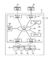
本実施の形態におけるディスクアレイ装置の第一の形態を図1に示す。ディスクアレイ装置10は、ディスク制御装置110と複数のハードディスクドライブ120とを備えている。ディスクアレイ装置10は情報処理装置20と通信手段により接続されている。通信手段は、例えば、LAN(Local Area Network)やSAN(Storage Area Network)、iSCSI(Internet Small Computer System Interface)、ESCON(Enterprise Systems Connection)(登録商標)、FICON(Fibre Connection)(登録商標)などである。
== Disk array device ==
FIG. 1 shows a first embodiment of the disk array device in the present embodiment. The
情報処理装置20は、CPU(Central Processing Unit)やメモリを備えるコンピュータであり、パーソナルコンピュータやワークステーション、メインフレームなどのコンピュータである。情報処理装置20は、結合された複数台のコンピュータで構成されることもある。情報処理装置20ではオペレーティングシステムが動作している。オペレーティングシステム上ではアプリケーションソフトウェアが動作している。アプリケーションソフトウェアは、例えば、銀行の自動預金預け払いシステムや航空機の座席予約システムの機能を提供する。
The
ディスク制御装置110はディスクアレイ装置10全体の制御を司る。ディスク制御装置110は、情報処理装置20から受信したコマンドに従ってハードディスクドライブ120に対する制御を行う。例えば情報処理装置20からデータの入出力要求を受信して、ハードディスクドライブ120に記憶されているデータの入出力のための処理を行う。
The
ディスク制御装置110は、チャネル制御部131、ディスク制御部132、共有メモリ133、キャッシュメモリ134、これらの間を通信可能に接続するクロスバスイッチなどで構成されるスイッチング制御部135、及び管理端末136などを備えて構成される。また、ディスク制御装置110を構成する各部131〜136は耐障害性を高めるために冗長化されてもよい。
The
キャッシュメモリ134は、主としてチャネル制御部131とディスク制御部132との間で授受されるデータを一時的に記憶するために用いられる。例えばチャネル制御部131が情報処理装置20から受信したデータ入出力コマンドが書き込みコマンドである場合には、チャネル制御部131は情報処理装置20から受信した書き込みデータをキャッシュメモリ134に書き込む。またディスク制御部132はキャッシュメモリ134から書き込みデータを読み出してハードディスクドライブ120に書き込む。なお、キャッシュメモリ134は不揮発とすることもできる。この場合、チャネル制御部131が情報処理装置20から受信したデータがキャッシュメモリ134に書き込まれた段階で、情報処理装置20に書込完了通知を送信することとしてもよい。
The
ディスク制御部132は、チャネル制御部131により共有メモリ133に書き込まれたデータ入出力要求を読み出してそのデータ入出力要求に設定されているコマンド(例えば、SCSI(Small Computer System Interface)規格のコマンド)に従ってハードディスクドライブ120にデータの書き込みや読み出しなどの処理を実行する。ディスク制御部132はハードディスクドライブ120から読み出したデータをキャッシュメモリ134に書き込む。またデータの書き込み完了通知や読み出し完了通知などをチャネル制御部131に送信する。ディスク制御部132は、ハードディスクドライブ120をいわゆるRAID(Redundant Array of Inexpensive Disks)方式に規定されるRAIDレベル(例えば、0,1,5)で制御する機能を備えることもある。
The
ハードディスクドライブ120により提供される記憶領域は、この記憶領域上に論理的に設定されるボリュームである論理ボリューム121を単位として管理されている。ハードディスクドライブ120へのデータの書き込みや読み出しは、論理ボリュームに付与される識別子を指定して行なうことができる。
The storage area provided by the
管理端末136はディスクアレイ装置10を保守・管理するためのコンピュータである。チャネル制御部131やディスク制御部132において実行されるソフトウェアやパラメータの変更は、管理端末136からの指示により行われる。管理端末136はディスクアレイ装置10に内蔵される形態とすることもできるし、別体とすることもできる。
The
共有メモリ133はチャネル制御部131、ディスク制御部132、及び管理端末136からアクセスが可能である。チャネル制御部131とディスク制御部132との間におけるデータ入出力要求コマンドの受け渡しに利用される他、ディスクアレイ装置10の管理情報等が記憶される。
The shared
図2はチャネル制御部131の構成を示すブロック図である。チャネル制御部131は、インタフェース部201、メモリ202、CPU203、NVRAM(Nonvolatile Random-Access Memory)204、コネクタ205を備え、これらが一枚もしくは複数枚の回路基板に一体的なユニットとして形成されている。
FIG. 2 is a block diagram showing the configuration of the
インタフェース部201は、情報処理装置20との間で通信を行うためのインタフェースを備えている。通信を行うためのインタフェースとは、例えば、ファイバチャネルに対応したコネクタやイーサネット(登録商標)に対応したコネクタなどである。
The
コネクタ205は、チャネル制御部131をディスクアレイ装置10に接続するためのコネクタである。コネクタ205がディスクアレイ装置10側のコネクタと嵌合することにより、チャネル制御部131が形成される基板はディスクアレイ装置10と電気的に接続される。チャネル制御部131はコネクタ205を介してスイッチング制御部135に接続され、共有メモリ133、キャッシュメモリ134、ディスク制御部132などにアクセスすることができる。
The
CPU203はチャネル制御部131の全体の制御を司る。CPU203はメモリ202やNVRAM203に格納されている各種プログラムを実行することによりチャネル制御部131の機能を実現する。NVRAM203は各種プログラムや設定データなどを格納する不揮発性のメモリである。NVRAM203に記憶される各種プログラムや設定データなどの内容は管理端末136からの指示により書き換えを行うことができる。
The
図3はディスク制御部132の構成を示すブロック図である。ディスク制御部132は、インタフェース部301、メモリ302、CPU303、NVRAM304、コネクタ305を備え、これらが一枚もしくは複数枚の回路基板に一体的なユニットとして形成されている。
FIG. 3 is a block diagram showing the configuration of the
インタフェース部301は、ハードディスクドライブ120との間で通信を行うためのインタフェースを備えている。通信を行うためのインタフェースとは、例えば、SCSI規約に従うコネクタやファイバチャネル規約に従うコネクタなどである。
The
コネクタ305は、ディスク制御部132をディスクアレイ装置10に接続するためのコネクタである。コネクタ305がディスクアレイ装置10側のコネクタと嵌合することにより、ディスク制御部132が形成される基板はディスクアレイ装置10と電気的に接続される。ディスク制御部132はコネクタ305を介してスイッチング制御部135に接続され、共有メモリ133、キャッシュメモリ134、チャネル制御部131などにアクセスすることができる。
The
CPU303はディスク制御部132の全体の制御を司る。CPU303はメモリ302やNVRAM303に格納されている各種プログラムを実行することによりディスク制御部132の機能を実現する。NVRAM303は各種プログラムや設定データなどを格納する不揮発性のメモリである。NVRAM303に記憶される各種プログラムや設定データなどの内容は管理端末136からの指示により書き換えを行うことができる。
The
次に、本実施の形態におけるディスクアレイ装置の第二の形態を図4に示す。第二の形態においては、ディスク制御装置110の構成が図1に示した第一の形態と異なる。ディスク制御装置110は、CPU141、メモリ142、ホストインタフェース143、ディスクインタフェース144、キャッシュメモリ145、データコントローラ146を備えている。
Next, FIG. 4 shows a second form of the disk array device in the present embodiment. In the second embodiment, the configuration of the
CPU141はディスクアレイ装置10の全体の制御を司る。CPU141はメモリ142に格納されているプログラムを実行することによりハードディスクドライブ120の管理やブロックアクセス要求の解釈など様々な機能を実現することができる。
The
ホストインタフェース143は情報処理装置20との間で通信を行うインタフェースである。ホストインタフェース143はファイバチャネルプロトコルに従ってブロックアクセス要求を受け付ける機能を備える。
ディスクインタフェース144はハードディスクドライブ120との間でデータのやり取りを行うインタフェースである。ディスクインタフェース144はハードディスクドライブ120を制御するコマンドなどを規定するプロトコルに従ってハードディスクドライブ120に対するデータ入出力要求を送信する機能を備える。ディスクインタフェース144は、SCSIやファイバチャネルなどのプロトコルに従ってハードディスクドライブ120に対してデータの書き込みや読み出しのコマンドを送信することができる。
The
The
キャッシュメモリ145は、ホストインタフェース143とディスクインタフェース144との間で授受されるデータが記憶されるメモリである。
データコントローラ146は、CPU141の制御によりホストインタフェース143とキャッシュメモリ145との間、あるいはキャッシュメモリ145とディスクインタフェース144との間でのデータ転送を行うものである。データコントローラ146は、例えば、特定用途向けICにロジックを形成する回路とすることができる。
The
The
情報処理装置20がハードディスクドライブ120に対するデータの書き込み要求をディスクアレイ装置10に送信すると、ディスクアレイ装置10では、ホストインタフェース143が書き込み要求を受け付け、データコントローラ146が書き込み要求に付随する書き込みデータをキャッシュメモリ145に転送する。書き込みデータがキャッシュメモリ145に転送されると、データコントローラ146がキャッシュメモリ145からディスクインタフェース144に書き込みデータを読み出し、ディスクインタフェース144がハードディスクドライブ120に対して書き込みを指示するコマンドを送信する。
When the
なお、キャッシュメモリ145は不揮発とすることもできる。この場合、ホストインタフェース143が情報処理装置20から受信したデータがキャッシュメモリ145に書き込まれた段階で、CPU141が情報処理装置20に書込完了通知を送信することとしてもよい。
Note that the
以上、ディスクアレイ装置10の構成について説明した。なお、ディスクアレイ装置10は、以上に説明した構成のもの以外にも、例えば、NFS(Network File System)などのプロトコルにより情報処理装置20からファイル名指定によるデータ入出力要求を受け付けるように構成されたNAS(Network Attached Storage)として機能するものなどであってもよい。
The configuration of the
==データベースの運用形態==
次に、本実施の形態における、ディスクアレイ装置10に構築されたデータベースの運用形態について説明する。
図5は、クライアント端末30、データベースサーバ40、ディスクアレイ装置10で構成されるデータベースシステムを示す図である。データベースサーバ40は、図1および図4における情報処理装置20に相当する。
図6は、クライアント端末30の構成を示すブロック図である。クライアント端末30は、CPU601、メモリ602、記憶装置603、ポート604、記録媒体読取装置605、入力装置606、出力装置607を備える。
== Database operation mode ==
Next, an operation mode of the database constructed in the
FIG. 5 is a diagram showing a database system including the
FIG. 6 is a block diagram illustrating a configuration of the
CPU601はクライアント端末30の全体の制御を司るもので、メモリ602や記憶装置603に格納されたプログラムを実行することにより各種機能を実現する。記憶装置603は、例えばハードディスクドライブなどの記憶装置である。記録媒体読取装置605は、記録媒体608に記録されているプログラムやデータを読み取るための装置である。読み取られたプログラムやデータはメモリ602や記憶装置603に格納される。記録媒体608としてはフレキシブルディスクやCD−ROM、半導体メモリ等を用いることができる。記録媒体読取装置605はクライアント端末30に内蔵されている形態とすることもできるし、外付されている形態とすることもできる。入力装置606はオペレータ等によるクライアント装置30へのデータ入力等のために用いられる。入力装置606としては例えばキーボードやマウス等が用いられる。出力装置607は情報を外部に出力するための装置である。出力装置607としては例えばディスプレイやプリンタ等が用いられる。ポート604はデータベースサーバ40と通信を行うための装置である。
The
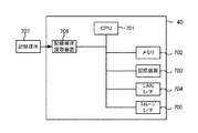
図7は、データベースサーバ40の構成を示すブロック図である。データベースサーバ40は、CPU701、メモリ702、記憶装置703、LANインタフェース704、ストレージインタフェース705、記録媒体読取装置706を備える。
FIG. 7 is a block diagram showing the configuration of the
CPU701はデータベースサーバ40の全体の制御を司るもので、メモリ702や記憶装置703に格納されたプログラムを実行することにより各種機能を実現する。記憶装置703は、例えばハードディスクドライブなどの記憶装置である。記録媒体読取装置706は、記録媒体707に記録されているプログラムやデータを読み取るための装置である。読み取られたプログラムやデータはメモリ702や記憶装置703に格納される。記録媒体707としてはフレキシブルディスクやCD−ROM、半導体メモリ等を用いることができる。記録媒体読取装置706はデータベースサーバ40に内蔵されている形態とすることもできるし、外付されている形態とすることもできる。
The
LANインタフェース704はクライアント端末30とLAN等の通信手段により通信を行うためのインタフェースである。また、ストレージインタフェース705は、ストレージ装置10とSANやLAN等の通信手段により通信を行うためのインタフェースである。
The
図5に示すように、ディスクアレイ装置10には、データ領域501とREDOログ領域502とが設けられている。データ領域501とREDOログ502領域は、一つ又は複数のハードディスクドライブ120により構成される記憶領域である。クライアント端末30は、データ領域501に格納されているテーブル503,504の更新要求をデータベースサーバ40に送信する。データベースサーバ40には、データベースバッファ505とREDOログバッファ506とが設けられている。データベースバッファ505とREDOログバッファ506は後述する記憶装置703に記憶されている。データベースバッファ505に格納されているデータは、データ領域501に格納されているデータのキャッシュデータとして使用される。これにより、データベースサーバ40はディスクアレイ装置10へのアクセスを行うことなく、クライアント端末30からのテーブル更新要求に応答することができ、クライアント端末30への応答時間を短縮することが可能となる。同様に、REDOログバッファ506に格納されているデータは、REDOログ領域502に格納されているデータのキャッシュデータとして使用される。
As shown in FIG. 5, the
データベースの更新処理においては、複数のテーブルの更新を保証することが要求される。例えば、銀行の預金口座間における振込の場合、振込元の口座を管理するテーブルに記憶されている預金残高を減額し、振込先の口座を管理するテーブルに記憶されている預金残高を増額する必要がある。つまり、振込元のテーブルの更新と振込先のテーブルの更新とが完了しないと、更新処理が正しく行われたことにならない。データベースサーバ40は、このように複数のテーブルの更新を保証する機能を備えている。クライアント端末30は、複数のテーブルの更新処理を実行した後に、これら複数のテーブルの更新処理の保証を要求するためのコミット要求をデータベースサーバ40に送信する。データベースサーバ40は、これら複数のテーブルの更新処理の途中で何らかの障害が発生した場合は、これら複数のテーブルを更新前の状態に戻すことができる。
In the database update process, it is required to guarantee the update of a plurality of tables. For example, in the case of a transfer between bank deposit accounts, it is necessary to reduce the deposit balance stored in the table that manages the transfer source account and increase the deposit balance stored in the table that manages the transfer destination account There is. In other words, the update process is not performed correctly unless the transfer source table and the transfer destination table are updated. The
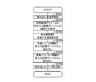
図8は、データ領域501のテーブル503,504を更新する処理を示すフローチャートである。クライアント端末30は、データベースサーバ40にテーブル503の更新要求を送信する(S801)。更新要求にはテーブル503における更新位置と更新データとが含まれている。更新要求を受信すると、データベースサーバ40は更新位置情報をもとに更新データをデータベースバッファ505に格納する(S802)。そして、データベースサーバ40は、更新位置情報と更新データとをREDOログバッファ506に格納し(S803)、クライアント端末30に更新完了通知を送信する(S804)。続いて、クライアント端末30はテーブル504の更新要求をデータベースサーバ40に送信する。データベースサーバ40は、同様にデータベースバッファ505及びREDOログバッファ506の更新を行い(S806,S807)、更新完了通知をクライアント端末30に送信する(S808)。テーブル504の更新完了通知を受信すると、クライアント端末30は、当該更新処理のコミット要求をデータベースサーバ40に送信する(S809)。
コミット要求を受信すると、データベースサーバ40は、REDOログバッファ506に格納されているテーブル503及びテーブル504の更新における更新位置情報と更新データとをREDOログ領域502に書き込む更新要求をディスクアレイ装置10に送信する(S810)。ディスクアレイ装置10はREDOログ領域502に更新位置情報と更新データとを格納し(S811)、更新完了通知をデータベースサーバ40に送信する(S812)。データベースサーバ40は、ディスクアレイ装置10からREDOログ領域502の更新完了通知を受信すると、コミット完了通知をクライアント端末30に送信する(S813)。クライアント端末30は、データベースサーバ40からコミット完了通知を受信し(S814)、テーブル503,504の更新が保証されたことを認識する。
FIG. 8 is a flowchart showing processing for updating the tables 503 and 504 in the
Upon receiving the commit request, the
データベースバッファ505に格納された更新データは、クライアント端末30との間で行われる一連の処理(S801〜S814)とは非同期に、ディスクアレイ装置10のデータ領域501に格納される。まず、データベースサーバ40は、データ領域501から更新前のデータの読み出す要求をディスクアレイ装置10に送信する(S851)。ディスクアレイ装置10は、更新前のデータをデータ領域501から読み出し、データベースサーバ40に送信する(S852)。データベースサーバ40は、更新前のデータと更新位置情報とをREDOログ領域502に書き込む要求をディスクアレイ装置10に送信する(S853)。ディスクアレイ装置10は、更新前のデータと更新位置情報とをREDOログ領域502に格納し(S854)、更新完了通知をデータベースサーバ40に送信する(S855)。データベースサーバ40は、REDOログ領域502の更新完了通知を受信すると、データベースバッファ505に格納されている更新データをデータ領域501に書き込む要求をディスクアレイ装置10に送信する(S856)。そして、ディスクアレイ装置10は更新データをデータ領域501に格納する(S857)。
このように、データベースサーバ40は、時間のかかるデータ領域501への更新データの格納を、データベースバッファ505への更新データの格納とは別のタイミングで行っている。これにより、データベースサーバ40は、クライアント端末30からの更新要求に対する応答時間を短縮している。
The update data stored in the
As described above, the
また、データべースサーバ40に障害が発生した場合は、REDOログ領域502に格納されているデータ(以後、「REDOログ」と称する)を確認することにより、データ領域501のデータをクライアント端末30からのコミット要求を反映した内容に復旧することが可能である。つまり、REDOログに、S811の処理で格納されるコミット要求に伴う更新データが存在せず、かつ、S854の処理で格納される更新前データが存在する場合、更新前データをデータ領域501に書き込む。これを、ロールバック処理という。また、REDOログに、S811の処理で格納されるコミット要求に伴う更新データが存在し、かつ、S854の処理で格納される更新前データが存在しない場合、更新データをデータ領域501に書き込む。これを、ロールフォワード処理という。
このように、データ領域501のデータをクライアント端末30からのコミット要求を反映した内容に復旧する処理は、データベースのリカバリ処理と呼ばれている。リカバリ処理は、前述した手順に限られない。例えば、更新前データの全てをロールバックし、コミット要求に伴う更新データを全てロールフォワードすることにより実現されるものとしてもよい。
Further, if a failure occurs in the
As described above, the process of restoring the data in the
次に、図9にて、複数台のハードディスクドライブ120に障害が発生し、RAIDの冗長性等を用いてデータ領域501のデータを復旧することができない場合(以後、「データ領域の障害」と称する)における、データ領域501の一般的な復旧手順について説明する。
Next, in FIG. 9, when a failure occurs in a plurality of
図9は、REDOログの記録を0時に開始し、12時にデータ領域501に障害が発生した場合を示している。また、データ領域501の6時の状態がデータ領域501を構成するハードディスクドライブ120とは別のハードディスクドライブ120又は磁気テープ等の記憶媒体にバックアップされている(S901)。なお、データ領域501のある時点のデータ(以後、「静止化データ」と称する)をバックアップする一般的な手順については、後述する。
FIG. 9 shows a case where recording of the REDO log starts at 0:00 and a failure occurs in the
12時にデータ領域501の障害が発生した場合、障害が発生している一つ又は複数のハードディスクドライブ120を交換した後、バックアップされている6時のデータをデータ領域501に復元する(S902)。そして、前述したリカバリ処理の手順に従い、0時以降の更新前データの全てをロールバックし(S903)、0時から障害発生前までのコミット要求に伴う更新データをロールフォワードする(S904)。これにより、障害直前の状態までデータ領域501を復旧することができる。
If a failure occurs in the
また、ユーザの操作ミスによる障害やソフトウェア障害によりデータ領域501が不正な状態となった場合も、静止化データとREDOログとを用いてデータ領域501を復旧することができる。ユーザの操作ミスによる障害とは、例えば、ファイルシステム上でデータ領域501をフォーマットしてしまうことによりデータ領域501を失ってしまう場合などである。また、ソフトウェア障害とは、アプリケーションプログラムの不具合等により、データ領域501に格納されているデータに不整合が生じてしまう場合などである。このような障害が発生した場合は、障害時刻をある程度特定し、REDOログを用いたロールフォワード処理を障害時刻の前までとする。これにより、障害前の状態のデータ領域501を復旧することができる。
In addition, even when the
以上のように、データ領域501に障害が発生した場合は、静止化データとREDOログとを用いて、データ領域501を復旧することが可能である。また、静止化データをディスクアレイ装置10内に保持しておくことにより、磁気テープ等からのデータ復元を行わずに、迅速にデータ領域501の復旧を行うことも可能である。
As described above, when a failure occurs in the
==データバックアップ方式==
次に、データのバックアップ方式について説明する。図10はレプリカ方式、図11はスナップショット方式を示す図である。
== Data backup method ==
Next, a data backup method will be described. FIG. 10 shows a replica method, and FIG. 11 shows a snapshot method.
まず、図10を用いてレプリカ方式について説明する。レプリカ方式では、データ領域501とは別の記憶領域としてレプリカボリューム1001が設けられている。レプリカボリューム1001は一つ又は複数のハードディスクドライブ120により構成される。ディスク制御装置110は、データベースサーバ40からデータ領域501の更新要求を受信すると、データ領域501とレプリカボリューム1001の双方に更新データを書き込む。このように、双方に更新データを書き込んでいる状態を同期状態と称する。ディスク制御部110は、データベースサーバ40等からレプリカボリュームへ1001への更新データの書き込みを停止するスプリット指示命令を受信する。スプリット指示命令を受信すると、ディスク制御部110は、レプリカボリューム1001への更新データの書き込みを停止する。つまり、レプリカボリューム1001はスプリット指示命令を受信した時点における、データ領域501の静止化データである。
First, the replica method will be described with reference to FIG. In the replica method, a
ディスク制御装置110は、レプリカボリューム1001の更新を停止している間にデータ領域501に書き込まれた更新データの位置情報を、メモリ1003の差分セグメントビットマップ1004に記憶する。メモリ1003は、図1の共有メモリ133、キャッシュメモリ134、図4のキャッシュメモリ145などである。ディスク制御装置110は、データベースサーバ40等からレプリカボリューム1001を同期状態にするリシンク指示命令を受信すると、差分セグメントビットマップ1004に記憶されている位置情報で示されるデータをデータ領域501から読み出してレプリカボリューム1001に書き込む。このリシンク指示命令に伴う処理をリシンク処理と称する。
The
更新を停止している間にデータ領域501に書き込まれたデータの量が多い場合、リシンク処理には相当の時間を要する。リシンク処理では、データ領域501におけるデータの更新順序とは関係なく、セグメント単位でレプリカボリューム1001のデータが更新される。つまり、リシンク処理の実行中は、レプリカボリューム1001はデータ領域501のある時点の状態とはなっていない。したがって、リシンク処理の実行中にデータ領域501に障害が発生した場合、レプリカボリューム1001をデータ領域501を復旧するために用いることができない。
If the amount of data written to the
そこで、ディスクアレイ装置10内に、もう一つレプリカボリューム1002が設けられている場合もある。この場合、2つのレプリカボリューム1001,1002で交互に更新の停止とリシンク処理を行うことで、ディスクアレイ装置10内に必ずデータ領域501の静止化データを確保することができる。
Therefore, another
次に、図11を用いてスナップショット方式について説明する。スナップショット方式では、データ領域501とは別の記憶領域としてプール1101が設けられている。プール1001は一つ又は複数のハードディスクドライブ120により構成される。また、仮想的なレプリカボリュームである仮想レプリカボリューム1102が提供される。ディスク制御装置110は、データベースサーバ40等から仮想レプリカボリューム1102の作成指示を受信する。ディスク制御装置110は、データベースサーバ40からデータ領域501の更新要求を受信すると、データ領域501の更新予定位置に格納されている更新前データを読み出してプール1101に書き込む。そして、ディスク制御装置110は、データ領域501に更新データを書き込み、メモリ1003の差分セグメントビットマップ1004に更新データの位置情報を記憶する。ディスク制御装置110は、仮想レプリカボリューム1102に対する読み出し要求を受信すると、差分セグメントビットマップ1004を参照し、読み出しデータの位置情報が記憶されている場合はプール1101からデータを読み出し、そうでない場合はデータ領域501からデータを読み出す。つまり、仮想レプリカボリューム1102は、仮想レプリカボリューム1102の作成指示を受信した時点における、データ領域501の静止化データである。
Next, the snapshot method will be described with reference to FIG. In the snapshot method, a
以上に説明したレプリカ方式とスナップショット方式には、次のような欠点がある。レプリカ方式では、リシンク処理の際にデータ領域501に格納されているデータを読み出す必要がある。そのため、データベースサーバ40から受信するデータ領域501の更新要求に伴うデータ領域501の更新処理と競合し、データベースサーバ40からデータ領域501へのアクセス性能が低下してしまう。また、2つのレプリカボリューム1001,1002を設ける場合、データ領域501の3倍の記憶容量が必要となり、ディスクアレイ装置10の導入コストが高くなってしまう。
The replica method and snapshot method described above have the following drawbacks. In the replica method, it is necessary to read data stored in the
スナップショット方式では、静止化データである仮想レプリカボリューム1102を読み出す際に、データ領域501に格納されているデータを読み出す必要がある。そのため、レプリカ方式の場合と同様、データベースサーバ40から受信するデータ領域501の更新要求に伴うデータ領域501の更新処理と競合し、データベースサーバ40からデータ領域501へのアクセス性能が低下してしまう。また、データ領域501において障害が発生した場合、ディスクアレイ装置10内にデータ領域501の静止化データが存在しないこととなる。そのため、データ領域501を迅速に復旧することができない。
In the snapshot method, it is necessary to read data stored in the
次に、前述したレプリカ方式とスナップショット方式を改良した、本実施の形態におけるデータバックアップ方式を、図12を用いて説明する。 Next, a data backup method according to the present embodiment, which is an improvement of the above-described replica method and snapshot method, will be described with reference to FIG.
ディスクアレイ装置10には、データ領域501が格納される第一の記憶デバイス1201、第二の記憶デバイス1202、及び第三の記憶デバイス1203が設けられている。第一乃至第三の記憶デバイス1201〜1203は、それぞれ一つ又は複数のハードディスクドライブ120により構成されている。また、第一の記憶デバイス1201及び第二の記憶デバイス1202には、一つ又は複数の論理ボリューム121が形成されている。また、第一の記憶デバイス1201を構成するハードディスクドライブ120と第二の記憶デバイス1202及び第三の記憶デバイス1203を構成するハードディスクドライブ120は物理的に別のものである。なお、REDOログは、ディスクアレイ装置10内の第一の記憶デバイス1201を構成するハードディスクドライブ120とは別のハードディスクドライブ120に格納されている。また、REDOログは、ディスクアレイ装置10の外部にある記憶装置に格納されているものとしてもよい。ディスク制御装置110には、計時機構1204が備えられている。計時機構1204は、外部からの要求に応じて日付及び時刻を提供する。計時機構1204は、クロック信号により時刻をカウントする計時回路などである。メモリ1003には、所定の時間である検出時間1205が記憶されている。検出時間1205は、管理端末136や情報処理装置20などから登録される。
The
本方式における、データの更新処理の概略を説明する。ディスク制御装置110は、データベースサーバ40から第一の記憶デバイス1201の論理ボリューム121の更新要求を受信する。ディスク制御装置110は、当該更新要求を受信すると、第一の記憶デバイス1201の論理ボリュームに更新データを書き込む。そして、ディスク制御部110は第一の記憶デバイスに書き込んだ更新データと更新データが書き込まれた位置情報、更新時刻等で構成されるジャーナルデータを第三の記憶デバイスに書き込む。ディスク制御部110は、第三の記憶デバイスに書き込まれているジャーナルデータを所定の間隔で参照し、更新時刻と現在時刻との差が検出時間1205を超えているジャーナルデータについて、更新時刻順に更新データを第二の記憶デバイス1202の論理ボリューム121に書き込む。第二の記憶デバイス1202の論理ボリューム1202は、第一の記憶デバイス1201の論理ボリューム121の検出時間1205だけ前の状態となっている。つまり、第一の記憶デバイス1201に障害が発生した場合、第二の記憶デバイス1202と第三の記憶デバイス1203又はREDOログとを用いて、第一の記憶デバイス1201を復旧することが可能である。
An outline of data update processing in this method will be described. The
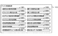
図13は、本実施の形態に係るディスク制御装置110における前述したデータの更新処理を実現する機能を示すブロック図である。ディスク制御装置110は、書き込み要求受信部1301、第一の書き込み部1302、ジャーナル書き込み部1303、第二の書き込み部1304、スプリット指示命令受信部1305、スプリット解除命令受信部1306、スプリット指示記憶部1307、スプリット解除記憶部1308、未反映情報記憶部1309、読み出し要求受信部1310、識別子取得部1311、重複範囲取得部1312、仮想論理ボリューム読み出し部1313、読み出しデータ送信部1314を備えている。各部1301〜1314は、図1〜図3に示すディスクアレイ装置10におけるCPU203及びCPU303、図4に示すディスクアレイ装置10におけるCPU141がメモリ202,302,142又はNVRAM204,304に格納されているプログラムを実行することにより実現される。
FIG. 13 is a block diagram showing a function for realizing the above-described data update processing in the
==ペア及びグループ==
図14は、第一の記憶デバイス1201の論理ボリューム121と第二の記憶デバイス1202の論理ボリューム121との関係を示す図である。第一の記憶デバイス1201の論理ボリューム121は、第二の記憶デバイス1202の論理ボリューム121と対応付けられている。この対応付けにおける第一の記憶デバイス1201の論理ボリューム121を主論理ボリューム、第二の記憶デバイス1202の論理ボリューム121を副論理ボリュームと称する。この対応付けはペアと呼ばれ、図15に示すペア管理テーブル1501に主論理ボリュームの識別子と副論理ボリュームの識別子とが対応付けられて記憶されている。また、第一の記憶デバイス1201の論理ボリューム121は一つ又は複数の論理ボリューム121をまとまりとするグループを形成している。グループは、例えば、データベースサーバ40ごとや、データベースサーバ40が提供するデータベース・インスタンスごとに形成される。つまり、データベースサーバ40は第一の記憶デバイス1201の論理ボリューム121をグループ単位で使用していると言うことができる。従って、第一の記憶デバイス1201の論理ボリューム121をグループ単位でバックアップすることが必要となる。グループにはグループを示すグループIDが付与され、図16に示すグループ管理テーブル1601に論理ボリューム121の識別子とグループIDとの対応付けが記憶されている。ペア管理テーブル1501及びグループ管理テーブル1601はメモリ1003に記憶されており、管理端末136や情報処理装置20などから登録される。
== Pair and group ==
FIG. 14 is a diagram showing the relationship between the
==ジャーナルデータ==
図17は、第三の記憶デバイス1203に書き込まれるジャーナルデータを示す図である。ジャーナルデータ1701は、ジャーナル部1702及び更新ストリーム部1703からなる。
== Journal data ==
FIG. 17 is a diagram showing journal data written to the
ジャーナル部1702は、グループID、シーケンスID、更新時刻、更新位置情報、及び更新ストリームオフセットで構成されている。データベースサーバ40から第一の記憶デバイス1201の論理ボリューム121に更新データを書き込む要求を受信すると、ディスク制御装置110は第三の記憶デバイス1203にジャーナルデータ1701を記憶する。グループIDは、当該論理ボリューム121が属するグループのグループIDである。シーケンスIDは、第一の記憶デバイス1201における更新データの更新順序を示すものであり、グループごとに管理されている連続番号である。ジャーナルデータ1701に格納されている更新データは、グループごとにシーケンスID順に第二の記憶デバイス1202の論理ボリューム121に書き込まれる。更新時刻は、ディスク制御装置110がジャーナルデータ1701を記憶する際に計時機構1201から取得した日付と時刻である。したがって、シーケンスIDの順序と更新時刻の順序は同じである。更新位置情報には、当該論理ボリューム121の識別子と当該論理ボリューム121において更新データが格納された位置情報とが記憶されている。なお、データが格納された位置情報とは、例えば、開始アドレス及び開始アドレスからのデータ長などで示される情報である。更新ストリームオフセットには、更新データの更新ストリーム部1703における位置情報が記憶されている。更新ストリーム部1703には、更新データが更新ストリームオフセットで示される位置に記憶されている。
The journal unit 1702 includes a group ID, a sequence ID, an update time, update position information, and an update stream offset. When receiving a request for writing update data from the
また、ディスク制御部110が後述するスプリット指示命令を受信した場合は、更新位置情報にスプリット指示命令を受信したことを示すデータが記憶される。グループIDには、スプリット指示命令で指定されたグループIDが記憶される。シーケンスIDには、スプリット指示命令で指定されたグループIDのシーケンスIDが記憶される。更新時刻には、計時機構1201から取得した日付と時刻が記憶される。このように、スプリット指示命令に伴いジャーナル部1701に書き込まれたデータをスプリット指示データと称する。そして、ディスク制御部110が後述するスプリット解除命令を受信した場合は、更新位置情報にスプリット解除命令を受信したことを示すデータが記憶される。このように、スプリット解除命令に伴いジャーナル部1701に書き込まれたデータをスプリット解除データと称する。
Further, when the
なお、第二の記憶デバイス1202の論理ボリューム121への反映が完了した更新データを示すジャーナルデータ1701の記憶領域は空き領域として管理され、別の更新データを示すジャーナルデータ1701の記憶領域として再利用される。
Note that the storage area of the
==スプリット運用==
次に、本実施の形態において静止化データを作成してデータのバックアップを行う概要について説明する。図18は、静止化データを作成するためのスプリット指示命令を受信した場合の、ディスクアレイ装置10の状態遷移を示す図である。
== Split operation ==
Next, an outline of creating static data and backing up data in the present embodiment will be described. FIG. 18 is a diagram showing a state transition of the
まず、通常運用の状態(S1801)においては、第三の記憶デバイス1203のジャーナルデータ1701から、更新時刻と現在時刻との差が検出時間1205を超えている更新データが抽出され、第二の記憶デバイス1202に書き込まれている。
First, in the normal operation state (S1801), update data in which the difference between the update time and the current time exceeds the
ディスクアレイ装置10は、データベースサーバ40またはバックアップサーバ1803等からスプリット指示命令を受信すると、仮想デバイス1801を作成する状態(S1802)へと遷移する。バックアップサーバ1803とは、図1及び図4における情報処理装置10に相当する装置である。バックアップサーバ1803は、ディスクアレイ装置10に格納されているデータを読み出し、外部の記憶媒体にバックアップする機能を備えている。
When the
図18のS1802は、ディスクアレイ装置10がスプリット指示命令を18時(スプリット時刻)に受信してから5分経過した状態を示している。なお、図18の例では検出時間は2時間である。S1802において、第二の記憶デバイス1202には、現在時刻の2時間前である16:05までの更新データが反映されている。つまり、16:05から18:00までの更新データは、まだ第二の記憶デバイス1202に反映されず、第三の記憶デバイス1203に格納されている。
S1802 in FIG. 18 shows a state in which five minutes have elapsed since the
そこで、18:00における第一の記憶デバイスの静止化データとして仮想デバイス1801が提供される。仮想デバイス1801には、仮想的な論理ボリュームである仮想論理ボリュームが設けられている。仮想論理ボリュームの識別子と第二の記憶デバイス1202の論理ボリューム121の識別子との対応は、図19に示す仮想論理ボリューム管理テーブル1901に記憶されている。仮想論理ボリューム管理テーブル1901はメモリ1003に記憶され、管理端末136や情報処理装置20などから登録される。
Therefore, the
ディスク制御装置110は、更新時刻がスプリット時刻より早いジャーナルデータ1701の更新位置情報を抽出し、未反映情報としてメモリ1003に記憶している。未反映情報の記憶方式は、例えば、第二の記憶デバイス1202の記憶領域を複数のセグメントに分割し、このセグメント単位に未反映の更新データがあるかどうかを示すビットマップ方式などである。ディスク制御装置110は、バックアップサーバ1802から仮想論理ボリュームに対するデータの読み出し要求を受信すると、未反映情報で示される位置に格納されているデータについては、第三の記憶デバイス1203からデータを読み出す。また、ディスク制御装置110は、未反映情報で示される位置以外に格納されているデータについては、第二の記憶デバイス1202から読み出す。これにより、バックアップサーバ1802に対して第一の記憶デバイス1201の18時の静止化データを提供することができる。
The
仮想デバイス1801が提供されている間も、第三の記憶デバイス1203から第二の記憶デバイス1202への更新データの反映は行われている。そのため、ディスク制御装置110は、仮想デバイス1801を静止化データとするために、更新時刻がスプリット時刻以降の更新データを第二の記憶デバイス1202に反映しない。この状態を示しているのが、S1803である。S1803においては、第二の記憶デバイス1202にはスプリット時刻である18時までの更新データが反映されている。したがって、第二の記憶デバイス1202と仮想デバイス1801とは一致している。
While the
ディスクアレイ装置10は、データベースサーバ40またはバックアップサーバ1801等からスプリット解除命令を受信すると、第三の記憶デバイス1203に格納されている、更新時刻と現在時刻との差が検出時間1205を超えている更新データの第二の記憶デバイス1202への反映を再開する。S1804は、この状態を示している。そして、この反映が完了すると、通常運用の状態(S1801)に戻る。
When the
なお、仮想デバイス1801を用いずに、スプリット指示命令を受信するとディスク制御装置110は更新時刻がスプリット時刻より早い更新データを、更新時刻と現在時刻との差が検出時間1205を超えているかどうかにかかわらず、第二の記憶デバイス1202に反映するものとしてもよい。この場合、バックアップサーバ1802は、仮想デバイス1801ではなく、第二の記憶デバイス1202からデータを読み出してバックアップを行う。
When the split instruction command is received without using the
==動作の説明==
以上に説明した、本実施の形態におけるバックアップ方式を実現するための、ディスク制御装置110の各部1301〜1314の動作を説明する。
== Description of operation ==
The operation of each
==第三の記憶デバイスへの書き込み==
図20は、ディスク制御装置110がデータベースサーバ40から第一の記憶デバイス1201の論理ボリューム121に対するデータの書き込み要求を受信した際の処理を示すフローチャートである。
== Write to third storage device ==
FIG. 20 is a flowchart showing processing when the
書き込み要求受信部1301は、データベースサーバ40から第一の記憶デバイス1201の論理ボリューム121に対するデータの書き込み要求と書き込み用のデータとを受信する(S2001)。第一の書き込み部1302は、当該データを第一の記憶デバイス1201の当該書き込み要求で指定される論理ボリューム121に書き込む(S2002)。ジャーナル書き込み部1303は、当該データに対するジャーナルデータ1701を第三の記憶デバイス1203に書き込む(S2003)。そして、ジャーナル書き込み部1303は、データベースサーバ40に対して当該データの書き込み完了通知を送信する(S2004)。
The write
なお、当該ジャーナルデータ1701の生成は次のように行われる。ジャーナル書き込み部1303は、当該論理ボリュームの識別子に対応するグループIDをグループ管理テーブル1601から取得し、当該ジャーナルデータ1701のグループIDに設定する。ジャーナル書き込み部1303は、取得したグループIDにおいて前回付与されたシーケンスIDに1加算し、当該ジャーナルデータ1701のシーケンスIDに設定する。ジャーナル書き込み部1303は、計時機構1204から現在の日時を取得し、当該ジャーナルデータ1701の更新時刻に設定する。ジャーナル書き込み部1303は、当該論理ボリュームの識別子と当該データが書き込まれた位置情報とを当該ジャーナルデータ1701の更新位置情報に設定する。ジャーナル書き込み部1303は、更新ストリーム部1703において次にデータが格納される位置を当該ジャーナルデータ1701の更新ストリームオフセットに設定する。そして、ジャーナル書き込み部1303は、当該データを更新ストリーム部1703に格納する。
The
また、ジャーナルデータ1701は、第三の記憶デバイス1203の論理ボリューム121に書き込まれる前に、メモリ1003に書き込まれる。メモリ1003が冗長構成で、かつ不揮発性である場合、メモリ1003にジャーナルデータ1701が書き込まれた時点でジャーナル書き込み部1303がデータベースサーバ40に対して当該データの書き込み完了通知を送信することとしてもよい。
The
==スプリット指示==
図21は、ディスク制御装置110がスプリット指示命令を受信した際の処理を示すフローチャートである。
== Split instruction ==
FIG. 21 is a flowchart showing processing when the
スプリット指示命令受信部1305は、データベースサーバ40やバックアップサーバ1801等からスプリット指示命令を受信する(S2101)。スプリット指示記憶部1307は、スプリット指示データを第三の記憶デバイス1203に書き込む(S2102)。なお、スプリット指示データの生成は次のように行われる。スプリット指示記憶部1307は、スプリット指示命令で指定されるグループIDを当該スプリット指示データのグループIDに設定する。スプリット指示記憶部1307は、当該グループIDにおいて前回付与されたシーケンスIDに1加算し、当該スプリット指示データのシーケンスIDに設定する。スプリット指示記憶部1307は、計時機構1204から現在の日時を取得し、当該スプリット指示データの更新時刻に設定する。スプリット指示記憶部1307は、スプリット指示命令を受信したことを示すデータを当該スプリット指示データの更新位置情報に設定する。
そして、未反映情報記憶部1309は、更新時刻がスプリット時刻より早いジャーナルデータ1701の更新位置情報である未反映情報をメモリ1003に記憶する。なお、更新時刻がスプリット時刻より早いかどうかの判断は、更新時刻を直接比較することにより行われてもよいし、シーケンスIDを比較することにより行われてもよい。
The split instruction
The unreflected
==スプリット解除==
図22は、ディスク制御装置110がスプリット解除命令を受信した際の処理を示すフローチャートである。
スプリット解除命令受信部1306は、データベースサーバ40やバックアップサーバ1801等からスプリット解除命令を受信する(S2201)。スプリット解除記憶部1308は、スプリット解除データを第三の記憶デバイス1203に書き込む(S2202)。つまり、スプリット解除記憶部1308は、スプリット指示命令で指定されるグループIDが設定されているスプリット指示データの更新位置情報にスプリット解除命令を受信したことを示すデータを設定する。
== Split release ==
FIG. 22 is a flowchart showing processing when the
The split cancellation
==第二の記憶デバイスへの更新データの反映==
図23は、ディスク制御装置110が第三の記憶デバイス1203に格納されている更新データを第二の記憶デバイス1202に反映する処理を示すフローチャートである。
第二の書き込み部1304は、メモリ1003に格納されている検出時間1205を取得する(S2301)。第二の書き込み部1304は、計時機構1204から日付と時刻(現在時刻)を取得する(S2302)。第二の書き込み部13024、第三の記憶デバイス1203に格納されているジャーナルデータ1701を参照し(S2303)、スプリット指示データがあり、かつ、スプリット解除データがないかどうかを確認する(S2304)。
== Reflection of update data to the second storage device ==
FIG. 23 is a flowchart showing processing in which the
The
スプリット指示データがあり、かつ、スプリット解除データがない場合、第二の書き込み部1304は、当該スプリット指示データとグループIDが同一で、更新時刻と現在時刻との差が検出時間1205を超えており、更新時刻がスプリット時刻より早いジャーナルデータを選択する(S2305)。条件に該当するジャーナルデータ1701がない場合は、再びS2302からの処理を実行する。なお、更新時刻がスプリット時刻より早いジャーナルの選択は、更新時刻を比較することにより行われてもよいし、シーケンスIDを比較することにより行われてもよい。
スプリット指示データがないか、またはスプリット解除データがある場合、第二の書き込み部1304は、更新時刻と現在時刻との差が検出時間1205を超えているジャーナルデータ1701を選択する(S2306)。条件に該当するジャーナルデータ1701がない場合は、再びS2302からの処理を実行する。
When there is split instruction data and there is no split release data, the
If there is no split instruction data or there is split release data, the
第二の書き込み部1304は、選択したジャーナルデータ1701の更新位置情報に設定されている論理ボリューム121の識別子に対応する副論理ボリュームの識別子をペア管理テーブル1501から取得する(S2307)。第二の書き込み部1304は、選択したジャーナルデータ1701の更新データを、取得した副論理ボリュームの識別子で示される第二の記憶デバイス1202の論理ボリューム121のジャーナルデータ1701の位置情報で示される場所に書き込む(S2308)。なお、ジャーナルデータ1701が複数ある場合、第二の書き込み部1304は、シーケンスID順、つまり更新時刻の早い順に更新データを第二の記憶デバイス1202の論理ボリューム121に書き込む。第二の記憶デバイス1202の論理ボリューム121への書き込みが完了すると、第二の書き込み部1304は、メモリ1003に記憶されている当該更新データの未反映情報を削除する(S2309)。
The
なお、前述のS2305のステップを、第二の書き込み部1304が更新時刻と現在時刻との比較を行わず、更新時刻がスプリット時刻より早いジャーナルデータを選択すると変更することにより、仮想デバイス1801を設けずに第二の記憶デバイス1202を第一の記憶デバイス1201の静止化データとすることができる。
The
==仮想論理ボリュームの読み出し==
図24は、ディスク制御装置110が仮想デバイス1801の仮想論理ボリュームに対する読み出し要求を受信した際の処理を示すフローチャートである。
== Reading virtual logical volume ==
FIG. 24 is a flowchart showing processing when the
読み出し要求受信部1310は、バックアップサーバ1802から仮想デバイス1801の仮想論理ボリュームの識別子が指定された読み出し要求を受信する(S2401)。識別子取得部1311は、読み出し要求で指定された仮想論理ボリュームの識別子に対応する論理ボリューム121の識別子を仮想論理ボリューム管理テーブル1901から取得する(S2402)。重複範囲取得部1312は、読み出し要求で指定される位置情報とメモリ1003に記憶されている未反映情報の位置情報とで重複している範囲を取得する(S2403)。未反映情報が開始アドレスとブロック長とで示されている場合、重複している範囲とは、読み出し要求で指定される位置情報で示される範囲と未反映情報の位置情報で示される範囲とで重なりあう部分である。また、未反映情報がセグメント単位でのビットマップで表現されている場合、重複している範囲とは、読み出し要求で指定される位置情報で示される範囲のうちで未反映情報のビットマップで未反映のビットが設定されているセグメントである。
The read
仮想論理ボリューム読み出し部1313は、重複している範囲については第三の記憶デバイス1203に格納されているジャーナルデータ1701から読み出し(S2404)、重複していない範囲については第二の記憶デバイス1202の論理ボリューム121から読み出す(S2405)。そして、読み出しデータ送信部1314は、読み出されたデータをバックアップサーバ1802に送信する(S2406)。
The virtual logical
以上、本実施の形態におけるバックアップ方式を実現するための、ディスク制御装置110の各部1301〜1314の動作を説明した。
The operation of each
これにより、第二の記憶デバイス1202の論理ボリューム121を第一の記憶デバイス1201の論理ボリューム121の検出時間1205前の状態とすることができる。ソフトウェアの障害等により不正なデータが第一の記憶デバイス1201の論理ボリューム121に書き込まれた場合、検出時間1205の間は、第二の記憶デバイス1202の論理ボリューム121には不正なデータが書き込まれない。
As a result, the
例えば、情報処理装置20がデータベースサーバ40であり、第一の記憶デバイス1201の論理ボリューム121がデータベースのデータ格納領域であるとする。このような場合、データベースサーバ40は第一の記憶デバイス1201の論理ボリューム121に書き込んだデータに対するある時点からのREDOログを別の記憶領域に記憶している。したがって、第一の記憶デバイス1201の論理ボリューム121に不正なデータが書き込まれた場合、第二の記憶デバイス1202の論理ボリューム121に記憶されている検出時間1205前のデータとREDOログとを用いて、第一の記憶デバイス1201の論理ボリューム121を不正なデータが書き込まれる直前の状態にまで復元することができる。つまり、磁気テープ等の媒体に保存されているデータを用いることなく、ディスクアレイ装置10内のデータを用いて第一の記憶デバイス1201の論理ボリューム121のデータを復元することができるため、復元作業に要する時間を短縮することが可能である。
For example, it is assumed that the
また、第一の記憶デバイス1201の論理ボリューム121を主論理ボリュームとし、主論理ボリュームに対する副論理ボリューム(レプリカボリューム)を2つ設ける従来のデータバックアップ方式と比較して、記憶容量を削減することが可能である。副論理ボリュームを2つ設ける従来のデータバックアップ方式では、主論理ボリュームと副論理ボリュームとで、第一の記憶デバイス1201の3倍の記憶容量が必要であった。本発明の方式で必要となる記憶容量は、第三の記憶デバイス1203に格納するジャーナルデータの量に依存している。通常、1日のデータベース更新量は主論理ボリュームの20%までであることが多い。つまり、検出時間1205を1日とする場合、第三の記憶デバイス1203の記憶容量は第一の記憶デバイス1201の25%を確保すれば十分である。したがって、第一の記憶デバイス1201と第二の記憶デバイス1202と第三の記憶デバイス1203とで、第一の記憶デバイス1201の2.25倍の記憶容量でよいこととなる。検出時間1205を数時間とすることができる場合は、必要な記憶容量を更に削減することが可能である。つまり、障害が発生した場合にディスクアレイ装置10内に存在するデータで第一の記憶デバイス1201の論理ボリューム121を復旧するバックアップ方式において、必要な記憶容量を削減でき、ディスクアレイ装置10の導入コストを削減することができる。
In addition, the storage capacity can be reduced as compared with the conventional data backup method in which the
また、検出時間1205がメモリ1003に記憶されていることにより、検出時間1205を管理端末136や情報処理装置20等から登録することが可能となる。つまり、ソフトウェアの不具合や人為的な操作ミス等により発生する第一の記憶デバイス1201の論理ボリューム121に不正なデータが書き込まれていることを検出可能な時間を、業務やソフトウェアの特性に応じて変更することが可能である。したがって、第三の記憶デバイス1203にジャーナルデータ1701を格納するために必要な記憶容量を、業務やソフトウェアの特性に応じて変更することができる。
Since the
また、第一の記憶デバイス1201を構成するハードディスクドライブ120と第二の記憶デバイス1202を構成するハードディスクドライブ120とを物理的に別のものとすることができる。第一の記憶デバイス1201を構成するハードディスクドライブ120にハードウェア障害が発生した場合でも、第二の記憶デバイス1202には、検出時間1205前に第一の記憶デバイス1201の論理ボリューム121に記憶されていたデータが記憶されている。情報処理装置20がデータベースサーバ40で、ディスクアレイ装置10内に第一の記憶デバイス1201の論理ボリューム121に書き込まれたREDOログが存在する場合、第二の記憶デバイス1202の論理ボリューム121とREDOログとで、第一の記憶デバイス1201の論理ボリューム121のデータを復元することができる。データの復元には、磁気テープ等の媒体に保存されているデータを用いないため、復元作業に要する時間を短縮することが可能である。
Further, the
つまり、第一の記憶デバイス1201の論理ボリューム121のある時点の静止化データを用いることなく、継続的に更新が行われている第二の記憶デバイス1201を用いて第一の記憶デバイス1201の論理ボリューム121のデータを迅速に復旧することができる。
That is, the logical data of the
また、第一の記憶デバイス1201を構成するハードディスクドライブ120と第二の記憶デバイス1202及び第三の記憶デバイス1203を構成するハードディスクドライブ120とを物理的に別のものとすることができる。第三の記憶デバイス1203に格納されているジャーナルデータ1701を用いて第二の記憶デバイス1202の論理ボリューム121を更新する際に、第一の記憶デバイス1201からデータを読み出す必要がない。つまり、情報処理装置20から第一の記憶デバイス1201に対するデータ入出力処理の性能に与える影響が少ない。
Further, the
また、第一の記憶デバイス1201を構成するハードディスクドライブ120にハードウェア障害が発生した場合、第二の記憶デバイス1202の論理ボリューム121と第三の記憶デバイス1203に格納されているジャーナルデータ1701とを用いて第一の記憶デバイス1201の論理ボリューム121のデータを復元することができる。この場合においても、データの復元には磁気テープ等の媒体に保存されているデータを用いないため、復元作業に要する時間を短縮することが可能である。
Further, when a hardware failure occurs in the
また、スプリット時刻から検出時間を経過後、第一の記憶デバイス1201のスプリット時刻の状態を第二の記憶デバイス1202上に作成することが可能となる。この状態において、第二の記憶デバイス1202の論理ボリューム121を磁気テープ等の記憶媒体にバックアップすることが可能となる。したがって、ディスクアレイ装置10全体の障害や広域災害等に備えたデータのバックアップを行うことが可能となる。
In addition, after the detection time has elapsed from the split time, the split time state of the
また、スプリット指示後直ちに、第二の記憶デバイス1202の論理ボリューム121の仮想論理ボリュームを用いて、第一の記憶デバイス1201の論理ボリューム121のスプリット時刻におけるデータを磁気テープ等にバックアップすることが可能である。つまり、第三の記憶デバイス1203に格納されている更新時刻がスプリット時刻より早いジャーナルデータが第二の記憶デバイス1202の論理ボリューム121に反映されるのを待つ必要がない。そのため、データのバックアップを容易に行うことが可能となる。
In addition, immediately after the split instruction, the data at the split time of the
また、スプリット指示命令を受信すると、検出時間にかかわらず、更新時刻がスプリット時刻より早いジャーナルデータの更新データを第二の記憶デバイス1202の論理ボリューム121に反映することもできる。これにより、第二の記憶デバイス1202の論理ボリューム121を用いて、第一の記憶デバイス1201の論理ボリューム121のスプリット時刻におけるデータを磁気テープ等にバックアップすることが可能である。つまり、バックアップ処理中に仮想論理ボリュームを形成する必要がないため、ディスクアレイ装置10の負荷が軽減され、バックアップ処理時間が短縮される。
When the split instruction command is received, the update data of the journal data whose update time is earlier than the split time can be reflected in the
また、スプリット指示命令を第一の記憶デバイス1201の論理ボリューム121のグループIDを指定して行うことができる。第一の記憶デバイス1201を、複数の情報処理装置20が使用している場合や、情報処理装置10上で複数の業務アプリケーションが稼働している場合等に、情報処理装置20や業務アプリケーションごとに論理ボリューム121にグループIDを付与することで、グループID単位でデータのバックアップを行うことが可能となる。
Further, the split instruction command can be issued by designating the group ID of the
例えば、情報処理装置20がデータベースサーバであり、データベースサーバが使用しているデータベース・インスタンスが2つあるとする。各データベース・インスタンスがデータ格納領域として用いている第一の記憶デバイス1201の論理ボリューム121に、異なるグループIDを付与する。スプリット指示命令及びスプリット解除命令は、このグループID単位で行われる。つまり、データベース・インスタンス単位でデータのバックアップを行うことが可能となる。また、例えば、業務アプリケーションごとに使用する論理ボリューム121が分かれている場合、業務アプリケーション単位でのデータのバックアップを行うことが可能となる。
For example, it is assumed that the
また、グループIDを考慮する場合においても、当該グループIDに対する仮想論理ボリュームを用いて、第一の記憶デバイス1201の論理ボリューム121のスプリット時刻におけるデータを磁気テープ等にバックアップすることが可能である。つまり、バックアップを開始する前に、第三の記憶デバイスに格納されている更新時刻がスプリット時刻より早いジャーナルデータが第二の記憶デバイスの論理ボリュームに反映されるのを待つ必要がない。そのため、データのバックアップを容易に行うことが可能となる。
Even when a group ID is considered, it is possible to back up the data at the split time of the
また、グループIDを考慮する場合においても、スプリット指示命令を受信すると、当該グループIDについては検出時間にかかわらず更新時刻がスプリット時刻より早いジャーナルデータの更新データを第二の記憶デバイス1202の論理ボリューム121に反映することもできる。これにより、第二の記憶デバイス1202の論理ボリューム121を用いて、第一の記憶デバイス1201の論理ボリューム121のスプリット時刻におけるデータを磁気テープ等にバックアップすることが可能である。つまり、バックアップ処理中に仮想論理ボリュームを形成する必要がないため、ディスクアレイ装置10の負荷が軽減され、バックアップ処理時間が短縮される。
Even when the group ID is taken into consideration, when the split instruction command is received, the update data of the journal data whose update time is earlier than the split time is received for the group ID regardless of the detection time. 121 can also be reflected. As a result, it is possible to back up the data at the split time of the
以上、本実施の形態について説明したが、上記実施例は本発明の理解を容易にするためのものであり、本発明を限定して解釈するためのものではない。本発明は、その趣旨を逸脱することなく、変更、改良され得ると共に、本発明にはその等価物も含まれる。 Although the present embodiment has been described above, the above examples are for facilitating the understanding of the present invention, and are not intended to limit the present invention. The present invention can be changed and improved without departing from the gist thereof, and the present invention includes equivalents thereof.
10 ディスクアレイ装置 20 情報処理装置
30 クライアント端末 40 データベースサーバ
110 ディスク制御装置 120 ハードディスクドライブ
121 論理ボリューム 131 チャネル制御部
132 ディスク制御部 133 共有メモリ
134 キャッシュメモリ 135 スイッチング制御部
136 管理端末 141 CPU
142 メモリ 143 ホストインタフェース
144 ディスクインタフェース 145 キャッシュメモリ
146 データコントローラ 201 インタフェース部
202 メモリ 203 CPU
204 NVRAM 205 コネクタ
301 インタフェース部 302 メモリ
303 CPU 304 NVRAM
305 コネクタ 501 データ領域
502 REDOログ領域 503 テーブル
504 テーブル 505 データベースバッファ
506 REDOログバッファ 601 CPU
602 メモリ 603 記憶装置
604 ポート 605 記録媒体読取装置
606 入力装置 607 出力装置
608 記録媒体 701 CPU
702 メモリ 703 記憶装置
704 LANインタフェース 705 ストレージインタフェース
706 記録媒体読取装置 707 記録媒体
1001 レプリカボリューム 1002 レプリカボリューム
1003 メモリ 1004 差分セグメントビットマップ
1101 プール 1102 仮想レプリカボリューム
1201 第一の記憶デバイス 1202 第二の記憶デバイス
1203 第三の記憶デバイス 1204 計時機構
1205 検出時間 1301 書き込み要求受信部
1302 第一の書き込み部 1303 ジャーナル書き込み部
1304 第二の書き込み部 1305 スプリット指示命令受信部
1306 スプリット解除命令受信部 1307 スプリット指示記憶部
1308 スプリット解除記憶部 1309 未反映情報記憶部
1310 読み出し要求受信部 1311 識別子取得部
1312 重複範囲取得部 1313 仮想論理ボリューム読み出し部
1314 読み出しデータ送信部 1501 ペア管理テーブル
1601 グループ管理テーブル 1701 ジャーナルデータ
1702 ジャーナル部 1703 更新ストリーム部
1901 仮想論理ボリューム管理テーブル
DESCRIPTION OF
142
204
305
602
702
Claims (15)
一又は複数の論理ボリュームが形成されている第一の記憶デバイスと、
一又は複数の論理ボリュームが形成されている第二の記憶デバイスと、
第三の記憶デバイスと
に対するデータの書き込みまたは読み出しを行うディスク制御装置であって、
前記第一の記憶デバイスの前記論理ボリュームの識別子である主論理ボリュームの識別子と前記第二の記憶デバイスの前記論理ボリュームの識別子である副論理ボリュームの識別子とが対応付けられたペア管理テーブルと、任意の値に設定された検出時間と、を記憶するメモリと、
計時機構と、
前記情報処理装置から前記第一の記憶デバイスの前記論理ボリュームに対するデータの書き込み要求と前記データとを受信する書き込み要求受信部と、
前記書き込み要求を受信すると前記データを前記第一の記憶デバイスの前記論理ボリュームに書き込む第一の書き込み部と、
前記データが書き込まれている前記第一の記憶デバイスの前記論理ボリュームの識別子、当該論理ボリューム内の前記データが格納されている位置情報、前記計時機構より取得される現在時刻である更新時刻、及び前記データで構成されるジャーナルデータを前記第三の記憶デバイスに書き込むジャーナル書き込み部と、
前記第三の記憶デバイスに記憶されている複数の前記ジャーナルデータのそれぞれの前記更新時刻と前記メモリに記憶されている前記検出時間とを参照し、前記計時機構より取得される現在時刻と前記更新時刻との差が前記検出時間を超えている前記ジャーナルデータを前記複数のジャーナルデータの中から選択し、選択された前記ジャーナルデータの前記更新時刻が早い順に前記ジャーナルデータの前記論理ボリュームの識別子と前記位置情報と前記データとを参照し、当該論理ボリュームの識別子が前記主論理ボリュームの識別子である前記副論理ボリュームの識別子を前記ペア管理テーブルから取得し、当該データを前記第二の記憶デバイスの当該副論理ボリュームの識別子で示される前記論理ボリュームの当該位置情報で示される場所に書き込む第二の書き込み部と、
前記情報処理装置から前記第二の記憶デバイスへの前記データの書き込みを中断するスプリット指示命令を受信するスプリット指示命令受信部と、
前記情報処理装置から前記第二の記憶デバイスへの前記データの書き込みを再開するスプリット解除命令を受信するスプリット解除命令受信部と、
前記スプリット指示命令を受信すると前記スプリット指示命令を受信したことを示すデータと前記計時機構より取得される現在時刻であるスプリット時刻とで構成されるスプリット指示データを前記第三の記憶デバイスに書き込むスプリット指示記憶部と、
前記スプリット解除命令を受信すると前記スプリット解除命令を受信したことを示すデータであるスプリット解除データを前記第三の記憶デバイスに書き込むスプリット解除記憶部と
を有し、
前記第二の書き込み部は前記第三の記憶デバイスに前記スプリット指示データが記憶され、かつ、前記スプリット解除データが記憶されていない場合は、前記スプリット指示データの前記スプリット時刻を参照し、前記更新時刻が当該スプリット時刻より遅い前記ジャーナルデータの前記データを前記第二の記憶デバイスに書き込まない
ことを特徴とするディスク制御装置。 It is connected to the information processing device so that it can communicate,
A first storage device in which one or more logical volumes are formed;
A second storage device in which one or more logical volumes are formed;
A disk controller for writing or reading data to or from a third storage device,
A pair management table in which an identifier of a primary logical volume that is an identifier of the logical volume of the first storage device is associated with an identifier of a secondary logical volume that is an identifier of the logical volume of the second storage device; A memory for storing a detection time set to an arbitrary value;
A timing mechanism;
A write request receiving unit that receives a data write request and the data from the information processing apparatus to the logical volume of the first storage device;
A first writing unit that writes the data to the logical volume of the first storage device upon receipt of the write request;
An identifier of the logical volume of the first storage device in which the data is written, location information where the data in the logical volume is stored, an update time which is a current time obtained from the timekeeping mechanism, and A journal writing unit for writing journal data composed of the data to the third storage device;
With reference to the update time of each of the plurality of journal data stored in the third storage device and the detection time stored in the memory, the current time and the update acquired from the timing mechanism The journal data whose difference from the time exceeds the detection time is selected from the plurality of journal data, and the logical volume identifier of the journal data is selected in order of the update time of the selected journal data. The location information and the data are referenced, the secondary logical volume identifier whose logical volume identifier is the primary logical volume identifier is obtained from the pair management table, and the data is stored in the second storage device. The location indicated by the location information of the logical volume indicated by the identifier of the secondary logical volume A second write unit for writing the,
A split instruction command receiving unit for receiving a split instruction command for interrupting writing of the data from the information processing apparatus to the second storage device;
A split release command receiving unit for receiving a split release command for resuming writing of the data from the information processing apparatus to the second storage device;
When the split instruction command is received, the split instruction data is written to the third storage device, which is composed of data indicating that the split instruction command has been received and the split time that is the current time obtained from the timing mechanism. An instruction storage unit;
A split cancellation storage unit that writes split cancellation data, which is data indicating that the split cancellation command has been received, to the third storage device when the split cancellation command is received;
Have
The second writing unit refers to the split time of the split instruction data when the split instruction data is stored in the third storage device and the split release data is not stored, and the update is performed. The disk control apparatus , wherein the data of the journal data whose time is later than the split time is not written to the second storage device .
前記第一の記憶デバイスを構成する一又は複数のハードディスクドライブと、前記第二の記憶デバイス及び前記第三の記憶デバイスを構成する一又は複数のハードディスクドライブとが物理的に別であることを特徴とするディスク制御装置。 The disk control device according to claim 1,
One or more hard disk drives constituting the first storage device and one or more hard disk drives constituting the second storage device and the third storage device are physically separate. The disk controller.
前記第一の記憶デバイスを構成する一又は複数のハードディスクドライブと、前記第二の記憶デバイスを構成する一又は複数のハードディスクドライブとが物理的に別であることを特徴とするディスク制御装置。 The disk control device according to claim 1,
One or more hard disk drives constituting the first storage device and one or more hard disk drives constituting the second storage device are physically different from each other.
前記第二の記憶デバイスの前記論理ボリュームに対応する仮想的な論理ボリュームである仮想論理ボリュームが設けられ、前記論理ボリュームの識別子と前記仮想論理ボリュームの識別子との対応付けが前記メモリに仮想論理ボリューム管理テーブルとして記憶され、
前記第三の記憶デバイスを参照し、前記スプリット指示データが記憶され、かつ、前記スプリット解除データが記憶されていない場合は、前記更新時刻が前記スプリット指示データの前記スプリット時刻より早い前記ジャーナルデータの前記論理ボリュームの識別子と前記位置情報とで構成される未反映情報を前記メモリに記憶する未反映情報記憶部と、
前記情報処理装置から前記仮想論理ボリュームの識別子と位置情報とが設定されているデータの読み出し要求を受信する読み出し要求受信部と、
前記読み出し要求の前記仮想論理ボリュームの識別子に対応する前記第二の記憶デバイスの前記論理ボリュームの識別子を前記仮想論理ボリューム管理テーブルから取得する識別子取得部と、
前記メモリに記憶されている前記未反映情報を参照し、前記識別子取得部により取得された前記第二の記憶デバイスの前記論理ボリュームの識別子と前記未反映情報の前記論理ボリュームの識別子とが同じ前記未反映情報において、前記読み出し要求に設定されている前記位置情報が示す範囲と前記未反映情報の前記位置情報が示す範囲とを比較して重複する範囲を取得する重複範囲取得部と、
前記読み出し要求に設定されている前記位置情報が示す範囲のうち前記重複する範囲については前記第三の記憶デバイスに記憶されている前記ジャーナルデータの前記データを読み出し、前記読み出し要求に設定されている前記位置情報が示す範囲のうち前記重複する範囲以外の範囲については前記識別子取得部により取得された前記第二の記憶デバイスの前記論理ボリュームの識別子で示される前記論理ボリュームに記憶されている前記データを読み出す仮想論理ボリューム読み出し部と、
前記仮想論理ボリューム読み出し部により読み出された前記データを前記情報処理装置に送信する読み出しデータ送信部と
を有することを特徴とするディスク制御装置。 The disk control device according to claim 1 ,
A virtual logical volume that is a virtual logical volume corresponding to the logical volume of the second storage device is provided, and the correspondence between the identifier of the logical volume and the identifier of the virtual logical volume is stored in the virtual logical volume in the memory. Stored as a management table,
With reference to the third storage device, when the split instruction data is stored and the split release data is not stored, the update time is earlier than the split time of the split instruction data. An unreflected information storage unit that stores unreflected information composed of the identifier of the logical volume and the position information in the memory;
A read request receiving unit that receives a read request for data in which the identifier and position information of the virtual logical volume are set from the information processing apparatus;
An identifier acquisition unit that acquires the identifier of the logical volume of the second storage device corresponding to the identifier of the virtual logical volume of the read request from the virtual logical volume management table;
The unreflected information stored in the memory is referred to, and the identifier of the logical volume of the second storage device acquired by the identifier acquisition unit and the identifier of the logical volume of the unreflected information are the same In the unreflected information, an overlapping range acquisition unit that acquires an overlapping range by comparing the range indicated by the position information set in the read request with the range indicated by the position information of the unreflected information;
Among the ranges indicated by the position information set in the read request, for the overlapping range, the data of the journal data stored in the third storage device is read and set in the read request. The data stored in the logical volume indicated by the identifier of the logical volume of the second storage device acquired by the identifier acquisition unit for a range other than the overlapping range of the range indicated by the position information A virtual logical volume reading unit for reading
A disk control apparatus comprising: a read data transmission unit that transmits the data read by the virtual logical volume reading unit to the information processing apparatus.
前記第二の書き込み部は前記第三の記憶デバイスに前記スプリット指示データが記憶され、かつ、前記スプリット解除データが記憶されていない場合は、前記更新時刻が当該スプリット時刻より早い前記ジャーナルデータの前記データを、前記更新時刻と前記計時機構より取得される現在時刻との差が前記検出時間を超えているかどうかにかかわらず、前記第二の記憶デバイスに書き込むこと
を特徴とするディスク制御装置。 The disk control device according to claim 1 ,
The second writing unit stores the split instruction data in the third storage device, and the update time is earlier than the split time when the split release data is not stored. A disk control device, wherein data is written to the second storage device regardless of whether or not a difference between the update time and a current time acquired from the timing mechanism exceeds the detection time.
前記第一の記憶デバイスの前記論理ボリュームにグループIDが付与され、前記論理ボリュームの識別子と前記グループIDとの対応付けが前記メモリにグループID管理テーブルとして記憶され、
前記ジャーナル書き込み部は、前記第一の記憶デバイスの前記データが書き込まれている前記論理ボリュームの識別子に対応する前記グループIDを前記グループID管理テーブルから取得し、当該グループIDを前記ジャーナルデータに設定して前記第三の記憶デバイスに書き込み、
前記情報処理装置から前記第二の記憶デバイスへの前記データの書き込みを中断するスプリット指示命令を受信するスプリット指示命令受信部と、
前記情報処理装置から前記第二の記憶デバイスへの前記データの書き込みを再開するスプリット解除命令を受信するスプリット解除命令受信部と、
前記スプリット指示命令を受信すると前記スプリット指示命令に設定されている前記グループIDと前記スプリット指示命令を受信したことを示すデータと前記計時機構より取得される現在時刻であるスプリット時刻とで構成されるスプリット指示データを前記第三の記憶デバイスに書き込むスプリット指示記憶部と、
前記スプリット解除命令を受信すると前記スプリット解除命令に設定されている前記グループIDと前記スプリット解除命令を受信したことを示すデータであるスプリット解除データを前記第三の記憶デバイスに書き込むスプリット解除記憶部と
を有し、
前記第二の書き込み部は、前記第三の記憶デバイスに前記スプリット指示データが記憶され、かつ、当該スプリット指示データの前記グループIDと同じ前記グループIDが設定されている前記スプリット解除データが記憶されていない場合は、前記スプリット指示データの前記グループIDと前記スプリット時刻とを参照し、前記ジャーナルデータの前記グループIDが前記スプリット指示データの当該グループIDと同じで、かつ、前記更新時刻が当該スプリット時刻より遅い前記ジャーナルデータの前記データを前記第二の記憶デバイスに書き込まないこと
を特徴とするディスク制御装置。 The disk control device according to claim 1,
A group ID is assigned to the logical volume of the first storage device, and an association between the identifier of the logical volume and the group ID is stored in the memory as a group ID management table,
The journal writing unit obtains the group ID corresponding to the identifier of the logical volume in which the data of the first storage device is written from the group ID management table, and sets the group ID in the journal data Write to the third storage device,
A split instruction command receiving unit for receiving a split instruction command for interrupting writing of the data from the information processing apparatus to the second storage device;
A split release command receiving unit for receiving a split release command for resuming writing of the data from the information processing apparatus to the second storage device;
When the split instruction command is received, it is composed of the group ID set in the split instruction command, data indicating that the split instruction command has been received, and the split time which is the current time acquired from the time measuring mechanism. A split instruction storage unit for writing split instruction data to the third storage device;
A split cancellation storage unit for writing into the third storage device, when the split cancellation command is received, the group ID set in the split cancellation command and split cancellation data that is data indicating that the split cancellation command has been received; Have
The second writing unit stores the split instruction data in which the split instruction data is stored in the third storage device and the same group ID as the group ID of the split instruction data is set. Otherwise, the group ID of the split instruction data and the split time are referred to, the group ID of the journal data is the same as the group ID of the split instruction data, and the update time is the split The disk control apparatus, wherein the data of the journal data later than the time is not written to the second storage device.
前記第二の記憶デバイスの前記論理ボリュームに対応する仮想的な論理ボリュームである仮想論理ボリュームが設けられ、前記論理ボリュームの識別子と前記仮想論理ボリュームの識別子との対応付けが前記メモリに仮想論理ボリューム管理テーブルとして記憶され、
前記第三の記憶デバイスを参照し、前記第三の記憶デバイスに前記スプリット指示データが記憶され、かつ、当該スプリット指示データの前記グループIDと同じ前記グループIDが設定されている前記スプリット解除データが記憶されていない場合は、当該スプリット指示データの前記グループIDと同じ前記グループIDが設定され、かつ、前記更新時刻が前記スプリット指示データの前記スプリット時刻より早い前記ジャーナルデータの前記論理ボリュームの識別子と前記位置情報とで構成される未反映情報を前記メモリに記憶する未反映情報記憶部と、
前記情報処理装置から前記仮想論理ボリュームの識別子と位置情報とが設定されているデータの読み出し要求を受信する読み出し要求受信部と、
前記読み出し要求の前記仮想論理ボリュームの識別子に対応する前記第二の記憶デバイスの前記論理ボリュームの識別子を前記仮想論理ボリューム管理テーブルから取得する識別子取得部と、
前記メモリに記憶されている前記未反映情報を参照し、前記識別子取得部により取得された前記第二の記憶デバイスの前記論理ボリュームの識別子と前記未反映情報の前記論理ボリュームの識別子とが同じ前記未反映情報において、前記読み出し要求に設定されている前記位置情報が示す範囲と前記未反映情報の前記位置情報が示す範囲とを比較して重複する範囲を取得する重複範囲取得部と、
前記読み出し要求に設定されている前記位置情報が示す範囲のうち前記重複する範囲については前記第三の記憶デバイスに記憶されている前記ジャーナルデータに設定されている前記データを読み出し、前記読み出し要求に設定されている前記位置情報が示す範囲のうち前記重複する範囲以外の範囲については前記識別子取得部により取得された前記第二の記憶デバイスの前記論理ボリュームの識別子で示される前記論理ボリュームに記憶されている前記データを読み出す仮想論理ボリューム読み出し部と、
前記仮想論理ボリューム読み出し部により読み出された前記データを前記情報処理装置に送信する読み出しデータ送信部と
を有することを特徴とするディスク制御装置。 The disk control device according to claim 6 , wherein
A virtual logical volume that is a virtual logical volume corresponding to the logical volume of the second storage device is provided, and the correspondence between the identifier of the logical volume and the identifier of the virtual logical volume is stored in the virtual logical volume in the memory. Stored as a management table,
With reference to the third storage device, the split release data in which the split instruction data is stored in the third storage device and the same group ID as the group ID of the split instruction data is set. If not stored, the same group ID as the group ID of the split instruction data is set and the update time is earlier than the split time of the split instruction data and the identifier of the logical volume of the journal data An unreflected information storage unit that stores unreflected information composed of the position information in the memory;
A read request receiving unit that receives a read request for data in which the identifier and position information of the virtual logical volume are set from the information processing apparatus;
An identifier acquisition unit that acquires the identifier of the logical volume of the second storage device corresponding to the identifier of the virtual logical volume of the read request from the virtual logical volume management table;
The unreflected information stored in the memory is referred to, and the identifier of the logical volume of the second storage device acquired by the identifier acquisition unit and the identifier of the logical volume of the unreflected information are the same In the unreflected information, an overlapping range acquisition unit that acquires an overlapping range by comparing the range indicated by the position information set in the read request with the range indicated by the position information of the unreflected information;
For the overlapping range of the range indicated by the position information set in the read request, the data set in the journal data stored in the third storage device is read, and the read request Among the ranges indicated by the set position information, ranges other than the overlapping ranges are stored in the logical volume indicated by the identifier of the logical volume of the second storage device acquired by the identifier acquisition unit. A virtual logical volume reading unit for reading the data
A disk control apparatus comprising: a read data transmission unit that transmits the data read by the virtual logical volume reading unit to the information processing apparatus.
前記第二の書き込み部は、前記第三の記憶デバイスに前記スプリット指示データが記憶され、かつ、当該スプリット指示データの前記グループIDと同じ前記グループIDが設定されている前記スプリット解除データが記憶されていない場合は、前記ジャーナルデータの前記グループIDが前記スプリット指示データの当該グループIDと同じで、かつ、前記更新時刻が当該スプリット時刻より早い前記ジャーナルデータの前記データを、前記更新時刻と前記計時機構より取得される現在時刻との差が前記検出時間を超えているかどうかにかかわらず、前記第二の記憶デバイスに書き込むこと
を特徴とするディスク制御装置。 The disk control device according to claim 6 , wherein
The second writing unit stores the split instruction data in which the split instruction data is stored in the third storage device and the same group ID as the group ID of the split instruction data is set. If the group data ID of the journal data is the same as the group ID of the split instruction data and the update time is earlier than the split time, the update time and the time count A disk control apparatus, wherein the second storage device writes data regardless of whether or not a difference from a current time acquired from a mechanism exceeds the detection time.
一又は複数の論理ボリュームが形成されている第一の記憶デバイスと、
一又は複数の論理ボリュームが形成されている第二の記憶デバイスと、
第三の記憶デバイスと、
前記第一の記憶デバイスの前記論理ボリュームの識別子である主論理ボリュームの識別子と前記第二の記憶デバイスの前記論理ボリュームの識別子である副論理ボリュームの識別子とが対応付けられたペア管理テーブルと、任意の値に設定された検出時間と、を記憶するメモリと、
計時機構と
を有し、
前記第1〜第3の記憶デバイスに対するデータの書き込みまたは読み出しを行うディスク制御装置の制御方法であって、
前記情報処理装置から前記第一の記憶デバイスの前記論理ボリュームに対するデータの書き込み要求と前記データとを受信するステップと、
前記書き込み要求を受信すると前記データを前記第一の記憶デバイスの前記論理ボリュームに書き込むステップと、
前記データが書き込まれている前記第一の記憶デバイスの前記論理ボリュームの識別子、当該論理ボリューム内の前記データが格納されている位置情報、前記計時機構より取得される現在時刻である更新時刻、及び前記データで構成されるジャーナルデータを前記第三の記憶デバイスに書き込むステップと、
前記第三の記憶デバイスに記憶されている複数の前記ジャーナルデータのそれぞれの前記更新時刻と前記メモリに記憶されている前記検出時間とを参照し、前記計時機構より取得される現在時刻と前記更新時刻との差が前記検出時間を超えている所定の時間以上である前記ジャーナルデータを前記複数のジャーナルデータの中から選択し、選択された前記ジャーナルデータの前記更新時刻が早い順に前記ジャーナルデータの前記論理ボリュームの識別子と前記位置情報と前記データとを参照し、当該論理ボリュームの識別子が前記主論理ボリュームの識別子である前記副論理ボリュームの識別子を前記ペア管理テーブルから取得し、当該データを前記第二の記憶デバイスの当該副論理ボリュームの識別子で示される前記論理ボリュームの当該位置情報で示される場所に書き込むステップと、
前記情報処理装置から前記第二の記憶デバイスへの前記データの書き込みを中断するスプリット指示命令を受信するステップと、
前記情報処理装置から前記第二の記憶デバイスへの前記データの書き込みを再開するスプリット解除命令を受信するステップと、
前記スプリット指示命令を受信すると前記スプリット指示命令を受信したことを示すデータと前記計時機構より取得される現在時刻であるスプリット時刻とで構成されるスプリット指示データを前記第三の記憶デバイスに書き込むステップと、
前記スプリット解除命令を受信すると前記スプリット解除命令を受信したことを示すデータであるスプリット解除データを前記第三の記憶デバイスに書き込むステップと
を有し、
前記第三の記憶デバイスに記憶されている更新データを前記第二の記憶デバイスの前記論理ボリュームに書き込む前記ステップは、前記第三の記憶デバイスに前記スプリット指示データが記憶され、かつ、前記スプリット解除データが記憶されていない場合は、前記スプリット指示データの前記スプリット時刻を参照し、前記更新時刻が当該スプリット時刻より遅い前記ジャーナルデータの前記データを前記第二の記憶デバイスに書き込まないステップである
ことを特徴とするディスク制御装置の制御方法。 It is connected to the information processing device so that it can communicate,
A first storage device in which one or more logical volumes are formed;
A second storage device in which one or more logical volumes are formed;
A third storage device;
A pair management table in which an identifier of a primary logical volume that is an identifier of the logical volume of the first storage device is associated with an identifier of a secondary logical volume that is an identifier of the logical volume of the second storage device; A memory for storing a detection time set to an arbitrary value;
A timing mechanism, and
A control method of a disk control device for writing or reading data to or from the first to third storage devices,
Receiving a data write request to the logical volume of the first storage device and the data from the information processing apparatus;
Writing the data to the logical volume of the first storage device upon receipt of the write request;
An identifier of the logical volume of the first storage device in which the data is written, location information where the data in the logical volume is stored, an update time which is a current time obtained from the timekeeping mechanism, and Writing journal data composed of the data to the third storage device;
With reference to the update time of each of the plurality of journal data stored in the third storage device and the detection time stored in the memory, the current time and the update acquired from the timing mechanism The journal data whose difference from the time is equal to or more than a predetermined time exceeding the detection time is selected from the plurality of journal data, and the update time of the selected journal data is changed in order of the update time. With reference to the identifier of the logical volume, the location information, and the data, the identifier of the secondary logical volume whose identifier of the logical volume is the identifier of the primary logical volume is obtained from the pair management table, and the data is The logical volume indicated by the identifier of the secondary logical volume of the second storage device And writing the location indicated by the location information,
Receiving a split instruction command for interrupting the writing of the data to the second storage device from the information processing apparatus;
Receiving a split release instruction for resuming writing of the data to the second storage device from the information processing apparatus;
When the split instruction command is received, the split instruction data composed of data indicating that the split instruction command has been received and the split time that is the current time obtained from the time measuring mechanism is written to the third storage device. When,
Writing split cancellation data, which is data indicating that the split cancellation command has been received, to the third storage device when receiving the split cancellation command;
Have
In the step of writing the update data stored in the third storage device to the logical volume of the second storage device, the split instruction data is stored in the third storage device, and the split cancellation is performed. When no data is stored, the split time of the split instruction data is referred to, and the update time of the journal data is later than the split time and is not written in the second storage device. A control method for a disk controller characterized by the above.
前記第二の記憶デバイスの前記論理ボリュームに対応する仮想的な論理ボリュームである仮想論理ボリュームが設けられ、前記論理ボリュームの識別子と前記仮想論理ボリュームの識別子との対応付けが前記メモリに仮想論理ボリューム管理テーブルとして記憶され、
前記第三の記憶デバイスを参照し、前記スプリット指示データが記憶され、かつ、前記スプリット解除データが記憶されていない場合は、前記更新時刻が前記スプリット指示データの前記スプリット時刻より早い前記ジャーナルデータの前記論理ボリュームの識別子と前記位置情報とで構成される未反映情報を前記メモリに記憶するステップと、
前記情報処理装置から前記仮想論理ボリュームの識別子と位置情報とが設定されているデータの読み出し要求を受信するステップと、
前記読み出し要求の前記仮想論理ボリュームの識別子に対応する前記第二の記憶デバイスの前記論理ボリュームの識別子を前記仮想論理ボリューム管理テーブルから取得するステップと、
前記メモリに記憶されている前記未反映情報を参照し、前記識別子取得部により取得された前記第二の記憶デバイスの前記論理ボリュームの識別子と前記未反映情報の前記論理ボリュームの識別子とが同じ前記未反映情報において、前記読み出し要求に設定されている前記位置情報が示す範囲と前記未反映情報の前記位置情報が示す範囲とを比較して重複する範囲を取得するステップと、
前記読み出し要求に設定されている前記位置情報が示す範囲のうち前記重複する範囲については前記第三の記憶デバイスに記憶されている前記ジャーナルデータの前記データを読み出し、前記読み出し要求に設定されている前記位置情報が示す範囲のうち前記重複する範囲以外の範囲については前記識別子取得部により取得された前記第二の記憶デバイスの前記論理ボリュームの識別子で示される前記論理ボリュームに記憶されている前記データを読み出すステップと、
前記仮想論理ボリューム読み出し部により読み出された前記データを前記情報処理装置に送信するステップと
を有することを特徴とするディスク制御装置の制御方法。 The method of controlling a disk control device according to claim 9 ,
A virtual logical volume that is a virtual logical volume corresponding to the logical volume of the second storage device is provided, and the correspondence between the identifier of the logical volume and the identifier of the virtual logical volume is stored in the virtual logical volume in the memory. Stored as a management table,
With reference to the third storage device, when the split instruction data is stored and the split release data is not stored, the update time is earlier than the split time of the split instruction data. Storing unreflected information composed of the identifier of the logical volume and the position information in the memory;
Receiving a data read request in which the identifier and position information of the virtual logical volume are set from the information processing apparatus;
Obtaining the identifier of the logical volume of the second storage device corresponding to the identifier of the virtual logical volume of the read request from the virtual logical volume management table;
The unreflected information stored in the memory is referred to, and the identifier of the logical volume of the second storage device acquired by the identifier acquisition unit and the identifier of the logical volume of the unreflected information are the same In unreflected information, a step of comparing the range indicated by the position information set in the read request with the range indicated by the position information of the unreflected information to obtain an overlapping range;
Among the ranges indicated by the position information set in the read request, for the overlapping range, the data of the journal data stored in the third storage device is read and set in the read request. The data stored in the logical volume indicated by the identifier of the logical volume of the second storage device acquired by the identifier acquisition unit for a range other than the overlapping range of the range indicated by the position information A step of reading
And a step of transmitting the data read by the virtual logical volume read unit to the information processing apparatus.
前記第三の記憶デバイスに記憶されている更新データを前記第二の記憶デバイスの前記論理ボリュームに書き込む前記ステップは、前記第三の記憶デバイスに前記スプリット指示データが記憶され、かつ、前記スプリット解除データが記憶されていない場合は、前記更新時刻が当該スプリット時刻より早い前記ジャーナルデータの前記データを、前記更新時刻と前記計時機構より取得される現在時刻との差が前記検出時間を超えているかどうかにかかわらず、前記第二の記憶デバイスに書き込むステップであること
を特徴とするディスク制御装置の制御方法。 The method of controlling a disk control device according to claim 9 ,
In the step of writing the update data stored in the third storage device to the logical volume of the second storage device, the split instruction data is stored in the third storage device, and the split cancellation is performed. If no data is stored, whether the difference between the update time and the current time acquired from the timekeeping mechanism exceeds the detection time for the data of the journal data whose update time is earlier than the split time Regardless of the method, the control method of the disk control apparatus is a step of writing to the second storage device.
前記第一の記憶デバイスの前記論理ボリュームにグループIDが付与され、前記論理ボリュームの識別子と前記グループIDとの対応付けが前記メモリにグループID管理テーブルとして記憶され、
前記ジャーナルデータを前記第三の記憶デバイスに書き込む前記ステップは、前記第一の記憶デバイスの前記データが書き込まれている前記論理ボリュームの識別子に対応する前記グループIDを前記グループID管理テーブルから取得し、当該グループIDを前記ジャーナルデータに設定して前記第三の記憶デバイスに書き込むステップであり、
前記情報処理装置から前記第二の記憶デバイスへの前記データの書き込みを中断するスプリット指示命令を受信するステップと、
前記情報処理装置から前記第二の記憶デバイスへの前記データの書き込みを再開するスプリット解除命令を受信するステップと、
前記スプリット指示命令を受信すると前記スプリット指示命令に設定されている前記グループIDと前記スプリット指示命令を受信したことを示すデータと前記計時機構より取得される現在時刻であるスプリット時刻とで構成されるスプリット指示データを前記第三の記憶デバイスに書き込むステップと、
前記スプリット解除命令を受信すると前記スプリット解除命令に設定されている前記グループIDと前記スプリット解除命令を受信したことを示すデータであるスプリット解除データを前記第三の記憶デバイスに書き込むステップと
を有し、
前記第三の記憶デバイスに記憶されている更新データを前記第二の記憶デバイスの前記論理ボリュームに書き込む前記ステップは、前記第三の記憶デバイスに前記スプリット指示データが記憶され、かつ、当該スプリット指示データの前記グループIDと同じ前記グループIDが設定されている前記スプリット解除データが記憶されていない場合は、前記スプリット指示データの前記グループIDと前記スプリット時刻とを参照し、前記ジャーナルデータの前記グループIDが前記スプリット指示データの当該グループIDと同じで、かつ、前記更新時刻が当該スプリット時刻より遅い前記ジャーナルデータの前記データを前記第二の記憶デバイスに書き込まないステップであること
を特徴とするディスク制御装置の制御方法。 The method of controlling a disk control device according to claim 9 ,
A group ID is assigned to the logical volume of the first storage device, and an association between the identifier of the logical volume and the group ID is stored in the memory as a group ID management table,
The step of writing the journal data to the third storage device obtains the group ID corresponding to the identifier of the logical volume in which the data of the first storage device is written from the group ID management table. , Setting the group ID in the journal data and writing it to the third storage device,
Receiving a split instruction command for interrupting the writing of the data to the second storage device from the information processing apparatus;
Receiving a split release instruction for resuming writing of the data to the second storage device from the information processing apparatus;
When the split instruction command is received, it is composed of the group ID set in the split instruction command, data indicating that the split instruction command has been received, and the split time which is the current time acquired from the time measuring mechanism. Writing split instruction data into the third storage device;
Receiving the split cancellation command, writing the group ID set in the split cancellation command and split cancellation data, which is data indicating that the split cancellation command has been received, to the third storage device. ,
In the step of writing the update data stored in the third storage device to the logical volume of the second storage device, the split instruction data is stored in the third storage device, and the split instruction If the split cancellation data in which the same group ID as the group ID of the data is set is not stored, the group ID of the journal data is referred to by referring to the group ID and the split time of the split instruction data The disk is characterized in that the ID is the same as the group ID of the split instruction data, and the update time is later than the split time and the data of the journal data is not written to the second storage device. Control method of the control device.
前記第二の記憶デバイスの前記論理ボリュームに対応する仮想的な論理ボリュームである仮想論理ボリュームが設けられ、前記論理ボリュームの識別子と前記仮想論理ボリュームの識別子との対応付けが前記メモリに仮想論理ボリューム管理テーブルとして記憶され、
前記第三の記憶デバイスを参照し、前記第三の記憶デバイスに前記スプリット指示データが記憶され、かつ、当該スプリット指示データの前記グループIDと同じ前記グループIDが設定されている前記スプリット解除データが記憶されていない場合は、当該スプリット指示データの前記グループIDと同じ前記グループIDが設定され、かつ、前記更新時刻が前記スプリット指示データの前記スプリット時刻より早い前記ジャーナルデータの前記論理ボリュームの識別子と前記位置情報とで構成される未反映情報を前記メモリに記憶するステップと、
前記情報処理装置から前記仮想論理ボリュームの識別子と位置情報とが設定されているデータの読み出し要求を受信するステップと、
前記読み出し要求の前記仮想論理ボリュームの識別子に対応する前記第二の記憶デバイスの前記論理ボリュームの識別子を前記仮想論理ボリューム管理テーブルから取得するステップと、
前記メモリに記憶されている前記未反映情報を参照し、前記識別子取得部により取得された前記第二の記憶デバイスの前記論理ボリュームの識別子と前記未反映情報の前記論理ボリュームの識別子とが同じ前記未反映情報において、前記読み出し要求に設定されている前記位置情報が示す範囲と前記未反映情報の前記位置情報が示す範囲とを比較して重複する範囲を取得するステップと、
前記読み出し要求に設定されている前記位置情報が示す範囲のうち前記重複する範囲については前記第三の記憶デバイスに記憶されている前記ジャーナルデータに設定されている前記データを読み出し、前記読み出し要求に設定されている前記位置情報が示す範囲のうち前記重複する範囲以外の範囲については前記識別子取得部により取得された前記第二の記憶デバイスの前記論理ボリュームの識別子で示される前記論理ボリュームに記憶されている前記データを読み出すステップと、
前記仮想論理ボリューム読み出し部により読み出された前記データを前記情報処理装置に送信するステップと
を有することを特徴とするディスク制御装置の制御方法。 The method of controlling a disk control device according to claim 12 ,
A virtual logical volume that is a virtual logical volume corresponding to the logical volume of the second storage device is provided, and the correspondence between the identifier of the logical volume and the identifier of the virtual logical volume is stored in the virtual logical volume in the memory. Stored as a management table,
With reference to the third storage device, the split release data in which the split instruction data is stored in the third storage device and the same group ID as the group ID of the split instruction data is set. If not stored, the same group ID as the group ID of the split instruction data is set and the update time is earlier than the split time of the split instruction data and the identifier of the logical volume of the journal data Storing unreflected information composed of the position information in the memory;
Receiving a data read request in which the identifier and position information of the virtual logical volume are set from the information processing apparatus;
Obtaining the identifier of the logical volume of the second storage device corresponding to the identifier of the virtual logical volume of the read request from the virtual logical volume management table;
The unreflected information stored in the memory is referred to, and the identifier of the logical volume of the second storage device acquired by the identifier acquisition unit and the identifier of the logical volume of the unreflected information are the same In unreflected information, a step of comparing the range indicated by the position information set in the read request with the range indicated by the position information of the unreflected information to obtain an overlapping range;
For the overlapping range of the range indicated by the position information set in the read request, the data set in the journal data stored in the third storage device is read, and the read request Among the ranges indicated by the set position information, ranges other than the overlapping ranges are stored in the logical volume indicated by the identifier of the logical volume of the second storage device acquired by the identifier acquisition unit. Reading the data being
And a step of transmitting the data read by the virtual logical volume read unit to the information processing apparatus.
前記第三の記憶デバイスに記憶されている更新データを前記第二の記憶デバイスの前記論理ボリュームに書き込む前記ステップは、前記第三の記憶デバイスに前記スプリット指示データが記憶され、かつ、当該スプリット指示データの前記グループIDと同じ前記グループIDが設定されている前記スプリット解除データが記憶されていない場合は、前記ジャーナルデータの前記グループIDが前記スプリット指示データの当該グループIDと同じで、かつ、前記更新時刻が当該スプリット時刻より早い前記ジャーナルデータの前記データを、前記更新時刻と前記計時機構より取得される現在時刻との差が前記検出時間を超えているかどうかにかかわらず、前記第二の記憶デバイスに書き込むステップであること
を特徴とするディスク制御装置の制御方法。 The method of controlling a disk control device according to claim 12 ,
In the step of writing the update data stored in the third storage device to the logical volume of the second storage device, the split instruction data is stored in the third storage device, and the split instruction When the split cancellation data in which the same group ID as the group ID of data is set is not stored, the group ID of the journal data is the same as the group ID of the split instruction data, and the Regardless of whether or not the difference between the update time and the current time acquired from the timing mechanism exceeds the detection time, the second storage of the journal data whose update time is earlier than the split time. A disk controller characterized in that it is a step of writing to the device. Control method of.
一又は複数のハードディスクドライブにより構成される第一の記憶デバイスと、
一又は複数のハードディスクドライブにより構成される第二の記憶デバイスと、
一又は複数のハードディスクドライブにより構成される第三の記憶デバイスと
に対するデータの書き込みまたは読み出しを行うディスク制御装置であって、
前記第一の記憶デバイスに一又は複数の論理ボリュームが形成され、
前記第二の記憶デバイスに一又は複数の論理ボリュームが形成され、
前記情報処理装置から前記論理ボリュームに対するデータの書き込み要求を受信するチャネル制御部と、
前記チャネル制御部により受信された前記データを前記論理ボリュームに書き込むディスク制御部と、
前記第一の記憶デバイスの前記論理ボリュームの識別子である主論理ボリュームの識別子と前記第二の記憶デバイスの前記論理ボリュームの識別子である副論理ボリュームの識別子とが対応付けられたペア管理テーブルと、任意の値に設定された検出時間と、を記憶する共有メモリと、
計時機構と
前記チャネル制御部と前記ディスク制御部と前記共有メモリとを通信可能に接続するスイッチング制御部と
を有し、
前記ディスク制御部は、
前記チャネル制御部により受信された前記書き込み要求に伴い前記第一の記憶デバイスの前記論理ボリュームに前記データを書き込むと、前記データが書き込まれている前記第一の記憶デバイスの前記論理ボリュームの識別子、当該論理ボリューム内の前記データが格納されている位置情報、前記計時機構より取得される現在時刻である更新時刻、及び前記データで構成されるジャーナルデータを前記第三の記憶デバイスに書き込むジャーナル書き込み部と、
前記第三の記憶デバイスに記憶されている複数の前記ジャーナルデータのそれぞれの前記更新時刻と前記メモリに記憶されている前記検出時間とを参照し、前記計時機構より取得される現在時刻と前記更新時刻との差が前記共有メモリに記憶されている前記検出時間を超えている前記ジャーナルデータを前記複数のジャーナルデータの中から選択し、選択された前記ジャーナルデータの前記更新時刻が早い順に前記ジャーナルデータの前記論理ボリュームの識別子と前記位置情報と前記データとを参照し、当該論理ボリュームの識別子が前記主論理ボリュームの識別子である前記副論理ボリュームの識別子を前記ペア管理テーブルから取得し、当該データを前記第二の記憶デバイスの当該副論理ボリュームの識別子で示される前記論理ボリュームの当該位置情報で示される場所に書き込む第二の書き込み部と
前記情報処理装置から前記第二の記憶デバイスへの前記データの書き込みを中断するスプリット指示命令を受信するスプリット指示命令受信部と、
前記情報処理装置から前記第二の記憶デバイスへの前記データの書き込みを再開するスプリット解除命令を受信するスプリット解除命令受信部と、
前記スプリット指示命令を受信すると前記スプリット指示命令を受信したことを示すデータと前記計時機構より取得される現在時刻であるスプリット時刻とで構成されるスプリット指示データを前記第三の記憶デバイスに書き込むスプリット指示記憶部と、
前記スプリット解除命令を受信すると前記スプリット解除命令を受信したことを示すデータであるスプリット解除データを前記第三の記憶デバイスに書き込むスプリット解除記憶部と
を有し、
前記第二の書き込み部は前記第三の記憶デバイスに前記スプリット指示データが記憶され、かつ、前記スプリット解除データが記憶されていない場合は、前記スプリット指示データの前記スプリット時刻を参照し、前記更新時刻が当該スプリット時刻より遅い前記ジャーナルデータの前記データを前記第二の記憶デバイスに書き込まない
ことを特徴とするディスク制御装置。 It is connected to the information processing device so that it can communicate,
A first storage device comprising one or more hard disk drives;
A second storage device comprising one or more hard disk drives;
A disk controller for writing or reading data to or from a third storage device comprising one or more hard disk drives,
One or more logical volumes are formed in the first storage device,
One or more logical volumes are formed in the second storage device,
A channel control unit that receives a data write request to the logical volume from the information processing apparatus;
A disk controller that writes the data received by the channel controller to the logical volume;
A pair management table in which an identifier of a primary logical volume that is an identifier of the logical volume of the first storage device is associated with an identifier of a secondary logical volume that is an identifier of the logical volume of the second storage device; A shared memory for storing a detection time set to an arbitrary value;
A clocking mechanism, the channel control unit, the disk control unit, and a switching control unit that connects the shared memory to be communicable,
The disk controller is
When the data is written to the logical volume of the first storage device in accordance with the write request received by the channel control unit, the identifier of the logical volume of the first storage device to which the data is written, Journal writing unit for writing the location information where the data in the logical volume is stored, the update time which is the current time acquired from the timekeeping mechanism, and the journal data composed of the data to the third storage device When,
Referring to the update time of each of the plurality of journal data stored in the third storage device and the detection time stored in the memory, the current time and the update acquired from the timing mechanism The journal data whose difference from the time exceeds the detection time stored in the shared memory is selected from the plurality of journal data, and the journals are updated in order of the update time of the selected journal data. The identifier of the logical volume of the data, the location information, and the data are referred to, the identifier of the secondary logical volume whose identifier is the identifier of the primary logical volume is obtained from the pair management table, and the data The logical volume indicated by the identifier of the secondary logical volume of the second storage device A second write unit for writing the location indicated by the position information of the beam
A split instruction command receiving unit for receiving a split instruction command for interrupting writing of the data from the information processing apparatus to the second storage device;
A split release command receiving unit for receiving a split release command for resuming writing of the data from the information processing apparatus to the second storage device;
When the split instruction command is received, split data is written to the third storage device, the split instruction data including data indicating that the split instruction command has been received and the split time that is the current time acquired from the time measuring mechanism. An instruction storage unit;
A split cancellation storage unit that writes split cancellation data, which is data indicating that the split cancellation command has been received, to the third storage device when the split cancellation command is received;
Have
The second writing unit refers to the split time of the split instruction data when the split instruction data is stored in the third storage device and the split release data is not stored, and the update is performed. The disk controller according to claim 1, wherein the data of the journal data whose time is later than the split time is not written to the second storage device .
Priority Applications (4)
| Application Number | Priority Date | Filing Date | Title |
|---|---|---|---|
| JP2004038169A JP4489455B2 (en) | 2004-02-16 | 2004-02-16 | Disk control device and control method of disk control device |
| US10/821,888 US7017003B2 (en) | 2004-02-16 | 2004-04-12 | Disk array apparatus and disk array apparatus control method |
| US11/376,121 US7577788B2 (en) | 2004-02-16 | 2006-03-16 | Disk array apparatus and disk array apparatus control method |
| US12/458,393 US7925831B2 (en) | 2004-02-16 | 2009-07-10 | Disk array apparatus and disk array apparatus control method |
Applications Claiming Priority (1)
| Application Number | Priority Date | Filing Date | Title |
|---|---|---|---|
| JP2004038169A JP4489455B2 (en) | 2004-02-16 | 2004-02-16 | Disk control device and control method of disk control device |
Publications (3)
| Publication Number | Publication Date |
|---|---|
| JP2005228217A JP2005228217A (en) | 2005-08-25 |
| JP2005228217A5 JP2005228217A5 (en) | 2007-02-08 |
| JP4489455B2 true JP4489455B2 (en) | 2010-06-23 |
Family
ID=34836298
Family Applications (1)
| Application Number | Title | Priority Date | Filing Date |
|---|---|---|---|
| JP2004038169A Expired - Fee Related JP4489455B2 (en) | 2004-02-16 | 2004-02-16 | Disk control device and control method of disk control device |
Country Status (2)
| Country | Link |
|---|---|
| US (3) | US7017003B2 (en) |
| JP (1) | JP4489455B2 (en) |
Families Citing this family (74)
| Publication number | Priority date | Publication date | Assignee | Title |
|---|---|---|---|---|
| US7391865B2 (en) | 1999-09-20 | 2008-06-24 | Security First Corporation | Secure data parser method and system |
| US7685126B2 (en) * | 2001-08-03 | 2010-03-23 | Isilon Systems, Inc. | System and methods for providing a distributed file system utilizing metadata to track information about data stored throughout the system |
| US7146524B2 (en) | 2001-08-03 | 2006-12-05 | Isilon Systems, Inc. | Systems and methods for providing a distributed file system incorporating a virtual hot spare |
| WO2004046971A1 (en) * | 2002-11-14 | 2004-06-03 | Isilon Systems, Inc. | Systems and methods for restriping files in a distributed file system |
| JP4489455B2 (en) * | 2004-02-16 | 2010-06-23 | 株式会社日立製作所 | Disk control device and control method of disk control device |
| JP4476683B2 (en) * | 2004-04-28 | 2010-06-09 | 株式会社日立製作所 | Data processing system |
| JP2005346164A (en) * | 2004-05-31 | 2005-12-15 | Toshiba Corp | Data processor and data transfer control method |
| JP5038589B2 (en) | 2004-10-04 | 2012-10-03 | 株式会社日立製作所 | Disk array device and load balancing method thereof |
| CN101375284B (en) | 2004-10-25 | 2012-02-22 | 安全第一公司 | Secure data parser method and system |
| US8055711B2 (en) * | 2004-10-29 | 2011-11-08 | Emc Corporation | Non-blocking commit protocol systems and methods |
| US8238350B2 (en) * | 2004-10-29 | 2012-08-07 | Emc Corporation | Message batching with checkpoints systems and methods |
| US8051425B2 (en) | 2004-10-29 | 2011-11-01 | Emc Corporation | Distributed system with asynchronous execution systems and methods |
| JP4615344B2 (en) * | 2005-03-24 | 2011-01-19 | 株式会社日立製作所 | Data processing system and database management method |
| JP4738941B2 (en) * | 2005-08-25 | 2011-08-03 | 株式会社日立製作所 | Storage system and storage system management method |
| JP2007066162A (en) * | 2005-09-01 | 2007-03-15 | Hitachi Ltd | Storage system and method for managing storage system |
| US7788303B2 (en) | 2005-10-21 | 2010-08-31 | Isilon Systems, Inc. | Systems and methods for distributed system scanning |
| US7797283B2 (en) | 2005-10-21 | 2010-09-14 | Isilon Systems, Inc. | Systems and methods for maintaining distributed data |
| US7917474B2 (en) * | 2005-10-21 | 2011-03-29 | Isilon Systems, Inc. | Systems and methods for accessing and updating distributed data |
| US7551572B2 (en) * | 2005-10-21 | 2009-06-23 | Isilon Systems, Inc. | Systems and methods for providing variable protection |
| KR100762689B1 (en) * | 2005-12-08 | 2007-10-01 | 삼성에스디아이 주식회사 | Portable Display Device |
| US7784049B1 (en) * | 2006-01-03 | 2010-08-24 | Emc Corporation | System and method for providing a plurality of virtual computing environments that efficiently use data in the virtual environments |
| US7848261B2 (en) * | 2006-02-17 | 2010-12-07 | Isilon Systems, Inc. | Systems and methods for providing a quiescing protocol |
| US7756898B2 (en) * | 2006-03-31 | 2010-07-13 | Isilon Systems, Inc. | Systems and methods for notifying listeners of events |
| JP4462229B2 (en) * | 2006-04-28 | 2010-05-12 | ブラザー工業株式会社 | Multifunctional peripheral |
| US8539056B2 (en) * | 2006-08-02 | 2013-09-17 | Emc Corporation | Systems and methods for configuring multiple network interfaces |
| US7734184B2 (en) * | 2006-08-04 | 2010-06-08 | Finisar Corporation | Optical transceiver module having an active linear optoelectronic device |
| US7899800B2 (en) | 2006-08-18 | 2011-03-01 | Isilon Systems, Inc. | Systems and methods for providing nonlinear journaling |
| US7676691B2 (en) * | 2006-08-18 | 2010-03-09 | Isilon Systems, Inc. | Systems and methods for providing nonlinear journaling |
| US7752402B2 (en) * | 2006-08-18 | 2010-07-06 | Isilon Systems, Inc. | Systems and methods for allowing incremental journaling |
| US7822932B2 (en) * | 2006-08-18 | 2010-10-26 | Isilon Systems, Inc. | Systems and methods for providing nonlinear journaling |
| US7953704B2 (en) * | 2006-08-18 | 2011-05-31 | Emc Corporation | Systems and methods for a snapshot of data |
| US7680842B2 (en) * | 2006-08-18 | 2010-03-16 | Isilon Systems, Inc. | Systems and methods for a snapshot of data |
| US7680836B2 (en) * | 2006-08-18 | 2010-03-16 | Isilon Systems, Inc. | Systems and methods for a snapshot of data |
| US7882071B2 (en) | 2006-08-18 | 2011-02-01 | Isilon Systems, Inc. | Systems and methods for a snapshot of data |
| US7590652B2 (en) | 2006-08-18 | 2009-09-15 | Isilon Systems, Inc. | Systems and methods of reverse lookup |
| JP4636008B2 (en) * | 2006-11-17 | 2011-02-23 | 日本電気株式会社 | Data replication system, data replication method, data replication program |
| US8286029B2 (en) * | 2006-12-21 | 2012-10-09 | Emc Corporation | Systems and methods for managing unavailable storage devices |
| US20080155191A1 (en) * | 2006-12-21 | 2008-06-26 | Anderson Robert J | Systems and methods for providing heterogeneous storage systems |
| US7593938B2 (en) * | 2006-12-22 | 2009-09-22 | Isilon Systems, Inc. | Systems and methods of directory entry encodings |
| US7509448B2 (en) * | 2007-01-05 | 2009-03-24 | Isilon Systems, Inc. | Systems and methods for managing semantic locks |
| US7873809B2 (en) | 2007-03-29 | 2011-01-18 | Hitachi, Ltd. | Method and apparatus for de-duplication after mirror operation |
| JP2008243138A (en) * | 2007-03-29 | 2008-10-09 | Hitachi Ltd | Storage system and data restoration method |
| US8966080B2 (en) | 2007-04-13 | 2015-02-24 | Emc Corporation | Systems and methods of managing resource utilization on a threaded computer system |
| US7779048B2 (en) * | 2007-04-13 | 2010-08-17 | Isilon Systems, Inc. | Systems and methods of providing possible value ranges |
| US7900015B2 (en) * | 2007-04-13 | 2011-03-01 | Isilon Systems, Inc. | Systems and methods of quota accounting |
| JP4935901B2 (en) * | 2007-05-01 | 2012-05-23 | 富士通株式会社 | Storage system, storage device, and remote copy method |
| JP5137476B2 (en) * | 2007-06-21 | 2013-02-06 | 株式会社日立製作所 | Computer and method for setting backup environment for data used by multiple applications operating in cooperation |
| US7949692B2 (en) * | 2007-08-21 | 2011-05-24 | Emc Corporation | Systems and methods for portals into snapshot data |
| US7882068B2 (en) * | 2007-08-21 | 2011-02-01 | Isilon Systems, Inc. | Systems and methods for adaptive copy on write |
| US7966289B2 (en) * | 2007-08-21 | 2011-06-21 | Emc Corporation | Systems and methods for reading objects in a file system |
| JP2009104421A (en) * | 2007-10-23 | 2009-05-14 | Hitachi Ltd | Storage access device |
| US7949636B2 (en) | 2008-03-27 | 2011-05-24 | Emc Corporation | Systems and methods for a read only mode for a portion of a storage system |
| US7953709B2 (en) * | 2008-03-27 | 2011-05-31 | Emc Corporation | Systems and methods for a read only mode for a portion of a storage system |
| US7984324B2 (en) * | 2008-03-27 | 2011-07-19 | Emc Corporation | Systems and methods for managing stalled storage devices |
| US7870345B2 (en) | 2008-03-27 | 2011-01-11 | Isilon Systems, Inc. | Systems and methods for managing stalled storage devices |
| JP5227125B2 (en) | 2008-09-24 | 2013-07-03 | 株式会社日立製作所 | Storage system |
| JP5039891B2 (en) * | 2009-10-19 | 2012-10-03 | インターナショナル・ビジネス・マシーンズ・コーポレーション | Apparatus and method for generating a replica of a database |
| US8886597B2 (en) * | 2009-10-28 | 2014-11-11 | Sandisk Il Ltd. | Synchronizing changes in a file system which are initiated by a storage device and a host device |
| CA2781872A1 (en) | 2009-11-25 | 2011-06-09 | Security First Corp. | Systems and methods for securing data in motion |
| EP2553905B1 (en) | 2010-03-31 | 2018-05-09 | Security First Corp. | Systems and methods for securing data in motion |
| US8824492B2 (en) | 2010-05-28 | 2014-09-02 | Drc Computer Corporation | Accelerator system for remote data storage |
| US8438247B1 (en) * | 2010-12-21 | 2013-05-07 | Amazon Technologies, Inc. | Techniques for capturing data sets |
| US8726261B2 (en) * | 2011-04-06 | 2014-05-13 | Hewlett-Packard Development Company, L.P. | Zero downtime hard disk firmware update |
| US8931107B1 (en) | 2011-08-30 | 2015-01-06 | Amazon Technologies, Inc. | Techniques for generating block level data captures |
| CN103514916B (en) * | 2013-09-24 | 2016-06-01 | 中经云数据存储科技(北京)有限公司 | CD server, for the data asynchronous parallel reading/writing method of CD server and control device |
| US9367260B1 (en) * | 2013-12-13 | 2016-06-14 | Emc Corporation | Dynamic replication system |
| US9645888B1 (en) | 2014-06-02 | 2017-05-09 | EMC IP Holding Company LLC | Caching of backup chunks |
| WO2016098202A1 (en) * | 2014-12-17 | 2016-06-23 | 株式会社日立製作所 | Storage device and controlling method therefor |
| US9582348B2 (en) | 2015-02-17 | 2017-02-28 | International Business Machines Corporation | Correcting overlapping data sets in a volume |
| US9892004B2 (en) * | 2015-09-18 | 2018-02-13 | Vmware, Inc. | Space efficient persistence of an in-memory table |
| CN105373448B (en) * | 2015-10-27 | 2018-11-02 | 北京百度网讯科技有限公司 | The restoration methods and system of fault data in database |
| TWI576699B (en) * | 2016-03-31 | 2017-04-01 | 慧榮科技股份有限公司 | A method for recording an using time of a data block and device thereof |
| US11061927B2 (en) * | 2019-04-03 | 2021-07-13 | Sap Se | Optimization of relocated queries in federated databases using cross database table replicas |
| US10990527B2 (en) * | 2019-09-13 | 2021-04-27 | EMC IP Holding Company LLC | Storage array with N-way active-active backend |
Citations (7)
| Publication number | Priority date | Publication date | Assignee | Title |
|---|---|---|---|---|
| JPH04124743A (en) * | 1990-09-17 | 1992-04-24 | Toshiba Corp | Data duplicating system |
| JPH07262070A (en) * | 1994-03-21 | 1995-10-13 | Internatl Business Mach Corp <Ibm> | Renewal system and related method |
| JP2000137638A (en) * | 1998-10-29 | 2000-05-16 | Hitachi Ltd | Information storage system |
| JP2001209565A (en) * | 2000-01-28 | 2001-08-03 | Hitachi Ltd | Subsystem and its integrated system |
| JP2001312421A (en) * | 2000-04-28 | 2001-11-09 | Toshiba Corp | Backup method and recording medium |
| JP2002278819A (en) * | 2001-03-21 | 2002-09-27 | Toshiba Corp | Generation management method for snap shot image, storage medium and generation management system |
| JP2003167684A (en) * | 2001-12-04 | 2003-06-13 | Nec Corp | System for remote data copy between disk array devices |
Family Cites Families (20)
| Publication number | Priority date | Publication date | Assignee | Title |
|---|---|---|---|---|
| JP4128641B2 (en) * | 1997-10-13 | 2008-07-30 | 株式会社東芝 | Data backup method |
| US6141773A (en) * | 1998-06-30 | 2000-10-31 | Emc Corporation | Method and apparatus for undoing changes to computer memory |
| US6195695B1 (en) * | 1998-10-27 | 2001-02-27 | International Business Machines Corporation | Data processing system and method for recovering from system crashes |
| US6611901B1 (en) * | 1999-07-02 | 2003-08-26 | International Business Machines Corporation | Method, system, and program for maintaining electronic data as of a point-in-time |
| US6463501B1 (en) * | 1999-10-21 | 2002-10-08 | International Business Machines Corporation | Method, system and program for maintaining data consistency among updates across groups of storage areas using update times |
| US6526419B1 (en) * | 2000-06-09 | 2003-02-25 | International Business Machines Corporation | Method, system, and program for remote copy in an open systems environment |
| US6915397B2 (en) * | 2001-06-01 | 2005-07-05 | Hewlett-Packard Development Company, L.P. | System and method for generating point in time storage copy |
| GB2377284B (en) * | 2001-07-02 | 2005-06-22 | Sun Microsystems Inc | Computer storage systems |
| JP4434543B2 (en) * | 2002-01-10 | 2010-03-17 | 株式会社日立製作所 | Distributed storage system, storage device, and data copying method |
| US6826666B2 (en) * | 2002-02-07 | 2004-11-30 | Microsoft Corporation | Method and system for transporting data content on a storage area network |
| US20030177149A1 (en) * | 2002-03-18 | 2003-09-18 | Coombs David Lawrence | System and method for data backup |
| US6820180B2 (en) * | 2002-04-04 | 2004-11-16 | International Business Machines Corporation | Apparatus and method of cascading backup logical volume mirrors |
| US6829688B2 (en) * | 2002-06-20 | 2004-12-07 | International Business Machines Corporation | File system backup in a logical volume management data storage environment |
| US6938135B1 (en) * | 2002-10-04 | 2005-08-30 | Veritas Operating Corporation | Incremental backup of a data volume |
| JP4318902B2 (en) * | 2002-10-15 | 2009-08-26 | 株式会社日立製作所 | Storage device system control method, storage device system, and program |
| US6981114B1 (en) * | 2002-10-16 | 2005-12-27 | Veritas Operating Corporation | Snapshot reconstruction from an existing snapshot and one or more modification logs |
| US7020760B2 (en) * | 2002-12-16 | 2006-03-28 | International Business Machines Corporation | Hybrid logical block virtualization system for a storage area network |
| US6978354B1 (en) * | 2002-12-20 | 2005-12-20 | Veritas Operating Corporation | Method for creating a virtual data copy of a volume being restored |
| US20040260735A1 (en) * | 2003-06-17 | 2004-12-23 | Martinez Richard Kenneth | Method, system, and program for assigning a timestamp associated with data |
| JP4489455B2 (en) * | 2004-02-16 | 2010-06-23 | 株式会社日立製作所 | Disk control device and control method of disk control device |
-
2004
- 2004-02-16 JP JP2004038169A patent/JP4489455B2/en not_active Expired - Fee Related
- 2004-04-12 US US10/821,888 patent/US7017003B2/en not_active Expired - Fee Related
-
2006
- 2006-03-16 US US11/376,121 patent/US7577788B2/en not_active Expired - Fee Related
-
2009
- 2009-07-10 US US12/458,393 patent/US7925831B2/en not_active Expired - Fee Related
Patent Citations (7)
| Publication number | Priority date | Publication date | Assignee | Title |
|---|---|---|---|---|
| JPH04124743A (en) * | 1990-09-17 | 1992-04-24 | Toshiba Corp | Data duplicating system |
| JPH07262070A (en) * | 1994-03-21 | 1995-10-13 | Internatl Business Mach Corp <Ibm> | Renewal system and related method |
| JP2000137638A (en) * | 1998-10-29 | 2000-05-16 | Hitachi Ltd | Information storage system |
| JP2001209565A (en) * | 2000-01-28 | 2001-08-03 | Hitachi Ltd | Subsystem and its integrated system |
| JP2001312421A (en) * | 2000-04-28 | 2001-11-09 | Toshiba Corp | Backup method and recording medium |
| JP2002278819A (en) * | 2001-03-21 | 2002-09-27 | Toshiba Corp | Generation management method for snap shot image, storage medium and generation management system |
| JP2003167684A (en) * | 2001-12-04 | 2003-06-13 | Nec Corp | System for remote data copy between disk array devices |
Also Published As
| Publication number | Publication date |
|---|---|
| JP2005228217A (en) | 2005-08-25 |
| US20050182888A1 (en) | 2005-08-18 |
| US20090300284A1 (en) | 2009-12-03 |
| US7577788B2 (en) | 2009-08-18 |
| US20060161732A1 (en) | 2006-07-20 |
| US7925831B2 (en) | 2011-04-12 |
| US7017003B2 (en) | 2006-03-21 |
Similar Documents
| Publication | Publication Date | Title |
|---|---|---|
| JP4489455B2 (en) | Disk control device and control method of disk control device | |
| US8060779B2 (en) | Using virtual copies in a failover and failback environment | |
| JP4800031B2 (en) | Storage system and snapshot management method | |
| US6463501B1 (en) | Method, system and program for maintaining data consistency among updates across groups of storage areas using update times | |
| JP3149325B2 (en) | Method and associated system for forming a consistency group to provide disaster recovery functionality | |
| US5682513A (en) | Cache queue entry linking for DASD record updates | |
| US7134044B2 (en) | Method, system, and program for providing a mirror copy of data | |
| US5615329A (en) | Remote data duplexing | |
| KR100643179B1 (en) | Restoration of data between primary and backup systems | |
| US7610318B2 (en) | Autonomic infrastructure enablement for point in time copy consistency | |
| JP4282030B2 (en) | Data duplex control method and duplex storage subsystem | |
| JP4731975B2 (en) | Database management method and storage system | |
| US6701455B1 (en) | Remote copy system with data integrity | |
| US7571292B2 (en) | Producing tertiary instant virtual copies without volume suspension | |
| US20070185924A1 (en) | Storage control method for storage system having database | |
| US20070156983A1 (en) | Maintaining consistency when mirroring data using different copy technologies | |
| KR100734817B1 (en) | Method, system, and program for mirroring data between sites | |
| US7979651B1 (en) | Method, system, and computer readable medium for asynchronously processing write operations for a data storage volume having a copy-on-write snapshot | |
| CN101755257A (en) | Managing the copying of writes from primary storages to secondary storages across different networks | |
| JP2005309793A (en) | Data processing system | |
| JP4412722B2 (en) | Remote copy system | |
| US7647357B2 (en) | Data transfer management in consistency group formation | |
| US10846012B2 (en) | Storage system for minimizing required storage capacity during remote volume replication pair duplication | |
| WO2016084156A1 (en) | Storage system | |
| US20090063770A1 (en) | Storage control apparatus, storage control program, and storage control method |
Legal Events
| Date | Code | Title | Description |
|---|---|---|---|
| A521 | Written amendment |
Free format text: JAPANESE INTERMEDIATE CODE: A523 Effective date: 20061218 |
|
| A621 | Written request for application examination |
Free format text: JAPANESE INTERMEDIATE CODE: A621 Effective date: 20061218 |
|
| A977 | Report on retrieval |
Free format text: JAPANESE INTERMEDIATE CODE: A971007 Effective date: 20090828 |
|
| A131 | Notification of reasons for refusal |
Free format text: JAPANESE INTERMEDIATE CODE: A131 Effective date: 20090929 |
|
| A521 | Written amendment |
Free format text: JAPANESE INTERMEDIATE CODE: A523 Effective date: 20091127 |
|
| A131 | Notification of reasons for refusal |
Free format text: JAPANESE INTERMEDIATE CODE: A131 Effective date: 20091222 |
|
| A521 | Written amendment |
Free format text: JAPANESE INTERMEDIATE CODE: A523 Effective date: 20100218 |
|
| TRDD | Decision of grant or rejection written | ||
| A01 | Written decision to grant a patent or to grant a registration (utility model) |
Free format text: JAPANESE INTERMEDIATE CODE: A01 Effective date: 20100330 |
|
| A01 | Written decision to grant a patent or to grant a registration (utility model) |
Free format text: JAPANESE INTERMEDIATE CODE: A01 |
|
| A61 | First payment of annual fees (during grant procedure) |
Free format text: JAPANESE INTERMEDIATE CODE: A61 Effective date: 20100331 |
|
| FPAY | Renewal fee payment (event date is renewal date of database) |
Free format text: PAYMENT UNTIL: 20130409 Year of fee payment: 3 |
|
| R150 | Certificate of patent or registration of utility model |
Free format text: JAPANESE INTERMEDIATE CODE: R150 |
|
| FPAY | Renewal fee payment (event date is renewal date of database) |
Free format text: PAYMENT UNTIL: 20130409 Year of fee payment: 3 |
|
| FPAY | Renewal fee payment (event date is renewal date of database) |
Free format text: PAYMENT UNTIL: 20140409 Year of fee payment: 4 |
|
| LAPS | Cancellation because of no payment of annual fees |