JP4488884B2 - Hot water system - Google Patents
Hot water system Download PDFInfo
- Publication number
- JP4488884B2 JP4488884B2 JP2004365110A JP2004365110A JP4488884B2 JP 4488884 B2 JP4488884 B2 JP 4488884B2 JP 2004365110 A JP2004365110 A JP 2004365110A JP 2004365110 A JP2004365110 A JP 2004365110A JP 4488884 B2 JP4488884 B2 JP 4488884B2
- Authority
- JP
- Japan
- Prior art keywords
- hot water
- temperature
- water supply
- mixed
- path
- Prior art date
- Legal status (The legal status is an assumption and is not a legal conclusion. Google has not performed a legal analysis and makes no representation as to the accuracy of the status listed.)
- Active
Links
- XLYOFNOQVPJJNP-UHFFFAOYSA-N water Substances O XLYOFNOQVPJJNP-UHFFFAOYSA-N 0.000 title claims description 834
- 238000002156 mixing Methods 0.000 claims description 92
- 238000003860 storage Methods 0.000 claims description 38
- 238000001514 detection method Methods 0.000 claims description 21
- 238000011144 upstream manufacturing Methods 0.000 claims description 17
- 239000008399 tap water Substances 0.000 claims description 14
- 235000020679 tap water Nutrition 0.000 claims description 14
- 230000010354 integration Effects 0.000 claims description 6
- 238000010438 heat treatment Methods 0.000 description 49
- 238000000034 method Methods 0.000 description 22
- 238000010248 power generation Methods 0.000 description 17
- 238000002360 preparation method Methods 0.000 description 17
- 230000007423 decrease Effects 0.000 description 12
- 239000000446 fuel Substances 0.000 description 12
- 238000005338 heat storage Methods 0.000 description 11
- 238000001816 cooling Methods 0.000 description 10
- 239000000567 combustion gas Substances 0.000 description 9
- 238000003303 reheating Methods 0.000 description 9
- 230000000630 rising effect Effects 0.000 description 9
- 230000017525 heat dissipation Effects 0.000 description 8
- UFHFLCQGNIYNRP-UHFFFAOYSA-N Hydrogen Chemical compound [H][H] UFHFLCQGNIYNRP-UHFFFAOYSA-N 0.000 description 5
- 238000004904 shortening Methods 0.000 description 5
- 230000033228 biological regulation Effects 0.000 description 4
- 238000002485 combustion reaction Methods 0.000 description 4
- 230000001276 controlling effect Effects 0.000 description 4
- 238000012545 processing Methods 0.000 description 4
- 238000010926 purge Methods 0.000 description 4
- 230000003247 decreasing effect Effects 0.000 description 3
- 230000003111 delayed effect Effects 0.000 description 3
- 239000007789 gas Substances 0.000 description 3
- 230000007704 transition Effects 0.000 description 3
- 238000013459 approach Methods 0.000 description 2
- 238000004891 communication Methods 0.000 description 2
- 238000005516 engineering process Methods 0.000 description 2
- 230000005855 radiation Effects 0.000 description 2
- 230000001105 regulatory effect Effects 0.000 description 2
- 238000013517 stratification Methods 0.000 description 2
- 239000004215 Carbon black (E152) Substances 0.000 description 1
- QVGXLLKOCUKJST-UHFFFAOYSA-N atomic oxygen Chemical compound [O] QVGXLLKOCUKJST-UHFFFAOYSA-N 0.000 description 1
- 238000010586 diagram Methods 0.000 description 1
- 230000020169 heat generation Effects 0.000 description 1
- 229930195733 hydrocarbon Natural products 0.000 description 1
- 150000002430 hydrocarbons Chemical class 0.000 description 1
- 239000004973 liquid crystal related substance Substances 0.000 description 1
- 238000004519 manufacturing process Methods 0.000 description 1
- 238000012986 modification Methods 0.000 description 1
- 230000004048 modification Effects 0.000 description 1
- 239000001301 oxygen Substances 0.000 description 1
- 229910052760 oxygen Inorganic materials 0.000 description 1
- 238000011084 recovery Methods 0.000 description 1
- 230000009897 systematic effect Effects 0.000 description 1
Images


Description
本発明は、発電熱や太陽熱等で加熱された温水を貯湯槽に貯湯しておき、貯湯槽に貯湯しておいた温水を利用して必要時に給湯する給湯システムに関する。特に、貯湯式の給湯システムにおいて、給湯利用箇所に給湯設定温度に調温された温水が給湯され始めるまでの時間を短縮する技術に関する。 The present invention relates to a hot water supply system that stores hot water heated by power generation heat, solar heat, or the like in a hot water storage tank and supplies hot water when necessary using the hot water stored in the hot water storage tank. In particular, in a hot water storage type hot water supply system, the present invention relates to a technique for shortening the time until hot water adjusted to a hot water supply set temperature starts to be supplied to a hot water use location.
発電熱や太陽熱等で加熱された温水を貯湯しておいて給湯する給湯システムでは、発電熱や太陽熱等で加熱した温水を貯湯しておく貯湯槽と、貯湯槽に貯湯しておいた温水と水道水(冷水)を混合するミキシングユニットと、ミキシングユニットを通過した混合水を必要に応じて加熱する加熱器を有する給湯器等を備えている。このような貯湯式の給湯システムでは、貯湯槽に貯湯しておいた温水を、必要時に適温に調温して温水利用箇所(給湯栓、浴槽、シャワー、床暖房システム等)に給湯する。温水利用箇所で必要とする温水温度よりも高温の温水が貯湯槽に貯湯されていれば、貯湯槽から送り出される温水と水道水(冷水)をミキシングユニットで混合することによって必要温度に冷却して給湯する。温水利用箇所で必要とする温水温度よりも低温の温水が貯湯槽に貯湯されていれば、加熱器で加熱して給湯する。加熱器で加熱する場合でも、水道水を加熱する場合に比して、必要な熱量は少なくて済む。貯湯式の給湯システムは、総合的なエネルギー効率が高く、給湯のためのランニングコストを低減することができる。 In a hot water supply system that stores hot water heated by power generation heat or solar heat and supplies hot water, a hot water tank that stores hot water heated by power generation heat or solar heat, and hot water stored in a hot water storage tank A mixing unit for mixing tap water (cold water) and a water heater having a heater for heating the mixed water that has passed through the mixing unit as necessary are provided. In such a hot water storage type hot water supply system, hot water stored in a hot water storage tank is adjusted to an appropriate temperature when necessary, and hot water is supplied to hot water use places (hot water tap, bathtub, shower, floor heating system, etc.). If hot water hotter than the hot water temperature required at the hot water use location is stored in the hot water tank, the hot water sent from the hot water tank and tap water (cold water) are mixed with the mixing unit and cooled to the required temperature. Hot water. If hot water having a temperature lower than the hot water temperature required at the hot water use location is stored in the hot water storage tank, the hot water is heated by a heater. Even when heating with a heater, the amount of heat required is smaller than when heating tap water. The hot water storage type hot water supply system has high overall energy efficiency and can reduce the running cost for hot water supply.
給湯停止後の給湯経路内の混合水温度は、時間の経過とともに低下する。次回の給湯までにある程度以上の時間が経過すれば、次回の給湯開始時には給湯経路内で冷えた低温水が出水する。また、ミキシングユニットで給湯設定温度に調温された温水は、冷えた配管を通過する間に熱を奪われ、温度低下する。従って、前回の給湯からある程度以上の時間が経過してしまうと、次回の給湯開始時には給湯設定温度に満たない低温水が給湯され、給湯設定温度に調温された温水が給湯され始めるまでに時間を要する。本明細書では、給湯経路の配管や配管内の混合水の温度が低下している状態で給湯を開始することをコールドスタートということがある。また、給湯を開始してから給湯設定温度に調温された温水が給湯され始めるまでを立ち上がりといい、給湯設定温度に調温された温水が給湯される状態となることを立ち上がるということがある。
コールドスタート時では、給湯栓を開いてから希望の湯温に調温された混合水が出湯し始めるまでに(立ち上がるまでに)時間が掛る。
加熱器で加熱して給湯する場合にも、給湯栓を開いてから希望の湯温に調温された温水が出湯し始めるまでには時間が掛る。しかしながら、加熱器から給湯栓までの配管容量が小さいことから、その時間は比較的短い。それに比して、ミキシングユニットから給湯栓までの配管容量は大きいことから、加熱器で加熱しないで給湯する場合の立ち上がり時間は長くなってしまう。特に、加熱器内部の配管容量による影響が大きく、内部に凝縮器を配置することによって熱効率の効率向上を図っている潜熱回収型給湯器では加熱器内部の配管容量が特に大きいことから、加熱器で加熱しないで給湯する場合の立ち上がり時間と加熱器で加熱して給湯する場合の立ち上がり時間の差が大きくなってしまう。
本発明では、加熱器で加熱しないで給湯する場合の立ち上がり時間と加熱器で加熱して給湯する場合の立ち上がり時間の差を小さくする技術を提供する。
The temperature of the mixed water in the hot water supply path after the hot water supply is stopped decreases with time. If a certain amount of time elapses before the next hot water supply, low temperature water that has cooled in the hot water supply path will flow out at the start of the next hot water supply. Further, the hot water adjusted to the hot water supply set temperature by the mixing unit is deprived of heat while passing through the cold piping, and the temperature drops. Therefore, if a certain amount of time has elapsed since the previous hot water supply, at the start of the next hot water supply, low temperature water that does not reach the hot water supply set temperature is supplied, and it takes time until hot water adjusted to the hot water supply set temperature starts to be supplied. Cost. In this specification, starting the hot water supply in a state where the temperature of the hot water supply pipe or the mixed water in the pipe is lowered may be referred to as a cold start. In addition, from the start of hot water supply until the hot water adjusted to the hot water supply set temperature starts to be supplied is referred to as a start-up, and sometimes the hot water adjusted to the hot-water supply set temperature is started to be in a state of being supplied with hot water. .
At the cold start time, it takes time until the mixed water adjusted to the desired hot water temperature starts to open (starts up) after the hot water tap is opened.
Even when hot water is supplied by heating with a heater, it takes time until the hot water adjusted to the desired hot water temperature starts to open after the hot water tap is opened. However, since the pipe capacity from the heater to the hot water tap is small, the time is relatively short. On the other hand, since the piping capacity from the mixing unit to the hot water tap is large, the rise time in the case of supplying hot water without heating with a heater becomes long. In particular, the influence of the piping capacity inside the heater is large, and the latent heat recovery type water heater that improves the efficiency of thermal efficiency by placing a condenser inside has a particularly large piping capacity inside the heater. The difference between the rise time when the hot water is supplied without heating and the rise time when the hot water is heated with the heater is increased.
The present invention provides a technique for reducing the difference between the rise time when hot water is supplied without heating with a heater and the rise time when hot water is supplied with a heater.
特許文献1に、コールドスタート時の立ち上がり時間を短縮しようとする技術が開示されている。特許文献1の給湯装置は、給湯配管を加熱する手段を備えており、給湯配管の温度が低いときには、加熱手段によって給湯配管を加熱する。この技術によれば、貯湯槽からの温水が給湯配管を流れる間に配管に熱を奪われることを抑制することができ、立ち上がり時間を短縮することができる。
貯湯式の給湯システムでは、貯湯槽内に給湯設定温度以上の温水が貯湯されているときには、加熱器を利用せず、貯湯槽内の温水を利用して給湯する。貯湯槽内に温水が貯湯されていないときや、貯湯されている温水の温度が低い場合には、加熱器で加熱して給湯する。
貯湯槽からの温水を利用して給湯する場合の給湯経路は、貯湯槽から給湯栓までであり、加熱器を利用して給湯する場合の給湯経路と比べると、貯湯槽からの配管長さ分だけ長い。よって、その分コールドスタート時の放熱ロスは大きい。また、貯湯槽からの温水を加熱器で加熱することなく給湯する場合であっても、ミキシングユニットで調温された混合水が加熱器の熱交換器を通過する。加熱器の熱交換器での放熱量は大きい。また、コールドスタート時には、加熱器の熱交換器内に低温水が滞留しており、調温された混合水が熱交換器を通過するときに熱を多く奪われる。従って、貯湯槽内の温水を利用してコールドスタートする場合、加熱器を利用してコールドスタートする場合に比して、立ち上がり時間が長くなり、使用感が悪い。
In the hot water storage type hot water supply system, when hot water having a temperature higher than the hot water supply set temperature is stored in the hot water storage tank, hot water is supplied using the hot water in the hot water storage tank without using the heater. When hot water is not stored in the hot water tank or when the temperature of the hot water stored is low, the hot water is heated with a heater.
The hot water supply path when using hot water from a hot water tank is from the hot water tank to the hot water tap, and compared to the hot water supply path when using a heater to supply hot water, the length of the pipe from the hot water tank Just long. Therefore, the heat loss at the cold start is large accordingly. Even when hot water from the hot water tank is supplied without being heated by the heater, the mixed water adjusted in temperature by the mixing unit passes through the heat exchanger of the heater. The heat dissipation in the heat exchanger of the heater is large. Moreover, at the time of cold start, low-temperature water stays in the heat exchanger of the heater, and much heat is taken away when the mixed water whose temperature is adjusted passes through the heat exchanger. Therefore, when the cold start is performed using the hot water in the hot water storage tank, the rise time is longer and the feeling of use is worse than when the cold start is performed using the heater.
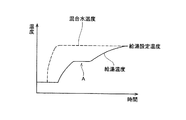
図6のグラフは、コールドスタート時の、ミキシングユニットの出口で測定した混合水温度(破線で示す)と、給湯栓から給湯される給湯温度(実線で示す)の推移を示している。混合水温度の温度上昇から遅れて、給湯温度が上昇する。給湯開始時に、混合水温度は迅速に上昇するが、給湯温度は、ミキシングユニットと給湯栓との間の冷えた配管や加熱器の熱交換器内に滞留している低温水等に熱を奪われ、図示Aのように温度上昇が停滞する。混合水温度が給湯設定温度まで上昇していても、給湯温度は給湯設定温度にまでなかなか上昇せず、立ち上がり時間が長くなってしまう。 The graph of FIG. 6 shows the transition of the mixed water temperature (shown by a broken line) measured at the outlet of the mixing unit and the hot water temperature supplied from the hot water tap (shown by a solid line) at the cold start. The hot water supply temperature rises after the temperature rise of the mixed water temperature. At the start of hot water supply, the temperature of the mixed water rises quickly, but the hot water supply temperature is deprived of heat from the cold piping between the mixing unit and the hot water tap or the low-temperature water staying in the heat exchanger of the heater. As shown in the figure A, the temperature rise is stagnant. Even if the mixed water temperature has risen to the hot water supply set temperature, the hot water supply temperature does not readily rise to the hot water supply set temperature, and the rise time becomes long.
特許文献1の技術では、貯湯槽の出口近傍に給湯配管を加熱する加熱手段を設けて加熱し、貯湯槽内の温水を利用して給湯する場合のコールドスタート時の立ち上がり時間を短縮する。しかし、別途加熱手段を設ける必要があることから、システムの製造コストをアップさせてしまう。
In the technique of
本発明では、貯湯槽からの温水を利用して給湯するコールドスタート時の立ち上がり時間を短縮することができるとともに、安価に製造することができる給湯システムを提供することを目的としている。 An object of the present invention is to provide a hot water supply system that can shorten the rise time at the time of cold start to supply hot water using hot water from a hot water tank and can be manufactured at low cost.
本発明の給湯システムは、温水を貯える貯湯槽と、貯湯槽からの温水と水道水を混合するとともにその混合比が調整可能なミキシングユニットと、ミキシングユニットより上流の温水温度を検出する温水温度検出手段と、ミキシングユニットより下流の混合水温度を検出する混合水温度検出手段と、給湯設定温度を記憶している給湯設定温度記憶手段と、ミキシングユニットに混合水温度を指示する混合水温度指示手段と、混合水の流動開始後の混合水流量を積算する混合水流量積算手段を備えている。
本発明の混合水温度指示手段は、混合水温度検出手段によって検出される混合水温度が第1所定温度以下であり、温水温度検出手段によって検出される温水温度が第2所定温度以上であり、混合水流量積算手段によって積算された積算流量が所定積算流量以下であるときには、給湯設定温度より所定温度だけ高い混合水温度を指示し、積算流量が前記した所定積算流量以上であるときには、給湯設定温度を指示する。
The hot water supply system of the present invention includes a hot water storage tank for storing hot water, a mixing unit that mixes hot water from the hot water storage tank and tap water, and an adjustable mixing ratio, and hot water temperature detection that detects the temperature of the hot water upstream from the mixing unit. Means, a mixed water temperature detecting means for detecting a mixed water temperature downstream from the mixing unit, a hot water supply temperature storing means for storing a hot water supply set temperature, and a mixed water temperature indicating means for instructing the mixing water temperature to the mixing unit And a mixed water flow rate integration means for integrating the mixed water flow rate after starting the flow of the mixed water.
The mixed water temperature indicating means of the present invention is such that the mixed water temperature detected by the mixed water temperature detecting means is not higher than the first predetermined temperature, and the hot water temperature detected by the hot water temperature detecting means is not lower than the second predetermined temperature, When the integrated flow integrated by the mixed water flow integration means is less than or equal to the predetermined integrated flow, a mixed water temperature higher by a predetermined temperature than the hot water supply set temperature is indicated, and when the integrated flow is above the predetermined integrated flow, the hot water supply setting Indicate the temperature.
この発明では、ミキシングユニットより下流の混合水温度が第1所定温度(例えば、実施例で例示するような25℃)以下であると、コールドスタートであると判別する。またミキシングユニットより上流の温水温度が第2所定温度(通常は給湯設定温度)以上であると、貯湯槽内の温水を利用することによって加熱しないで給湯可能であると判別する。コールドスタートであり、且つ貯湯槽内の温水を利用して加熱しないで給湯するときには、ミキシングユニットに給湯設定温度より所定温度だけ高い混合水温度を指示する。加熱器で加熱しないコールドスタート時には、ミキシングユニットで給湯設定温度より高い温度で調温することによって、給湯配管内温度の上昇速度を速めることができる。給湯配管内温度が速く上昇すれば、混合水が給湯配管内を通過するときの放熱ロスが抑制されるため、給湯栓から給湯される温水温度の上昇速度を速めることができる。このことから、加熱器で加熱しないコールドスタート時の立ち上がり時間を短縮することが可能となる。
混合水の積算流量が所定積算流量に達したら、ミキシングユニットに給湯設定温度を指示する。給湯設定温度より高温に調温された混合水が給湯箇所から給湯され始める前に、ミキシングユニットから送り出される混合水の温度が給湯設定温度に切換えられるため、給湯設定温度より高温の温水が給湯箇所から給湯されることを防止することができる。
In the present invention, when the temperature of the mixed water downstream from the mixing unit is equal to or lower than a first predetermined temperature (for example, 25 ° C. as exemplified in the embodiment), it is determined that the cold start has occurred. If the temperature of the hot water upstream from the mixing unit is equal to or higher than the second predetermined temperature (usually a hot water supply set temperature), it is determined that the hot water can be supplied without heating by using the hot water in the hot water storage tank. When it is a cold start and hot water is supplied without using the hot water in the hot water tank, the mixing water temperature is instructed to the mixing unit by a predetermined temperature higher than the hot water supply set temperature. During a cold start that is not heated by the heater, the temperature of the hot water supply pipe can be increased by adjusting the temperature at a temperature higher than the hot water supply set temperature by the mixing unit. If the temperature in the hot water supply pipe rises quickly, the heat dissipation loss when the mixed water passes through the hot water supply pipe is suppressed, so that the rising speed of the hot water temperature supplied from the hot water tap can be increased. From this, it becomes possible to shorten the rise time at the time of cold start which is not heated by the heater.
When the integrated flow rate of the mixed water reaches a predetermined integrated flow rate, the hot water supply set temperature is instructed to the mixing unit. Before the mixed water adjusted to a temperature higher than the hot water supply set temperature begins to be supplied from the hot water supply point, the temperature of the mixed water delivered from the mixing unit is switched to the hot water set temperature, so hot water higher than the hot water set temperature is It is possible to prevent the hot water from being fed from.
本発明の別の給湯システムでは、混合水温度指示手段が、前記混合水温度検出手段によって検出される混合水温度が第1所定温度以下であり、前記温水温度検出手段によって検出される温水温度が第2所定温度以上であるときには、給湯設定温度より所定温度だけ高い混合水温度を指示し、混合水温度検出手段によって検出される混合水温度が給湯設定温度より所定温度だけ高い温度となった時以降には、給湯設定温度に加える温度を徐々にゼロにまで縮小する。 In another hot water supply system of the present invention, the mixed water temperature indicating means is such that the mixed water temperature detected by the mixed water temperature detecting means is equal to or lower than a first predetermined temperature, and the hot water temperature detected by the hot water temperature detecting means is When the temperature is equal to or higher than the second predetermined temperature, a mixed water temperature higher by a predetermined temperature than the hot water supply set temperature is instructed, and when the mixed water temperature detected by the mixed water temperature detection means becomes a temperature higher by a predetermined temperature than the hot water supply set temperature Thereafter, the temperature applied to the hot water supply set temperature is gradually reduced to zero.
この発明でも、ミキシングユニットより下流の混合水温度が第1所定温度以下であるとにはコールドスタートであると判別する。またミキシングユニットより上流の温水温度が第2所定温度以上であると、貯湯槽内の温水を利用することによって加熱しないで給湯可能であると判別する。コールドスタートであり、且つ貯湯槽内の温水を利用して加熱しないで給湯するときには、ミキシングユニットに給湯設定温度より所定温度だけ高い混合水温度を指示する。加熱器で加熱しないコールドスタート時には、ミキシングユニットで給湯設定温度より高い温度で調温することによって、給湯配管内温度の上昇速度を速めることができる。給湯配管内温度が速く上昇すれば、混合水が給湯配管内を通過するときの放熱ロスが抑制されるため、給湯栓から給湯される温水温度の上昇速度を速めることができる。加熱器で加熱しないコールドスタート時の立ち上がり時間を短縮することが可能となる。
本発明では、混合水温度検出手段によって検出される混合水温度が給湯設定温度より所定温度だけ高い温度となった時以降には、給湯設定温度に加える温度を徐々にゼロにまで縮小する。
ミキシングユニットで混合された混合水温度が給湯設定温度より所定温度だけ高い温度に達すれば、ミキシングユニットより下流の配管内温度も上昇している。従って、この時点以降にミキシングユニットから送り出される混合水温度を徐々に低下させていっても、給湯箇所で給湯される温水温度が給湯設定温度まで上昇する時間を長くしない。ミキシングユニットから送り出される混合水温度を徐々に低下させていくために、給湯栓から給湯される温水温度が急激に変動することを防止することができる。
Also in this invention, when the temperature of the mixed water downstream from the mixing unit is equal to or lower than the first predetermined temperature, it is determined that the cold start has occurred. If the hot water temperature upstream from the mixing unit is equal to or higher than the second predetermined temperature, it is determined that hot water can be supplied without heating by using the hot water in the hot water storage tank. When it is a cold start and hot water is supplied without using the hot water in the hot water tank, the mixing water temperature is instructed to the mixing unit by a predetermined temperature higher than the hot water supply set temperature. During a cold start that is not heated by the heater, the temperature of the hot water supply pipe can be increased by adjusting the temperature at a temperature higher than the hot water supply set temperature by the mixing unit. If the temperature in the hot water supply pipe rises quickly, the heat dissipation loss when the mixed water passes through the hot water supply pipe is suppressed, so that the rising speed of the hot water temperature supplied from the hot water tap can be increased. It is possible to shorten the rise time at the cold start when the heater is not heated.
In the present invention, after the mixed water temperature detected by the mixed water temperature detecting means becomes a temperature higher than the hot water supply set temperature by a predetermined temperature, the temperature applied to the hot water supply set temperature is gradually reduced to zero.
If the temperature of the mixed water mixed in the mixing unit reaches a temperature that is higher than the preset hot water supply temperature by a predetermined temperature, the temperature in the pipe downstream from the mixing unit also increases. Therefore, even if the temperature of the mixed water sent out from the mixing unit is gradually lowered after this time, the time for the hot water temperature to be supplied at the hot water supply point to rise to the hot water supply set temperature is not lengthened. Since the temperature of the mixed water sent out from the mixing unit is gradually lowered, it is possible to prevent the temperature of the hot water supplied from the hot water tap from fluctuating rapidly.
本発明の給湯システムでは、コールドスタート時に給湯設定温度に加える温度を、給湯設定温度と混合水温度検出手段で検出する混合水温度との温度差によって決定することが好ましい。
ミキシングユニットの下流側温度がそれほど低くないときに、ミキシングユニットより下流の配管内温度の上昇速度が速すぎると、給湯設定温度より高温の温水が給湯されてしまうことがある。一方、下流側温度がかなり低いときに、ミキシングユニットより下流の配管内温度の上昇速度が遅すぎると、立ち上がり時間が長く掛かってしまうことがある。下流側温度が高いほど給湯設定温度に加える温度を小さくし、下流側温度が低いほど給湯設定温度に加える温度を大きくすることによって、ミキシングユニットより下流の配管内温度の上昇速度を適切に調整することができ、立ち上がりに要する時間を短縮しながら給湯温度の変化を抑制することができる。
In the hot water supply system of the present invention, it is preferable that the temperature added to the hot water supply set temperature at the cold start is determined by the temperature difference between the hot water supply set temperature and the mixed water temperature detected by the mixed water temperature detecting means.
When the temperature on the downstream side of the mixing unit is not so low and the rising speed of the temperature in the pipe downstream from the mixing unit is too high, hot water having a temperature higher than the hot water supply set temperature may be supplied. On the other hand, when the temperature on the downstream side is considerably low, if the rising speed of the temperature in the pipe downstream from the mixing unit is too slow, the rise time may take a long time. The temperature added to the hot water supply set temperature is decreased as the downstream temperature is higher, and the temperature added to the hot water set temperature is increased as the downstream temperature is lower, thereby appropriately adjusting the rate of increase in the temperature in the pipe downstream from the mixing unit. It is possible to suppress the change in the hot water supply temperature while shortening the time required for starting up.
以下、本発明の好適な実施形態を説明する。
(形態1) ミキシングユニットの下流に設置されているセンサが検出する温度と給湯器の下流に設置されているセンサが検出する温度の双方が第1所定温度以下であるときに、コールドスタートであると判定する。
(形態2) 第2所定温度は、給湯設定温度より所定温度だけ高い温度である。
(形態3) 混合水温度について多段階の温度領域が設定されており、それぞれの混合水温度の温度領域に対して給湯設定温度に加える温度が段階的に設定されている。
(形態4) 所定積算流量は、ミキシングユニットより下流の配管容量(切換準備流量)である。
(形態5) 積算流量が切換準備流量に達するときに給湯設定温度に加える温度がゼロとなるように、給湯設定温度に加える温度を段階的に減少させる。
Hereinafter, preferred embodiments of the present invention will be described.
(Mode 1) A cold start occurs when both the temperature detected by the sensor installed downstream of the mixing unit and the temperature detected by the sensor installed downstream of the water heater are equal to or lower than the first predetermined temperature. Is determined.
(Mode 2) The second predetermined temperature is a temperature that is higher than the preset hot water supply temperature by a predetermined temperature.
(Mode 3) A multi-stage temperature range is set for the mixed water temperature, and the temperature to be added to the hot water supply set temperature is set stepwise for each temperature range of the mixed water temperature.
(Mode 4) The predetermined integrated flow rate is a pipe capacity (switching preparation flow rate) downstream from the mixing unit.
(Mode 5) The temperature applied to the hot water supply set temperature is decreased stepwise so that the temperature applied to the hot water supply set temperature becomes zero when the integrated flow rate reaches the switching preparation flow rate.
(実施例1)
本発明の給湯システムを具現化した第1実施例を図面を参照しながら説明する。本実施例は、本発明の給湯システムを組込んだコージェネレーションシステムである。
本実施例のコージェネレーションシステムは、図1に示すように、発電ユニット110と給湯システム10等を備えている。
発電ユニット110は、改質器112、燃料電池114、熱交換器116、118、熱媒放熱器120、熱媒三方弁122、それらを接続する経路等を備えている。
改質器112には、バーナ131が設けられている。バーナ131が作動して熱を発生すると、改質器112は炭化水素系のガスから水素ガスを生成する。バーナ131で燃焼した高温の燃焼ガスは燃焼ガス経路126に導かれる。燃焼ガス経路126は、改質器112から熱交換器116を通過して外部に開放されている。熱交換器116には、循環経路128も通過している。燃焼ガス経路126は、バーナ131で発生した高温の燃焼ガスを熱交換器116に導き、循環経路128を流れる水を加熱し、熱交換によって温度が低下した燃焼ガスを外部に排出する。
循環経路128は、循環復路128aと、循環往路128bから構成されており、給湯システム10と接続されている。循環経路128が給湯システム10にどのように接続されているのかについては、後で詳細に説明する。循環経路128は温水を流通させる。循環経路128を流れる温水は、熱交換器116を通過することによって燃焼ガス経路126を流れる燃焼ガスによって加熱され、温度が上昇する。
Example 1
A first embodiment embodying a hot water supply system of the present invention will be described with reference to the drawings. A present Example is a cogeneration system incorporating the hot-water supply system of this invention.
As shown in FIG. 1, the cogeneration system of the present embodiment includes a
The
The
The
燃料電池114は複数のセルを有している。燃料電池114と改質器112は水素ガス供給経路121によって接続されている。改質器114で生成された水素ガスは、水素ガス供給経路121を流れて燃料電池114に供給される。燃料電池114は、改質器112から供給された水素ガスと、空気中の酸素とを反応させて発電を行なう。燃料電池114は発電すると発電熱を発生する。
熱媒循環経路124は、燃料電池114、熱交換器118、リザーブタンク125、熱媒ポンプ127、熱媒三方弁122を通って燃料電池114に戻る循環経路を形成している。熱媒循環経路124の燃料電池114の下流側には、熱媒温度センサ117が装着されている。熱媒温度センサ117は、熱媒循環経路124を流れる熱媒の温度を検出する。熱媒温度センサ117の検出信号は、給湯システム10に装着されているコントローラ21に出力される。
熱媒三方弁122は、1つの入口122aと、2つの出口122b,122cを備えている。熱媒三方弁122は、入口122aと出口122bを連通させるか、入口122aと出口122cを連通させるかを切換える。
熱媒三方弁122の出口122bと、熱媒循環経路124の熱媒三方弁122の出口122cの下流側とを接続する冷却経路129が設けられている。熱媒循環経路124と冷却経路129は熱媒としての純水を流通させる。冷却経路129の途中には熱媒放熱器120が装着されている。熱媒放熱器120に隣接して熱媒冷却ファン119が設けられている。熱媒冷却ファン119を運転すると、空気が熱媒放熱器120に吹付けられ、冷却経路129を流れる熱媒が冷却される。
改質器112、燃料電池114、バーナ131、熱媒三方弁122、熱媒ポンプ127、熱媒冷却ファン119は、コントローラ21によって制御される。
The
The heat medium circulation path 124 forms a circulation path that returns to the
The heat medium three-
A
The
燃料電池114が作動すると、熱媒三方弁122の入口122aと出口122cが連通されるとともに、熱媒ポンプ127が運転される。熱媒ポンプ127が運転されると、熱媒循環経路124を熱媒が循環する。熱媒循環経路124を熱媒が循環することにより、燃料電池114から発電熱が回収される。熱媒によって回収された発電熱は、熱媒とともに熱交換器118まで運ばれ、循環経路128を流れる温水を加熱する。循環経路128については後述する。
熱媒温度センサ117が検出した熱媒温度が高くなりすぎると、発電熱の回収が不十分となってしまうため、発電熱の放熱を行なう。熱媒三方弁122の入口122aと出口122bが連通され、同時に熱媒冷却ファン119が運転される。熱媒三方弁122の入口122aと出口122bが連通されると、熱媒は冷却経路129に流入し、熱媒放熱器120を通過する。熱媒は、熱媒放熱器120を通過することによって冷却される。熱媒放熱器120は、熱媒冷却ファン119から空気が吹付けられることにより、高い効率で熱を放熱する。熱媒の温度が低下すると、熱媒三方弁122の入口122aと出口122cが再び連通される。このような熱媒三方弁122の切換えが繰返されることにより、熱媒の温度は、所定範囲内に維持される。
When the
If the temperature of the heat medium detected by the heat
給湯システム10は、貯湯槽20、給湯器(加熱器)22、ミキシングユニット(混合器)24、これらを連通する複数の経路、コントローラ21等を備えている。
貯湯槽20の底部には、貯湯槽20に水道水を給水する給水経路26が接続されている。給水経路26の入口26aの近傍には、減圧弁28が装着されている。給水経路26の減圧弁28の下流側とミキシングユニット24の給水入口24aは、ミキシングユニット給水経路30によって接続されている。減圧弁28は、貯湯槽20とミキシングユニット24への給水圧力を調整する。貯湯槽20内の温水が減少したり、ミキシングユニット24の給水入口24aが開いたりすると、減圧弁28の下流側圧力が低下する。減圧弁28は、下流側圧力が低下すると開き、その圧力を所定の調圧値に維持しようとする。このため、貯湯槽20内の温水が減少したり、ミキシングユニット24の給水入口24aが開いたりすると、それらに水道水が給水される。
貯湯槽20には、調圧値に調圧された水が貯められる。貯湯槽20は、調圧値に耐えられる耐圧容器で形成されている。貯湯槽20の上部には出口部20aが設けられており、さらにその上にリリーフ弁31が装着されている。リリーフ弁31の開弁圧力は、減圧弁28の調圧値よりも僅かに大きく設定されている。減圧弁28の調圧が不能になった場合には、リリーフ弁31が開き、貯湯槽20内の圧力が耐圧圧力を超えるのを防止する。リリーフ弁31には、圧力開放経路32の一端32aが接続されている。圧力開放経路32の他端32bは貯湯槽20の外部に開放されている。
貯湯槽20の底部と、圧力開放経路32の他端32b近傍を接続する排水経路33が設けられている。排水経路33の途中には排水弁34が装着されている。排水弁34は手動で開閉することができる。排水弁34を開くと、貯湯槽20内の水が排水経路33と開放経路32を通って外部に排水される。
The hot
A
The hot
A
貯湯槽20は、発電ユニット110の循環経路128(循環復路128a、循環往路128b)と接続されている。詳しくは、循環復路128aが貯湯槽20の上部に接続され、循環往路128bが貯湯槽20の下部に接続されている。これによって、貯湯槽20と発電ユニット110との間の循環経路が形成されている。循環往路128bの途中には循環ポンプ40が装着されている。循環復路128aに復路サーミスタ45が取付けられ、循環往路128bに往路サーミスタ44が取付けられている。復路サーミスタ45は循環復路128a内の温水の温度を検出し、往路サーミスタ44は循環往路128b内の温水の温度を検出する。復路サーミスタ45と往路サーミスタ44の検出信号はコントローラ21に出力される。
循環ポンプ40が作動すると、貯湯槽20の底部から温水が吸出される。貯湯槽20から吸出された温水は、循環往路128bを流れてから発電ユニット110の熱交換器118、116を通過することによって加熱されて温度が上昇する。温度が上昇した温水は、循環復路128aを流れて貯湯槽20の上部に戻される。このように、貯湯槽20の底部から吸出された温水が、発電ユニット110の熱交換器118、116によって加熱されてさらに高温になり、貯湯槽20の上部に戻される循環が行われることにより、貯湯槽20に高温の温水が貯えられる。貯湯槽20内の温度が低い状態から、貯湯槽20に発電ユニット110からの高温の温水が戻されると、貯湯槽20の上部に高温の温水が戻されることから、冷水層の上部に高温層が積層した状態(以下、「温度成層」と言う)が形成される。高温層よりも深い部分の水の温度は急激に低下する。発電中に、貯湯槽20の底部から低温の温水が吸出され、上部に高温の温水が戻され続けると、高温層は低温層と交じり合うことなく、低温層の厚さ(深さ)は次第に小さくなり、高温層の厚さ(深さ)は次第に大きくなる。貯湯槽20にフルに蓄熱された状態では、貯湯槽20の全体に高温の温水が貯まった状態になる。温度成層が形成されることにより、貯湯槽20にフルに蓄熱が行われていなくても、貯湯槽20の最上部に設けられている出口部20aからは、高温の温水が送り出される。一方、貯湯槽20の温水が利用されると、貯湯槽20の上部の高温の温水が吸出され、底部から水道水が入水すると、高温層の厚さ(深さ)は次第に小さくなり、低温層の厚さ(深さ)は次第に大きくなる。貯湯槽20内の温水を使い切ると、貯湯槽20内は水道水で満たされた状態となる。
The
When the
コントローラ21は、CPU、ROM、RAM等を備えており、CPUがROMに格納されている制御プログラムを処理することによって、発電ユニット110と給湯システム10を制御する。RAMには、コントローラ21に入力される各種信号や、CPUが処理を実行する過程で生成される種々のデータが一時的に記憶される。コントローラ21にはリモコン23が接続されている。リモコン23には、発電ユニット110と給湯システム10を操作するためのスイッチやボタン、発電ユニット110と給湯システム10の動作状態を表示するとともに後記する運用方法を表示する液晶表示器等が設けられている。
The
貯湯槽20の上部から5リットルの箇所に上部サーミスタ35が取付けられている。上部サーミスタ35は貯湯槽20内の温度を検出する。上部サーミスタ35の検出信号は、コントローラ21に出力される。上部サーミスタ35の検出温度は、湯温制御に利用される他、蓄熱量の算出に利用される。算出される蓄熱量は、コントローラ21に用意されている記憶部に経時的に記憶される。
An
ミキシングユニット24は、温水入口24c、混合水出口24b、第1流量センサ67、温水サーミスタ50、給水サーミスタ48、混合水サーミスタ54、ハイカットサーミスタ55、および既に説明した給水入口24aを有している。貯湯槽20の出口部20aとミキシングユニット24の温水入口24cは、温水経路42によって接続されている。第1流量センサ67は、混合水出口24bから流出する混合水の流量を検出する。温水サーミスタ50は、温水入口24cに流入する温水の温度を検出する。給水サーミスタ48は、給水入口24aに流入する水道水の温度を検出する。混合水サーミスタ54とハイカットサーミスタ55は、混合水出口24bから流出する混合水の温度を検出する。第1流量センサ67、温水サーミスタ50、給水サーミスタ48、混合水サーミスタ54、ハイカットサーミスタ55の検出信号は、コントローラ21に出力される。
The mixing
コントローラ21は、混合水サーミスタ54の検出信号を用いて、温水入口24c側の開度と、給水入口24a側の開度を変化させる。温水入口24c側の開度と、給水入口24a側の開度を変化させると、貯湯槽20からの温水と、水道水(冷水)とのミキシング割合が調整される。貯湯槽20からの温水と水道水とのミキシング割合が調整されると、混合水出口24bから流出する温水の温度が所定値に維持される。
コントローラ21とミキシングユニット24を組合せて用いることによって、混合水サーミスタ54で計測される混合水の温度は、コントローラ21が指令する温度に調整される。
コントローラ21は、ハイカットサーミスタ55によって温水が前記所定値を大きくオーバーしたことが検出された場合(すなわち、混合水サーミスタ54、あるいはミキシングユニット24が故障した可能性が高い場合)に、温水入口24cを閉じる。温水入口24cが閉じると、前記所定値を大きくオーバーした温度の温水が、給湯器22に供給されてしまうのが防止される。
ミキシングユニット24の混合水出口24bと給湯器22のバーナ熱交換器52(後述する)は、温水経路51によって接続されている。温水経路51には、第2流量センサ47が装着されている。第2流量センサ47の検出信号は、コントローラ21に出力される。
The
By using the
When it is detected by the high-
The
給湯器22は、バーナ熱交換器52,60、バーナ56,57、追焚き熱交換器58、補給水弁59、シスターン61等を備えている。バーナ熱交換器52には、温水経路51を経由してミキシングユニット24から温水が流入する。ガス燃焼式のバーナ56はバーナ熱交換器52を加熱する。バーナ56は、コントローラ21から点火の指示を受けると、プリパージ動作を行った後に燃焼を開始する。プリパージに要する時間は、燃焼用ファンのサイズや回転数、バーナ56,57の燃焼ガスがバーナ熱交換器52,60を通過して装置外へ排気される部分の容量等から設定され、予めコントローラ21に記憶されている。プリパージには通常数秒を要し、本実施例のバーナ56では、プリパージに係る時間は1.5秒である。
バーナ熱交換器52の下流側と給湯栓64は給湯栓経路63によって接続されている。給湯栓64は、浴室、洗面所、台所等に配置されている(図1では、これら複数の給湯栓64を1つで代表している)。給湯栓経路63には給湯サーミスタ65が装着されている。給湯サーミスタ65はバーナ熱交換器52から流出する温水の温度を検出する。給湯サーミスタ65の検出信号はコントローラ21に出力される。
The
The downstream side of the burner heat exchanger 52 and the
温水経路51には、バーナ熱交換器52をバイパスするバイパス管37が形成されている。バイパス管37にはバイパスサーボ38が設けられている。バーナ熱交換器52にはバイパスサーボ38の開度はコントローラ21によって制御され、内蔵しているステッピングモータが駆動されることによって開度が調整される。バイパスサーボ38が開かれると、温水経路51のバーナ熱交換器52の上流側から分岐し、バイパス管37を通り、温水経路51のバーナ熱交換器52の下流側に合流するバイパス経路が形成される。コントローラ21によってバイパスサーボ38の開度を制御することによって、バーナ熱交換器52への流量に対するバイパス管37への流量の割合であるバイパス比が制御される。
A
給湯器22内の温水経路51の途中から、シスターン入水経路62が分岐している。シスターン入水経路62の開放端はシスターン61の上部に差し込まれている。シスターン入水経路62の途中には補給水弁59が設けられている。補給水弁59はコントローラ21によって制御され、内蔵しているソレノイドが駆動されることによって開閉する。補給水弁59が開かれると、ミキシングユニット24からの温水がシスターン61に供給される。
シスターン61内には水位電極66が装着されている。水位電極66は、棒状のハイレベルスイッチ66aとローレベルスイッチ66bを有している。ハイレベルスイッチ66aの下端はシスターン61のハイレベル水位に位置している。ローレベルスイッチ66bの下端はシスターン61のローレベル水位に位置している。ハイレベルスイッチ66aとローレベルスイッチ66bは、水に触れていると検出信号をコントローラ21に出力する。コントローラ21は、水位電極66からの検出信号によって、シスターン61の水位がハイレベル水位を超えているか、ハイレベル水位とローレベル水位の間にあるか、ローレベル水位よりも低いかを判別する。シスターン61として適正なのは、水位がハイレベルとローレベルの間に位置している状態である。コントローラ21は、水位電極66からの水位検出信号に基づいて補給水弁59を開閉制御し、シスターン61の水位を適正範囲に維持する。
From the middle of the
A
シスターン61の底部には、シスターン出水経路68の一端が接続されている。シスターン出水経路68の途中には暖房ポンプ69が装着されている。暖房ポンプ69はコントローラ21によって制御される。シスターン出水経路68の他端はバーナ上流経路71と低温水経路70とに分岐している。バーナ上流経路71はシスターン出水経路68とバーナ熱交換器60の上流側とを接続している。バーナ上流経路71には、内部を流れる温水の温度を検出する暖房低温サーミスタ72が装着されている。暖房低温サーミスタ72の検出信号はコントローラ21に出力される。
ガス燃焼式のバーナ57はバーナ熱交換器60を加熱する。バーナ熱交換器60の下流とシスターン61は高温水経路73によって接続されている。高温水経路73には、上流側から順に、暖房高温サーミスタ74、暖房端末熱動弁75、暖房端末機76が装着されている。
暖房高温サーミスタ74は、高温水経路73を流れる温水の温度を検出する。暖房高温サーミスタ74の検出信号はコントローラ21に出力される。
One end of a cistern
The gas
The heating
暖房端末機76は、熱交換器76bと、操作スイッチ76aと、電動ファン(図示省略)を備えている。熱交換器76bは、高温水経路73を流れる温水と空気との間で熱交換を行なう。操作スイッチ76aは暖房端末熱動弁75とコントローラ21に接続されている。
暖房端末熱動弁75は、膨張エレメントと、膨張エレメントと機械的に連結された開閉弁を内蔵している。暖房端末機76の操作スイッチ76aがオンにされると、暖房端末熱動弁75の膨張エレメントに通電が行われる。通電された膨張エレメントは高温になって膨張する。膨張した膨張エレメントは開閉弁を駆動し、これによって暖房端末熱動弁75が開かれる。また、操作スイッチ76aがオンにされると、コントローラ21は、暖房ポンプ69を作動させる。このように、操作スイッチ76aがオンにされたことによって、暖房端末熱動弁75が開かれるとともに、暖房ポンプ69が作動すると、シスターン61から温水が吸出される。コントローラ21は、暖房低温サーミスタ72と暖房高温サーミスタ74が検出した温水温度に基づいて、バーナ57を制御し、バーナ熱交換器60から流出する温水の温度を所定範囲に維持する。暖房端末機76の電動ファンは、操作スイッチ76aがオンにされると回転し、熱交換器76bに空気を吹付ける。熱交換器76bに吹付けられた空気は、熱交換器76bを介して温水と熱交換を行って暖められる。暖められた空気は暖房端末機76から吹出し、部屋を暖房する。熱交換器76bで空気と熱交換を行なうことによって、温水の温度は低下する。温度が低下した温水は高温水経路73を流れてシスターン61に戻る。
The
The heating terminal thermal valve 75 includes an expansion element and an on-off valve mechanically connected to the expansion element. When the
高温水経路73の暖房高温サーミスタ74の下流側と、高温水経路73のシスターン61への入口部の上流側とは追焚き経路77によって接続されている。追焚き経路77は追焚き熱交換器58を通過している。追焚き経路77の追焚き熱交換器58の上流側には追焚き熱動弁78が装着されている。追焚き熱動弁78はコントローラ21によって制御される。
浴槽79には吸出口79aと供給口79bが設けられている。吸出口79aと供給口79bは風呂循環経路80によって接続されている。風呂循環経路80は追焚き熱交換器58を通過している。上述したように、追焚き経路77も追焚き熱交換器58を通過している。このため、追焚き熱交換器58では、風呂循環経路80と追焚き経路77との間で熱交換が行われる。風呂循環経路80の追焚き熱交換器58の上流側には、風呂水位センサ81、風呂循環ポンプ82、風呂水流スイッチ84が装着されている。風呂循環ポンプ82はコントローラ21によって制御される。風呂水位センサ81、風呂水流スイッチ84は、コントローラ21に検出信号を出力する。風呂水位センサ81は水圧を検出する。コントローラ21は、風呂水位センサ81が検出した水圧から、浴槽79に張られている湯の水位を推定する。風呂水流スイッチ84は風呂循環経路80を水が流れるとオンになる。
風呂循環経路80の風呂水位センサ81の上流側には、浴槽79から吸出された温水の温度を検出する風呂サーミスタ85が装着されている。風呂サーミスタ85の検出信号はコントローラ21に出力される。
The downstream side of the heating
The
On the upstream side of the bath
バーナ57と暖房ポンプ69が作動している状態で追焚き熱動弁78が開くと、温水が追焚き経路77に流入して追焚き熱交換器58を通過する。風呂循環ポンプ82が作動すると、温水が浴槽79の吸出口79aから吸出され、風呂循環経路80を流れて再び供給口79bから浴槽79に戻る循環が行われる。風呂循環経路80を流れる温水は、追焚き熱交換器58で追焚き経路77を流れる温水によって加熱され、浴槽79の湯が追焚きされる。
When the reheating
給湯栓経路63の途中と、風呂循環経路80の風呂循環ポンプ82の下流側とを接続する湯張り経路25が設けられている。湯張り経路25には、ソレノイド駆動タイプの注湯弁27と、湯張り量センサ83が装着されている。注湯弁27は、コントローラ21によって制御され、湯張り経路25を開閉する。湯張り量センサ83は、湯張り経路25を流れる水量を検出することにより、浴槽79への湯張り運転の際に、それがどの程度行われたかを推定する。湯張り量センサ83はコントローラ21に検出信号を出力する。
浴槽79に湯を張るときには、注湯弁27が開かれる。注湯弁27が開かれると、温水が給湯栓経路63から湯張り経路25を経て風呂循環経路80に流入する。風呂循環経路80に流入した温水は、吸出口79aと供給口79bから浴槽79に供給され、浴槽79に湯張りされる。このときには、風呂循環ポンプ82は駆動されず、湯張り経路25に加わっている水圧によって浴槽79への湯張り運転が行われる。
A hot
When hot water is filled in the
低温水経路70の途中には、低温サーミスタ94、床暖房熱動弁90、床暖房機91が設けられている。床暖房機91は、低温水経路70を流れる温水によって床を暖める。床暖房を行なう場合には、床暖房熱動弁90が開かれ、温水が床暖房機91に導かれる。導かれた温水は、床暖房機91を暖める。床暖房を行なわない場合には、床暖房熱動弁90が閉じられる。低温サーミスタ94は、低温水経路70を流れる温水の温度を検出する。低温サーミスタ94の検出信号はコントローラ21に出力される。床暖房熱動弁90はコントローラ21によって制御される。
高温水経路73の暖房端末熱動弁75の上流側と、低温水経路70の床暖房機91の下流側とは、バイパス経路92によって接続されている。暖房端末熱動弁75と床暖房熱動弁90が閉じた状態で、暖房ポンプ69が作動すると、シスターン61内の温水が順に、バーナ上流経路71、バーナ熱交換器60、高温水経路73、バイパス経路92、低温水経路70、高温水経路73と流れ、シスターン61へ戻る経路が形成される。
In the middle of the low-
The upstream side of the heating terminal thermal valve 75 in the high
本実施例のコージェネレーションシステムでは、発電ユニット110において発電時に発生する発電熱を利用して水を加熱して貯湯し、貯湯しておいた温水を必要な時に利用することができる。温水が貯湯されていないときや貯湯されている温水の温度が低い場合、給湯器22のバーナ56,60によって加熱して利用する。
給湯停止後の給湯経路の配管および配管内の温水は、時間の経過とともに温度低下する。次の給湯までにある程度以上の時間が経過すれば温度低下し、給湯を再開してもすぐには給湯設定温度に調温された温水が出湯せず、低温水が出水する(コールドスタートという)。
本明細書では、給湯を開始してから給湯設定温度に調温された温水が給湯されるまでの状態を「立ち上がり」といい、給湯設定温度に調温された温水が給湯される状態になることを「立ち上がる」ということがある。
In the cogeneration system according to the present embodiment, water is heated and stored using the generated heat generated during power generation in the
The temperature of the piping of the hot water supply path and the hot water in the piping after the hot water supply stops decreases with time. If a certain amount of time elapses before the next hot water supply, the temperature will drop, and even if hot water is resumed, the hot water adjusted to the hot water supply temperature will not come out immediately, and low-temperature water will come out (called cold start). .
In this specification, the state from the start of hot water supply until the hot water adjusted to the hot water set temperature is supplied is referred to as “rise”, and the hot water adjusted to the hot water set temperature is supplied. This is sometimes called “getting up”.
給湯器22のバーナ56で水道水を加熱して給湯する場合では、コールドスタート時、バーナ56で加熱された温水が出湯する前に、バーナ熱交換器52の下流側から給湯栓64までの配管容量分の低温水が出水する。また、バーナ56で加熱された温水は、給湯配管内を通過する間に、冷えた給湯配管に熱を奪われて温度低下する。従って、バーナ熱交換器52の下流側から給湯栓64までの配管容量分の低温水が出水した後も、給湯配管内温度が上昇するまでの間は、給湯設定温度に満たない温度の温水が出湯する。このコールドスタート時の現象は使用者に容認されており、給湯設定温度に調温された温水が給湯されるまでに(立ち上がるまでに)出水する低温水量や、立ち上がりに要する時間(立ち上がり時間ともいう)については、ある程度使用者に了承されている。
When the tap water is heated by the
貯湯槽20内の温水をバーナ56で加熱することなく利用して給湯する場合、即ち蓄熱を利用して給湯する場合では、コールドスタート時、ミキシングユニット24で調温された混合水が出湯する前に、貯湯槽20から給湯栓64までの配管容量分の低温水が出水する。このとき出水する低温水の量は、給湯器22を利用して給湯するときと比べると、貯湯槽20からバーナ熱交換器52の下流側までの配管容量分多い。また、調温後の混合水の給湯経路は、給湯器22を利用して給湯する場合、バーナ熱交換器52の下流側から給湯栓64までであるのに対し、蓄熱を利用して給湯する場合、ミキシングユニット22から給湯栓64までである。調温後の混合水の給湯経路は、蓄熱を利用して給湯する場合、給湯器を利用して給湯する場合に比べ、ミキシングユニット22からバーナ熱交換器52の下流側までの配管長さ分だけ長い。また、ミキシングユニット22から給湯栓64までの間にはバーナ熱交換器52があり、バーナ熱交換器52内には低温水が滞留している。蓄熱を利用して給湯する場合、給湯器22を利用して給湯する場合に比べて、コールドスタート時に冷えた給湯配管や、バーナ熱交換器52内に滞留している低温水に奪われる熱量が多くなり、放熱ロスも大きくなってしまう。
When hot water is supplied without using the hot water in the hot
本実施例のコージェネレーションシステムでは、給湯経路である温水経路51に、バーナ熱交換器52をバイパスするバイパス管37が形成されており、バイパス管37にはバイパスサーボ38が設けられている。仮に、給湯器22を利用していないときに限り、バイパスサーボ38の開度を調節し、バイパス管37側を全開としてバーナ熱交換器52側を全閉とすれば、コールドスタート時に、バーナ熱交換器52内に滞留している低温水に熱を奪われることはなくなる。しかしながら、バーナ熱交換器52側が全閉である状態で、万が一バーナ56が着火してしまうようなことがあれば、バーナ熱交換器52部分が空焚き状態となってしまう。このため、本実施例のコージェネレーションシステムでは、安全面を考慮して、バーナ熱交換器52側を全閉とする制御は行なわない。
In the cogeneration system of the present embodiment, a
本実施例のコージェネレーションシステムでは、以下のように給湯温度制御を行なうことによって、蓄熱を利用して給湯する場合のコールドスタート時の立ち上がり時間を短縮している。
図2に示すように、ステップS10で第2流量センサ47が検出する流量が2.7リットル/min以上であるか否かが判別される。第2流量センサ47が検出する流量が2.7リットル/min以上となると(ステップS10でYESとなると)、給湯要求があったものとみなし、ステップS12に進む。ステップS12では、第2流量センサ47が検出する流量の積算を開始する。
ステップS14に進み、ミキシングユニット24の下流側の混合水サーミスタ54が検出する温度が25℃以下か否かが判別される。混合水サーミスタの検出温度が25℃以下であれば(ステップS14でYESであれば)、さらにステップS16に進み、バーナ熱交換器52の下流側の給湯サーミスタ65が検出する温度が25℃以下か否かが判別される。給湯サーミスタの検出温度が25℃以下であれば(ステップS16でYESであれば)、ステップS18に進む。混合水サーミスタの検出温度と給湯サーミスタの検出温度がいずれも25℃以下であるとき、コールドスタートであるとみなし、ステップS18に進む。
In the cogeneration system of the present embodiment, the rise time at the cold start when the hot water is supplied using the heat storage is shortened by performing the hot water supply temperature control as follows.
As shown in FIG. 2, it is determined in step S10 whether the flow rate detected by the second
In step S14, it is determined whether or not the temperature detected by the
コールドスタート時は、ミキシングユニット24より下流側の給湯配管および給湯配管内の温水の温度が低温であるほど、冷えた給湯配管に奪われる熱量が多くなるため、給湯設定温度に調温された温水が出湯するまでに時間が掛る。蓄熱を利用して給湯する場合、給湯経路が貯湯槽20から給湯栓64まであって長いため、この現象が特に顕著となる。
本実施例では、蓄熱を利用して給湯する場合、ミキシングユニット24で調温する混合水温度を温度αだけ高めに行なうことによって、給湯経路の配管の温度を速やかに上昇させ、立ち上がり時間を短縮する。ステップS18では温度αを決定する。温度αは混合水サーミスタ54の検出温度によって決定される。ミキシングユニット24より下流側の給湯配管内の温水温度によって3段階の温度領域に分け、低い温度領域ほど温度αが高く設定されている。混合水サーミスタ54の検出温度が5℃以下であれば、αは15℃に設定されている。混合水サーミスタ54の検出温度が5℃を超えて15℃以下であれば、αは10℃に設定されている。混合水サーミスタ54の検出温度が15℃を超えて25℃以下であれば、αは5℃に設定されている。給湯配管内の温水温度が低いときの温度αを大きくすることによって、冷えた給湯配管の温度をより早く上昇させることができる。給湯配管内の温水温度があまり低くないときの温度αを小さくすることによって、給湯配管内温度の上昇速度が速すぎて、ミキシングユニット24での温度制御に遅れが生じてしまい、給湯温度より高温の混合水が給湯されてしまうことを防止することができる。
At a cold start, the lower the temperature of hot water in the hot water supply pipe and the hot water supply pipe downstream from the mixing
In the present embodiment, when hot water is supplied using heat storage, the temperature of the mixed water adjusted by the mixing
ステップS20に進み、貯湯槽20の上部の温水温度を検出するための上部サーミスタ35が検出する温度が、給湯設定温度にα+1℃加えた温度以上であるか否かが判別される。このときの+1℃分は放熱分を考慮したものである。上部サーミスタ35の検出温度が〔給湯設定温度+α+1℃〕以上であれば(ステップS20でYESであれば)、貯湯槽20内の温水を給湯に利用できるとみなされ、ステップS22に進む。ステップS22では、ミキシングユニット24において、混合水サーミスタ54の検出温度が、〔給湯設定温度+α〕となるように、温水入口24cの開度と給水入口24aの開度が制御される。
ステップS24に進み、第2流量センサ47の検出流量の積算流量が切替準備流量に達したか否かが判別される。切替準備流量とは、ミキシングユニット24の下流側の混合水サーミスタ54からバーナ熱交換器52の下流側の給湯サーミスタ65までの間の配管容量である。第2流量センサ47の検出流量の積算流量が切替準備流量に達すれば(ステップS24でYESとなれば)、ミキシングユニット24で〔給湯設定温度+α〕に調温した混合水が、給湯サーミスタ65に到達したとみなされ、ステップS28に進む。ステップS24で、第2流量センサ47の検出流量の積算流量が切替準備流量に達する前であっても(NOであっても)、ステップS26において、給湯サーミスタ65の検出温度が給湯設定温度に達していれば(YESとなれば)、ステップS28に進む。ステップS28では、ミキシングユニット24において、混合水サーミスタ54の検出温度が給湯設定温度となるように、温水入口24cの開度と給水入口24aの開度が制御されて給湯される。以降、ステップS30で、第2流量センサ47が検出する流量が2.0リットル/min以下となって(YESとなって)給湯が停止されたとみなされるまで、混合水サーミスタ54の検出温度が給湯設定温度となるように調温された混合水が給湯される。
It progresses to step S20 and it is discriminate | determined whether the temperature which the
In step S24, it is determined whether or not the integrated flow rate detected by the second
ステップS20で、上部サーミスタ35の検出温度が、〔給湯設定温度+α+1℃〕を下回れば(NOであれば)、貯湯槽20内の温水温度が低く、給湯に利用することができないとみなされ、給湯器22を利用した給湯を行なう。ステップS32で、バーナ56を点火させ、ステップS34で、給湯サーミスタ65の検出温度が給湯設定温度となるように調温されて給湯される。以降、ステップS30で、第2流量センサ47が検出する流量が2.0リットル/min以下となって(YESとなって)給湯が停止されたとみなされるまで、給湯サーミスタ65の検出温度が給湯設定温度となるように調温された温水が給湯される。
In step S20, if the detected temperature of the
ステップS14で、混合水サーミスタ54の検出温度が25℃を上回っているか(NOであるか)、ステップS16で給湯サーミスタ65の検出温度が25℃を上回っていれば(NOであれば)、配管内温度が高めであり、ミキシングユニット24での調温の際に、温度α分高い温度で調温する必要がないとみなされる。従って、ステップS36に進み、上部サーミスタ35が検出する温度が、給湯設定温度に1℃加えた温度以上であるか否かが判別される。上部サーミスタ35の検出温度が〔給湯設定温度+1℃〕以上であれば(ステップS36でYESであれば)、貯湯槽20内の温水を給湯に利用できるとみなされ、ステップS38に進む。ステップS38では、ミキシングユニット24において、混合水サーミスタ54の検出温度が給湯設定温度となるように、温水入口24cの開度と給水入口24aの開度が制御されて給湯される。以降、ステップS30で、第2流量センサ47が検出する流量が2.0リットル/min以下となって(YESとなって)給湯が停止されたとみなされるまで、混合水サーミスタ54の検出温度が給湯設定温度となるように調温された混合水が給湯される。
If the detected temperature of the
ステップS36で、上部サーミスタ35の検出温度が〔給湯設定温度+1℃〕を下回れば(NOであれば)、貯湯槽20内の温水温度が低く、給湯に利用することができないとみなされ、給湯器22を利用した給湯を行なう。ステップS32で、バーナ56を点火させ、ステップS34で、給湯サーミスタ65の検出温度が給湯設定温度となるように調温されて給湯される。以降、ステップS30で、第2流量センサ47が検出する流量が2.0リットル/min以下となって(YESとなって)給湯が停止されたとみなされるまで、給湯サーミスタ65の検出温度が給湯設定温度となるように調温された温水が給湯される。
If the detected temperature of the
図6のグラフは、コールドスタート時に、従来通り、ミキシングユニット24において給湯設定温度で調温したときの混合水温度(破線で示す)と、給湯温度(実線で示す)の推移を示しており、図3のグラフは、本実施例のコージェネレーションシステムにおいて図2の湯温制御処理を行なったときの混合水温度(破線で示す)と、給湯温度(実線で示す)の推移を示している。給湯サーミスタ65は、混合水サーミスタ54より下流側にあるため、混合水サーミスタ54が検出する温度(混合水温度)の温度上昇から遅れて、給湯サーミスタ65が検出する温度(給湯温度)の温度上昇が起こる。
図6に示すように、ミキシングユニット24において給湯設定温度で調温したとき、給湯開始時の混合水温度は迅速に上昇するが、給湯栓64から給湯される給湯温度は、ミキシングユニット24と給湯栓64との間の給湯配管やバーナ熱交換器52内に滞留している低温水等に熱を奪われ、図示Aのように温度上昇が停滞する。混合水温度が給湯設定温度となっていても、給湯温度は給湯設定温度にまでなかなか上昇せず、立ち上がり時間が長くなって使用感が悪い。
The graph of FIG. 6 shows the transition of the mixed water temperature (shown by a broken line) and the hot water supply temperature (shown by a solid line) when the temperature is adjusted at the hot water supply set temperature in the mixing
As shown in FIG. 6, when the mixing
図3に示す時間t1は、給湯が開始されて、第2流量センサ47が検出する流量の積算が開始された時(図2のステップS12)を示しており、時間t2は、第2流量センサ47の検出流量の積算流量が切替準備流量に達した時(ステップS24でYES)を示している。図3に示すように、図2の湯温制御処理では、給湯開始時(時間t1)のミキシングユニット24での混合水温度を、給湯設定温度より温度α分高くしている(図3では、図の明瞭化のため、放熱を考慮した+1℃分の図示を省略している)。従って、給湯経路の配管内温度の上昇速度を速めることができる。給湯配管内温度が速く上昇すれば、混合水が給湯配管内を通過するときの放熱ロスが抑制されるため、給湯される混合水温度の上昇速度も速めることができる。第2流量センサ47の検出流量の積算流量が切替準備流量に達した時(時間t2)に、ミキシングユニット24で調温する混合水温度を給湯設定温度まで下げることによって、給湯温度が給湯設定温度を超えて温度上昇しないようにしている。このとき、既に給湯配管内温度は上昇しており、バーナ熱交換器52内の温度も上昇している。このため、時間t2でミキシングユニット24で調温する混合水温度を給湯設定温度に切換えても、給湯温度の温度上昇の妨げとはならない。
The time t1 shown in FIG. 3 indicates the time when hot water supply is started and the integration of the flow rate detected by the second
本実施例のコージェネレーションシステムによれば、コールドスタート時で給湯配管内が低温であって、しかも、蓄熱を利用して給湯するために給湯経路が長く放熱ロスが大きいときであっても、立ち上がり時間を短縮することができ、使い勝手を向上させることができる。 According to the cogeneration system of this embodiment, even when the hot water supply pipe is cold at the cold start and the hot water supply path is long and the heat dissipation loss is large to supply hot water using heat storage, Time can be shortened and usability can be improved.
(実施例2)
本発明を具現化した第2実施例を図面を参照しながら説明する。本実施例のコージェネレーションシステムの構成は第1実施例のコージェネレーションシステムの構成と同様である。本実施例でも第1実施例と同様に、ミキシングユニット24で調温する混合水温度を、給湯設定温度よりも高めで行なうことで、コールドスタート時の立ち上がり時間の短縮を図っている。しかし、本実施例では、給湯温度制御の一部の処理について第1実施例とは異なっている。ここでは、第1実施例と同様の部分についての説明を省略し、異なっている部分についてのみ説明する。
(Example 2)
A second embodiment embodying the present invention will be described with reference to the drawings. The configuration of the cogeneration system of the present embodiment is the same as the configuration of the cogeneration system of the first embodiment. In the present embodiment, similarly to the first embodiment, the mixed water temperature adjusted by the mixing
図4に示す、本実施例のコージェネレーションシステムの給湯温度制御では、ステップS110からステップS122の処理については、図2を用いて先に説明した、第1実施例のステップS10からステップS22の処理と同様であるため、説明を省略する。
ステップS122で混合水サーミスタ54の検出温度は徐々に上昇するように調温され、ステップS123で、混合水サーミスタ54の検出温度が〔給湯設定温度+α℃〕に達すれば(YESとなれば)、ステップS124に進む。
In the hot water supply temperature control of the cogeneration system of the present embodiment shown in FIG. 4, the processing from step S110 to step S122 is the processing from step S10 to step S22 of the first embodiment described above with reference to FIG. Since it is the same as that of FIG.
In step S122, the temperature of the
ステップS124では、第2流量センサ47の検出流量の積算流量が切替準備流量に近づくに従って温度αは小さくなり、第2流量センサ47の検出流量の積算流量が切替準備流量に達したとき、温度αは0℃となる。第2流量センサ47の検出流量の積算流量が切替準備流量に近づくに従って、混合水サーミスタ54の検出温度は徐々に低下し、第2流量センサ47の検出流量の積算流量が切替準備流量に達したとき、混合水サーミスタ54の検出温度は給湯設定温度となる。
ステップS125で、第2流量センサ47の検出流量の積算流量が切替準備流量に達したか否かが判別される。第2流量センサ47の検出流量の積算流量が切替準備流量に達したとき(ステップS125でYESとなったとき)、ミキシングユニット24で〔給湯設定温度+α〕に調温した混合水が、給湯サーミスタ65に到達したとみなされ、ステップS128に進む。ステップS125で、第2流量センサ47の検出流量の積算流量が切替準備流量に達する前であっても(NOであっても)、ステップS126において、給湯サーミスタ65の検出温度が給湯設定温度に達していれば(YESとなれば)、ステップS128に進む。ステップS128では、ミキシングユニット24において、混合水サーミスタ54の検出温度が給湯設定温度となるように、温水入口24cの開度と給水入口24aの開度が制御されて給湯される。以降、ステップS130で、第2流量センサ47が検出する流量が2.0リットル/min以下となって(YESとなって)給湯が停止されたとみなされるまで、混合水サーミスタ54の検出温度が給湯設定温度となるように調温された混合水が給湯される。
In step S124, the temperature α decreases as the integrated flow rate detected by the
In step S125, it is determined whether or not the integrated flow rate detected by the second
図5に示す時間t1は、給湯が開始されて、第2流量センサ47が検出する流量の積算が開始された時(図4のステップS112)を示しており、時間t2は、第2流量センサ47の検出流量の積算流量が切替準備流量に達した時(ステップS125でYES)を示している。また、時間t3は、混合水サーミスタ54の検出温度が〔給湯設定温度+α〕に達した時(図4のステップS123でYES)を示している。図5に示すように、図4の湯温制御処理では、図2の湯温制御処理と同様に、給湯開始時(時間t1)のミキシングユニット24で調温する混合水温度を、給湯設定温度より温度α分高くしている(図5でも、図の明瞭化のため、放熱を考慮した+1℃分の図示を省略している)。従って、給湯経路の配管内温度の上昇速度を速めることができる。混合水サーミスタ54の検出温度が〔給湯設定温度+α〕に達した時(時間t3)に、ミキシングユニット24で調温する混合水温度を徐々に下げ始め、第2流量センサ47の検出流量の積算流量が切替準備流量に達した時(時間t2)に、ミキシングユニット24で調温する混合水温度がちょうど給湯設定温度となるように温度低下させる。このことによって、給湯温度が給湯設定温度を超えて温度上昇しないようにしている。また、第1実施例のように、時間t2に、ミキシングユニット24で調温する混合水温度を一度に下げるのに比べ、給湯温度を安定化させることができる。時間t3では、既に給湯配管内温度は上昇しており、バーナ熱交換器52内の温度も上昇している。このため、時間t3から時間t2にかけてミキシングユニット24で調温する混合水温度を給湯設定温度まで徐々に低下させていっても、時間t3以降の給湯温度の温度上昇を遅くすることにはならない。
The time t1 shown in FIG. 5 indicates the time when hot water supply is started and the integration of the flow rate detected by the second
本実施例のコージェネレーションシステムによれば、コールドスタート時で給湯配管内が低温であって、しかも、蓄熱を利用して給湯するために給湯経路が長く放熱ロスが大きいときであっても、立ち上がり時間を短縮することができ、給湯温度を安定化させることができる。 According to the cogeneration system of this embodiment, even when the hot water supply pipe is cold at the cold start and the hot water supply path is long and the heat dissipation loss is large to supply hot water using heat storage, Time can be shortened and the hot water supply temperature can be stabilized.
以上、本発明の具体例を詳細に説明したが、これらは例示にすぎず、特許請求の範囲を限定するものではない。特許請求の範囲に記載の技術には、以上に例示した具体例を様々に変形、変更したものが含まれる。
また、本明細書または図面に説明した技術要素は、単独であるいは各種の組み合わせによって技術的有用性を発揮するものであり、出願時請求項記載の組み合わせに限定されるものではない。また、本明細書または図面に例示した技術は複数目的を同時に達成するものであり、そのうちの一つの目的を達成すること自体で技術的有用性を持つものである。
Specific examples of the present invention have been described in detail above, but these are merely examples and do not limit the scope of the claims. The technology described in the claims includes various modifications and changes of the specific examples illustrated above.
In addition, the technical elements described in the present specification or the drawings exhibit technical usefulness alone or in various combinations, and are not limited to the combinations described in the claims at the time of filing. In addition, the technology illustrated in the present specification or the drawings achieves a plurality of objects at the same time, and has technical utility by achieving one of the objects.
10:給湯システム
20:貯湯槽
22:給湯器
24:ミキシングユニット
35:上部サーミスタ
47:第2流量センサ
54:混合水サーミスタ
65:給湯サーミスタ
110:発電ユニット
10: Hot water supply system 20: Hot water storage tank 22: Water heater 24: Mixing unit 35: Upper thermistor 47: Second flow sensor 54: Mixed water thermistor 65: Hot water thermistor 110: Power generation unit
Claims (3)
貯湯槽からの温水と水道水を混合するとともにその混合比が調整可能なミキシングユニットと、
ミキシングユニットより上流の温水温度を検出する温水温度検出手段と、
ミキシングユニットより下流の混合水温度を検出する混合水温度検出手段と、
給湯設定温度を記憶している給湯設定温度記憶手段と、
ミキシングユニットに混合水温度を指示する混合水温度指示手段と、
混合水の流動開始後の混合水流量を積算する混合水流量積算手段を備え、
混合水温度指示手段は、前記混合水温度検出手段によって検出される混合水温度が第1所定温度以下であり、前記温水温度検出手段によって検出される温水温度が第2所定温度以上であり、前記混合水流量積算手段によって積算された積算流量が所定積算流量以下であるときには、給湯設定温度より所定温度だけ高い混合水温度を指示し、前記積算流量が前記所定積算流量以上であるときには、給湯設定温度を指示することを特徴とする給湯システム。 A hot water tank for storing hot water,
A mixing unit that mixes hot water and tap water from a hot water tank and adjusts the mixing ratio;
Hot water temperature detection means for detecting the temperature of the hot water upstream from the mixing unit;
A mixed water temperature detecting means for detecting the mixed water temperature downstream from the mixing unit;
Hot water set temperature storage means for storing hot water set temperature;
A mixed water temperature indicating means for instructing the mixing unit of the mixed water temperature;
Provided with a mixed water flow rate integrating means for integrating the mixed water flow rate after the start of the mixed water flow,
The mixed water temperature indicating means is such that the mixed water temperature detected by the mixed water temperature detecting means is not higher than a first predetermined temperature, the hot water temperature detected by the hot water temperature detecting means is not lower than a second predetermined temperature, When the integrated flow integrated by the mixed water flow integration means is less than or equal to the predetermined integrated flow, a mixed water temperature higher than the hot water set temperature by a predetermined temperature is indicated, and when the integrated flow is equal to or higher than the predetermined integrated flow, A hot water supply system characterized by indicating a temperature.
貯湯槽からの温水と水道水を混合するとともにその混合比が調整可能なミキシングユニットと、
ミキシングユニットより上流の温水温度を検出する温水温度検出手段と、
ミキシングユニットより下流の混合水温度を検出する混合水温度検出手段と、
給湯設定温度を記憶している給湯設定温度記憶手段と、
ミキシングユニットに混合水温度を指示する混合水温度指示手段を備え、
混合水温度指示手段は、前記混合水温度検出手段によって検出される混合水温度が第1所定温度以下であり、前記温水温度検出手段によって検出される温水温度が第2所定温度以上であるときには、給湯設定温度より所定温度だけ高い混合水温度を指示し、前記混合水温度検出手段によって検出される混合水温度が給湯設定温度より所定温度だけ高い温度となった時以降には、給湯設定温度に加える前記所定温度を徐々にゼロにまで縮小することを特徴とする給湯システム。 A hot water tank for storing hot water,
A mixing unit that mixes hot water and tap water from a hot water tank and adjusts the mixing ratio;
Hot water temperature detection means for detecting the temperature of the hot water upstream from the mixing unit;
A mixed water temperature detecting means for detecting the mixed water temperature downstream from the mixing unit;
Hot water set temperature storage means for storing hot water set temperature;
Comprising a mixed water temperature control means to direct the mixed water temperature to the mixing unit,
When the mixed water temperature detected by the mixed water temperature detecting means is not higher than a first predetermined temperature and the hot water temperature detected by the hot water temperature detecting means is not lower than a second predetermined temperature, A mixed water temperature that is higher by a predetermined temperature than the hot water supply set temperature is instructed, and after the mixed water temperature detected by the mixed water temperature detection means becomes a temperature that is higher than the hot water supply set temperature by a predetermined temperature, the hot water supply set temperature is set. A hot water supply system characterized in that the predetermined temperature to be applied is gradually reduced to zero.
Priority Applications (1)
| Application Number | Priority Date | Filing Date | Title |
|---|---|---|---|
| JP2004365110A JP4488884B2 (en) | 2004-12-16 | 2004-12-16 | Hot water system |
Applications Claiming Priority (1)
| Application Number | Priority Date | Filing Date | Title |
|---|---|---|---|
| JP2004365110A JP4488884B2 (en) | 2004-12-16 | 2004-12-16 | Hot water system |
Publications (2)
| Publication Number | Publication Date |
|---|---|
| JP2006170544A JP2006170544A (en) | 2006-06-29 |
| JP4488884B2 true JP4488884B2 (en) | 2010-06-23 |
Family
ID=36671491
Family Applications (1)
| Application Number | Title | Priority Date | Filing Date |
|---|---|---|---|
| JP2004365110A Active JP4488884B2 (en) | 2004-12-16 | 2004-12-16 | Hot water system |
Country Status (1)
| Country | Link |
|---|---|
| JP (1) | JP4488884B2 (en) |
Families Citing this family (7)
| Publication number | Priority date | Publication date | Assignee | Title |
|---|---|---|---|---|
| JP5303165B2 (en) * | 2008-03-18 | 2013-10-02 | リンナイ株式会社 | Hot water system |
| JP5814643B2 (en) * | 2011-06-14 | 2015-11-17 | 株式会社ガスター | Hot water storage system |
| JP5735885B2 (en) * | 2011-08-05 | 2015-06-17 | 株式会社長府製作所 | Water heater |
| JP5950159B2 (en) * | 2012-07-30 | 2016-07-13 | 株式会社ノーリツ | Cogeneration system |
| JP6147541B2 (en) * | 2013-03-29 | 2017-06-14 | 株式会社ガスター | Heat source equipment |
| JP6376390B2 (en) * | 2014-10-27 | 2018-08-22 | 株式会社ノーリツ | Hot water storage hot water system |
| JP6508966B2 (en) * | 2015-02-17 | 2019-05-08 | 大阪瓦斯株式会社 | Hot water storage type water heater |
Citations (2)
| Publication number | Priority date | Publication date | Assignee | Title |
|---|---|---|---|---|
| JPS58224236A (en) * | 1982-06-22 | 1983-12-26 | Matsushita Electric Ind Co Ltd | Hot water supply device |
| JPH02267609A (en) * | 1989-04-07 | 1990-11-01 | Matsushita Electric Ind Co Ltd | Hot water/cool water mixing controller |
-
2004
- 2004-12-16 JP JP2004365110A patent/JP4488884B2/en active Active
Patent Citations (2)
| Publication number | Priority date | Publication date | Assignee | Title |
|---|---|---|---|---|
| JPS58224236A (en) * | 1982-06-22 | 1983-12-26 | Matsushita Electric Ind Co Ltd | Hot water supply device |
| JPH02267609A (en) * | 1989-04-07 | 1990-11-01 | Matsushita Electric Ind Co Ltd | Hot water/cool water mixing controller |
Also Published As
| Publication number | Publication date |
|---|---|
| JP2006170544A (en) | 2006-06-29 |
Similar Documents
| Publication | Publication Date | Title |
|---|---|---|
| JP4327170B2 (en) | Hot water storage hot water supply system | |
| JP4256857B2 (en) | Hot water storage hot water supply system | |
| JP4546273B2 (en) | Hot water system | |
| JP4712608B2 (en) | Hot water storage hot water supply system | |
| JP4488884B2 (en) | Hot water system | |
| JP4295699B2 (en) | Cogeneration system | |
| JP4064940B2 (en) | Hot water system | |
| JP5140634B2 (en) | Hot water storage hot water supply system and cogeneration system | |
| JP4095046B2 (en) | Hot water system | |
| JP4226576B2 (en) | Cogeneration system | |
| JP4292115B2 (en) | Hot water system | |
| JP4875948B2 (en) | Hot water storage hot water supply system and cogeneration system | |
| JP4518912B2 (en) | Cogeneration system | |
| JP4077419B2 (en) | Cogeneration system | |
| JP2005249340A (en) | Hot-water supply system | |
| JP4076939B2 (en) | Hot water system | |
| JP4223499B2 (en) | Cogeneration system | |
| JP2004163008A (en) | Cogeneration system | |
| JP4160066B2 (en) | Cogeneration system | |
| JP2006183960A (en) | Cogeneration system | |
| JP3836762B2 (en) | Cogeneration system | |
| JP4440721B2 (en) | Hot water system | |
| JP4016006B2 (en) | Hot water system | |
| JP4102279B2 (en) | Hot water system | |
| JP4145758B2 (en) | Hot water system |
Legal Events
| Date | Code | Title | Description |
|---|---|---|---|
| A621 | Written request for application examination |
Free format text: JAPANESE INTERMEDIATE CODE: A621 Effective date: 20071130 |
|
| A977 | Report on retrieval |
Free format text: JAPANESE INTERMEDIATE CODE: A971007 Effective date: 20091209 |
|
| A131 | Notification of reasons for refusal |
Free format text: JAPANESE INTERMEDIATE CODE: A131 Effective date: 20100112 |
|
| A521 | Request for written amendment filed |
Free format text: JAPANESE INTERMEDIATE CODE: A523 Effective date: 20100223 |
|
| TRDD | Decision of grant or rejection written | ||
| A01 | Written decision to grant a patent or to grant a registration (utility model) |
Free format text: JAPANESE INTERMEDIATE CODE: A01 Effective date: 20100323 |
|
| A01 | Written decision to grant a patent or to grant a registration (utility model) |
Free format text: JAPANESE INTERMEDIATE CODE: A01 |
|
| A61 | First payment of annual fees (during grant procedure) |
Free format text: JAPANESE INTERMEDIATE CODE: A61 Effective date: 20100330 |
|
| FPAY | Renewal fee payment (event date is renewal date of database) |
Free format text: PAYMENT UNTIL: 20130409 Year of fee payment: 3 |
|
| R150 | Certificate of patent or registration of utility model |
Ref document number: 4488884 Country of ref document: JP Free format text: JAPANESE INTERMEDIATE CODE: R150 Free format text: JAPANESE INTERMEDIATE CODE: R150 |
|
| FPAY | Renewal fee payment (event date is renewal date of database) |
Free format text: PAYMENT UNTIL: 20130409 Year of fee payment: 3 |
|
| R250 | Receipt of annual fees |
Free format text: JAPANESE INTERMEDIATE CODE: R250 |
|
| R250 | Receipt of annual fees |
Free format text: JAPANESE INTERMEDIATE CODE: R250 |
|
| R250 | Receipt of annual fees |
Free format text: JAPANESE INTERMEDIATE CODE: R250 |
|
| R250 | Receipt of annual fees |
Free format text: JAPANESE INTERMEDIATE CODE: R250 |
|
| R250 | Receipt of annual fees |
Free format text: JAPANESE INTERMEDIATE CODE: R250 |
|
| R250 | Receipt of annual fees |
Free format text: JAPANESE INTERMEDIATE CODE: R250 |
|
| R250 | Receipt of annual fees |
Free format text: JAPANESE INTERMEDIATE CODE: R250 |
|
| R250 | Receipt of annual fees |
Free format text: JAPANESE INTERMEDIATE CODE: R250 |
|
| R250 | Receipt of annual fees |
Free format text: JAPANESE INTERMEDIATE CODE: R250 |
|
| R250 | Receipt of annual fees |
Free format text: JAPANESE INTERMEDIATE CODE: R250 |
|
| R250 | Receipt of annual fees |
Free format text: JAPANESE INTERMEDIATE CODE: R250 |