JP4488032B2 - Image recording device - Google Patents

Image recording device Download PDF

Info

Publication number
JP4488032B2
JP4488032B2 JP2007166953A JP2007166953A JP4488032B2 JP 4488032 B2 JP4488032 B2 JP 4488032B2 JP 2007166953 A JP2007166953 A JP 2007166953A JP 2007166953 A JP2007166953 A JP 2007166953A JP 4488032 B2 JP4488032 B2 JP 4488032B2
Authority
JP
Japan
Prior art keywords
tray
paper feed
sheet
roller
recording
Prior art date
Legal status (The legal status is an assumption and is not a legal conclusion. Google has not performed a legal analysis and makes no representation as to the accuracy of the status listed.)
Active
Application number
JP2007166953A
Other languages
Japanese (ja)
Other versions
JP2009001412A (en
Inventor
哲男 浅田
由季央 塩原
雄太 内野
Current Assignee (The listed assignees may be inaccurate. Google has not performed a legal analysis and makes no representation or warranty as to the accuracy of the list.)
Brother Industries Ltd
Original Assignee
Brother Industries Ltd
Priority date (The priority date is an assumption and is not a legal conclusion. Google has not performed a legal analysis and makes no representation as to the accuracy of the date listed.)
Filing date
Publication date
Application filed by Brother Industries Ltd filed Critical Brother Industries Ltd
Priority to JP2007166953A priority Critical patent/JP4488032B2/en
Publication of JP2009001412A publication Critical patent/JP2009001412A/en
Application granted granted Critical
Publication of JP4488032B2 publication Critical patent/JP4488032B2/en
Active legal-status Critical Current
Anticipated expiration legal-status Critical

Links

Images

Description

本発明は、トレイに収容されたシートを搬送し、その搬送過程でシートに画像を記録する画像記録装置に関する。   The present invention relates to an image recording apparatus that conveys a sheet stored in a tray and records an image on the sheet during the conveyance process.

画像記録装置では、トレイに収容された記録用紙に対してローラが圧接され、この状態でローラが回転駆動される。これにより、記録用紙がトレイから所定の搬送路へ供給される。記録用紙は、この搬送路に沿って搬送される過程においてインクやトナーが付着される。これにより、記録用紙に所望の画像が形成される。上述のように、ローラが記録用紙に圧接された状態で回転駆動されるので、ローラには紙粉や記録用紙上のゴミ等が付着する。ローラに紙粉やゴミ等が付着した場合、記録用紙のジャムや供給不良が発生するという問題がある。従来の画像記録装置には、これらの問題を解決するために、ローラをクリーニングする手段が設けられている(例えば、特許文献1参照)。   In the image recording apparatus, the roller is pressed against the recording paper stored in the tray, and the roller is rotationally driven in this state. As a result, the recording paper is supplied from the tray to a predetermined conveyance path. The recording paper is attached with ink and toner in the process of being conveyed along the conveying path. Thereby, a desired image is formed on the recording paper. As described above, since the roller is rotationally driven while being pressed against the recording paper, paper dust or dust on the recording paper adheres to the roller. When paper dust or dust adheres to the roller, there is a problem that jamming or supply failure of the recording paper occurs. In order to solve these problems, a conventional image recording apparatus is provided with means for cleaning a roller (see, for example, Patent Document 1).

特許文献1に記載のプリンタは、トレイに着脱自在な清掃シートを有する。清掃シートは、台紙にフック及びスポンジ状の清掃布が設けられたものである。清掃シートは、フックによりトレイ内に固定される。トレイは、清掃シートが固定され且つ記録用紙が載置されていない状態でプリンタ本体に装着される。これにより、ローラが清掃布に接触される。この状態で給紙ボタンが押下されると、ローラが回転駆動されてローラの表面が清掃布によって清掃される。   The printer described in Patent Document 1 has a cleaning sheet that is detachable from the tray. The cleaning sheet is a base sheet provided with a hook and a sponge-like cleaning cloth. The cleaning sheet is fixed in the tray by a hook. The tray is attached to the printer main body in a state where the cleaning sheet is fixed and no recording paper is placed. Thereby, a roller contacts a cleaning cloth. When the paper feed button is pressed in this state, the roller is driven to rotate and the surface of the roller is cleaned with a cleaning cloth.

特開平5−92641号公報Japanese Patent Laid-Open No. 5-92641

ところで、特許文献1に記載のプリンタでは、ローラの清掃前に、トレイから記録用紙などのシートを取り出してトレイに清掃シートを固定し、そのトレイをプリンタに装着する作業が必要である。また、ローラの清掃後には、トレイから清掃シートを取り外して保管する作業が必要である。このように、上記プリンタでは、ローラの清掃前後にユーザが面倒な作業を行う必要があった。   Incidentally, in the printer described in Patent Document 1, it is necessary to take out a sheet such as recording paper from the tray, fix the cleaning sheet to the tray, and mount the tray on the printer before cleaning the rollers. In addition, after cleaning the roller, it is necessary to remove the cleaning sheet from the tray and store it. As described above, in the printer, the user has to perform troublesome work before and after cleaning the roller.

また、トレイの形状及びローラの配置に応じて清掃シートを構成する必要がある。このため、プリンタ全体としての構成が複雑になり、結果としてプリンタのコストがかさむという問題がある。   Further, it is necessary to configure the cleaning sheet according to the shape of the tray and the arrangement of the rollers. For this reason, there is a problem that the configuration of the entire printer is complicated, and as a result, the cost of the printer is increased.

本発明は、かかる問題に鑑みてなされたものであり、ユーザがクリーニング部材を設置したり、或いは取り外して保管するといった面倒な作業を行うことなく、簡易な構成でローラをクリーニングすることができる画像記録装置を提供することを目的とする。   The present invention has been made in view of such a problem, and an image in which a roller can be cleaned with a simple configuration without a troublesome operation of a user installing or removing a cleaning member for storage. An object is to provide a recording apparatus.

(1) 本発明に係る画像記録装置は、シートが載置される第1トレイと、上記第1トレイ内を移動可能に構成され、当該第1トレイに対して上記シートを位置決めする位置決め部材と、上記第1トレイから供給されたシートが搬送される第1搬送路と、上記第1トレイに対して接離する方向へ移動可能に構成され、上記第1トレイ上のシートを上記第1搬送路へ供給するローラと、上記シートの搬送過程において当該シートに画像を記録する記録部と、上記位置決め部材に設けられ、上記ローラをクリーニングするクリーニング部材と、を備え、上記位置決め部材は、上記第1トレイに載置されるシートを保持する第1位置と、上記第1トレイにシートが載置されていない状態で上記第1トレイ側へ移動された上記ローラが上記クリーニング部材に圧接される第2位置と、の間を移動可能に構成されている。   (1) An image recording apparatus according to the present invention includes a first tray on which a sheet is placed, a positioning member configured to be movable in the first tray, and positioning the sheet with respect to the first tray. And a first conveyance path through which a sheet supplied from the first tray is conveyed, and a movement in a direction toward and away from the first tray, and the sheet on the first tray is moved to the first conveyance A roller for supplying to the path, a recording unit for recording an image on the sheet in the course of conveying the sheet, and a cleaning member provided on the positioning member for cleaning the roller. A first position for holding a sheet placed on one tray, and the roller moved to the first tray in a state where no sheet is placed on the first tray. And a second position that is pressed, between which is movable in.

第1トレイには、画像記録に使用されるシートが載置される。この第1トレイには、位置決め部材が設けられている。位置決め部材は、第1トレイに載置されたシートを第1トレイに対して位置決めするものである。この位置決め部材は、第1トレイに載置されるシートのサイズに応じて第1トレイ内を移動可能に構成されている。   A sheet used for image recording is placed on the first tray. The first tray is provided with a positioning member. The positioning member positions the sheet placed on the first tray with respect to the first tray. The positioning member is configured to be movable in the first tray according to the size of the sheet placed on the first tray.

本発明の画像記録装置では、印刷開始が指示されると、第1トレイから第1搬送路へシートが供給される。このシートは、第1搬送路に沿って搬送される過程において記録部によって画像が記録される。この画像記録は、シートにインクやトナーを付着させることにより行われる。第1トレイ上のシートは、当該シートに圧接されたローラが回転駆動されることにより第1搬送路へ供給される。このローラは、第1トレイに対して接離する方向へ移動可能に構成されている。例えば、所定の支点を中心として第1トレイに対して接離する方向へ回動可能なアームが設けられ、ローラは、このアームの先端側に回転可能に設けられる。   In the image recording apparatus of the present invention, when printing is instructed, the sheet is supplied from the first tray to the first conveyance path. An image is recorded on the sheet by the recording unit in the process of being conveyed along the first conveyance path. This image recording is performed by attaching ink or toner to the sheet. The sheet on the first tray is supplied to the first conveyance path when the roller pressed against the sheet is rotationally driven. The roller is configured to be movable in a direction in which the roller is in contact with or separated from the first tray. For example, an arm is provided that can rotate in a direction that makes contact with and away from the first tray about a predetermined fulcrum, and the roller is rotatably provided on the tip side of the arm.

上述の位置決め部材には、クリーニング部材が設けられている。このクリーニング部材は、ゴム、ブラシ、フェルト等で構成されている。位置決め部材は、第1位置と第2位置との間を移動可能に構成されている。シートは、位置決め部材が第1位置に配置された状態で第1トレイに載置される。これにより、シートが第1トレイに対して位置決めされる。位置決め部材は、第1トレイにシートが載置されていない状態で第2位置に配置される。第1トレイにシートが載置されていないので、ローラが第1トレイ側へ移動してクリーニング部材に圧接される。このように位置決め部材が第2位置に配置された状態でローラが回転駆動されることにより、クリーニング部材によってローラがクリーニングされる。ここで、クリーニングとは、ローラにクリーニング部材を接触させた状態で、ローラに付着した紙粉、インク、トナー、ゴミ等をローラから除去する動作である。上述のように、第1トレイに対してシートを位置決めする位置決め部材を第2位置へ移動させることにより、ローラのクリーニングが可能な状態となる。このため、ユーザがクリーニング部材を設置したり、或いは取り外して保管するといった面倒な作業を行うことなく、簡易な構成でローラをクリーニングすることが可能となる。   The above-described positioning member is provided with a cleaning member. The cleaning member is made of rubber, brush, felt or the like. The positioning member is configured to be movable between the first position and the second position. The sheet is placed on the first tray with the positioning member disposed at the first position. Thereby, the sheet is positioned with respect to the first tray. The positioning member is disposed at the second position in a state where no sheet is placed on the first tray. Since no sheet is placed on the first tray, the roller moves toward the first tray and is pressed against the cleaning member. In this way, the roller is driven to rotate with the positioning member disposed at the second position, whereby the roller is cleaned by the cleaning member. Here, the cleaning is an operation of removing paper dust, ink, toner, dust, and the like adhering to the roller from the roller while the cleaning member is in contact with the roller. As described above, the roller can be cleaned by moving the positioning member for positioning the sheet with respect to the first tray to the second position. For this reason, it is possible to clean the roller with a simple configuration without performing a cumbersome operation such as installing or removing the cleaning member and storing it by the user.

(2) 上記位置決め部材は、上記第1トレイに載置されたシートの搬送方向における上流側の端部に当接されるリヤガイドであってもよい。   (2) The positioning member may be a rear guide that comes into contact with an upstream end in the conveyance direction of the sheet placed on the first tray.

シートは、リヤガイドが第1位置に配置された状態で第1トレイに載置される。これにより、シートは、その搬送方向における上流側の端部がリヤガイドに当接する。その結果、シートは、その先端がシートのサイズに拘わらず第1トレイ内の所定位置に位置決めされる。リヤガイドが第1位置から第2位置へ移動される。これにより、リヤガイドに設けられたクリーニング部材にローラが圧接され、ローラのクリーニングが可能な状態となる。   The sheet is placed on the first tray with the rear guide disposed at the first position. As a result, the upstream end of the sheet in the conveying direction comes into contact with the rear guide. As a result, the leading edge of the sheet is positioned at a predetermined position in the first tray regardless of the size of the sheet. The rear guide is moved from the first position to the second position. As a result, the roller is pressed against the cleaning member provided on the rear guide, and the roller can be cleaned.

(3) 上記クリーニング部材は、当該クリーニング部材における上記ローラとの接触面に比べて上記搬送方向に長いものであることが好ましい。   (3) It is preferable that the cleaning member is longer in the transport direction than the contact surface of the cleaning member with the roller.

リヤガイドが移動されることにより、クリーニング部材におけるローラとの接触面の位置が変更される。搬送方向におけるクリーニング部材の長さが接触面の長さと略等しい場合に比べて、クリーニング部材をより繰り返し使用することが可能となる。   By moving the rear guide, the position of the cleaning member in contact with the roller is changed. As compared with the case where the length of the cleaning member in the transport direction is substantially equal to the length of the contact surface, the cleaning member can be used more repeatedly.

(4) 本発明の画像記録装置は、上記リヤガイドが上記第1位置から上記第2位置へ移動されることにより、当該リヤガイドと当接してこのリヤガイドの上記第2位置より上記搬送方向の下流側への移動を制止するストッパを備えていてもよい。   (4) In the image recording apparatus of the present invention, when the rear guide is moved from the first position to the second position, the rear guide comes into contact with the rear guide and is downstream of the rear guide in the transport direction from the second position. You may provide the stopper which stops the movement to.

リヤガイドは、第2位置に配置された状態でストッパに当接する。このため、第1位置側から第2位置側へ移動されたリヤガイドが制止され、リヤガイドが第2位置に確実に配置される。また、ローラが回転駆動されてクリーニングされる際に、クリーニング部材を支持するリヤガイドの搬送方向下流側への移動がストッパによって防止される。   The rear guide is in contact with the stopper in a state of being arranged at the second position. For this reason, the rear guide moved from the first position side to the second position side is restrained, and the rear guide is reliably arranged at the second position. Further, when the roller is driven to rotate for cleaning, the stopper prevents the rear guide that supports the cleaning member from moving downstream in the transport direction.

(5) 上記リヤガイドは、上記第1トレイに載置されたシートの搬送方向における下流側の端部を当該第1トレイの基準位置に略一致させるものであって、上記第2位置は、上記第1トレイに載置可能な最小サイズのシートに対応する上記第1位置よりも上記下流側の位置であることが好ましい。   (5) The rear guide substantially aligns a downstream end portion in the conveyance direction of the sheet placed on the first tray with a reference position of the first tray, and the second position is It is preferable that the position is on the downstream side of the first position corresponding to the minimum size sheet that can be placed on the first tray.

リヤガイドが第2位置に配置された状態では、第1トレイにシートを載置することができない。このため、クリーニング部材がクリーニング位置に配置されているにも拘わらず第1トレイにシートが載置されているためにローラをクリーニングすることができないといった問題が生じることが防止される。   In a state where the rear guide is disposed at the second position, the sheet cannot be placed on the first tray. For this reason, it is possible to prevent a problem that the roller cannot be cleaned because the sheet is placed on the first tray even though the cleaning member is disposed at the cleaning position.

(6) 上記位置決め部材は、上記第1トレイに載置されたシートの搬送方向と略直交する水平な第1方向における当該シートの端部に当接されるサイドガイドであってもよい。   (6) The positioning member may be a side guide that comes into contact with an end portion of the sheet in a first horizontal direction that is substantially orthogonal to the conveyance direction of the sheet placed on the first tray.

シートは、サイドガイドが第1位置に配置された状態で第1トレイに載置される。これにより、シートは、第1方向における端部がサイドガイドに当接する。その結果、シートは、その幅方向の位置がシートのサイズに拘わらず第1トレイ内の所定位置に位置決めされる。サイドガイドが第1位置から第2位置へ移動される。これにより、サイドガイドに設けられたクリーニング部材にローラが圧接され、ローラのクリーニングが可能な状態となる。   The sheet is placed on the first tray with the side guide disposed at the first position. Thereby, the edge part in a 1st direction contact | abuts a sheet | seat to a side guide. As a result, the sheet is positioned at a predetermined position in the first tray regardless of the sheet size in the width direction. The side guide is moved from the first position to the second position. As a result, the roller is pressed against the cleaning member provided in the side guide, and the roller can be cleaned.

(7) 上記クリーニング部材は、当該クリーニング部材における上記ローラとの接触面に比べて上記第1方向に長いものであることが好ましい。   (7) It is preferable that the cleaning member is longer in the first direction than a contact surface of the cleaning member with the roller.

サイドガイドが移動されることにより、クリーニング部材におけるローラとの接触面の位置が変更される。第1方向におけるクリーニング部材の長さが接触面の長さと略等しい場合に比べて、クリーニング部材をより繰り返し使用することが可能となる。   By moving the side guide, the position of the contact surface of the cleaning member with the roller is changed. As compared with the case where the length of the cleaning member in the first direction is substantially equal to the length of the contact surface, the cleaning member can be used more repeatedly.

(8) 上記サイドガイドは、上記第1トレイに載置されたシートの上記第1方向における中央位置を当該第1トレイの基準位置に略一致させるものであって、上記第2位置は、上記第1トレイに載置可能な最小サイズのシートに対応する上記第1位置よりも上記基準位置側の位置であってもよい。   (8) The side guide substantially matches a center position of the sheet placed on the first tray in the first direction with a reference position of the first tray, and the second position is It may be a position closer to the reference position than the first position corresponding to the minimum size sheet that can be placed on the first tray.

サイドガイドが第2位置に配置された状態では、第1トレイにシートを載置することができない。このため、クリーニング部材がクリーニング位置に配置されているにも拘わらず第1トレイにシートが載置されているためにローラをクリーニングすることができないといった問題が生じることが防止される。   In a state where the side guide is disposed at the second position, it is not possible to place a sheet on the first tray. For this reason, it is possible to prevent a problem that the roller cannot be cleaned because the sheet is placed on the first tray even though the cleaning member is disposed at the cleaning position.

(9) 上記位置決め部材は、上記第1トレイに載置されたシートの下面の一部に当接されるプレートと、上記プレートにおけるシートの当接面から凹むように当該プレートに形成された凹部と、を有し、上記クリーニング部材は、上記凹部に収容されていてもよい。   (9) The positioning member includes a plate that is in contact with a part of the lower surface of the sheet placed on the first tray, and a recess formed in the plate so as to be recessed from the contact surface of the sheet. The cleaning member may be accommodated in the recess.

クリーニング部材は、位置決め部材のプレートに形成された凹部に収容されている。このため、クリーニング部材がローラから除去した紙粉、インク、トナー、ゴミ等が、第1トレイに載置されたシートに付着することが防止される。   The cleaning member is accommodated in a recess formed in the plate of the positioning member. This prevents paper dust, ink, toner, dust, and the like removed from the roller by the cleaning member from adhering to the sheet placed on the first tray.

(10) 上記クリーニング部材は、弾性変形が可能なものであることが好ましい。   (10) The cleaning member is preferably capable of elastic deformation.

上記構成により、位置決め部材が第1位置から第2位置へ移動された際に、クリーニング部材がローラに密着し、その結果、クリーニング効果が増大される。   With the above configuration, when the positioning member is moved from the first position to the second position, the cleaning member comes into close contact with the roller, and as a result, the cleaning effect is increased.

(11) 本発明の画像記録装置は、上記第1搬送路及び上記第1トレイに連結されて、上記第1搬送路を搬送されたシートがスイッチバック搬送される第2搬送路と、上記第1搬送路を搬送されたシートが排出される第2トレイと、上記第1搬送路を搬送されたシートを上記第2トレイ又は上記第2搬送路へ送る経路切換部と、を備えていてもよい。   (11) The image recording apparatus of the present invention is connected to the first conveyance path and the first tray, the second conveyance path through which the sheet conveyed on the first conveyance path is switched back, and the first conveyance path. A second tray from which a sheet conveyed through one conveyance path is discharged; and a path switching unit that sends the sheet conveyed through the first conveyance path to the second tray or the second conveyance path. Good.

第1搬送路へ供給されたシートは、その搬送過程で記録部によって一方の面に画像が記録される。このシートは、片面記録が設定されている場合、経路切換部によって第2トレイに排出される。一方、両面記録が設定されている場合、シートは、経路切換部によって第2搬送路へ送られる。このシートは、第2搬送路に沿ってスイッチバック搬送されて第1トレイへ供給される。シートは、ローラが回転駆動されることにより第1搬送路へ再送される。シートは、その搬送過程において記録部によって他方の面に画像が記録される。このように両面に画像が記録されたシートは、経路切換部によって第1搬送路から第2トレイに排出される。   An image is recorded on one surface of the sheet supplied to the first conveyance path by the recording unit during the conveyance process. This sheet is discharged to the second tray by the path switching unit when single-sided recording is set. On the other hand, when double-sided recording is set, the sheet is sent to the second conveyance path by the path switching unit. This sheet is switchback conveyed along the second conveying path and supplied to the first tray. The sheet is retransmitted to the first conveyance path when the roller is driven to rotate. An image is recorded on the other side of the sheet by the recording unit during the conveyance process. The sheet having images recorded on both sides in this way is discharged from the first conveyance path to the second tray by the path switching unit.

一方の面に画像が記録されたシートは、第1搬送路へ再送される際に記録面にローラが圧接される。記録面とは、記録部によってインクやトナーが付着されたシートの一方の面である。インクやトナーが充分に乾燥していない状態でシートが第1搬送路へ再送されると、シート上のインクやトナーがローラに付着することがある。位置決め部材が第1位置から第2位置へ移動された状態で、ローラが回転駆動される。これによりローラがクリーニングされ、ローラに付着したインクやトナーがローラから除去される。   When a sheet on which an image is recorded on one surface is retransmitted to the first conveyance path, a roller is pressed against the recording surface. The recording surface is one surface of the sheet on which ink or toner is adhered by the recording unit. If the sheet is retransmitted to the first conveyance path when the ink or toner is not sufficiently dried, the ink or toner on the sheet may adhere to the roller. The roller is rotationally driven in a state where the positioning member is moved from the first position to the second position. As a result, the roller is cleaned, and ink and toner adhering to the roller are removed from the roller.

本発明によれば、第1トレイに対してシートを位置決めする位置決め部材を第2位置へ移動させることにより、ローラのクリーニングが可能な状態となる。このため、ユーザがクリーニング部材を設置したり、或いは取り外して保管するといった面倒な作業を行うことなく、簡易な構成でローラをクリーニングすることができる。   According to the present invention, the roller can be cleaned by moving the positioning member for positioning the sheet with respect to the first tray to the second position. For this reason, the roller can be cleaned with a simple configuration without performing a troublesome operation such as a user installing a cleaning member or removing and storing the cleaning member.

以下、適宜図面が参照されて、本発明の好ましい実施形態が説明される。なお、本実施形態は本発明の一例にすぎず、本発明の要旨を変更しない範囲で適宜変更され得る。   Hereinafter, preferred embodiments of the present invention will be described with reference to the drawings as appropriate. In addition, this embodiment is only an example of this invention and can be suitably changed in the range which does not change the summary of this invention.

[第1実施形態]
まず、本発明の画像記録装置の第1実施形態に係る複合機10の構成及び動作が説明される。
[First Embodiment]
First, the configuration and operation of the multifunction machine 10 according to the first embodiment of the image recording apparatus of the present invention will be described.

<複合機10の概略構成>
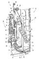
図1は、本発明の一実施形態に係る複合機10の外観斜視図である。図2は、複合機10のプリンタ部11の内部構造を示す縦断面図である。なお、図2においては、給紙トレイ20(本発明における第1トレイの一例)の一部及び排紙トレイ21(本発明における第2トレイの一例)が省略されている。
<Schematic configuration of MFP 10>
FIG. 1 is an external perspective view of a multifunction machine 10 according to an embodiment of the present invention. FIG. 2 is a longitudinal sectional view showing the internal structure of the printer unit 11 of the multifunction machine 10. In FIG. 2, a part of the paper feed tray 20 (an example of the first tray in the present invention) and a paper discharge tray 21 (an example of the second tray in the present invention) are omitted.

図1に示されるように、複合機10は、プリンタ部11及びスキャナ部12を備えた多機能装置(MFD:Multi Function Device)であり、プリント機能、スキャン機能、コピー機能、ファクシミリ機能を有する。本発明に係る画像記録装置は、複合機10のプリンタ部11として実施されている。したがって、プリント機能以外の機能は任意のものである。なお、本実施形態においては、プリンタ部11が画像記録にインクを使用するインクジェットプリンタである形態について説明される。ただし、プリンタ部11は、画像記録にトナーを使用するレーザプリンタであってもよい。   As shown in FIG. 1, the multifunction machine 10 is a multi-function device (MFD) having a printer unit 11 and a scanner unit 12, and has a print function, a scan function, a copy function, and a facsimile function. The image recording apparatus according to the present invention is implemented as the printer unit 11 of the multifunction machine 10. Therefore, functions other than the print function are arbitrary. In the present embodiment, a mode in which the printer unit 11 is an ink jet printer that uses ink for image recording will be described. However, the printer unit 11 may be a laser printer that uses toner for image recording.

複合機10は、主にコンピュータ等の外部情報装置(不図示)と接続される。複合機10は、外部情報装置から受信した印刷データに基づいて記録用紙(本発明におけるシートの一例)に画像を記録する。また、複合機10は、スキャナ部12によって読み取られた原稿の画像データに基づいて記録用紙に画像を記録する。また、複合機10は、デジタルカメラ等が接続されて、デジタルカメラ等から出力される画像データに基づいて記録用紙に画像を記録する。また、複合機10は、メモリカード等の各種記憶媒体が装填されて、該記憶媒体に記憶された画像データ等に基づいて記録用紙に画像を記録する。   The multifunction machine 10 is mainly connected to an external information device (not shown) such as a computer. The multifunction device 10 records an image on a recording sheet (an example of a sheet in the present invention) based on print data received from an external information device. The multifunction device 10 records an image on a recording sheet based on the image data of the original read by the scanner unit 12. The multifunction machine 10 is connected to a digital camera or the like, and records an image on a recording sheet based on image data output from the digital camera or the like. The multifunction machine 10 is loaded with various storage media such as a memory card, and records an image on a recording sheet based on image data stored in the storage medium.

図1に示されるように、複合機10は、高さより横幅及び奥行きが大きい幅広薄型の概ね直方体形状に形成されている。プリンタ部11は、その装置本体35の正面36側に開口13を有する。この開口13は、画像が記録されて開口13内に胴内排出された記録用紙をユーザが取り出すためのものである。この開口13内には、記録用紙を収容する給紙カセット70(図6参照)が配置される。給紙カセット70は、開口13を通じて装置本体35に対して挿抜される。なお、図1では給紙カセット70が省略されている。   As shown in FIG. 1, the multifunction machine 10 is formed in a wide and thin, generally rectangular parallelepiped shape having a width and depth larger than the height. The printer unit 11 has an opening 13 on the front side 36 of the apparatus main body 35. The opening 13 is for the user to take out the recording paper on which an image is recorded and discharged into the cylinder in the opening 13. A paper feed cassette 70 (see FIG. 6) for storing recording paper is disposed in the opening 13. The paper feed cassette 70 is inserted into and removed from the apparatus main body 35 through the opening 13. In FIG. 1, the paper feed cassette 70 is omitted.

装置本体35の正面36の右下部には、扉38(図1参照)が開閉自在に設けられている。扉38の内側にはカートリッジ装着部66が設けられている。図1に示されるように扉38が開かれると、カートリッジ装着部66が装置本体35の正面36側に露出される。これにより、カートリッジ装着部66に対するインクカートリッジ68の挿抜が可能になる。インクカートリッジ68は、カートリッジ装着部66に装着されることにより、インクチューブを介してインクジェット記録ヘッド41(図3参照)と連結される。インクジェット記録ヘッド41は、インクカートリッジ68から供給されるインクを吐出して記録用紙に画像を記録する。   A door 38 (see FIG. 1) is provided at the lower right portion of the front surface 36 of the apparatus main body 35 so as to be freely opened and closed. A cartridge mounting portion 66 is provided inside the door 38. As shown in FIG. 1, when the door 38 is opened, the cartridge mounting portion 66 is exposed to the front surface 36 side of the apparatus main body 35. Thereby, the ink cartridge 68 can be inserted into and removed from the cartridge mounting portion 66. The ink cartridge 68 is connected to the ink jet recording head 41 (see FIG. 3) via an ink tube by being mounted on the cartridge mounting portion 66. The ink jet recording head 41 discharges ink supplied from the ink cartridge 68 and records an image on a recording sheet.

複合機10の上部がスキャナ部12である。スキャナ部12は、フラットベッドスキャナ(FBS:Flat Bed Scanner)、及び自動原稿搬送装置(ADF:Automatic Document Feeder)を有して構成されている。図1に示されるように、複合機10の天板として原稿カバー30が開閉自在に設けられている。ADFは、この原稿カバー30に設けられている。図には示されていないが、原稿カバー30の下側には、プラテンガラス及びイメージセンサが設けられている。スキャナ部12では、プラテンガラスに載置された原稿、又はADFにより搬送される原稿の画像がイメージセンサによって読み取られる。   The upper part of the multifunction machine 10 is a scanner unit 12. The scanner unit 12 includes a flat bed scanner (FBS) and an automatic document feeder (ADF). As shown in FIG. 1, a document cover 30 is provided as a top plate of the multifunction machine 10 so as to be freely opened and closed. The ADF is provided on the document cover 30. Although not shown in the drawing, a platen glass and an image sensor are provided below the document cover 30. In the scanner unit 12, an image of a document placed on the platen glass or a document conveyed by the ADF is read by an image sensor.

複合機10の正面上部には、操作パネル14が設けられている。操作パネル14は、各種情報を表示する液晶ディスプレイ、ユーザが情報を入力する入力キー等から構成される。なお、図1では、液晶ディスプレイや入力キー等が省略されている。複合機10は、この操作パネル14からの操作入力、又は外部情報装置から送信される情報に基づいて動作する。   An operation panel 14 is provided in the upper front portion of the multifunction machine 10. The operation panel 14 includes a liquid crystal display for displaying various information, an input key for the user to input information, and the like. In FIG. 1, a liquid crystal display, input keys, and the like are omitted. The multi-function device 10 operates based on an operation input from the operation panel 14 or information transmitted from an external information device.

<プリンタ部11>
以下に、プリンタ部11の構成が詳細に説明される。
<Printer unit 11>
The configuration of the printer unit 11 will be described in detail below.

図1に示されるように、プリンタ部11の正面36の中央に開口13が設けられている。給紙カセット70(図6参照)は、この開口13を通じて装置本体35に対して挿抜可能に設けられる。すなわち、給紙カセット70は、装置本体35に対して搬送方向90へ挿し込み可能、且つ装置本体35から引出方向92へ引き出し可能である。給紙カセット70は、給紙トレイ20及び排紙トレイ21を有して構成されている(図6参照)。給紙トレイ20には、画像記録に使用される記録用紙が載置される。排紙トレイ21には、画像が記録された記録用紙が排出される。搬送方向90は、給紙トレイ20に載置された記録用紙が第1搬送路22(本発明における第1搬送路の一例)へ供給される方向である。引出方向92は、装置本体35から給紙トレイ20が引き出される方向である。   As shown in FIG. 1, an opening 13 is provided in the center of the front surface 36 of the printer unit 11. The paper feed cassette 70 (see FIG. 6) is provided to be able to be inserted into and removed from the apparatus main body 35 through the opening 13. That is, the paper feed cassette 70 can be inserted into the apparatus main body 35 in the transport direction 90 and can be pulled out from the apparatus main body 35 in the pull-out direction 92. The paper feed cassette 70 has a paper feed tray 20 and a paper discharge tray 21 (see FIG. 6). A recording sheet used for image recording is placed on the sheet feeding tray 20. A recording sheet on which an image is recorded is discharged to the discharge tray 21. The transport direction 90 is a direction in which the recording paper placed on the paper feed tray 20 is supplied to the first transport path 22 (an example of the first transport path in the present invention). The drawing direction 92 is a direction in which the paper feed tray 20 is drawn from the apparatus main body 35.

図2に示されるように、プリンタ部11は、給紙トレイ20、給紙ローラ25(本発明におけるローラの一例)、アーム26、及び動力伝達機構27を備えている。なお、図2においては、給紙トレイ20の一部、及び排紙トレイ21が省略されている。   As shown in FIG. 2, the printer unit 11 includes a paper feed tray 20, a paper feed roller 25 (an example of a roller in the present invention), an arm 26, and a power transmission mechanism 27. In FIG. 2, a part of the paper feed tray 20 and the paper discharge tray 21 are omitted.

図3は、プリンタ部11の主要部を示す拡大断面図である。   FIG. 3 is an enlarged cross-sectional view showing the main part of the printer unit 11.

<給紙ローラ25>
図2及び図3に示されるように、給紙トレイ20の上側に給紙ローラ25が配置されている。給紙ローラ25は、給紙トレイ20上の記録用紙を第1搬送路22へ供給するものである。給紙トレイ20の上方にはアーム26が設けられている。給紙ローラ25は、このアーム26の先端側に回転可能に設けられている。給紙ローラ25は、不図示のモータを駆動源として動力伝達機構27を介して駆動伝達されて回転する。動力伝達機構27は複数のギヤを有し、これらが直列に噛合されることにより構成されている。
<Feeding roller 25>
As shown in FIGS. 2 and 3, a paper feed roller 25 is disposed above the paper feed tray 20. The paper feed roller 25 supplies recording paper on the paper feed tray 20 to the first transport path 22. An arm 26 is provided above the paper feed tray 20. The paper feed roller 25 is rotatably provided on the tip side of the arm 26. The paper feed roller 25 is rotated by being transmitted through a power transmission mechanism 27 using a motor (not shown) as a drive source. The power transmission mechanism 27 has a plurality of gears and is configured by meshing them in series.

<アーム26>
アーム26は、基軸28に支持されている。アーム26は、その基端部が基軸28に支持されている。これにより、アーム26は、基軸28を中心として給紙トレイ20に対して接離する方向へ回動可能である。これにより、給紙ローラ25は、給紙トレイ20に対して接離する方向へ移動可能に構成されている。アーム26は、アーム26及び給紙ローラ25の重量又はバネ等に付勢されて下側へ回動付勢されている。
<Arm 26>
The arm 26 is supported by the base shaft 28. The base end portion of the arm 26 is supported by the base shaft 28. As a result, the arm 26 can rotate in a direction in which the arm 26 contacts and separates from the paper feed tray 20 around the base shaft 28. Accordingly, the paper feed roller 25 is configured to be movable in a direction in which it is in contact with or separated from the paper feed tray 20. The arm 26 is biased to rotate downward by being biased by the weight of the arm 26 and the paper feed roller 25 or a spring.

アーム26が下側へ回動付勢されることにより、給紙ローラ25が給紙トレイ20上の記録用紙に圧接される。この状態で給紙ローラ25が回転されると、給紙ローラ25のローラ面と記録用紙との間に発生する摩擦力により、給紙トレイ20における最上位置の記録用紙が傾斜板32へ向けて送り出される。記録用紙の先端が傾斜板32に当接すると、記録用紙の束のうちの最上位置の1枚が捌かれて上方へ案内される。このようにして、記録用紙は、給紙トレイ20から第1搬送路22へ1枚ずつ供給される。   As the arm 26 is urged to rotate downward, the paper feed roller 25 is pressed against the recording paper on the paper feed tray 20. When the paper feeding roller 25 is rotated in this state, the uppermost recording paper in the paper feeding tray 20 is directed toward the inclined plate 32 by the frictional force generated between the roller surface of the paper feeding roller 25 and the recording paper. Sent out. When the leading edge of the recording sheet comes into contact with the inclined plate 32, one of the uppermost positions of the bundle of recording sheets is rolled and guided upward. In this way, the recording paper is supplied one by one from the paper feed tray 20 to the first transport path 22.

なお、給紙ローラ25は、給紙トレイ20に対して接離する方向へ移動可能であれば、必ずしもアーム26に支持される必要はない。給紙ローラ25は、例えば給紙トレイ20に対して上下動可能なフレームに支持されていてもよい。   Note that the paper feed roller 25 does not necessarily need to be supported by the arm 26 as long as it can move in a direction in which the paper feed tray 20 moves toward and away from the paper feed tray 20. The paper feed roller 25 may be supported by a frame that can move up and down with respect to the paper feed tray 20, for example.

<第1搬送路22>
傾斜板32の上方には、第1搬送路22が設けられている。第1搬送路22は、傾斜板32から上方へ向かった後、正面36側(図2における右側)へ横向きU字形状に曲がっている。第1搬送路22は、複合機10の背面側(図2における左側)から正面36側へと延び、記録部24(本発明における記録部の一例)を経て排紙トレイ21(図6参照)へ通じている。つまり、排紙トレイ21は、第1搬送路22における記録用紙の搬送方向下流側に配置されている。給紙トレイ20から供給された記録用紙は、第1搬送路22に沿って搬送される。記録用紙は、第1搬送路22に沿って下方から上方へUターンするように案内されて記録部24に至り、記録部24によって画像が記録された後、排紙トレイ21に排出される。
<First transport path 22>
A first transport path 22 is provided above the inclined plate 32. The first conveyance path 22 is bent in a U-shaped sideways toward the front side 36 (the right side in FIG. 2) after going upward from the inclined plate 32. The first conveyance path 22 extends from the rear side (left side in FIG. 2) of the multifunction machine 10 to the front side 36, and passes through the recording unit 24 (an example of the recording unit in the present invention) to the discharge tray 21 (see FIG. 6). Leads to That is, the paper discharge tray 21 is disposed on the downstream side of the first conveyance path 22 in the conveyance direction of the recording paper. The recording paper supplied from the paper feed tray 20 is transported along the first transport path 22. The recording sheet is guided to make a U-turn from the lower side to the upper side along the first conveyance path 22 to reach the recording unit 24, and after the image is recorded by the recording unit 24, the recording sheet is discharged to the paper discharge tray 21.

第1搬送路22は、記録部24等が配設されている箇所以外では、外側ガイド面と内側ガイド面とによって区画形成されている。例えば、複合機10の背面側の第1搬送路22の湾曲部分は、外側ガイド部材18と内側ガイド部材19とが所定の間隔で対向配置されることにより構成されている。この場合、外側ガイド部材18が湾曲外側のガイド面を構成し、内側ガイド部材19が湾曲内側のガイド面を構成する。   The first conveyance path 22 is defined by an outer guide surface and an inner guide surface, except for a portion where the recording unit 24 and the like are disposed. For example, the curved portion of the first conveyance path 22 on the back side of the multifunction machine 10 is configured by arranging the outer guide member 18 and the inner guide member 19 to face each other at a predetermined interval. In this case, the outer guide member 18 constitutes a curved outer guide surface, and the inner guide member 19 constitutes a curved inner guide surface.

<記録部24>
図3に示されるように、記録部24は、第1搬送路22が複合機10の背面側から正面36側へ延びる途中に配置されている。記録部24は、第1搬送路22における記録用紙の搬送過程において記録用紙に画像を記録するものである。記録部24は、キャリッジ40、インクジェット記録ヘッド41、及びプラテン42を備えている。インクジェット記録ヘッド41は、キャリッジ40に搭載されている。キャリッジ40は、ガイドレール43,44に沿って記録用紙の幅方向(図3における紙面垂直方向)に往復移動される。図3には示されていないが、ガイドレール44には、モータを駆動源とするベルト駆動機構が設けられている。このようなベルト駆動機構は周知であるが、例えば、ガイドレール44の幅方向両端付近に駆動プーリ及び従動プーリがそれぞれ設けられ、この駆動プーリ及び従動プーリに無端環状の駆動ベルトが巻架されてなる。ベルト駆動機構の駆動ベルトにキャリッジ40が連結されることにより、モータの駆動がベルト駆動機構を介してキャリッジ40へ伝達され、キャリッジ40が往復移動する。
<Recording unit 24>
As shown in FIG. 3, the recording unit 24 is disposed in the middle of the first conveyance path 22 extending from the back side of the multifunction machine 10 to the front side 36. The recording unit 24 records an image on the recording paper during the recording paper transporting process in the first transport path 22. The recording unit 24 includes a carriage 40, an inkjet recording head 41, and a platen 42. The ink jet recording head 41 is mounted on the carriage 40. The carriage 40 is reciprocated along the guide rails 43 and 44 in the width direction of the recording paper (the direction perpendicular to the paper surface in FIG. 3). Although not shown in FIG. 3, the guide rail 44 is provided with a belt drive mechanism using a motor as a drive source. Such a belt drive mechanism is well known. For example, a drive pulley and a driven pulley are provided near both ends of the guide rail 44 in the width direction, and an endless annular drive belt is wound around the drive pulley and the driven pulley. Become. By connecting the carriage 40 to the drive belt of the belt drive mechanism, the drive of the motor is transmitted to the carriage 40 via the belt drive mechanism, and the carriage 40 reciprocates.

第1搬送路22には、インクジェット記録ヘッド41と対向するプラテン42が設けられている。プラテン42は、第1搬送路22を搬送される記録用紙を下から支持する。プラテン42により、記録用紙がインクジェット記録ヘッド41と所定のヘッドギャップを有して支持される。複合機10の内部には、インクジェット記録ヘッド41と独立してインクカートリッジ68が配置されている(図1参照)。インクカートリッジ68に収容された各色インクは、インクチューブを通じてインクジェット記録ヘッド41へ供給される。キャリッジ40が往復移動される間に、インクジェット記録ヘッド41から各色インクが微小なインク滴としてプラテン42へ向けて選択的に吐出される。プラテン42上を搬送される記録用紙は、その搬送過程において記録部24によって画像が記録される。   A platen 42 facing the ink jet recording head 41 is provided in the first transport path 22. The platen 42 supports the recording paper conveyed through the first conveyance path 22 from below. A recording sheet is supported by the platen 42 with a predetermined head gap from the inkjet recording head 41. An ink cartridge 68 is disposed inside the multifunction device 10 independently of the ink jet recording head 41 (see FIG. 1). Each color ink accommodated in the ink cartridge 68 is supplied to the inkjet recording head 41 through an ink tube. While the carriage 40 is reciprocated, each color ink is selectively ejected from the inkjet recording head 41 toward the platen 42 as fine ink droplets. An image is recorded on the recording sheet conveyed on the platen 42 by the recording unit 24 during the conveyance process.

<第2搬送路23>
図3に示されるように、第2搬送路23(本発明における第2搬送路の一例)は、第1搬送路22及び給紙トレイ20に連結されている。詳細には、第2搬送路23の一端側が、第1搬送路22における記録部24の下流側(下流側部位45)と接続されている。また、第2搬送路23の他端側が、給紙トレイ20における給紙ローラ25より上流側(図3における右側)と接続されている。給紙トレイ20は、給紙ローラ25よりも下流側(図3における左側)が、傾斜板32を介して第1搬送路22と接続されている。このため、第2搬送路23は、給紙トレイ20を介して、第1搬送路22における記録部24の上流側(上流側部位46)と接続されている。第2搬送路23は、一方の面(記録面64:図4及び図5参照)に画像が記録されてスイッチバック搬送される記録用紙65を給紙トレイ20上へ導くものである。すなわち、第1搬送路22を搬送された記録用紙65がスイッチバック搬送されるものである。
<Second transport path 23>
As shown in FIG. 3, the second transport path 23 (an example of the second transport path in the present invention) is connected to the first transport path 22 and the paper feed tray 20. Specifically, one end side of the second conveyance path 23 is connected to the downstream side (downstream part 45) of the recording unit 24 in the first conveyance path 22. Further, the other end side of the second transport path 23 is connected to the upstream side (the right side in FIG. 3) of the paper feed tray 20 from the paper feed roller 25. The paper feed tray 20 is connected to the first transport path 22 via an inclined plate 32 on the downstream side (left side in FIG. 3) from the paper feed roller 25. For this reason, the second transport path 23 is connected to the upstream side (upstream part 46) of the recording unit 24 in the first transport path 22 via the paper feed tray 20. The second transport path 23 guides the recording paper 65 on which one image (recording surface 64: see FIGS. 4 and 5) is recorded and transported in a switchback manner onto the paper feed tray 20. In other words, the recording paper 65 conveyed through the first conveyance path 22 is switched back and conveyed.

第2搬送路23は、所定の間隔で対向配置された一対の上側ガイド部材47と下側ガイド部材48とによって区画形成されている。上側ガイド部材47及び下側ガイド部材48は、第1搬送路22の下流側部位45から給紙ローラ25の上流側へ向かって、斜め下方へ延出されている。   The second transport path 23 is defined by a pair of an upper guide member 47 and a lower guide member 48 that face each other at a predetermined interval. The upper guide member 47 and the lower guide member 48 extend obliquely downward from the downstream portion 45 of the first transport path 22 toward the upstream side of the paper feed roller 25.

<搬送部15>
搬送部15は、第1搬送路22及び第2搬送路23に沿って記録用紙を搬送するものである。この搬送部15は、上述の給紙ローラ25、搬送ローラ50、排紙ローラ51、及び経路切換部72(本発明における経路切換部の一例)を有して構成されている。
<Conveyor 15>
The transport unit 15 transports the recording paper along the first transport path 22 and the second transport path 23. The transport unit 15 includes the above-described paper feed roller 25, transport roller 50, paper discharge roller 51, and path switching unit 72 (an example of a path switching unit in the present invention).

図2及び図3に示されるように、第1搬送路22における記録部24よりも上流側に、搬送ローラ50が設けられている。搬送ローラ50の下側には、搬送ローラ50に圧接するピンチローラ(不図示)が設けられている。搬送ローラ50は、第1搬送路22の幅方向(図3における紙面垂直方向)に渡って設けられている。ピンチローラは、第1搬送路22の幅方向に所定間隔で複数が設けられている。搬送ローラ50とピンチローラによって、第1搬送路22を搬送される記録用紙が挟持されてプラテン42上へ搬送される。   As shown in FIGS. 2 and 3, a conveyance roller 50 is provided on the upstream side of the recording unit 24 in the first conveyance path 22. A pinch roller (not shown) that is in pressure contact with the conveyance roller 50 is provided below the conveyance roller 50. The transport roller 50 is provided across the width direction of the first transport path 22 (the direction perpendicular to the paper surface in FIG. 3). A plurality of pinch rollers are provided at predetermined intervals in the width direction of the first conveyance path 22. The recording sheet conveyed through the first conveying path 22 is nipped and conveyed onto the platen 42 by the conveying roller 50 and the pinch roller.

第1搬送路22における記録部24よりも下流側に、排紙ローラ51及び拍車52が設けられている。拍車52は、排紙ローラ51の上側に設けられており、排紙ローラ51に圧接されている。排紙ローラ51は、第1搬送路22の幅方向に渡って設けられている。拍車52は、第1搬送路22の幅方向に所定間隔で複数が設けられている。画像が記録された記録用紙は、排紙ローラ51及び拍車52に挟持されて、第1搬送路22の下流側部位45へ搬送される。   A paper discharge roller 51 and a spur 52 are provided downstream of the recording unit 24 in the first conveyance path 22. The spur 52 is provided on the upper side of the paper discharge roller 51 and is in pressure contact with the paper discharge roller 51. The paper discharge roller 51 is provided across the width direction of the first transport path 22. A plurality of spurs 52 are provided at predetermined intervals in the width direction of the first conveyance path 22. The recording paper on which the image is recorded is sandwiched between the paper discharge roller 51 and the spur 52 and is transported to the downstream portion 45 of the first transport path 22.

搬送ローラ50及び排紙ローラ51は、不図示のモータを駆動源として駆動される。搬送ローラ50及び排紙ローラ51の駆動は同期されており、画像記録時において間欠駆動され、画像記録の前後においては連続駆動される。これによって、記録用紙は、記録部24へ到達するまでは第1搬送路22を所定の速度で搬送され、記録部24へ到達すると所定の改行幅で間欠して搬送される。記録用紙の搬送が間欠された間に、キャリッジ40が往復移動されて、インクジェット記録ヘッド41によって記録用紙の所定位置に画像が記録される。   The transport roller 50 and the paper discharge roller 51 are driven using a motor (not shown) as a drive source. The driving of the transport roller 50 and the paper discharge roller 51 is synchronized, and is intermittently driven during image recording, and continuously driven before and after image recording. As a result, the recording sheet is conveyed at a predetermined speed through the first conveyance path 22 until reaching the recording unit 24, and is intermittently conveyed at a predetermined line feed width when reaching the recording unit 24. While the recording paper is intermittently conveyed, the carriage 40 is reciprocated, and an image is recorded at a predetermined position on the recording paper by the ink jet recording head 41.

<経路切換部72>
図2及び図3に示されるように、第1搬送路22における下流側部位45には、経路切換部72が設けられている。経路切換部72は、第1搬送路22を搬送された記録用紙を排紙トレイ21又は第2搬送路23へ送るものである。この経路切換部72は、スイッチバックローラ53、拍車54、フレーム55、及び拍車56を有して構成されている。
<Route switching unit 72>
As shown in FIGS. 2 and 3, a path switching unit 72 is provided in the downstream portion 45 in the first transport path 22. The path switching unit 72 sends the recording paper conveyed through the first conveyance path 22 to the paper discharge tray 21 or the second conveyance path 23. The path switching unit 72 includes a switchback roller 53, a spur 54, a frame 55, and a spur 56.

図3に示されるように、第1搬送路22における下流側部位45の直下流側には、スイッチバックローラ53及び拍車54が設けられている。拍車54は、スイッチバックローラ53の上側に設けられており、スイッチバックローラ53に圧接されている。スイッチバックローラ53は、第1搬送路22の幅方向に渡って設けられている。拍車54は、第1搬送路22の幅方向に所定間隔で複数が配置されている。第1搬送路22を搬送された記録用紙は、スイッチバックローラ53及び拍車54によって排紙トレイ21へ排出される。また、第1搬送路22を搬送された記録用紙は、スイッチバックローラ53及び拍車54によって第2搬送路23をスイッチバック搬送される。   As shown in FIG. 3, a switchback roller 53 and a spur 54 are provided immediately downstream of the downstream portion 45 in the first transport path 22. The spur 54 is provided above the switchback roller 53 and is in pressure contact with the switchback roller 53. The switchback roller 53 is provided across the width direction of the first conveyance path 22. A plurality of spurs 54 are arranged at predetermined intervals in the width direction of the first conveyance path 22. The recording paper conveyed through the first conveyance path 22 is discharged to the paper discharge tray 21 by the switchback roller 53 and the spur 54. Further, the recording paper conveyed through the first conveyance path 22 is switched back and conveyed along the second conveyance path 23 by the switchback roller 53 and the spur 54.

スイッチバックローラ53は、不図示のモータを駆動源として駆動される。スイッチバックローラ53は正逆双方向へ回転可能である。スイッチバックローラ53の回転方向は、モータの正逆転により制御される。なお、モータからスイッチバックローラ53への駆動伝達過程において、ギヤ列の切換によって、一定方向のモータの回転をスイッチバックローラ53の双方向の回転として伝達するようにしてもよい。スイッチバックローラ53の「正転」及び「逆転」は相対的なものであるが、本実施形態では、記録用紙を排紙トレイ21側へ送る回転が「正転」と称され、記録用紙を第2搬送路23へ送る回転が「逆転」と称される。   The switchback roller 53 is driven using a motor (not shown) as a drive source. The switchback roller 53 can rotate in both forward and reverse directions. The rotation direction of the switchback roller 53 is controlled by forward / reverse rotation of the motor. In the drive transmission process from the motor to the switchback roller 53, the rotation of the motor in a certain direction may be transmitted as the bidirectional rotation of the switchback roller 53 by switching the gear train. Although “forward rotation” and “reverse rotation” of the switchback roller 53 are relative, in this embodiment, rotation for feeding the recording paper to the discharge tray 21 side is referred to as “forward rotation”. The rotation sent to the second conveyance path 23 is referred to as “reverse rotation”.

拍車54は、フレーム55に支持されて、スイッチバックローラ53に対して接離可能にスライドされる。図2及び図3には詳細に示されていないが、拍車54は、その回転軸がコイルバネによって弾性付勢されて、常にスイッチバックローラ53に圧接されている。したがって、スイッチバックローラ53が回転されると、それに従動して拍車54も回転する。コイルバネによって拍車54に付与される弾性付勢力が、スイッチバックローラ53及び拍車54による記録用紙のニップ力である。スイッチバックローラ53及び拍車54は、画像記録直後の記録用紙を挟持するので、これらによるニップ力は比較的弱く設定されている。したがって、スイッチバックローラ53及び拍車54に挟持された状態で記録用紙に外力が付与されると、記録用紙の剛性(腰)にニップ力が負けて、記録用紙は容易に姿勢変化される。つまり、記録用紙に外力が付与されると、記録用紙がスイッチバックローラ53及び拍車54に対して滑りうる。   The spur 54 is supported by the frame 55 and is slidable with respect to the switchback roller 53. Although not shown in detail in FIGS. 2 and 3, the spur 54 is always in pressure contact with the switchback roller 53 with its rotating shaft elastically biased by a coil spring. Therefore, when the switchback roller 53 is rotated, the spur 54 is also rotated following the rotation. The elastic biasing force applied to the spur 54 by the coil spring is the nip force of the recording paper by the switchback roller 53 and the spur 54. Since the switchback roller 53 and the spur 54 sandwich the recording sheet immediately after image recording, the nip force by these is set to be relatively weak. Therefore, when an external force is applied to the recording paper while being sandwiched between the switchback roller 53 and the spur 54, the nip force is lost to the rigidity (waist) of the recording paper, and the orientation of the recording paper is easily changed. That is, when an external force is applied to the recording paper, the recording paper can slide with respect to the switchback roller 53 and the spur 54.

図4は、経路切換部72の拡大断面図であり、フレーム55が水平姿勢に維持された状態を示す。図5は、経路切換部72の拡大断面図であり、フレーム55が回動姿勢に維持された状態を示す。   FIG. 4 is an enlarged cross-sectional view of the path switching unit 72 and shows a state in which the frame 55 is maintained in a horizontal posture. FIG. 5 is an enlarged cross-sectional view of the path switching unit 72 and shows a state in which the frame 55 is maintained in a rotating posture.

図4及び図5に示されるように、経路切換部72は、フレーム55及び拍車56を備える。フレーム55には、上述のスイッチバックローラ53が回転自在に支持されている。フレーム55は、スイッチバックローラ53から搬送方向上流側(図4及び図5における左側)へ延出されて下流側部位45へ至る。フレーム55の延出端に拍車56が回転自在に支持されて、拍車56が下流側部位45に配置されている。フレーム55は、第1搬送路22の幅方向(図4及び図5における紙面垂直方向)に延出されている。拍車56は、第1搬送路22の幅方向に所定間隔で複数が配置されている。   As shown in FIGS. 4 and 5, the path switching unit 72 includes a frame 55 and a spur 56. The switchback roller 53 described above is rotatably supported on the frame 55. The frame 55 extends from the switchback roller 53 to the upstream side in the conveyance direction (the left side in FIGS. 4 and 5) and reaches the downstream portion 45. A spur 56 is rotatably supported on the extended end of the frame 55, and the spur 56 is disposed in the downstream portion 45. The frame 55 extends in the width direction of the first conveyance path 22 (the direction perpendicular to the paper surface in FIGS. 4 and 5). A plurality of spurs 56 are arranged at predetermined intervals in the width direction of the first conveyance path 22.

フレーム55は、スイッチバックローラ53の回転軸を中心として、延出端側(図4及び図5における左側)が回転可能に構成されている。フレーム55には、モータの駆動力が伝達されて、所定の回転位置に姿勢変化される。この回転位置は、後述される水平姿勢及び回動姿勢である。フレーム55の基端側に支持された拍車54、及びフレーム55の延出端に支持された拍車56は、フレーム55とともスイッチバックローラ53の回転軸周りに回転される。   The frame 55 is configured to be rotatable on the extending end side (the left side in FIGS. 4 and 5) around the rotation axis of the switchback roller 53. The driving force of the motor is transmitted to the frame 55, and the posture is changed to a predetermined rotational position. This rotational position is a horizontal posture and a rotational posture described later. The spur 54 supported on the base end side of the frame 55 and the spur 56 supported on the extended end of the frame 55 are rotated around the rotation axis of the switchback roller 53 together with the frame 55.

図4に示されるように、水平姿勢に維持されたフレーム55は、スイッチバックローラ53から水平方向へ、その延出端を延ばす。水平姿勢において、スイッチバックローラ53と拍車54とのニップ位置を通過する拍車56の接線57は、搬送ローラ50及びピンチローラによるニップ位置と、排紙ローラ51及び拍車52によるニップ位置とを結ぶ直線と一致する。つまり、記録用紙65は、搬送ローラ50及びピンチローラ、並びに排紙ローラ51及び拍車52にそれぞれ挟持されて接線57に沿って搬送される。そして、接線57に沿って搬送される記録用紙65は、拍車56の最下部を通過して、スイッチバックローラ53及び拍車54に挟持される。つまり、水平姿勢のフレーム55によって、記録用紙65が排紙トレイ21側へ案内される。   As shown in FIG. 4, the frame 55 maintained in the horizontal posture extends from the switchback roller 53 in the horizontal direction. In a horizontal posture, a tangent line 57 of the spur 56 passing through the nip position between the switchback roller 53 and the spur 54 is a straight line connecting the nip position by the conveying roller 50 and the pinch roller and the nip position by the paper discharge roller 51 and the spur 52. Matches. That is, the recording sheet 65 is nipped by the conveying roller 50 and the pinch roller, the discharge roller 51 and the spur 52, and is conveyed along the tangent line 57. The recording sheet 65 conveyed along the tangent line 57 passes through the lowermost portion of the spur 56 and is sandwiched between the switchback roller 53 and the spur 54. That is, the recording paper 65 is guided to the paper discharge tray 21 side by the horizontal frame 55.

図5に示されるように、回動姿勢に維持されたフレーム55は、スイッチバックローラ53から斜め下方へ、その延出端を延ばす。フレーム55が水平姿勢から回動姿勢へ姿勢変化することにより、フレーム55とともに、拍車54,56がスイッチバックローラ53の回転軸周りに回転する。記録用紙65は、その後端62が拍車56によって接線59方向へ案内される。ここで、接線59は、スイッチバックローラ53と拍車54とのニップ位置を通過する拍車56の接線である。回動姿勢のフレーム55によって、記録用紙65が第2搬送路23を通過できる方向へ案内される。この記録用紙65は、スイッチバックローラ53及び拍車54によって第2搬送路23に沿ってスイッチバック搬送される。   As shown in FIG. 5, the frame 55 maintained in the rotating posture extends its extending end obliquely downward from the switchback roller 53. By changing the posture of the frame 55 from the horizontal posture to the turning posture, the spurs 54 and 56 are rotated around the rotation axis of the switchback roller 53 together with the frame 55. The rear end 62 of the recording paper 65 is guided in the direction of the tangent 59 by a spur 56. Here, the tangent line 59 is a tangent line of the spur 56 passing through the nip position between the switchback roller 53 and the spur 54. The recording paper 65 is guided in a direction in which the recording paper 65 can pass through the second conveyance path 23 by the frame 55 in the rotating posture. The recording paper 65 is switchback transported along the second transport path 23 by the switchback roller 53 and the spur 54.

図4及び図5に示されるように、スイッチバックローラ53及び拍車54より搬送方向下流側(図4及び図5における右側)に拍車60が設けられている。拍車60は、第1搬送路22の幅方向に所定間隔で複数が設けられている。拍車60は、その最下部が拍車54の最下部より上側となる位置に配置されている。したがって、図4に示されるように、水平姿勢のフレーム55によって接線57に沿って搬送される記録用紙65は、拍車60とは接触しない。   As shown in FIGS. 4 and 5, a spur 60 is provided downstream of the switchback roller 53 and the spur 54 in the transport direction (the right side in FIGS. 4 and 5). A plurality of spurs 60 are provided at predetermined intervals in the width direction of the first conveyance path 22. The spur 60 is disposed at a position where the lowermost portion is above the lowermost portion of the spur 54. Accordingly, as shown in FIG. 4, the recording paper 65 conveyed along the tangent line 57 by the horizontal frame 55 does not contact the spur 60.

記録用紙65は、フレーム55が回動姿勢に維持された状態でスイッチバックローラ53によって接線59に沿ってスイッチバック搬送される。この記録用紙65は、その剛性によって、スイッチバックローラ53及び拍車54による挟持位置より排紙トレイ21側(図4及び図5における右側)の部分を、接線59に沿って上側へ持ち上げようとする。この場合に、図5に示されるように、記録用紙65の当該部分に拍車60が接触する。記録用紙65は、拍車60と接触することにより撓んで、スイッチバックローラ53に巻き付けられる。これにより、記録用紙65の剛性がスイッチバックローラ53への圧接力として作用する。   The recording paper 65 is conveyed in a switchback manner along the tangent line 59 by the switchback roller 53 with the frame 55 maintained in a rotating posture. Due to its rigidity, the recording paper 65 tends to lift the portion on the paper discharge tray 21 side (the right side in FIGS. 4 and 5) from the holding position by the switchback roller 53 and the spur 54 upward along the tangent line 59. . In this case, as shown in FIG. 5, the spur 60 contacts the portion of the recording paper 65. The recording sheet 65 is bent by contacting the spur 60 and wound around the switchback roller 53. As a result, the rigidity of the recording paper 65 acts as a pressing force against the switchback roller 53.

<給紙カセット70>
図6は、給紙カセット70の斜視図である。図7は、給紙トレイ20の構成を示す斜視図である。
<Paper cassette 70>
FIG. 6 is a perspective view of the paper feed cassette 70. FIG. 7 is a perspective view showing the configuration of the paper feed tray 20.

図6に示されるように、給紙カセット70は、全体として薄肉の直方体形状に形成されており、給紙トレイ20及び排紙トレイ21を備える。給紙トレイ20及び排紙トレイ21は、排紙トレイ21を給紙トレイ20の上側として上下二段となるように配置されている。給紙カセット70は、開口13を通じて装置本体35に対して挿抜される。給紙トレイ20及び排紙トレイ21は、給紙カセット70として一体的に構成されている。このため、装置本体35に対する給紙トレイ20の挿抜に併せて排紙トレイ21も挿抜される。   As shown in FIG. 6, the paper feed cassette 70 is formed in a thin rectangular parallelepiped shape as a whole, and includes a paper feed tray 20 and a paper discharge tray 21. The paper feed tray 20 and the paper discharge tray 21 are arranged in two upper and lower stages with the paper discharge tray 21 as the upper side of the paper feed tray 20. The paper feed cassette 70 is inserted into and removed from the apparatus main body 35 through the opening 13. The paper feed tray 20 and the paper discharge tray 21 are integrally configured as a paper feed cassette 70. For this reason, the paper discharge tray 21 is also inserted and removed together with the insertion and removal of the paper feed tray 20 from the apparatus main body 35.

給紙カセット70が装置本体35に装着される。これにより、アーム26及び給紙ローラ25の下方に給紙トレイ20が配置される(図6参照)。アーム26の基軸28は、その軸方向が第1方向94(本発明における第1方向に相当する)となるように装置本体35内のフレーム(不図示)に回動可能に設けられている。ここで、第1方向94は、給紙トレイ20に載置された記録用紙の搬送方向90と略直交する水平な方向である。基軸28は、不図示のモータを駆動源として軸方向周りに回転される。基軸28の回転が動力伝達機構27を介して給紙ローラ25へ伝達され、給紙ローラ25が回転駆動される。基軸28には、径方向及び軸方向に延びる多数のリブが設けられている。これにより、基軸28は、高いねじり剛性及び曲げ剛性が確保されている。図7に示されるように、給紙トレイ20には、幅方向(第1方向94)の中央に後述の摩擦部材104が設けられている。給紙カセット70は、給紙トレイ20に記録用紙が載置されていない状態で装置本体35に装着される。この場合、アーム26が給紙トレイ20側へ回動し、給紙ローラ25が摩擦部材104に当接される。   A paper feed cassette 70 is attached to the apparatus main body 35. As a result, the paper feed tray 20 is disposed below the arm 26 and the paper feed roller 25 (see FIG. 6). The base shaft 28 of the arm 26 is rotatably provided on a frame (not shown) in the apparatus main body 35 so that the axial direction thereof is the first direction 94 (corresponding to the first direction in the present invention). Here, the first direction 94 is a horizontal direction substantially perpendicular to the conveyance direction 90 of the recording paper placed on the paper feed tray 20. The base shaft 28 is rotated around the axial direction using a motor (not shown) as a drive source. The rotation of the base shaft 28 is transmitted to the paper feed roller 25 through the power transmission mechanism 27, and the paper feed roller 25 is rotationally driven. The base shaft 28 is provided with a large number of ribs extending in the radial direction and the axial direction. As a result, the base shaft 28 has high torsional rigidity and bending rigidity. As shown in FIG. 7, the paper feed tray 20 is provided with a friction member 104 described later at the center in the width direction (first direction 94). The paper feed cassette 70 is attached to the apparatus main body 35 with no recording paper placed on the paper feed tray 20. In this case, the arm 26 rotates toward the paper feed tray 20 and the paper feed roller 25 is brought into contact with the friction member 104.

<排紙トレイ21>
排紙トレイ21は、給紙カセット70の幅方向(第1方向94)を軸方向として、給紙トレイ20に対して上側へ回動可能に構成されている。給紙トレイ20に対して排紙トレイ21が起立されることにより、給紙トレイ20の上面が開放される。すなわち、給紙トレイ20への記録用紙の補充が可能となる。給紙トレイ20に対して排紙トレイ21が倒伏されることにより、給紙トレイ20の上面が排紙トレイ21に覆われる。後述されるが、給紙トレイ20には、トレイ本体102に対して搬送方向90及び引出方向92へスライド可能な拡張トレイ114(図7参照)が設けられている。給紙トレイ20に対して排紙トレイ21が倒伏されると、排紙トレイ21の後端部75が拡張トレイ114の後端部78に下方から支持され、排紙トレイ21の側壁106が給紙トレイ20の側壁123に下方から支持される。この状態で、排紙トレイ21は、画像が記録された記録用紙を保持するとともに給紙トレイ20の蓋として機能する。これにより、給紙トレイ20への紙粉やゴミの進入が防止される。なお、図6に示されるように、給紙トレイ20の奥側における上方は、給紙ローラ25やアーム26が配置されるために開放されている。
<Discharge tray 21>
The paper discharge tray 21 is configured to be rotatable upward with respect to the paper feed tray 20 with the width direction (first direction 94) of the paper feed cassette 70 as an axial direction. By raising the paper discharge tray 21 with respect to the paper feed tray 20, the upper surface of the paper feed tray 20 is opened. In other words, the recording paper can be replenished to the paper feed tray 20. When the paper discharge tray 21 is laid down with respect to the paper feed tray 20, the upper surface of the paper feed tray 20 is covered with the paper discharge tray 21. As will be described later, the paper feed tray 20 is provided with an extension tray 114 (see FIG. 7) that can slide in the transport direction 90 and the pull-out direction 92 with respect to the tray body 102. When the paper discharge tray 21 is laid down with respect to the paper feed tray 20, the rear end portion 75 of the paper discharge tray 21 is supported from below by the rear end portion 78 of the expansion tray 114, and the side wall 106 of the paper discharge tray 21 is fed. It is supported on the side wall 123 of the paper tray 20 from below. In this state, the paper discharge tray 21 holds a recording sheet on which an image is recorded and functions as a lid of the paper feed tray 20. This prevents paper dust and dust from entering the paper feed tray 20. As shown in FIG. 6, the upper side on the back side of the paper feed tray 20 is open because the paper feed roller 25 and the arm 26 are arranged.

<給紙トレイ20>
図7に示されるように、給紙トレイ20は、平面視で搬送方向90及び引出方向92に長い矩形の皿状に概ね形成されている。給紙トレイ20は、トレイ本体102及び拡張トレイ114を有する。給紙トレイ20は、トレイ本体102に対して拡張トレイ114が搬送方向90及び引出方向92へスライド可能に構成されている。図7には、トレイ本体102に対して拡張トレイ114が搬送方向90へ押し込まれた状態が示されている。ここで、搬送方向90は、給紙トレイ20上の記録用紙が第1搬送路22へ供給される方向である。この搬送方向90は、給紙トレイ20が装置本体35の開口13(図1参照)内へ押し込まれる方向と略同じ方向である。引出方向92は、給紙トレイ20が装置本体35から引き出される方向である。
<Paper Tray 20>
As shown in FIG. 7, the paper feed tray 20 is generally formed in a rectangular dish shape that is long in the transport direction 90 and the pull-out direction 92 in plan view. The paper feed tray 20 includes a tray main body 102 and an expansion tray 114. The sheet feeding tray 20 is configured such that the expansion tray 114 can slide in the transport direction 90 and the drawing direction 92 with respect to the tray body 102. FIG. 7 shows a state where the extension tray 114 is pushed in the transport direction 90 with respect to the tray main body 102. Here, the transport direction 90 is a direction in which the recording paper on the paper feed tray 20 is supplied to the first transport path 22. The transport direction 90 is substantially the same as the direction in which the paper feed tray 20 is pushed into the opening 13 (see FIG. 1) of the apparatus main body 35. The drawing direction 92 is a direction in which the paper feed tray 20 is drawn from the apparatus main body 35.

拡張トレイ114は、必要に応じてトレイ本体102に対して搬送方向90又は引出方向92へスライドされる。これにより、給紙トレイ20のシート積載面が拡張又は縮小され、給紙トレイ20に各種サイズの記録用紙を収容することができる。本実施形態においては、日本工業規格に規定される各種サイズの記録用紙が給紙トレイ20に載置される。各種サイズとしては、A4サイズ、B5サイズ、A5サイズ、はがきサイズ、写真L判サイズ等が挙げられる。したがって、本実施形態においては、給紙トレイ20に載置可能な記録用紙の最大サイズがA4サイズであり、給紙トレイ20に載置可能な記録用紙の最小サイズが写真L判サイズである。ただし、給紙トレイ20に載置可能な記録用紙の最大サイズ及び最小サイズはこれに限定されるものではない。給紙トレイ20は、例えば、写真L判サイズからA3サイズまでの各種サイズの記録用紙を載置可能なものであってもよい。   The expansion tray 114 is slid in the transport direction 90 or the pull-out direction 92 with respect to the tray body 102 as necessary. Thereby, the sheet stacking surface of the paper feed tray 20 is expanded or reduced, and recording papers of various sizes can be stored in the paper feed tray 20. In the present embodiment, recording papers of various sizes specified by Japanese Industrial Standards are placed on the paper feed tray 20. Examples of the various sizes include A4 size, B5 size, A5 size, postcard size, and photograph L size. Therefore, in this embodiment, the maximum size of the recording paper that can be placed on the paper feed tray 20 is A4 size, and the minimum size of the recording paper that can be placed on the paper feed tray 20 is the photo L size. However, the maximum size and the minimum size of the recording paper that can be placed on the paper feed tray 20 are not limited to this. For example, the paper feed tray 20 may be capable of placing recording paper of various sizes from a photo L size to an A3 size.

図7に示されるように、トレイ本体102は、搬送方向90及び引出方向92に長い矩形状に形成されている。トレイ本体102は、底板84を有する。記録用紙は、この底板84に載置される。上述の傾斜板32は、トレイ本体102の先端74に設けられている。傾斜板32は、トレイ本体102の幅方向(第1方向94)に長い板状部材である。傾斜板32は、装置背面側(搬送方向90側)へ傾倒している。したがって、傾斜板32に記録用紙の先端が当接すると、その先端が傾斜板32の内側面77に沿って斜め上方へ案内される。すなわち、内側面77は、記録用紙を第1搬送路22(図3参照)へ案内するガイド面の役割を担う。   As shown in FIG. 7, the tray body 102 is formed in a rectangular shape that is long in the transport direction 90 and the pull-out direction 92. The tray body 102 has a bottom plate 84. The recording sheet is placed on the bottom plate 84. The inclined plate 32 described above is provided at the tip 74 of the tray body 102. The inclined plate 32 is a plate-like member that is long in the width direction of the tray body 102 (first direction 94). The inclined plate 32 is tilted toward the back side of the apparatus (the conveyance direction 90 side). Therefore, when the leading edge of the recording sheet comes into contact with the inclined plate 32, the leading edge is guided obliquely upward along the inner surface 77 of the inclined plate 32. That is, the inner side surface 77 serves as a guide surface for guiding the recording paper to the first transport path 22 (see FIG. 3).

図7に示されるように、第1方向94におけるトレイ本体102の中央に、摩擦部材104が設けられている。2つの給紙ローラ25(図6参照)は、アーム26が回動されることにより給紙トレイ20側へ移動される。これにより、給紙ローラ25は、摩擦部材104の直上に配置される。摩擦部材104は、記録用紙との摩擦係数が高い例えばコルクやゴム等からなる。記録用紙が載置された給紙トレイ20が装置本体35に装着されると、給紙ローラ25が給紙トレイ20上の記録用紙に圧接される。これにより、記録用紙は、摩擦部材104及び給紙ローラ25に挟み込まれる。摩擦部材104及び給紙ローラ25に挟まれた複数の記録用紙のうち、上位層の記録用紙には、搬送方向90への摩擦力が給紙ローラ25から付与される。これに対し、下位層の記録用紙には、摩擦部材104から引出方向92への摩擦力が給紙ローラ25から付与される。なお、本実施形態においては、アーム26に2つの給紙ローラ25が支持されている形態について説明されるが、給紙ローラ25は1つであってもよい。   As shown in FIG. 7, a friction member 104 is provided at the center of the tray body 102 in the first direction 94. The two paper feed rollers 25 (see FIG. 6) are moved to the paper feed tray 20 side when the arm 26 is rotated. As a result, the paper feed roller 25 is disposed immediately above the friction member 104. The friction member 104 is made of, for example, cork or rubber having a high friction coefficient with the recording paper. When the paper feed tray 20 on which the recording paper is placed is mounted on the apparatus main body 35, the paper feed roller 25 is pressed against the recording paper on the paper feed tray 20. As a result, the recording paper is sandwiched between the friction member 104 and the paper feed roller 25. Of the plurality of recording sheets sandwiched between the friction member 104 and the sheet feeding roller 25, a frictional force in the transport direction 90 is applied from the sheet feeding roller 25 to the upper layer recording sheet. On the other hand, a frictional force in the pulling direction 92 from the friction member 104 is applied from the paper feed roller 25 to the lower layer recording paper. In the present embodiment, the form in which the two paper feed rollers 25 are supported by the arm 26 will be described. However, the number of the paper feed rollers 25 may be one.

底板84には、底板84の幅方向(第1方向94)に沿って一対のガイド溝86,87が設けられている(図7参照)。ガイド溝86,87は、第1方向94に長い長方形のものであって、底板64を表面から裏面へ貫通した形状に形成されている。給紙トレイ20を搬送方向90の上流側から見て左側にガイド溝86が設けられており、右側にガイド溝87が設けられている。ガイド溝86及びガイド溝87は、第1方向94に隔てられている。   The bottom plate 84 is provided with a pair of guide grooves 86 and 87 along the width direction (first direction 94) of the bottom plate 84 (see FIG. 7). The guide grooves 86 and 87 have a rectangular shape that is long in the first direction 94 and are formed in a shape that penetrates the bottom plate 64 from the front surface to the back surface. A guide groove 86 is provided on the left side when the sheet feeding tray 20 is viewed from the upstream side in the conveyance direction 90, and a guide groove 87 is provided on the right side. The guide groove 86 and the guide groove 87 are separated in the first direction 94.

図7に示されるように、底板84の幅方向中央位置にピニオンギヤ82が設けられている。ピニオンギヤ82は、ガイド溝86及びガイド溝87の中間位置に設けられている。ピニオンギヤ82は、底板84の裏面において後述のラックギヤ88,89が噛合される。   As shown in FIG. 7, a pinion gear 82 is provided at the center position in the width direction of the bottom plate 84. The pinion gear 82 is provided at an intermediate position between the guide groove 86 and the guide groove 87. The pinion gear 82 meshes with rack gears 88 and 89 described later on the back surface of the bottom plate 84.

<サイドガイド80,81>
トレイ本体102には、図7に示されるように、一対のサイドガイド80,81が設けられている。サイドガイド80は、トレイ本体102を搬送方向90の上流側から見て左側に配置されている。サイドガイド81(本発明における位置決め部材の一例、本発明におけるサイドガイドに相当する)は、トレイ本体102を搬送方向90の上流側から見て右側に配置されている。サイドガイド80,81は、例えばABS樹脂などの合成樹脂からなる。サイドガイド80,81は、第1方向94における縦断面が略L字形状に形成されたものである。サイドガイド80,81は、給紙トレイ20内を移動可能に構成されている。具体的には、サイドガイド80,81は、トレイ本体102の幅方向(第1方向94)へスライド可能に設けられている。サイドガイド80は、ガイド溝86に沿ってスライド可能に底板84に支持されている。サイドガイド81は、ガイド溝87に沿ってスライド可能に底板84に支持されている。
<Side guides 80 and 81>
As shown in FIG. 7, the tray main body 102 is provided with a pair of side guides 80 and 81. The side guide 80 is disposed on the left side when the tray body 102 is viewed from the upstream side in the transport direction 90. The side guide 81 (an example of a positioning member in the present invention, which corresponds to the side guide in the present invention) is disposed on the right side when the tray body 102 is viewed from the upstream side in the transport direction 90. The side guides 80 and 81 are made of synthetic resin such as ABS resin. The side guides 80 and 81 are formed in a substantially L-shaped longitudinal section in the first direction 94. The side guides 80 and 81 are configured to be movable in the paper feed tray 20. Specifically, the side guides 80 and 81 are provided to be slidable in the width direction (first direction 94) of the tray main body 102. The side guide 80 is supported by the bottom plate 84 so as to be slidable along the guide groove 86. The side guide 81 is supported by the bottom plate 84 so as to be slidable along the guide groove 87.

サイドガイド80,81は、給紙トレイ20に対して記録用紙を位置決めするものである。サイドガイド80,81は、給紙トレイ20に載置された記録用紙の第1方向94における端部に当接される。これにより、給紙トレイ20に載置された記録用紙の幅方向の位置がサイドガイド80,81によって規制される。サイドガイド80,81は、給紙トレイ20に載置された記録用紙の幅方向(第1方向94)における中央位置を給紙トレイ20の基準位置(本実施形態では給紙トレイ20の幅方向の中央)に略一致させる。このように、記録用紙の幅方向の中央位置を基準位置に一致させるように記録用紙を規制することは、一般にセンターレジと呼ばれる。給紙トレイ20に載置された記録用紙は、サイドガイド80,81によって搬送方向90へ案内され、第1搬送路22へ供給される。   The side guides 80 and 81 are for positioning the recording paper with respect to the paper feed tray 20. The side guides 80 and 81 are in contact with the end portions in the first direction 94 of the recording paper placed on the paper feed tray 20. As a result, the position in the width direction of the recording paper placed on the paper feed tray 20 is regulated by the side guides 80 and 81. The side guides 80 and 81 have a central position in the width direction (first direction 94) of the recording paper placed on the paper feed tray 20 as a reference position of the paper feed tray 20 (in this embodiment, the width direction of the paper feed tray 20). Approximately in the middle). In this manner, restricting the recording sheet so that the center position in the width direction of the recording sheet coincides with the reference position is generally called a center register. The recording paper placed on the paper feed tray 20 is guided in the transport direction 90 by the side guides 80 and 81 and supplied to the first transport path 22.

トレイ本体102には、トレイ本体102の幅方向の両端に側壁122,123が設けられている。側壁122,123は、トレイ本体102の底板84から上方へ垂直に起立している。図7には、サイドガイド80の垂直壁128が側壁122に当接され、サイドガイド81の垂直壁118が側壁123に当接された状態が示されている。この状態において、給紙トレイ20には、A4サイズの記録用紙が載置される。サイドガイド80は、垂直壁128が側壁122から離間する第1方向94へスライドされる。サイドガイド81は、垂直壁118が側壁123から離間する第1方向94へスライドされる。これにより、給紙トレイ20に例えば写真L判サイズの記録用紙が載置された場合に、その記録用紙は、第1方向94におけるトレイ本体102の略中央に位置決めされる。   The tray body 102 is provided with side walls 122 and 123 at both ends in the width direction of the tray body 102. The side walls 122 and 123 stand vertically upward from the bottom plate 84 of the tray main body 102. FIG. 7 shows a state where the vertical wall 128 of the side guide 80 is in contact with the side wall 122 and the vertical wall 118 of the side guide 81 is in contact with the side wall 123. In this state, A4 size recording paper is placed on the paper feed tray 20. The side guide 80 is slid in a first direction 94 in which the vertical wall 128 is separated from the side wall 122. The side guide 81 is slid in a first direction 94 in which the vertical wall 118 is separated from the side wall 123. As a result, when a recording sheet of, for example, a photographic L size is placed on the sheet feeding tray 20, the recording sheet is positioned approximately at the center of the tray body 102 in the first direction 94.

図7に示されるように、サイドガイド81は、底壁117及び垂直壁118を備えている。底壁117は、トレイ本体102の底板84に平行に配置されるものである。記録用紙は、その幅方向の一端がこの底壁117に載置される。垂直壁118は、底壁117の幅方向外側の端縁から垂直に立設されている。図には表れていないが、記録用紙は、底壁117に載置された状態で、その幅方向の一端が垂直壁118の内側面に当接される。このように、サイドガイド81には、第1方向94における記録用紙の端部が当接される。   As shown in FIG. 7, the side guide 81 includes a bottom wall 117 and a vertical wall 118. The bottom wall 117 is disposed in parallel to the bottom plate 84 of the tray main body 102. One end of the recording sheet in the width direction is placed on the bottom wall 117. The vertical wall 118 is erected vertically from the outer edge in the width direction of the bottom wall 117. Although not shown in the drawing, the recording sheet is placed on the bottom wall 117, and one end in the width direction is brought into contact with the inner surface of the vertical wall 118. As described above, the end portion of the recording sheet in the first direction 94 is brought into contact with the side guide 81.

垂直壁118には、レバー99が設けられている。レバー99は、サイドガイド81と一体に形成されており、同じ樹脂で構成されている。底板84の表面に、複数のスリット95が形成されている。各スリット95は、その長手方向が搬送方向90に一致するように形成されている。これらのスリット95は、第1方向へ並べられている。本実施形態では、図7に示されるように、複数のスリット95からなる2本のスリット群が形成されている。図には表れていないが、レバー99は、上記2本のスリット群に対応する位置に2つの爪が設けられている。これらの爪が2本のスリット群のいずれかのスリット95に挿入されることで、底板84に対してサイドガイド81が固定される。ユーザがレバー99を操作することにより、爪が持ち上げられる。これにより、爪がスリット95から抜き出されてサイドガイド81の固定が解除され、サイドガイド81がスライド可能となる。   A lever 99 is provided on the vertical wall 118. The lever 99 is formed integrally with the side guide 81 and is made of the same resin. A plurality of slits 95 are formed on the surface of the bottom plate 84. Each slit 95 is formed such that its longitudinal direction coincides with the transport direction 90. These slits 95 are arranged in the first direction. In the present embodiment, as shown in FIG. 7, two slit groups each including a plurality of slits 95 are formed. Although not shown in the figure, the lever 99 is provided with two claws at positions corresponding to the two slit groups. The side guide 81 is fixed to the bottom plate 84 by inserting these claws into one of the slits 95 of the two slit groups. When the user operates the lever 99, the nail is lifted. As a result, the claw is extracted from the slit 95, the fixation of the side guide 81 is released, and the side guide 81 can be slid.

サイドガイド81には、底壁117から幅方向中央側へ延出されたラックギヤ89が設けられている。ラックギヤ89は、ガイド溝87を介して底板84の裏面側に配置され、上述のピニオンギヤ82に噛合されている。   The side guide 81 is provided with a rack gear 89 extending from the bottom wall 117 to the center in the width direction. The rack gear 89 is disposed on the back surface side of the bottom plate 84 through the guide groove 87 and is meshed with the pinion gear 82 described above.

サイドガイド80は、レバー99及び後述のプレート136(本発明におけるプレートの一例)を有しない点を除いて、サイドガイド81と略対称な形状に形成されている。サイドガイド80は、サイドガイド81と同様に、底壁127及び垂直壁128を有する。記録用紙は、その幅方向の他端がこの底壁127に載置される。垂直壁128は、底壁127の幅方向外側の端縁から垂直に立設されている。図には表れていないが、記録用紙は、底壁127に載置された状態で、その幅方向の他端が垂直壁128の内側面に当接される。   The side guide 80 is formed in a substantially symmetric shape with the side guide 81 except that the side guide 80 does not have a lever 99 and a plate 136 (an example of a plate in the present invention) described later. Similar to the side guide 81, the side guide 80 has a bottom wall 127 and a vertical wall 128. The other end of the recording sheet in the width direction is placed on the bottom wall 127. The vertical wall 128 is erected vertically from the outer edge of the bottom wall 127 in the width direction. Although not shown in the drawing, the recording sheet is placed on the bottom wall 127, and the other end in the width direction is brought into contact with the inner surface of the vertical wall 128.

サイドガイド80には、ラックギヤ89と略同様に構成されたラックギヤ88が設けられている。ラックギヤ88は、ガイド溝86を介して底板84の裏面側に配置され、上述のピニオンギヤ82に噛合されている。   The side guide 80 is provided with a rack gear 88 configured substantially the same as the rack gear 89. The rack gear 88 is disposed on the back surface side of the bottom plate 84 via the guide groove 86 and meshes with the pinion gear 82 described above.

サイドガイド80,81のうちいずれか一方が第1方向94へスライドされる。これに連動して、サイドガイド80,81のうちの他方が相反する方向へスライドされる。したがって、給紙トレイ20に載置された記録用紙の幅がサイドガイド80,81の離間距離よりも短い場合は、サイドガイド80,81の一方をスライドさせることにより、サイドガイド80,81が同時に移動される。これにより、記録用紙の幅方向の中央位置が上記基準位置に略一致する。   One of the side guides 80 and 81 is slid in the first direction 94. In conjunction with this, the other of the side guides 80 and 81 is slid in the opposite direction. Accordingly, when the width of the recording paper placed on the paper feed tray 20 is shorter than the separation distance between the side guides 80 and 81, the side guides 80 and 81 are simultaneously moved by sliding one of the side guides 80 and 81. Moved. As a result, the central position in the width direction of the recording paper substantially matches the reference position.

なお、サイドガイド80,81は、その一方のみがスライド可能に構成されていてもよい。例えば、図9に示される位置に固定されたサイドガイド80に対してサイドガイド81がスライドされる、所謂サイドレジが採用されてもよい。記録用紙の第1方向94における中央が略一致される給紙トレイ20の基準位置が記録用紙のサイズに応じて変化する。   Note that only one of the side guides 80 and 81 may be slidable. For example, a so-called side register in which the side guide 81 is slid with respect to the side guide 80 fixed at the position shown in FIG. 9 may be employed. The reference position of the paper feed tray 20 at which the center of the recording paper in the first direction 94 is substantially matched changes according to the size of the recording paper.

<リヤガイド120>
トレイ本体102における第1方向94の中央に、リヤガイド120が設けられている。リヤガイド120は、給紙トレイ20に対して記録用紙を位置決めするものである。リヤガイド120は、給紙トレイ20に載置された記録用紙の搬送方向90における上流側の端部に当接される。このため、給紙トレイ20に載置された記録用紙は、給紙トレイ20に対して引出方向92へ移動することがリヤガイド120によって規制される。
<Rear guide 120>
A rear guide 120 is provided in the center of the tray body 102 in the first direction 94. The rear guide 120 is for positioning the recording paper with respect to the paper feed tray 20. The rear guide 120 is brought into contact with an upstream end portion in the transport direction 90 of the recording paper placed on the paper feed tray 20. Therefore, the rear guide 120 restricts the recording paper placed on the paper feed tray 20 from moving in the drawing direction 92 with respect to the paper feed tray 20.

リヤガイド120は、給紙トレイ20内を移動可能に構成されている。具体的には、リヤガイド120は、給紙トレイ20に対して搬送方向90及び引出方向92へスライド可能に構成されている。底板84には、搬送方向90及び引出方向92に長い溝97が形成されている。この溝97は、トレイ本体102の長手方向の略中央付近から後端まで延設されている。リヤガイド120は、この溝97に沿ってスライド可能にトレイ本体102に設けられている。   The rear guide 120 is configured to be movable in the paper feed tray 20. Specifically, the rear guide 120 is configured to be slidable in the transport direction 90 and the drawing direction 92 with respect to the paper feed tray 20. The bottom plate 84 is formed with a long groove 97 in the transport direction 90 and the drawing direction 92. The groove 97 extends from the vicinity of the center of the tray body 102 in the longitudinal direction to the rear end. The rear guide 120 is provided on the tray main body 102 so as to be slidable along the groove 97.

第1方向94における溝97の両側には、複数のスリット85が形成されている。各スリット85は、その長手方向が溝97に直交する方向に一致する。図には示されていないが、リヤガイド120には、溝97を挟んだ両側のスリット85に挿抜される2つの爪が設けられている。また、リヤガイド120には、リヤガイド120と一体に形成されたレバー79が設けられている。レバー79は、リヤガイド120と一体に形成されており、同じ樹脂で構成されている。リヤガイド120の爪がいずれかのスリット85に挿入されることで、底板84に対してリヤガイド120が固定される。ユーザがレバー79を操作することにより、リヤガイド120の爪が持ち上げられる。これにより、爪がスリット85から抜き出されてリヤガイド120の固定が解除され、リヤガイド120がスライド可能となる。   A plurality of slits 85 are formed on both sides of the groove 97 in the first direction 94. Each slit 85 coincides with the direction in which the longitudinal direction is orthogonal to the groove 97. Although not shown in the drawing, the rear guide 120 is provided with two claws that are inserted into and removed from the slits 85 on both sides of the groove 97. The rear guide 120 is provided with a lever 79 formed integrally with the rear guide 120. The lever 79 is formed integrally with the rear guide 120 and is made of the same resin. The rear guide 120 is fixed to the bottom plate 84 by inserting the claws of the rear guide 120 into any of the slits 85. When the user operates the lever 79, the claw of the rear guide 120 is lifted. As a result, the pawl is extracted from the slit 85, the rear guide 120 is released, and the rear guide 120 can be slid.

給紙トレイ20に記録用紙が載置された状態で、リヤガイド120が溝97に沿って搬送方向90へスライドされる。これにより、リヤガイド120が記録用紙の後端に当接する。その結果、記録用紙の搬送方向90における上流側の端部が揃えられるとともに、当該端部が記録用紙のサイズに応じた位置に規制される。記録用紙は、その搬送方向90における下流側の端部が、記録用紙のサイズに拘わらず給紙トレイ20内の傾斜板32に近接する所定位置に略一致される。   With the recording paper placed on the paper feed tray 20, the rear guide 120 is slid along the groove 97 in the transport direction 90. As a result, the rear guide 120 contacts the trailing edge of the recording paper. As a result, the upstream end in the recording sheet conveyance direction 90 is aligned, and the end is restricted to a position corresponding to the size of the recording sheet. The downstream end of the recording sheet in the transport direction 90 is substantially coincident with a predetermined position close to the inclined plate 32 in the sheet feeding tray 20 regardless of the size of the recording sheet.

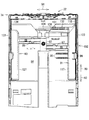
図8は、図7におけるVIII部の拡大図である。図9は、トレイ本体102の平面図であり、サイドガイド80,81が給紙トレイ20に載置される最大サイズの記録用紙を保持する第1位置に配置された状態を示す。図10は、サイドガイド81が第1方向94におけるトレイ本体102の中央へスライドされる様子を示す模式図である。なお、図9においては、トレイ本体102における引出方向92側の一部とリヤガイド120が省略されている。   FIG. 8 is an enlarged view of a portion VIII in FIG. FIG. 9 is a plan view of the tray main body 102 and shows a state in which the side guides 80 and 81 are arranged at the first position for holding the maximum size recording paper placed on the paper feed tray 20. FIG. 10 is a schematic diagram illustrating a state in which the side guide 81 is slid to the center of the tray main body 102 in the first direction 94. In FIG. 9, a part of the tray body 102 on the side of the drawing direction 92 and the rear guide 120 are omitted.

<プレート136>
図7〜図9に示されるように、サイドガイド81は、第1方向94におけるトレイ本体102の中央へ向けて底壁117からプレート136(本発明におけるプレートの一例)が延出されている。プレート136は、第1方向94を長手方向とする平板部材であり、底壁117と平行に設けられている。プレート136は、搬送方向90において摩擦部材104と略同じ位置に設けられている(図7及び図9参照)。給紙トレイ20に載置された記録用紙は、その側壁123側の端部が底壁117及びプレート136に載置される。すなわち、プレート136は、給紙トレイ20に載置された記録用紙の下面の一部に当接される。記録用紙は、側壁123側の端部が底壁117及びプレート136に下方から支持される。
<Plate 136>
As shown in FIGS. 7 to 9, in the side guide 81, a plate 136 (an example of a plate in the present invention) extends from the bottom wall 117 toward the center of the tray body 102 in the first direction 94. The plate 136 is a flat plate member having the first direction 94 as a longitudinal direction, and is provided in parallel with the bottom wall 117. The plate 136 is provided at substantially the same position as the friction member 104 in the transport direction 90 (see FIGS. 7 and 9). The recording paper placed on the paper feed tray 20 is placed on the bottom wall 117 and the plate 136 at the end on the side wall 123 side. That is, the plate 136 is brought into contact with a part of the lower surface of the recording paper placed on the paper feed tray 20. The end of the recording paper on the side wall 123 side is supported by the bottom wall 117 and the plate 136 from below.

<凹部141,142>
図8に示されるように、プレート136の上面側には、凹部141,142(本発明における凹部の一例)が形成されている。凹部141,142は、プレート136における記録用紙との当接面138(図8及び図9参照)から下方へ凹むようにプレート136に形成されている(図10参照)。後述のクリーニング部材131,132(本発明におけるクリーニング部材の一例)は、凹部141,142にそれぞれ収容される。
<Recesses 141, 142>
As shown in FIG. 8, recesses 141 and 142 (an example of a recess in the present invention) are formed on the upper surface side of the plate 136. The concave portions 141 and 142 are formed in the plate 136 so as to be recessed downward from the contact surface 138 (see FIGS. 8 and 9) of the plate 136 with the recording paper (see FIG. 10). Cleaning members 131 and 132 (an example of the cleaning member in the present invention) described later are accommodated in the recesses 141 and 142, respectively.

後述されるが、第1方向94におけるトレイ本体102の中央へサイドガイド81がスライドされることにより、クリーニング部材131又はクリーニング部材132が2つの給紙ローラ25の直下に配置される(図10(C)及び(D)参照)。凹部141は、2つの給紙ローラ25のローラ面の一部が凹部141内へ進入して、クリーニング部材131に圧接可能な大きさに形成されている。また、凹部142は、2つの給紙ローラ25のローラ面の一部が凹部142内へ進入して、クリーニング部材132に圧接可能な大きさに形成されている。具体的には、図10(A)に示されるように、第1方向94における凹部141,142の幅L1が2つの給紙ローラ25の軸方向長さH1よりも幅広に設定されている。また、図には示されていないが、搬送方向90における凹部141,142の幅が、少なくとも給紙ローラ25のローラ面の一部が凹部141又は凹部142内へ進入可能な広さに設定されている。   As will be described later, when the side guide 81 is slid toward the center of the tray main body 102 in the first direction 94, the cleaning member 131 or the cleaning member 132 is disposed directly below the two paper feed rollers 25 (FIG. 10 ( C) and (D)). The recess 141 is formed in such a size that a part of the roller surfaces of the two paper feed rollers 25 can enter the recess 141 and can be pressed against the cleaning member 131. The concave portion 142 is formed in a size that allows a part of the roller surfaces of the two paper feed rollers 25 to enter the concave portion 142 and press-contact with the cleaning member 132. Specifically, as shown in FIG. 10A, the width L1 of the recesses 141 and 142 in the first direction 94 is set wider than the axial length H1 of the two paper feed rollers 25. Although not shown in the drawing, the widths of the concave portions 141 and 142 in the transport direction 90 are set to a width that allows at least a part of the roller surface of the paper feeding roller 25 to enter the concave portion 141 or the concave portion 142. ing.

<クリーニング部材131,132>
図7〜図9に示されるように、サイドガイド81には2つのクリーニング部材131,132が設けられている。本実施形態においては、クリーニング部材131,132は、凹部141,142にそれぞれ収容されている(図10(A)参照)。クリーニング部材131,132は、2つの給紙ローラ25をクリーニングするものである。ここで、クリーニングとは、給紙ローラ25にクリーニング部材131又はクリーニング部材132を接触させた状態で給紙ローラ25を回転駆動させる動作である。これにより、給紙ローラ25に付着した紙粉、インク、ゴミ等がクリーニング部材131又はクリーニング部材132によって給紙ローラ25から除去される。なお、プリンタ部11がインクジェットプリンタではなくレーザプリンタである場合には、給紙ローラ25に付着したトナーを除去する動作も本発明のクリーニングに含まれる。この除去動作に使用されるクリーニング部材131,132としては、弾性変形が可能なものが好適に用いられる。クリーニング部材131,132としては、ゴム、ブラシ、フェルト等が挙げられるが、給紙ローラ25のローラ面の材質を考慮して適宜変更され得る。
<Cleaning members 131 and 132>
As shown in FIGS. 7 to 9, the side guide 81 is provided with two cleaning members 131 and 132. In the present embodiment, the cleaning members 131 and 132 are accommodated in the recesses 141 and 142, respectively (see FIG. 10A). The cleaning members 131 and 132 are for cleaning the two paper feed rollers 25. Here, the cleaning is an operation of rotating the paper feed roller 25 while the cleaning member 131 or the cleaning member 132 is in contact with the paper feed roller 25. As a result, paper dust, ink, dust or the like attached to the paper feed roller 25 is removed from the paper feed roller 25 by the cleaning member 131 or the cleaning member 132. When the printer unit 11 is a laser printer instead of an ink jet printer, the operation of removing the toner attached to the paper feed roller 25 is also included in the cleaning of the present invention. As the cleaning members 131 and 132 used for this removal operation, those capable of elastic deformation are preferably used. Examples of the cleaning members 131 and 132 include rubber, brush, felt, and the like. However, the cleaning members 131 and 132 may be appropriately changed in consideration of the material of the roller surface of the paper feed roller 25.

クリーニング部材131,132は、凹部141,142内に収容可能な大きさに構成されている。このため、クリーニング部材131は、当接面138よりも上方へ露出しないように凹部141に収容される。また、クリーニング部材132は、当接面138よりも上方へ露出しないように凹部142に収容される。このため、記録用紙が給紙トレイ20に載置された場合に、すなわち、記録用紙が当接面138に当接された場合に、記録用紙とクリーニング部材131,132とが互いに接触することがない。これにより、クリーニング部材131,132が給紙ローラ25から除去した紙粉、インク、ゴミ等が記録用紙に付着するすることが防止されている。   The cleaning members 131 and 132 are configured to have a size that can be accommodated in the recesses 141 and 142. For this reason, the cleaning member 131 is accommodated in the recess 141 so as not to be exposed above the contact surface 138. Further, the cleaning member 132 is accommodated in the recess 142 so as not to be exposed above the contact surface 138. For this reason, when the recording paper is placed on the paper feed tray 20, that is, when the recording paper comes into contact with the contact surface 138, the recording paper and the cleaning members 131 and 132 may come into contact with each other. Absent. This prevents paper dust, ink, dust, etc. removed by the cleaning members 131 and 132 from the paper feed roller 25 from adhering to the recording paper.

次に、サイドガイド81のスライドに伴う給紙ローラ25とクリーニング部材131,132との位置関係について説明される。   Next, the positional relationship between the paper feed roller 25 and the cleaning members 131 and 132 that accompany the slide of the side guide 81 will be described.

図11は、トレイ本体102の平面図であり、サイドガイド80,81が給紙トレイ20に載置される最小サイズの記録用紙を保持する第1位置に配置された状態を示す。図12は、トレイ本体102の平面図であり、給紙ローラ25がクリーニング部材131に圧接される第2位置に配置された状態を示す。図13は、トレイ本体102の平面図であり、給紙ローラ25がクリーニング部材132に圧接される第2位置に配置された状態を示す。なお、図11〜図13においては、トレイ本体102における引出方向92側の一部とリヤガイド120が省略されている。   FIG. 11 is a plan view of the tray main body 102 and shows a state in which the side guides 80 and 81 are arranged at the first position for holding the minimum size recording paper placed on the paper feed tray 20. FIG. 12 is a plan view of the tray main body 102 and shows a state in which the paper feed roller 25 is disposed at the second position where it is pressed against the cleaning member 131. FIG. 13 is a plan view of the tray main body 102 and shows a state in which the paper feed roller 25 is disposed at the second position where it is pressed against the cleaning member 132. 11 to 13, a part of the tray main body 102 on the side of the drawing direction 92 and the rear guide 120 are omitted.

サイドガイド80,81は、給紙トレイ20内を第1方向94へスライド可能に構成されている。サイドガイド81には、上述のようにプレート136にクリーニング部材131,132が設けられている。サイドガイド81は、第1方向94へスライドされることにより、第1位置と第2位置との間を移動される。第1位置(図9及び図11参照)は、給紙トレイ20に載置される記録用紙をそのサイズに応じた基準位置にサイドガイド81がサイドガイド80とともに保持する位置である。本実施形態における第1位置は、サイドガイド80,81が、給紙トレイ20に載置される記録用紙の幅方向の中央を第1方向94におけるトレイ本体102の略中央に位置決めする位置である。なお、第1位置は、給紙トレイ20に載置される記録用紙の各サイズに対応して複数の位置をとりうる。第2位置(図12及び図13参照)は、給紙トレイ20に記録用紙が載置されていない状態で給紙トレイ20側へ移動された給紙ローラ25がクリーニング部材131又はクリーニング部材132に圧接される位置である。本実施形態においては、サイドガイド81に2つのクリーニング部材131,132が設けられているので、第2位置は、2つの位置をとりうる。   The side guides 80 and 81 are configured to be slidable in the first direction 94 within the paper feed tray 20. The side guide 81 is provided with the cleaning members 131 and 132 on the plate 136 as described above. The side guide 81 is moved between the first position and the second position by sliding in the first direction 94. The first position (see FIGS. 9 and 11) is a position where the side guide 81 holds the recording paper placed on the paper feed tray 20 together with the side guide 80 at a reference position according to the size. The first position in the present embodiment is a position where the side guides 80 and 81 position the center in the width direction of the recording paper placed on the paper feed tray 20 to the approximate center of the tray main body 102 in the first direction 94. . The first position can take a plurality of positions corresponding to each size of the recording paper placed on the paper feed tray 20. In the second position (see FIGS. 12 and 13), the paper feed roller 25 moved to the paper feed tray 20 side with no recording paper placed on the paper feed tray 20 is placed on the cleaning member 131 or the cleaning member 132. It is a position to be pressed. In the present embodiment, since the two cleaning members 131 and 132 are provided on the side guide 81, the second position can take two positions.

<第1位置>
給紙トレイ20に載置可能な最大サイズ(本実施形態においてはA4サイズ)の記録用紙を画像記録に使用する使用する場合、サイドガイド80,81は、ユーザにより第1方向94におけるトレイ本体102の外側へ向けてスライドされる。サイドガイド80,81は、垂直壁128が側壁122に当接するとともに垂直壁118が側壁123に当接する位置(図9参照)までスライドされる。これにより、垂直壁128と垂直壁118との離間距離がAサイズの記録用紙の幅と略等しくなり、サイドガイド81は、給紙トレイ20に載置されるA4サイズの記録用紙を保持する第1位置に配置される(図9及び図10(A)参照)。給紙トレイ20に載置されたA4サイズの記録用紙は、その幅方向の両端にサイドガイド80,81の垂直壁128,118が当接される。また、図9には示されていないが、リヤガイド120(図7参照)が搬送方向90における下流側へスライドされることにより、A4サイズの記録用紙の後端にリヤガイド120が当接される。これにより、A4サイズの記録用紙は、給紙トレイ20に対してA4サイズに応じた所定の基準位置に位置決めされる。給紙トレイ20は、このようにA4サイズの記録用紙が載置された状態で装置本体35に装着される。
<First position>
When the recording paper of the maximum size (A4 size in the present embodiment) that can be placed on the paper feed tray 20 is used for image recording, the side guides 80 and 81 are used for the tray main body 102 in the first direction 94 by the user. Slide towards the outside. The side guides 80 and 81 are slid to a position (see FIG. 9) where the vertical wall 128 contacts the side wall 122 and the vertical wall 118 contacts the side wall 123. As a result, the distance between the vertical wall 128 and the vertical wall 118 becomes substantially equal to the width of the A-size recording paper, and the side guide 81 holds the A4-size recording paper placed on the paper feed tray 20. It arrange | positions at 1 position (refer FIG.9 and FIG.10 (A)). The A4 size recording paper placed on the paper feed tray 20 is brought into contact with the vertical walls 128 and 118 of the side guides 80 and 81 at both ends in the width direction. Although not shown in FIG. 9, the rear guide 120 (see FIG. 7) is slid downstream in the transport direction 90, so that the rear guide 120 comes into contact with the rear end of the A4 size recording sheet. As a result, the A4 size recording paper is positioned at a predetermined reference position corresponding to the A4 size with respect to the paper feed tray 20. The paper feed tray 20 is attached to the apparatus main body 35 with the A4 size recording paper placed thereon in this way.

給紙トレイ20に載置可能な最小サイズ(本実施形態においては写真L判サイズ)の記録用紙を画像記録に使用する場合、サイドガイド80,81は、ユーザにより第1方向94におけるトレイ本体102の中央へ所定の位置までスライドされる(図9及び図11参照)。これにより、垂直壁128と垂直壁118との離間距離が写真L判サイズの記録用紙の幅と略等しくなり、サイドガイド81は、給紙トレイ20に載置される写真L判サイズの記録用紙を保持する第1位置に配置される(図11及び図10(B)参照)。給紙トレイ20に載置された写真L判サイズの記録用紙は、その幅方向の両端にサイドガイド80,81の垂直壁128,118が当接される。また、図11には示されていないが、リヤガイド120(図7参照)が搬送方向90における下流側へスライドされることにより、写真L判サイズの記録用紙の後端にリヤガイド120が当接される。これにより、写真L判サイズの記録用紙は、給紙トレイ20に対して写真L判サイズに応じた所定の基準位置に位置決めされる。給紙トレイ20は、このように写真L判サイズの記録用紙が載置された状態で装置本体35に装着される。   When recording paper of a minimum size (photo L size in this embodiment) that can be placed on the paper feed tray 20 is used for image recording, the side guides 80 and 81 are used by the user for the tray main body 102 in the first direction 94. Is slid to a predetermined position (see FIGS. 9 and 11). As a result, the separation distance between the vertical wall 128 and the vertical wall 118 is substantially equal to the width of the photographic L-size recording paper, and the side guide 81 is placed on the paper feed tray 20 for the photographic L-size recording paper. (See FIGS. 11 and 10B). The photographic L size recording paper placed on the paper feed tray 20 is brought into contact with the vertical walls 128 and 118 of the side guides 80 and 81 at both ends in the width direction. Although not shown in FIG. 11, the rear guide 120 (see FIG. 7) is slid downstream in the transport direction 90, so that the rear guide 120 is brought into contact with the rear end of the photographic L size recording paper. The As a result, the photographic L size recording paper is positioned at a predetermined reference position corresponding to the photographic L size with respect to the paper feed tray 20. The paper feed tray 20 is attached to the apparatus main body 35 in such a state that the photo L size recording paper is thus placed.

なお、本実施形態における第1位置は、サイドガイド81が給紙トレイ20に載置されたA4サイズ又は写真L判サイズの記録用紙を保持する位置に限定されるものではない。すなわち、ここでの第1位置は、サイドガイド81が給紙トレイ20に載置された他のサイズ(例えば、はがきサイズ)の記録用紙を保持する位置であってもよい。   Note that the first position in the present embodiment is not limited to the position where the side guide 81 holds the recording paper of A4 size or photographic L size placed on the paper feed tray 20. That is, the first position here may be a position where the side guide 81 holds a recording sheet of another size (for example, a postcard size) placed on the sheet feeding tray 20.

<第2位置>
サイドガイド80,81は、給紙トレイ20に記録用紙が載置されていない状態において、ユーザにより第1方向94におけるトレイ本体102の中央へ向けてスライドされる。図12及び図10(C)に示されるように、サイドガイド80,81は、クリーニング部材131がトレイ本体102の幅方向の中央(摩擦部材104の直上)に配置される位置に配置される。給紙トレイ20は、この状態で記録用紙が載置されることなく装置本体35に装着される。給紙トレイ20に記録用紙が載置されていないので、アーム26(図6参照)が給紙トレイ20側へ回動される。これにより、給紙ローラ25がクリーニング部材131に圧接された状態となる(図10(C)参照)。このように、クリーニング部材131が摩擦部材104の直上に配置される位置までサイドガイド81がスライドされた後、給紙トレイ20が装置本体35に装着される。その結果、サイドガイド81は、給紙ローラ25がクリーニング部材131に圧接される第2位置に配置される。本実施形態においては、クリーニング部材131がゴムで形成されているので、給紙ローラ25にクリーニング部材131が密着する。
<Second position>
The side guides 80 and 81 are slid toward the center of the tray main body 102 in the first direction 94 by the user in a state where no recording paper is placed on the paper feed tray 20. As shown in FIGS. 12 and 10C, the side guides 80 and 81 are disposed at positions where the cleaning member 131 is disposed at the center in the width direction of the tray body 102 (directly above the friction member 104). In this state, the paper feed tray 20 is mounted on the apparatus main body 35 without placing the recording paper. Since no recording paper is placed on the paper feed tray 20, the arm 26 (see FIG. 6) is rotated to the paper feed tray 20 side. As a result, the paper feed roller 25 is in pressure contact with the cleaning member 131 (see FIG. 10C). As described above, after the side guide 81 is slid to the position where the cleaning member 131 is disposed immediately above the friction member 104, the paper feed tray 20 is mounted on the apparatus main body 35. As a result, the side guide 81 is disposed at the second position where the paper feed roller 25 is pressed against the cleaning member 131. In the present embodiment, since the cleaning member 131 is made of rubber, the cleaning member 131 is in close contact with the paper feed roller 25.

サイドガイド80,81は、給紙トレイ20に記録用紙が載置されていない状態において、ユーザにより第1方向94におけるトレイ本体102の中央へ向けてスライドされる。図13及び図10(D)に示されるように、サイドガイド80,81は、クリーニング部材132がトレイ本体102の幅方向の中央(摩擦部材104の直上)に配置される位置に配置される。給紙トレイ20は、この状態で記録用紙が載置されることなく装置本体35に装着される。給紙トレイ20に記録用紙が載置されていないので、アーム26(図6参照)が給紙トレイ20側へ回動される。これにより、給紙ローラ25がクリーニング部材132に圧接された状態となる(図10(C)参照)。このように、クリーニング部材132が摩擦部材104の直上に配置される位置までサイドガイド81をスライドされた後、給紙トレイ20が装置本体35に装着される。その結果、サイドガイド81は、給紙ローラ25がクリーニング部材132に圧接される第2位置に配置される。本実施形態においては、クリーニング部材132がゴムで形成されているので、給紙ローラ25にクリーニング部材132が密着する。   The side guides 80 and 81 are slid toward the center of the tray main body 102 in the first direction 94 by the user in a state where no recording paper is placed on the paper feed tray 20. As shown in FIGS. 13 and 10D, the side guides 80 and 81 are disposed at positions where the cleaning member 132 is disposed at the center in the width direction of the tray main body 102 (directly above the friction member 104). In this state, the paper feed tray 20 is mounted on the apparatus main body 35 without placing the recording paper. Since no recording paper is placed on the paper feed tray 20, the arm 26 (see FIG. 6) is rotated to the paper feed tray 20 side. As a result, the paper feed roller 25 is brought into pressure contact with the cleaning member 132 (see FIG. 10C). As described above, after the side guide 81 is slid to the position where the cleaning member 132 is disposed immediately above the friction member 104, the paper feed tray 20 is mounted on the apparatus main body 35. As a result, the side guide 81 is disposed at the second position where the paper feed roller 25 is pressed against the cleaning member 132. In the present embodiment, since the cleaning member 132 is formed of rubber, the cleaning member 132 is in close contact with the paper feed roller 25.

<画像記録>
給紙トレイ20は、サイドガイド81が第1位置に配置された状態で記録用紙が載置される。これにより、記録用紙は、給紙トレイ20に対してその記録用紙のサイズに応じた基準位置に位置決めされる。この給紙トレイ20は、開口13(図1参照)を通じて装置本体35に装着される。給紙トレイ20に記録用紙が載置されているので、給紙ローラ25が給紙トレイ20上の記録用紙に圧接される。操作パネル14からのユーザの所定操作に基づいて印刷開始が指示されると、給紙ローラ25が回転駆動される。これにより、給紙トレイ20上の記録用紙が矢印17(図3参照)の方向に第1搬送路22へ供給される。給紙トレイ20から第1搬送路22へ供給された記録用紙65は、搬送ローラ50とピンチローラ、及び排紙ローラ51と拍車52によって第1搬送路22に沿って搬送される。この記録用紙65は、その搬送過程で記録部24によって一方の面(記録面64)に画像が記録される。
<Image recording>
On the paper feed tray 20, the recording paper is placed with the side guide 81 placed at the first position. As a result, the recording sheet is positioned with respect to the paper feed tray 20 at a reference position corresponding to the size of the recording sheet. The paper feed tray 20 is attached to the apparatus main body 35 through the opening 13 (see FIG. 1). Since the recording paper is placed on the paper feed tray 20, the paper feed roller 25 is pressed against the recording paper on the paper feed tray 20. When the start of printing is instructed based on a predetermined user operation from the operation panel 14, the paper feed roller 25 is driven to rotate. As a result, the recording paper on the paper feed tray 20 is supplied to the first transport path 22 in the direction of the arrow 17 (see FIG. 3). The recording paper 65 supplied from the paper feed tray 20 to the first conveyance path 22 is conveyed along the first conveyance path 22 by a conveyance roller 50 and a pinch roller, and a paper discharge roller 51 and a spur 52. An image is recorded on one surface (recording surface 64) of the recording paper 65 by the recording unit 24 during the conveyance process.

印刷設定が片面記録に設定されている場合、経路切換部72のフレーム55が水平姿勢に維持された状態(図4参照)でスイッチバックローラ53が正転される。これにより、記録面64に画像が記録された記録用紙65は、第1搬送路22から排紙トレイ21へ排出される。   When the print setting is set to single-sided recording, the switchback roller 53 is normally rotated while the frame 55 of the path switching unit 72 is maintained in the horizontal posture (see FIG. 4). As a result, the recording paper 65 having an image recorded on the recording surface 64 is discharged from the first transport path 22 to the paper discharge tray 21.

印刷設定が両面記録に設定されている場合、フレーム55が水平姿勢に維持された状態でスイッチバックローラ53が正転される。これにより、上述のように記録面64に画像が記録された記録用紙65は、排紙トレイ21側(図4における右側)へ送られる。そして、この記録用紙65の後端62が拍車56よりも上流側の規定位置に到達したとき(図4に示される状態)に、フレーム55が水平姿勢から回動姿勢へ姿勢変化される(図4及び図5参照)。記録用紙65の後端62は、拍車56によって下側へ押圧され、第2搬送路23側へ向けられる(図5参照)。   When the print setting is set to double-sided recording, the switchback roller 53 is normally rotated while the frame 55 is maintained in the horizontal posture. Thereby, the recording paper 65 on which the image is recorded on the recording surface 64 as described above is sent to the discharge tray 21 side (the right side in FIG. 4). Then, when the rear end 62 of the recording sheet 65 reaches the specified position upstream of the spur 56 (the state shown in FIG. 4), the frame 55 is changed in posture from the horizontal posture to the rotating posture (see FIG. 4 and FIG. 5). The rear end 62 of the recording sheet 65 is pressed downward by the spur 56 and directed toward the second transport path 23 (see FIG. 5).

スイッチバックローラ53が逆転されることにより、記録用紙65は搬送方向が変えられて、第2搬送路23に沿ってスイッチバック搬送される。この記録用紙65は、第2搬送路23から給紙トレイ20へ送られる。具体的には、記録用紙65は、給紙トレイ20に載置された最上位置の記録用紙と給紙ローラ25との間(以下、「当接位置」とも称される。)へ送られる。記録用紙65の後端62が当接位置に到達すると、給紙ローラ25が回転駆動されて記録用紙65が記録部24の上流側(上流側部位46)へ送られる。これにより、記録用紙65は表裏反転される。すなわち、記録用紙65がプラテン42上へ搬送された際に記録面64とは反対側の面がインクジェット記録ヘッド41と対向する。記録用紙65は、プラテン42上を通過する際に他方の面(記録面64の反対側の面)に画像が記録される。記録用紙65が第2搬送路23から第1搬送路22へ送られると、経路切換部72のアーム55が回動姿勢から水平姿勢へ姿勢変化される。両面に画像が記録された記録用紙65は、スイッチバックローラ53が正転されることにより第1搬送路22から排紙トレイ21へ排出される。   By reversing the switchback roller 53, the recording sheet 65 is changed in the conveyance direction and is switched back and conveyed along the second conveyance path 23. The recording paper 65 is sent from the second transport path 23 to the paper feed tray 20. Specifically, the recording sheet 65 is sent between the uppermost recording sheet placed on the sheet feeding tray 20 and the sheet feeding roller 25 (hereinafter also referred to as “contact position”). When the rear end 62 of the recording paper 65 reaches the contact position, the paper feed roller 25 is driven to rotate, and the recording paper 65 is sent to the upstream side (upstream portion 46) of the recording unit 24. As a result, the recording paper 65 is reversed. That is, when the recording paper 65 is conveyed onto the platen 42, the surface opposite to the recording surface 64 faces the ink jet recording head 41. When the recording paper 65 passes over the platen 42, an image is recorded on the other surface (the surface opposite to the recording surface 64). When the recording paper 65 is sent from the second conveyance path 23 to the first conveyance path 22, the arm 55 of the path switching unit 72 is changed in posture from the rotation posture to the horizontal posture. The recording paper 65 on which images are recorded on both sides is discharged from the first conveyance path 22 to the paper discharge tray 21 by the normal rotation of the switchback roller 53.

プリンタ部11では、給紙トレイ20から第1搬送路22へ記録用紙を供給するために、給紙トレイ20上の記録用紙に給紙ローラ25が圧接された状態で回転駆動される。このため、給紙ローラ25には、記録用紙上の紙粉やゴミが付着する。また、プリンタ部11において両面記録が行われる場合、記録面64(図4及び図5参照)に画像が記録された記録用紙65は、第1搬送路22へ再送される際に記録面64に給紙ローラ25が圧接される。記録面64は、上述のように、記録部24によってインクが付着された記録用紙65の一方の面である。インクが充分に乾燥していない状態で記録用紙65が第1搬送路22へ再送されると、記録用紙65上のインクが給紙ローラ25に付着することがある。このように、給紙ローラ25には、紙粉、ゴミ、インク等が付着する。その結果、給紙トレイ20から第1搬送路22への記録用紙の供給不良が生じる場合がある。   In the printer unit 11, in order to supply the recording paper from the paper feed tray 20 to the first conveyance path 22, the printer unit 11 is rotationally driven in a state where the paper feed roller 25 is pressed against the recording paper on the paper feed tray 20. For this reason, paper dust and dust on the recording paper adhere to the paper feed roller 25. Further, when double-sided recording is performed in the printer unit 11, the recording paper 65 on which an image is recorded on the recording surface 64 (see FIGS. 4 and 5) is transferred to the recording surface 64 when being retransmitted to the first conveyance path 22. The paper feed roller 25 is pressed. As described above, the recording surface 64 is one surface of the recording paper 65 to which ink is adhered by the recording unit 24. If the recording paper 65 is retransmitted to the first transport path 22 in a state where the ink is not sufficiently dried, the ink on the recording paper 65 may adhere to the paper feed roller 25. In this way, paper dust, dust, ink, and the like adhere to the paper feed roller 25. As a result, a recording paper supply failure from the paper feed tray 20 to the first transport path 22 may occur.

本実施形態における複合機10では、サイドガイド81を第1方向94におけるトレイ本体102の中央へスライドさせた後に給紙トレイ20を装置本体35に装着するという簡単な操作で給紙ローラ25のクリーニングが可能な状態となる。なお、複合機10では、クリーニング部材131が汚れてクリーニング効果が低下した場合に、クリーニング部材132を使用して給紙ローラ25をクリーニングすることができる。   In the multifunction machine 10 according to the present embodiment, the paper feed roller 25 is cleaned by a simple operation of attaching the paper feed tray 20 to the apparatus main body 35 after the side guide 81 is slid to the center of the tray main body 102 in the first direction 94. Is possible. In the multifunction machine 10, the cleaning roller 131 can be used to clean the paper feed roller 25 when the cleaning member 131 becomes dirty and the cleaning effect decreases.

<クリーニング>
給紙ローラ25のクリーニングは、以下の要領で行われる。
<Cleaning>
Cleaning of the paper feed roller 25 is performed as follows.

給紙トレイ20から第1搬送路22へ記録用紙が正しく搬送されない場合、給紙トレイ20がユーザによって装置本体35から引き抜かれる。ユーザは、給紙トレイ20から記録用紙を取り出す。ユーザは、クリーニング部材131が摩擦部材104の直上に配置されるようにサイドガイド80,81をスライドさせた後、給紙トレイ20を装置本体35に装着する。これにより、給紙ローラ25がクリーニング部材131に圧接され、給紙ローラ25のクリーニングが可能な状態となる(図10(C)参照)。この状態で操作パネル14から所定操作が行われることにより、給紙ローラ25が回転駆動される。クリーニング部材131が密着した状態で給紙ローラ25が回転駆動されるので、給紙ローラ25に付着している紙粉、インク、ゴミ等がクリーニング部材131によって給紙ローラ25から除去される。   When the recording paper is not correctly conveyed from the paper feed tray 20 to the first conveyance path 22, the paper feed tray 20 is pulled out from the apparatus main body 35 by the user. The user takes out the recording paper from the paper feed tray 20. The user slides the side guides 80 and 81 so that the cleaning member 131 is disposed immediately above the friction member 104, and then attaches the paper feed tray 20 to the apparatus main body 35. As a result, the paper feed roller 25 is pressed against the cleaning member 131 and the paper feed roller 25 can be cleaned (see FIG. 10C). In this state, when a predetermined operation is performed from the operation panel 14, the paper feed roller 25 is rotationally driven. Since the paper feed roller 25 is rotated while the cleaning member 131 is in close contact, paper dust, ink, dust, and the like adhering to the paper feed roller 25 are removed from the paper feed roller 25 by the cleaning member 131.

クリーニング部材131を繰り返し使用することによりクリーニング部材131が汚れる。このため、クリーニング部材131によって給紙ローラ25をクリーニングしても給紙トレイ20から第1搬送路22へ記録用紙が正しく搬送されないことがある。ユーザは、給紙トレイ20から記録用紙を取り出す。ユーザは、クリーニング部材132が摩擦部材104の直上に配置されるようにサイドガイド80,81をスライドさせた後、給紙トレイ20を装置本体35に装着する。これにより、給紙ローラ25がクリーニング部材132に圧接され、給紙ローラ25のクリーニングが可能な状態となる(図10(D)参照)。これにより、クリーニング部材131を使用した場合と同様に、給紙ローラ25をクリーニングすることができる。   By repeatedly using the cleaning member 131, the cleaning member 131 becomes dirty. For this reason, even if the paper supply roller 25 is cleaned by the cleaning member 131, the recording paper may not be correctly conveyed from the paper supply tray 20 to the first conveyance path 22. The user takes out the recording paper from the paper feed tray 20. The user slides the side guides 80 and 81 so that the cleaning member 132 is disposed immediately above the friction member 104, and then attaches the paper feed tray 20 to the apparatus main body 35. Thus, the paper feed roller 25 is pressed against the cleaning member 132, and the paper feed roller 25 can be cleaned (see FIG. 10D). As a result, similarly to the case where the cleaning member 131 is used, the paper feed roller 25 can be cleaned.

<第1実施形態の作用効果>
以上説明したように、給紙トレイ20は、ユーザによってサイドガイド81が第2位置(図12に示される位置、又は図13に示される位置)へ移動された後に装置本体35に装着される。これにより、給紙ローラ25のクリーニングが可能な状態となる。このため、ユーザがクリーニング部材を例えば給紙トレイ20に設置したり、或いは取り外して保管するといった面倒な作業を行うことなく、簡易な構成で給紙ローラ25をクリーニングすることができる。
<Operational effects of the first embodiment>
As described above, the paper feed tray 20 is attached to the apparatus main body 35 after the side guide 81 is moved to the second position (the position shown in FIG. 12 or the position shown in FIG. 13) by the user. As a result, the paper feed roller 25 can be cleaned. For this reason, the user can clean the paper feed roller 25 with a simple configuration without performing a troublesome operation such as installing a cleaning member on the paper feed tray 20 or removing and storing it.

なお、第2位置は、給紙トレイ20に載置可能な最小サイズ(本実施形態においては写真L判サイズ)の記録用紙に対応する第1位置(図11参照)よりも基準位置(第1方向94におけるトレイ本体102の中央)側の位置(図12及び図13参照)である。ユーザは、サイドガイド80,81が図12に示される位置、又は図13に示される位置に配置された状態では、給紙トレイ20に記録用紙を載置することができない。このため、クリーニング部材131又はクリーニング部材132がクリーニング位置(摩擦部材104の直上)に配置されているにも拘わらず給紙ローラ25をクリーニングすることができないといった問題が生じることが防止される。   Note that the second position is a reference position (first position) rather than the first position (see FIG. 11) corresponding to the recording paper of the minimum size (photo L size in this embodiment) that can be placed on the paper feed tray 20. This is the position on the side of the tray main body 102 in the direction 94 (see FIGS. 12 and 13). The user cannot place the recording paper on the paper feed tray 20 in the state where the side guides 80 and 81 are arranged at the position shown in FIG. 12 or the position shown in FIG. For this reason, it is possible to prevent a problem that the paper feed roller 25 cannot be cleaned even though the cleaning member 131 or the cleaning member 132 is disposed at the cleaning position (directly above the friction member 104).

クリーニング部材131,132は、クリーニング部材131,132における給紙ローラ25との接触面に比べて、サイドガイド81のスライド方向である第1方向94へ長いものである。具体的には、図10(A)に示されるように、第1方向94におけるクリーニング部材の131,132の長さL1+L1が2つの給紙ローラ25の軸方向長さH1よりも長い。本実施形態においては、軸方向長さH1が長さL1よりも長く設定されている。このため、サイドガイド81が移動されることにより、クリーニング部材における給紙ローラ25との接触面の位置が変更される。本実施形態においては、給紙ローラ25がクリーニング部材131又はクリーニング部材132に接触される。第1方向94におけるクリーニング部材の長さが接触面の長さと略等しい場合に比べて、クリーニング部材をより繰り返し使用することができる。その結果、クリーニング部材の交換頻度を低減させることができ、ユーザの手間が一層低減される。なお、本実施形態においては、本発明のクリーニング部材が2つのクリーニング部材131,132によって構成されているが、クリーニング部材は1つであってもよい。   The cleaning members 131 and 132 are longer in the first direction 94, which is the sliding direction of the side guide 81, than the contact surfaces of the cleaning members 131 and 132 with the paper feed roller 25. Specifically, as shown in FIG. 10A, the lengths L1 + L1 of the cleaning members 131 and 132 in the first direction 94 are longer than the axial length H1 of the two paper feed rollers 25. In the present embodiment, the axial length H1 is set longer than the length L1. For this reason, when the side guide 81 is moved, the position of the contact surface of the cleaning member with the paper feed roller 25 is changed. In the present embodiment, the paper feed roller 25 is brought into contact with the cleaning member 131 or the cleaning member 132. Compared with the case where the length of the cleaning member in the first direction 94 is substantially equal to the length of the contact surface, the cleaning member can be used more repeatedly. As a result, the replacement frequency of the cleaning member can be reduced, and the user's labor is further reduced. In this embodiment, the cleaning member of the present invention is constituted by the two cleaning members 131 and 132, but the number of cleaning members may be one.

本実施形態においては、図10に示されるように、クリーニング部材131が凹部141に収容され、クリーニング部材132が凹部142に収容されている。このため、クリーニング部材131,132が給紙ローラ25から除去した紙粉、インク、ゴミ等が給紙トレイ20に載置された記録用紙に付着することが簡単に防止される。ただし、クリーニング部材131,132は、当接面138上に設けられていてもよい。この場合、底板84に接する記録用紙がクリーニング部材131,132に汚されることが考えられる。したがって、クリーニング部材131,132を被覆するシート部材を給紙トレイ20内に設けることが好ましい。   In the present embodiment, as shown in FIG. 10, the cleaning member 131 is accommodated in the recess 141, and the cleaning member 132 is accommodated in the recess 142. For this reason, paper dust, ink, dust, etc. removed by the cleaning members 131 and 132 from the paper feed roller 25 can be easily prevented from adhering to the recording paper placed on the paper feed tray 20. However, the cleaning members 131 and 132 may be provided on the contact surface 138. In this case, it is conceivable that the recording paper in contact with the bottom plate 84 is soiled by the cleaning members 131 and 132. Therefore, it is preferable that a sheet member that covers the cleaning members 131 and 132 is provided in the paper feed tray 20.

また、本実施形態においては、クリーニング部材131,132が弾性変形可能なものであるため、サイドガイド81が第1位置から第2位置へ移動された際に、クリーニング部材131又はクリーニング部材132に給紙ローラ25が密着する。これにより、クリーニング部材131,132が弾性変形しない材質のものである場合に比べて、クリーニング効果が増大されている。ただし、クリーニング部材131,132は、弾性変形しない材料で構成されてもよい。この場合、給紙ローラ25表面の損傷を防止するために、給紙ローラ25を弾性変形可能に構成することが好ましい。   In this embodiment, since the cleaning members 131 and 132 are elastically deformable, when the side guide 81 is moved from the first position to the second position, the cleaning member 131 or the cleaning member 132 is supplied. The paper roller 25 comes into close contact. Accordingly, the cleaning effect is increased as compared with the case where the cleaning members 131 and 132 are made of a material that does not elastically deform. However, the cleaning members 131 and 132 may be made of a material that does not elastically deform. In this case, in order to prevent damage to the surface of the paper feed roller 25, the paper feed roller 25 is preferably configured to be elastically deformable.

また、本実施形態においては、本発明におけるクリーニング部材がサイドガイド81のみに設けられているが、クリーニング部材は、サイドガイド80にも設けられていてもよい。例えば、トレイ本体102の中央へ向けて底壁127からプレートを延設し、このプレートにクリーニング部材132を設けるようにしてもよい。   In the present embodiment, the cleaning member in the present invention is provided only in the side guide 81, but the cleaning member may also be provided in the side guide 80. For example, a plate may be extended from the bottom wall 127 toward the center of the tray main body 102, and the cleaning member 132 may be provided on the plate.

[第2実施形態]
以下に、本発明の第2実施形態が説明される。第2実施形態に係る複合機10は、トレイ本体102の構成が一部異なるほかは、第1実施形態と同様の構成である。このため、トレイ本体102以外の構成の説明は省略される。なお、第1実施形態ではサイドガイド81(図12参照)が本発明の位置決め部材として機能したのに対し、第2実施形態ではリヤガイド140(本発明におけるリヤガイドに相当する、図14参照)が本発明の位置決め部材として機能する。
[Second Embodiment]
The second embodiment of the present invention will be described below. The multifunction machine 10 according to the second embodiment has the same configuration as that of the first embodiment except that the configuration of the tray body 102 is partially different. For this reason, description of components other than the tray body 102 is omitted. In the first embodiment, the side guide 81 (see FIG. 12) functions as the positioning member of the present invention, whereas in the second embodiment, the rear guide 140 (corresponding to the rear guide in the present invention, see FIG. 14) is the main guide. It functions as a positioning member of the invention.

図14は、リヤガイド140がトレイ本体102に対して搬送方向90へスライドされる様子を示すトレイ本体102の模式図である。   FIG. 14 is a schematic view of the tray main body 102 showing a state in which the rear guide 140 is slid in the transport direction 90 with respect to the tray main body 102.

第2実施形態におけるトレイ本体102は、以下の点で第1実施形態におけるトレイ本体102と相違する。すなわち、本実施形態においては、サイドガイド81にプレート136が設けられていない。また、リヤガイド120(図7参照)に代えてリヤガイド140(図14参照)がトレイ本体102に設けられており、このリヤガイド140にクリーニング部材100(本発明のクリーニング部材の一例)が設けられている。   The tray body 102 in the second embodiment is different from the tray body 102 in the first embodiment in the following points. That is, in this embodiment, the plate 136 is not provided in the side guide 81. Further, a rear guide 140 (see FIG. 14) is provided in the tray body 102 instead of the rear guide 120 (see FIG. 7), and the cleaning member 100 (an example of the cleaning member of the present invention) is provided in the rear guide 140. .

<リヤガイド140>
トレイ本体102には、トレイ本体102における第1方向94(図14における紙面垂直方向)の中央に、リヤガイド140が設けられている。リヤガイド140は、リヤガイド120と同様に、溝97(図7参照)に沿って給紙トレイ20に対して搬送方向90及び引出方向92へスライド可能に構成されている。リヤガイド140は、給紙トレイ20に対して記録用紙を位置決めするものである。リヤガイド140は、リヤガイド120と同様に、給紙トレイ20に載置された記録用紙の搬送方向90における上流側の端部に当接される。これにより、記録用紙は、トレイ本体102の後端側(引出方向92側)への移動がリヤガイド140によって規制される。このリヤガイド140は、クリーニング部材100を支持するプレート146を有する点でリヤガイド120と相違する。
<Rear guide 140>
The tray body 102 is provided with a rear guide 140 at the center of the tray body 102 in the first direction 94 (the direction perpendicular to the paper surface in FIG. 14). Similar to the rear guide 120, the rear guide 140 is configured to be slidable in the transport direction 90 and the pull-out direction 92 with respect to the paper feed tray 20 along the groove 97 (see FIG. 7). The rear guide 140 is for positioning the recording paper with respect to the paper feed tray 20. Similar to the rear guide 120, the rear guide 140 is brought into contact with an upstream end portion in the conveyance direction 90 of the recording paper placed on the paper feed tray 20. As a result, the movement of the recording paper to the rear end side (the drawing direction 92 side) of the tray main body 102 is restricted by the rear guide 140. The rear guide 140 is different from the rear guide 120 in that it includes a plate 146 that supports the cleaning member 100.

給紙トレイ20に記録用紙が載置された状態で、溝97に沿ってリヤガイド140が搬送方向90へスライドされる。これにより、リヤガイド140が記録用紙の後端に当接する。その結果、記録用紙の後端が揃えられるとともに、後端が記録用紙のサイズに応じた位置に規制される。記録用紙は、その先端が記録用紙のサイズに拘わらず給紙トレイ20内の傾斜板32に近接する所定位置に位置決めされる。すなわち、リヤガイド140は、給紙トレイ20に載置された記録用紙の搬送方向90における下流側の端部を給紙トレイ20の基準位置に一致させるものである。   With the recording paper placed on the paper feed tray 20, the rear guide 140 is slid along the groove 97 in the transport direction 90. As a result, the rear guide 140 contacts the trailing edge of the recording paper. As a result, the trailing edge of the recording paper is aligned and the trailing edge is regulated at a position corresponding to the size of the recording paper. Regardless of the size of the recording paper, the recording paper is positioned at a predetermined position close to the inclined plate 32 in the paper feed tray 20. That is, the rear guide 140 aligns the downstream end portion in the conveyance direction 90 of the recording paper placed on the paper feed tray 20 with the reference position of the paper feed tray 20.

図14(A)に示されるように、リヤガイド140は、プレート146(本発明におけるプレートの一例)及び垂直壁134を有する。プレート146は、トレイ本体102の底板84に平行に配置される平板部材である。このプレート146は、第1方向94(図14の紙面垂直方向)におけるトレイ本体102の略中央に配置されている。プレート146は、第1方向94の幅が2つの給紙ローラ25の軸方向長さH1(図10参照)よりも広く設定されている。給紙トレイ20に載置された記録用紙は、引出方向92側の端部がこのプレート146に載置される。これにより、記録用紙の下面の一部にプレート146が当接される。垂直壁134は、プレート146の引出方向92側の端縁から垂直に立設されている。図には表れていないが、記録用紙は、プレート146に載置された状態で、引出方向92側の一端が垂直壁134の内側面に当接される。このように、リヤガイド140には、記録用紙の引出方向92側の端部が当接される。   As shown in FIG. 14A, the rear guide 140 has a plate 146 (an example of a plate in the present invention) and a vertical wall 134. The plate 146 is a flat plate member arranged in parallel with the bottom plate 84 of the tray main body 102. The plate 146 is disposed at the approximate center of the tray body 102 in the first direction 94 (in the direction perpendicular to the plane of FIG. 14). The plate 146 is set such that the width in the first direction 94 is wider than the axial length H1 of the two paper feed rollers 25 (see FIG. 10). The recording paper placed on the paper feed tray 20 is placed on the plate 146 at the end in the drawing direction 92 side. Thereby, the plate 146 is brought into contact with a part of the lower surface of the recording paper. The vertical wall 134 is erected vertically from the edge of the plate 146 on the side of the drawing direction 92. Although not shown in the drawing, the recording paper is placed on the plate 146, and one end on the drawing direction 92 side is brought into contact with the inner surface of the vertical wall 134. In this manner, the end of the recording paper in the drawing direction 92 side is in contact with the rear guide 140.

<凹部144>
プレート146には、後述のクリーニング部材100が設けられている。プレート146の上面側には、凹部144が形成されている。凹部144は、プレート146における記録用紙との当接面116から下方へ凹むようにプレート146に形成されている。クリーニング部材100は、当接面116よりも上側へ露出されないように凹部144に収容されている。凹部144は、リヤガイド140がトレイ本体102に対して搬送方向90へスライドされることにより、摩擦部材104の直上に配置される(図14(C)及び(D)参照)。これにより、凹部144に収容されているクリーニング部材100に給紙ローラ25が圧接される。
<Recess 144>
The plate 146 is provided with a cleaning member 100 described later. A recess 144 is formed on the upper surface side of the plate 146. The recess 144 is formed in the plate 146 so as to be recessed downward from the contact surface 116 with the recording paper in the plate 146. The cleaning member 100 is accommodated in the recess 144 so as not to be exposed above the contact surface 116. The recess 144 is disposed immediately above the friction member 104 by the rear guide 140 being slid in the transport direction 90 with respect to the tray main body 102 (see FIGS. 14C and 14D). As a result, the paper feed roller 25 is pressed against the cleaning member 100 accommodated in the recess 144.

<クリーニング部材100>
クリーニング部材100は、クリーニング部材131,132と同様に、給紙ローラ25をクリーニングするものである。クリーニング部材100は、凹部141,142に代えて凹部144に収容されている点を除いて、クリーニング部材131,132と同様のものである。クリーニング部材100は、クリーニング部材100における給紙ローラ25との接触面に比べて搬送方向90に長いものである。具体的には、図14(A)及び(C)に示されるように、クリーニング部材100は、搬送方向90の長さL2がクリーニング部材100における給紙ローラ25との接触面の搬送方向90長さH2よりも長く設定されている。
<Cleaning member 100>
The cleaning member 100 is for cleaning the paper feed roller 25 in the same manner as the cleaning members 131 and 132. The cleaning member 100 is the same as the cleaning members 131 and 132 except that the cleaning member 100 is housed in the recess 144 instead of the recesses 141 and 142. The cleaning member 100 is longer in the transport direction 90 than the contact surface of the cleaning member 100 with the paper feed roller 25. Specifically, as shown in FIGS. 14A and 14C, the cleaning member 100 has a length L2 in the transport direction 90 that is 90 lengths in the transport direction of the contact surface of the cleaning member 100 with the paper feed roller 25. Is set to be longer than H2.

<凸部149>
図14に示されるように、プレート146の裏面には凸部149が設けられている。凸部149は、第1方向94(図14の紙面垂直方向)におけるプレート146の略中央に設けられている。すなわち、凸部149は、第1方向94において溝97(図7参照)と略同じ位置に設けられている。リヤガイド140は、凸部149が溝97内に配置された状態で搬送方向90又は引出方向92へスライドされる。凸部149は、プレート146の裏面から垂直方向下方へ延びる垂直壁130を有する。垂直壁130は、凸部149における搬送方向90の下流側(図14における左側)に設けられている。垂直壁130は、後述のストッパ148(図14参照)に当接される面である。
<Convex 149>
As shown in FIG. 14, a convex portion 149 is provided on the back surface of the plate 146. The convex portion 149 is provided at the approximate center of the plate 146 in the first direction 94 (the direction perpendicular to the plane of FIG. 14). That is, the convex portion 149 is provided at substantially the same position as the groove 97 (see FIG. 7) in the first direction 94. The rear guide 140 is slid in the transport direction 90 or the pull-out direction 92 with the convex portion 149 disposed in the groove 97. The convex portion 149 has a vertical wall 130 that extends downward from the back surface of the plate 146 in the vertical direction. The vertical wall 130 is provided on the downstream side (left side in FIG. 14) of the convex portion 149 in the transport direction 90. The vertical wall 130 is a surface that comes into contact with a stopper 148 (see FIG. 14) described later.

<ストッパ148>
図14に示されるように、トレイ本体102は、第1方向94(図14の紙面垂直方向)における底板84の略中央にストッパ148(本発明におけるストッパの一例)が設けられている。このストッパ148は、底板84に形成された溝97(図7参照)における搬送方向90側の端部を構成するものである。ストッパ148は、搬送方向90及び引出方向92において凸部149と対向する位置に設けられている。
<Stopper 148>
As shown in FIG. 14, the tray main body 102 is provided with a stopper 148 (an example of a stopper in the present invention) substantially at the center of the bottom plate 84 in the first direction 94 (the direction perpendicular to the paper surface of FIG. 14). The stopper 148 constitutes an end of the groove 97 (see FIG. 7) formed in the bottom plate 84 on the conveyance direction 90 side. The stopper 148 is provided at a position facing the convex portion 149 in the transport direction 90 and the drawing direction 92.

次に、リヤガイド140のスライドに伴う給紙ローラ25とクリーニング部材100との位置関係について説明される。   Next, the positional relationship between the paper feed roller 25 and the cleaning member 100 as the rear guide 140 slides will be described.

リヤガイド140は、給紙トレイ20内を搬送方向90及び引出方向92へスライド可能に構成されている。リヤガイド140には、上述のようにプレート146にクリーニング部材100が設けられている。リヤガイド140は、搬送方向90又は引出方向92へスライドされることにより、第1位置と第2位置との間を移動される。第1位置(図14(A)及び(B)参照)は、リヤガイド140が給紙トレイ20に載置される記録用紙をそのサイズに応じた基準位置に保持する位置である。本実施形態における第1位置は、リヤガイド140が、給紙トレイ20に載置される記録用紙の搬送方向90の下流側端部を傾斜板32付近の所定位置に位置決めする位置である。なお、第1位置は、給紙トレイ20に載置される記録用紙の各サイズに対応して複数の位置をとりうる。第2位置(図14(C)及び(D)参照)は、給紙トレイ20に記録用紙が載置されていない状態で給紙トレイ20側へ移動された給紙ローラ25がクリーニング部材100に圧接される位置である。本実施形態においては、クリーニング部材100における給紙ローラ25との接触面に比べてクリーニング部材100が搬送方向90に長いので、第2位置は、少なくとも2つの位置をとりうる。   The rear guide 140 is configured to be slidable in the conveyance direction 90 and the drawing direction 92 in the paper feed tray 20. In the rear guide 140, the cleaning member 100 is provided on the plate 146 as described above. The rear guide 140 is moved between the first position and the second position by sliding in the transport direction 90 or the drawing direction 92. The first position (see FIGS. 14A and 14B) is a position where the rear guide 140 holds the recording paper placed on the paper feed tray 20 at a reference position corresponding to its size. The first position in the present embodiment is a position where the rear guide 140 positions the downstream end in the transport direction 90 of the recording paper placed on the paper feed tray 20 at a predetermined position near the inclined plate 32. The first position can take a plurality of positions corresponding to each size of the recording paper placed on the paper feed tray 20. In the second position (see FIGS. 14C and 14D), the sheet feeding roller 25 moved to the sheet feeding tray 20 side with no recording sheet placed on the sheet feeding tray 20 is placed on the cleaning member 100. It is a position to be pressed. In the present embodiment, since the cleaning member 100 is longer in the transport direction 90 than the contact surface of the cleaning member 100 with the paper feed roller 25, the second position can take at least two positions.

<第1位置>
給紙トレイ20に載置可能な最大サイズ(本実施形態においてはA4サイズ)の記録用紙を画像記録に使用する使用する場合、リヤガイド140は、図7に示されるリヤガイド120と略同じ位置へ搬送方向90又は引出方向92へスライドされる。これにより、傾斜板32付近の基準位置とリヤガイド140の垂直壁134との離間距離がA4サイズの記録用紙の長さと略等しくなる。すなわち、リヤガイド140は、給紙トレイ20に載置されるA4サイズの記録用紙を保持する第1位置に配置される(図14(A)参照)。これにより、A4サイズの記録用紙は、給紙トレイ20に対してA4サイズに応じた所定の基準位置に位置決めされる。給紙トレイ20は、このようにA4サイズの記録用紙が載置された状態で装置本体35に装着される。なお、サイドガイド80,81による記録用紙の位置決めは、第1実施形態と同様に行われるので、ここでの説明は省略される。
<First position>
When the recording paper of the maximum size (A4 size in this embodiment) that can be placed on the paper feed tray 20 is used for image recording, the rear guide 140 is conveyed to substantially the same position as the rear guide 120 shown in FIG. It is slid in the direction 90 or the drawing direction 92. As a result, the separation distance between the reference position near the inclined plate 32 and the vertical wall 134 of the rear guide 140 becomes substantially equal to the length of the A4 size recording sheet. That is, the rear guide 140 is disposed at the first position for holding the A4 size recording paper placed on the paper feed tray 20 (see FIG. 14A). As a result, the A4 size recording paper is positioned at a predetermined reference position corresponding to the A4 size with respect to the paper feed tray 20. The paper feed tray 20 is attached to the apparatus main body 35 with the A4 size recording paper placed thereon in this way. Note that the positioning of the recording paper by the side guides 80 and 81 is performed in the same manner as in the first embodiment, and thus description thereof is omitted here.

給紙トレイ20に載置可能な最小サイズ(本実施形態においては写真L判サイズ)の記録用紙を画像記録に使用する場合、リヤガイド140は、ユーザにより搬送方向90へ所定の位置までスライドされる(図14(A)及び(B)参照)。これにより、傾斜板32付近の基準位置とリヤガイド140の垂直壁134との離間距離が写真L判サイズの記録用紙の長さと略等しくなる。すなわち、リヤガイド140は、給紙トレイ20に載置される写真L判サイズの記録用紙を保持する第1位置に配置される(図14(B)参照)。これにより、写真L判サイズの記録用紙は、給紙トレイ20に対して写真L判サイズに応じた所定の基準位置に位置決めされる。給紙トレイ20は、このように写真L判サイズの記録用紙が載置された状態で装置本体35に装着される。   When recording paper of a minimum size (photo L size in this embodiment) that can be placed on the paper feed tray 20 is used for image recording, the rear guide 140 is slid to a predetermined position in the transport direction 90 by the user. (See FIGS. 14A and 14B). As a result, the distance between the reference position near the inclined plate 32 and the vertical wall 134 of the rear guide 140 becomes substantially equal to the length of the photographic L size recording paper. That is, the rear guide 140 is disposed at a first position for holding a photographic L-size recording paper placed on the paper feed tray 20 (see FIG. 14B). As a result, the photographic L size recording paper is positioned at a predetermined reference position corresponding to the photographic L size with respect to the paper feed tray 20. The paper feed tray 20 is attached to the apparatus main body 35 in such a state that the photo L size recording paper is placed in this manner.

なお、本実施形態における第1位置は、リヤガイド140が給紙トレイ20に載置されたA4サイズ又は写真L判サイズの記録用紙を保持する位置に限定されるものではない。すなわち、ここでの第1位置は、リヤガイド140が給紙トレイ20に載置された他のサイズ(例えば、はがきサイズ)の記録用紙を保持する位置であってもよい。   Note that the first position in the present embodiment is not limited to the position where the rear guide 140 holds the recording paper of A4 size or photographic L size placed on the paper feed tray 20. That is, the first position here may be a position where the rear guide 140 holds a recording sheet of another size (for example, a postcard size) placed on the sheet feeding tray 20.

<第2位置>
リヤガイド140は、給紙トレイ20に記録用紙が載置されていない状態において、ユーザにより搬送方向90へスライドされる。図14(A)〜(C)に示されるように、リヤガイド140は、クリーニング部材100が摩擦部材104の直上に配置される位置までスライドされる。給紙トレイ20は、この状態で記録用紙が載置されることなく装置本体35に装着される。給紙トレイ20に記録用紙が載置されていないので、アーム26(図6参照)が給紙トレイ20側へ回動される。これにより、給紙ローラ25がクリーニング部材100に圧接された状態となる(図14(C)参照)。このように、クリーニング部材100が摩擦部材104の直上に配置される位置までリヤガイド140がスライドされた後、給紙トレイ20が装置本体35に装着される。その結果、リヤガイド140は、給紙ローラ25がクリーニング部材100に圧接される第2位置に配置される。本実施形態においては、クリーニング部材100がゴムで形成されているので、給紙ローラ25にクリーニング部材100が密着する。
<Second position>
The rear guide 140 is slid in the transport direction 90 by the user when no recording paper is placed on the paper feed tray 20. As shown in FIGS. 14A to 14C, the rear guide 140 is slid to a position where the cleaning member 100 is disposed immediately above the friction member 104. In this state, the paper feed tray 20 is mounted on the apparatus main body 35 without placing the recording paper. Since no recording paper is placed on the paper feed tray 20, the arm 26 (see FIG. 6) is rotated to the paper feed tray 20 side. As a result, the paper feed roller 25 is in pressure contact with the cleaning member 100 (see FIG. 14C). As described above, after the rear guide 140 is slid to the position where the cleaning member 100 is disposed immediately above the friction member 104, the paper feed tray 20 is mounted on the apparatus main body 35. As a result, the rear guide 140 is disposed at the second position where the paper feed roller 25 is pressed against the cleaning member 100. In the present embodiment, since the cleaning member 100 is made of rubber, the cleaning member 100 is in close contact with the paper feed roller 25.

本実施形態における複合機10では、リヤガイド140をトレイ本体102に対して搬送方向90へスライドさせた後に給紙トレイ20を装置本体35に装着するという簡単な操作で給紙ローラ25のクリーニングが可能な状態となる。   In the multifunction machine 10 according to the present embodiment, the paper feed roller 25 can be cleaned by a simple operation of mounting the paper feed tray 20 on the apparatus main body 35 after the rear guide 140 is slid in the transport direction 90 with respect to the tray main body 102. It becomes a state.

<クリーニング>
給紙ローラ25のクリーニングは、以下の要領で行われる。
<Cleaning>
Cleaning of the paper feed roller 25 is performed as follows.

給紙トレイ20から第1搬送路22へ記録用紙が正しく搬送されない場合、給紙トレイ20がユーザによって装置本体35から引き抜かれる。ユーザは、給紙トレイ20から記録用紙を取り出す。ユーザは、クリーニング部材100が摩擦部材104の直上に配置されるようにリヤガイド140を搬送方向90へスライドさせた後、給紙トレイ20を装置本体35に装着する。これにより、給紙ローラ25がクリーニング部材100に圧接され、給紙ローラ25のクリーニングが可能な状態となる(図14(C)参照)。この状態で操作パネル14から所定操作が行われることにより、給紙ローラ25が回転駆動される。クリーニング部材100が密着した状態で給紙ローラ25が回転駆動されるので、給紙ローラ25に付着している紙粉、インク、ゴミ等がクリーニング部材100によって給紙ローラ25から除去される。   When the recording paper is not correctly conveyed from the paper feed tray 20 to the first conveyance path 22, the paper feed tray 20 is pulled out from the apparatus main body 35 by the user. The user takes out the recording paper from the paper feed tray 20. The user slides the rear guide 140 in the transport direction 90 so that the cleaning member 100 is disposed immediately above the friction member 104, and then attaches the paper feed tray 20 to the apparatus main body 35. As a result, the paper feed roller 25 is pressed against the cleaning member 100, and the paper feed roller 25 can be cleaned (see FIG. 14C). In this state, when a predetermined operation is performed from the operation panel 14, the paper feed roller 25 is rotationally driven. Since the paper feed roller 25 is rotationally driven in a state where the cleaning member 100 is in close contact, paper dust, ink, dust, etc. adhering to the paper feed roller 25 are removed from the paper feed roller 25 by the cleaning member 100.

クリーニング部材100は、給紙ローラ25が圧接された状態で回転駆動されるので、第1搬送路22へ送り出される方向へ外力が作用する。このため、リヤガイド140を搬送方向90へ移動させる方向へリヤガイド140に力が作用する。搬送方向90における凸部149の下流側(図14における左側)には、ストッパ148が設けられている。給紙ローラ25をクリーニングする場合、リヤガイド140は、搬送方向90における上流側(図14における右側)から下流側(図14における左側)へスライドされる。換言すれば、リヤガイド140は、第1位置(図14(A)又は(B)参照)から第2位置(図14(C)又は(D)参照)へ移動される。これにより、凸部149の垂直壁130がストッパ148に当接する(図14(D)参照)。これにより、トレイ本体102に対してリヤガイド140が制止される。このため、給紙ローラ25が回転駆動された際に、給紙ローラ25がクリーニング部材100に圧接された状態が維持される。すなわち、リヤガイド140が第2位置に配置された状態が維持される。   Since the cleaning member 100 is rotationally driven in a state where the paper feed roller 25 is in pressure contact, an external force acts in a direction to be sent out to the first conveyance path 22. For this reason, a force acts on the rear guide 140 in the direction in which the rear guide 140 is moved in the transport direction 90. A stopper 148 is provided on the downstream side (left side in FIG. 14) of the convex portion 149 in the transport direction 90. When cleaning the paper feed roller 25, the rear guide 140 is slid from the upstream side (right side in FIG. 14) in the transport direction 90 to the downstream side (left side in FIG. 14). In other words, the rear guide 140 is moved from the first position (see FIG. 14 (A) or (B)) to the second position (see FIG. 14 (C) or (D)). Thereby, the vertical wall 130 of the convex part 149 contacts the stopper 148 (see FIG. 14D). As a result, the rear guide 140 is restrained with respect to the tray body 102. For this reason, when the paper feed roller 25 is driven to rotate, the state where the paper feed roller 25 is pressed against the cleaning member 100 is maintained. That is, the state where the rear guide 140 is disposed at the second position is maintained.

<第2実施形態の作用効果>
以上説明したように、給紙トレイ20に対して記録用紙を位置決めするリヤガイド140を第2位置(図14(C)及び(D)参照)へ移動させることにより、給紙ローラ25のクリーニングが可能な状態となる。このため、ユーザがクリーニング部材を例えば給紙トレイ20に設置したり、或いは取り外して保管するといった面倒な作業を行うことなく、簡易な構成で給紙ローラ25をクリーニングすることができる。
<Effects of Second Embodiment>
As described above, the paper feed roller 25 can be cleaned by moving the rear guide 140 for positioning the recording paper with respect to the paper feed tray 20 to the second position (see FIGS. 14C and 14D). It becomes a state. For this reason, the user can clean the paper feed roller 25 with a simple configuration without performing a troublesome operation such as installing a cleaning member on the paper feed tray 20 or removing and storing it.

本実施形態におけるリヤガイド140の第2位置は、給紙トレイ20に載置可能な最小サイズの記録用紙に対応する第1位置(図14(B)参照)よりも傾斜板32付近に設定された基準位置側の位置(図14(C)及び(D)参照)である。リヤガイド140が第2位置に配置された状態では、給紙トレイ20に記録用紙を載置することができない。このため、クリーニング部材100がクリーニング位置に配置されているにも拘わらず給紙トレイ20に記録用紙が載置されているために給紙ローラ25をクリーニングすることができないといった問題が生じることが防止される。   The second position of the rear guide 140 in the present embodiment is set closer to the inclined plate 32 than the first position (see FIG. 14B) corresponding to the minimum size recording paper that can be placed on the paper feed tray 20. This is the position on the reference position side (see FIGS. 14C and 14D). In a state where the rear guide 140 is disposed at the second position, the recording paper cannot be placed on the paper feed tray 20. Therefore, it is possible to prevent the problem that the paper feed roller 25 cannot be cleaned because the recording paper is placed on the paper feed tray 20 even though the cleaning member 100 is disposed at the cleaning position. Is done.

図14(C)及び(D)に示されるように、リヤガイド140が移動されることにより、クリーニング部材100における給紙ローラ25との接触面の位置が変更される。搬送方向90におけるクリーニング部材100の長さが接触面の長さと略等しい場合に比べて、クリーニング部材100をより繰り返し使用することができる。   As shown in FIGS. 14C and 14D, the position of the contact surface of the cleaning member 100 with the paper feed roller 25 is changed by moving the rear guide 140. Compared to the case where the length of the cleaning member 100 in the transport direction 90 is substantially equal to the length of the contact surface, the cleaning member 100 can be used more repeatedly.

また、図14(D)に示されるように、リヤガイド140は、第2位置に配置された状態で凸部149がストッパ148に当接する。このため、第1位置側から第2位置側へ移動されたリヤガイド140の移動が第2位置において規制され、リヤガイド140が第2位置に確実に配置される。また、給紙ローラ25が回転駆動されてクリーニングされる際に、クリーニング部材100を支持するリヤガイド140の搬送方向90への移動がストッパ148によって防止される。   Further, as shown in FIG. 14D, the convex portion 149 contacts the stopper 148 in the state where the rear guide 140 is disposed at the second position. Therefore, the movement of the rear guide 140 moved from the first position side to the second position side is restricted at the second position, and the rear guide 140 is reliably arranged at the second position. The stopper 148 prevents the rear guide 140 that supports the cleaning member 100 from moving in the transport direction 90 when the paper feed roller 25 is rotated and cleaned.

図1は、本発明の一実施形態に係る複合機10の外観斜視図である。FIG. 1 is an external perspective view of a multifunction machine 10 according to an embodiment of the present invention. 図2は、複合機10のプリンタ部11の内部構造を示す縦断面図である。FIG. 2 is a longitudinal sectional view showing the internal structure of the printer unit 11 of the multifunction machine 10. 図3は、プリンタ部11の主要部を示す拡大断面図である。FIG. 3 is an enlarged cross-sectional view showing the main part of the printer unit 11. 図4は、経路切換部72の拡大断面図であり、フレーム55が水平姿勢に維持された状態を示す。FIG. 4 is an enlarged cross-sectional view of the path switching unit 72 and shows a state in which the frame 55 is maintained in a horizontal posture. 図5は、経路切換部72の拡大断面図であり、フレーム55が回動姿勢に維持された状態を示す。FIG. 5 is an enlarged cross-sectional view of the path switching unit 72 and shows a state in which the frame 55 is maintained in a rotating posture. 図6は、給紙カセット70の斜視図である。FIG. 6 is a perspective view of the paper feed cassette 70. 図7は、給紙トレイ20の構成を示す斜視図である。FIG. 7 is a perspective view showing the configuration of the paper feed tray 20. 図8は、図7におけるVIII部の拡大図である。FIG. 8 is an enlarged view of a portion VIII in FIG. 図9は、トレイ本体102の平面図であり、サイドガイド80,81が給紙トレイ20に載置される最大サイズの記録用紙を保持する第1位置に配置された状態を示す。FIG. 9 is a plan view of the tray main body 102 and shows a state in which the side guides 80 and 81 are arranged at the first position for holding the maximum size recording paper placed on the paper feed tray 20. 図10は、サイドガイド81が第1方向94におけるトレイ本体102の中央へスライドされる様子を示す模式図である。FIG. 10 is a schematic diagram illustrating a state in which the side guide 81 is slid to the center of the tray main body 102 in the first direction 94. 図11は、トレイ本体102の平面図であり、サイドガイド80,81が給紙トレイ20に載置される最小サイズの記録用紙を保持する第1位置に配置された状態を示す。FIG. 11 is a plan view of the tray main body 102 and shows a state in which the side guides 80 and 81 are arranged at the first position for holding the minimum size recording paper placed on the paper feed tray 20. 図12は、トレイ本体102の平面図であり、給紙ローラ25がクリーニング部材131に圧接される第2位置に配置された状態を示す。FIG. 12 is a plan view of the tray main body 102 and shows a state in which the paper feed roller 25 is disposed at the second position where it is pressed against the cleaning member 131. 図13は、トレイ本体102の平面図であり、給紙ローラ25がクリーニング部材132に圧接される第2位置に配置された状態を示す。FIG. 13 is a plan view of the tray main body 102 and shows a state in which the paper feed roller 25 is disposed at the second position where it is pressed against the cleaning member 132. 図14は、リヤガイド140がトレイ本体102に対して搬送方向90へスライドされる様子を示す模式図である。FIG. 14 is a schematic diagram illustrating a state in which the rear guide 140 is slid in the transport direction 90 with respect to the tray main body 102.

符号の説明Explanation of symbols

10・・・複合機
11・・・プリンタ部(本発明の画像記録装置の一例)
20・・・給紙トレイ(本発明の第1トレイの一例)
21・・・排紙トレイ(本発明の第2トレイの一例)
22・・・第1搬送路
23・・・第2搬送路
24・・・記録部
25・・・給紙ローラ(本発明のローラの一例)
65・・・記録用紙(本発明のシートの一例)
72・・・経路切換部
80・・・サイドガイド
81・・・サイドガイド(本発明の位置決め部材の一例、本発明のサイドガイドに相当)
90・・・搬送方向
94・・・第1方向
100・・・クリーニング部材
116,138・・・当接面
131,132・・・クリーニング部材
136,146・・・プレート
138・・・当接面
140・・・リヤガイド(本発明の位置決め部材の一例、本発明のリヤガイドに相当)
141,142,144・・・凹部
148・・・ストッパ
DESCRIPTION OF SYMBOLS 10 ... Multifunction machine 11 ... Printer part (an example of image recording apparatus of this invention)
20 ... Paper feed tray (an example of the first tray of the present invention)
21... Paper discharge tray (an example of the second tray of the present invention)
DESCRIPTION OF SYMBOLS 22 ... 1st conveyance path 23 ... 2nd conveyance path 24 ... Recording part 25 ... Paper feed roller (an example of the roller of this invention)
65. Recording paper (an example of the sheet of the present invention)
72: path switching unit 80: side guide 81: side guide (an example of the positioning member of the present invention, corresponding to the side guide of the present invention)
90 ... conveying direction 94 ... first direction 100 ... cleaning member 116, 138 ... contact surface 131, 132 ... cleaning member 136, 146 ... plate 138 ... contact surface 140... Rear guide (an example of the positioning member of the present invention, corresponding to the rear guide of the present invention)
141, 142, 144... Recessed portion 148... Stopper

Claims (11)

シートが載置される第1トレイと、
上記第1トレイ内を移動可能に構成され、当該第1トレイに対して上記シートを位置決めする位置決め部材と、
上記第1トレイから供給されたシートが搬送される第1搬送路と、
上記第1トレイに対して接離する方向へ移動可能に構成され、上記第1トレイ上のシートを上記第1搬送路へ供給するローラと、
上記シートの搬送過程において当該シートに画像を記録する記録部と、
上記位置決め部材に設けられ、上記ローラをクリーニングするクリーニング部材と、を備え、
上記位置決め部材は、上記第1トレイに載置されるシートを保持する第1位置と、上記第1トレイにシートが載置されていない状態で上記第1トレイ側へ移動された上記ローラが上記クリーニング部材に圧接される第2位置と、の間を移動可能に構成されている画像記録装置。
A first tray on which sheets are placed;
A positioning member configured to be movable in the first tray and positioning the sheet with respect to the first tray;
A first conveyance path through which the sheet supplied from the first tray is conveyed;
A roller configured to be movable toward and away from the first tray and supplying a sheet on the first tray to the first conveyance path;
A recording unit for recording an image on the sheet in the process of conveying the sheet;
A cleaning member provided on the positioning member for cleaning the roller,
The positioning member includes a first position for holding a sheet placed on the first tray, and the roller moved toward the first tray in a state where no sheet is placed on the first tray. An image recording apparatus configured to be movable between a second position pressed against a cleaning member.
上記位置決め部材は、上記第1トレイに載置されたシートの搬送方向における上流側の端部に当接されるリヤガイドである請求項1に記載の画像記録装置。   The image recording apparatus according to claim 1, wherein the positioning member is a rear guide that is in contact with an upstream end portion in a conveyance direction of a sheet placed on the first tray. 上記クリーニング部材は、当該クリーニング部材における上記ローラとの接触面に比べて上記搬送方向に長いものである請求項2に記載の画像記録装置。   The image recording apparatus according to claim 2, wherein the cleaning member is longer in the transport direction than a contact surface of the cleaning member with the roller. 上記リヤガイドが上記第1位置から上記第2位置へ移動されることにより、当該リヤガイドと当接してこのリヤガイドの上記第2位置より上記搬送方向の下流側への移動を制止するストッパを備える請求項2又は3に記載の画像記録装置。   And a stopper for stopping the rear guide from moving from the second position to the downstream side in the transport direction by moving the rear guide from the first position to the second position. 2. The image recording apparatus according to 2 or 3. 上記リヤガイドは、上記第1トレイに載置されたシートの搬送方向における下流側の端部を当該第1トレイの基準位置に略一致させるものであって、
上記第2位置は、上記第1トレイに載置可能な最小サイズのシートに対応する上記第1位置よりも上記下流側の位置である請求項2から4のいずれかに記載の画像記録装置。
The rear guide substantially matches the downstream end of the sheet placed on the first tray in the conveyance direction with the reference position of the first tray,
5. The image recording apparatus according to claim 2, wherein the second position is a position on the downstream side of the first position corresponding to a minimum size sheet that can be placed on the first tray. 6.
上記位置決め部材は、上記第1トレイに載置されたシートの搬送方向と略直交する水平な第1方向における当該シートの端部に当接されるサイドガイドである請求項1に記載の画像記録装置。   2. The image recording according to claim 1, wherein the positioning member is a side guide that is in contact with an end portion of the sheet in a first horizontal direction substantially orthogonal to a conveyance direction of the sheet placed on the first tray. apparatus. 上記クリーニング部材は、当該クリーニング部材における上記ローラとの接触面に比べて上記第1方向に長いものである請求項6に記載の画像記録装置。   The image recording apparatus according to claim 6, wherein the cleaning member is longer in the first direction than a contact surface of the cleaning member with the roller. 上記サイドガイドは、上記第1トレイに載置されたシートの上記第1方向における中央位置を当該第1トレイの基準位置に略一致させるものであって、
上記第2位置は、上記第1トレイに載置可能な最小サイズのシートに対応する上記第1位置よりも上記基準位置側の位置である請求項6又は7に記載の画像記録装置。
The side guide substantially matches the center position of the sheet placed on the first tray in the first direction with the reference position of the first tray,
8. The image recording apparatus according to claim 6, wherein the second position is a position closer to the reference position than the first position corresponding to a minimum size sheet that can be placed on the first tray. 9.
上記位置決め部材は、
上記第1トレイに載置されたシートの下面の一部に当接されるプレートと、
上記プレートにおけるシートの当接面から凹むように当該プレートに形成された凹部と、を有し、
上記クリーニング部材は、上記凹部に収容されている請求項1から8のいずれかに記載の画像記録装置。
The positioning member is
A plate that comes into contact with a part of the lower surface of the sheet placed on the first tray;
A recess formed in the plate so as to be recessed from the contact surface of the sheet in the plate,
The image recording apparatus according to claim 1, wherein the cleaning member is accommodated in the recess.
上記クリーニング部材は、弾性変形が可能なものである請求項1から9のいずれかに記載の画像記録装置。   The image recording apparatus according to claim 1, wherein the cleaning member is elastically deformable. 上記第1搬送路及び上記第1トレイに連結されて、上記第1搬送路を搬送されたシートがスイッチバック搬送される第2搬送路と、
上記第1搬送路を搬送されたシートが排出される第2トレイと、
上記第1搬送路を搬送されたシートを上記第2トレイ又は上記第2搬送路へ送る経路切換部と、を備える請求項1から10のいずれかに記載の画像記録装置。
A second transport path connected to the first transport path and the first tray, the sheet transported through the first transport path being switched back;
A second tray from which the sheet conveyed through the first conveyance path is discharged;
11. The image recording apparatus according to claim 1, further comprising: a path switching unit configured to send the sheet conveyed on the first conveyance path to the second tray or the second conveyance path.
JP2007166953A 2007-06-25 2007-06-25 Image recording device Active JP4488032B2 (en)

Priority Applications (1)

Application Number Priority Date Filing Date Title
JP2007166953A JP4488032B2 (en) 2007-06-25 2007-06-25 Image recording device

Applications Claiming Priority (1)

Application Number Priority Date Filing Date Title
JP2007166953A JP4488032B2 (en) 2007-06-25 2007-06-25 Image recording device

Publications (2)

Publication Number Publication Date
JP2009001412A JP2009001412A (en) 2009-01-08
JP4488032B2 true JP4488032B2 (en) 2010-06-23

Family

ID=40318241

Family Applications (1)

Application Number Title Priority Date Filing Date
JP2007166953A Active JP4488032B2 (en) 2007-06-25 2007-06-25 Image recording device

Country Status (1)

Country Link
JP (1) JP4488032B2 (en)

Families Citing this family (4)

* Cited by examiner, † Cited by third party
Publication number Priority date Publication date Assignee Title
US8768235B2 (en) 2009-12-29 2014-07-01 Brother Kogyo Kabushiki Kaisha Double-sided image recording device having a compact form factor
JP5504889B2 (en) 2009-12-29 2014-05-28 ブラザー工業株式会社 Image recording device
JP5316404B2 (en) 2009-12-29 2013-10-16 ブラザー工業株式会社 Image recording device
JP2011157155A (en) 2010-01-29 2011-08-18 Brother Industries Ltd Image recording device

Family Cites Families (8)

* Cited by examiner, † Cited by third party
Publication number Priority date Publication date Assignee Title
JPS55180638U (en) * 1979-06-14 1980-12-25
JPS63185159U (en) * 1987-05-21 1988-11-29
JPH0792641A (en) * 1993-09-22 1995-04-07 Konica Corp Photosensitive material processing device
JPH0867372A (en) * 1994-08-30 1996-03-12 Canon Inc Image forming device and carrying roller cleaning device
JPH08310676A (en) * 1995-05-18 1996-11-26 Canon Inc Sheet feeding device and recording device
JPH11314781A (en) * 1998-05-07 1999-11-16 Canon Inc Paper feeder and image forming device therewith
JP2002193466A (en) * 2000-12-25 2002-07-10 Sharp Corp Paper feeding unit
JP4221604B2 (en) * 2005-05-27 2009-02-12 ブラザー工業株式会社 Image recording device

Also Published As

Publication number Publication date
JP2009001412A (en) 2009-01-08

Similar Documents

Publication Publication Date Title
JP4483886B2 (en) Double-sided recording device
JP4877125B2 (en) Image recording device
US8503923B2 (en) Image recording apparatus
JP4508244B2 (en) Sheet conveying apparatus and image recording apparatus provided with the same
JP4274191B2 (en) Image recording device
JP2008247495A (en) Sheet conveying device and double-sided recording device
JP4752792B2 (en) Image recording device
JP4674518B2 (en) Image recording device
JP7151808B2 (en) image recorder
JP2009007139A (en) Image recording device
JP2009007106A (en) Image recording device
JP2004203513A (en) Sheet feeding device and image reading/recording device equipped with the same
JP4488032B2 (en) Image recording device
JP5590059B2 (en) Image recording device
JP4265593B2 (en) Inkjet recording device
JP4941123B2 (en) Image recording device
JP4998457B2 (en) Image recording device
JP2008162756A (en) Image recording device
JP5835397B2 (en) Image recording device
JP5630544B2 (en) Image recording device
JP5029630B2 (en) Sheet conveying apparatus and image recording apparatus
JP3162487U (en) Image recording device
JP6172584B2 (en) Image recording device
JP2009007136A (en) Sheet carrying device and image recorder having this sheet carrying device
JP6575565B2 (en) Image recording device

Legal Events

Date Code Title Description
A977 Report on retrieval

Free format text: JAPANESE INTERMEDIATE CODE: A971007

Effective date: 20100302

TRDD Decision of grant or rejection written
A01 Written decision to grant a patent or to grant a registration (utility model)

Free format text: JAPANESE INTERMEDIATE CODE: A01

Effective date: 20100309

A01 Written decision to grant a patent or to grant a registration (utility model)

Free format text: JAPANESE INTERMEDIATE CODE: A01

A61 First payment of annual fees (during grant procedure)

Free format text: JAPANESE INTERMEDIATE CODE: A61

Effective date: 20100322

FPAY Renewal fee payment (event date is renewal date of database)

Free format text: PAYMENT UNTIL: 20130409

Year of fee payment: 3

R150 Certificate of patent or registration of utility model

Free format text: JAPANESE INTERMEDIATE CODE: R150

FPAY Renewal fee payment (event date is renewal date of database)

Free format text: PAYMENT UNTIL: 20130409

Year of fee payment: 3

FPAY Renewal fee payment (event date is renewal date of database)

Free format text: PAYMENT UNTIL: 20140409

Year of fee payment: 4