JP4488024B2 - Image processing apparatus and image processing method - Google Patents
Image processing apparatus and image processing method Download PDFInfo
- Publication number
- JP4488024B2 JP4488024B2 JP2007104801A JP2007104801A JP4488024B2 JP 4488024 B2 JP4488024 B2 JP 4488024B2 JP 2007104801 A JP2007104801 A JP 2007104801A JP 2007104801 A JP2007104801 A JP 2007104801A JP 4488024 B2 JP4488024 B2 JP 4488024B2
- Authority
- JP
- Japan
- Prior art keywords
- image
- image processing
- circuit
- value
- peripheral
- Prior art date
- Legal status (The legal status is an assumption and is not a legal conclusion. Google has not performed a legal analysis and makes no representation as to the accuracy of the status listed.)
- Expired - Lifetime
Links
Images


Landscapes
- Image Processing (AREA)
- Facsimile Image Signal Circuits (AREA)
Description
本発明は、デジタルカメラ等で得られたデジタル画像の濃淡を自動的に調整して、所望のコントラスト得ることができる画像処理方法及び装置に関するものである。 The present invention relates to an image processing method and apparatus capable of automatically adjusting the shading of a digital image obtained by a digital camera or the like to obtain a desired contrast.
デジタルカメラで撮影されたカラー画像は、撮像素子であるCCD素子で得られたアナログ値におけるノイズ割合を表すSNレベルやアナログ値をデジタル値に変換する際の変換精度等の影響で、実際に撮影された自然画像の持つ画素濃度のダイナミックレンジよりも狭いレンジに制限されるため、影がかかった細部での情報が損失する現象が発生する傾向がある。特に画像内に明るい領域と暗い領域が混在するようなサンプルを撮影しようとした場合にその傾向は大きい。 A color image taken with a digital camera is actually taken due to the influence of the SN level that represents the noise ratio in the analog value obtained by the CCD element, which is an image sensor, and the conversion accuracy when the analog value is converted into a digital value. Since the natural image is limited to a range narrower than the dynamic range of the pixel density, there is a tendency that information in details with shadows is lost. This tendency is particularly significant when trying to photograph a sample in which a bright area and a dark area are mixed in the image.
その改善として、デジタル画像の輝度等の範囲をより輝度の高い画像部分からより輝度の低い画像部分までに拡げるように、コントラスト強調を行う手法がまず考えられる。そのコントラスト強調の従来手法としては、原画像を構成する全画素の輝度値の分布状態を示すヒストグラムを作成し、ヒストグラムの累積曲線を輝度変換曲線として原画像中の画素の輝度値を新な輝度値に変換し、画像のコントラストを強調するヒストグラム均等化手法がある。この手法は、原画像全領域の画素の輝度を同一の輝度変換曲線で新たな輝度に変換するために、部分的にはかえってコントラストが低下してしまう部分が生じることがある。 As an improvement, firstly, a method of performing contrast enhancement so as to expand the range of the luminance or the like of the digital image from an image portion having a higher luminance to an image portion having a lower luminance can be considered. As a conventional method of contrast enhancement, a histogram showing the distribution of the luminance values of all the pixels that make up the original image is created, and the luminance value of the pixels in the original image is set to a new luminance using the histogram's cumulative curve as the luminance conversion curve. There is a histogram equalization technique that converts to a value and enhances the contrast of the image. In this method, since the luminance of the pixels in the entire original image region is converted to a new luminance using the same luminance conversion curve, a portion where contrast is lowered may occur.
また、人間の知覚特性を利用して暗部における明度表現を改善する手法(例えば、国際公開番号WO97/45809、日本では特表2000-511315公表特許公報)が提案されている。図10にその構成を示す。なお、ここではグレースケール画像を例に説明するが、カラー画像に対しても拡張することができる。画像の(x,y)における画素値I(x,y)はプロセッサ301及びフィルタ302によって調整されフィルタリング処理が行われる。
In addition, a technique for improving lightness expression in a dark part using human perceptual characteristics (for example, International Publication No. WO97 / 45809, and Japanese Patent Publication No. 2000-511315) is proposed. FIG. 10 shows the configuration. Although a gray scale image is described here as an example, it can be extended to a color image. The pixel value I (x, y) at (x, y) of the image is adjusted by the
画素ごとに、プロセッサ301は、(数1)のような調整画素値I'(x,y)を算出する。ここで、F(x,y)は周辺視野を表す周辺視野関数であり、「*」は畳み込み演算処理を示す。
For each pixel, the
そして、F(x,y)が(数2)の条件を満足するように正規化係数Kが決定されており、これにより(数1)の第2項は、周辺視野における画素値の平均値に相当する。つまり、(数1)は大きな領域における画素値平均値に対する各画素の画素値の比率を対数変換したものに相当する。周辺視野関数F(x,y)は、人間の視覚モデルとの対応から対象画素に近づくほど寄与する割合が高いように設計されており、(数3)のようなガウス関数が適用される。ここでcは各画素値I(x,y)の調整画素値I'(x,y)をコントロールするための定数であり、*は畳み込み積分(Convolution)を表す。 Then, the normalization coefficient K is determined so that F (x, y) satisfies the condition of (Equation 2), whereby the second term of (Equation 1) is the average value of the pixel values in the peripheral visual field. It corresponds to. That is, (Equation 1) corresponds to a logarithmic conversion of the ratio of the pixel value of each pixel to the average pixel value in a large area. The peripheral visual field function F (x, y) is designed so that the contribution ratio increases as it approaches the target pixel from the correspondence with the human visual model, and a Gaussian function like (Equation 3) is applied. Here, c is a constant for controlling the adjusted pixel value I ′ (x, y) of each pixel value I (x, y), and * represents a convolution integral.

以上のように、この従来の発明では周辺視野での平均画素値に対する対象画素値を調整された画素値I'(x,y)として算出し、この値に対して、フィルタ302はディスプレイ303によって使用されるレティネックス出力R(x,y)を生成するフィルタ処理を行う。フィルタ302はI'(x,y)を対数領域からディスプレイ303で扱われるR(x,y)の画素値領域へ変換するものであり、処理の簡便化のために全ての画素に対して同一のオフセット及び利得変換関数を適用する処理が用いられる。
しかしながら、撮像装置の入力特性が非線形歪みを持つ場合、明るさによって処理する調整効果が変化する。結果、撮影対象を選ぶという問題点がある。さらに、(数1)の対数演算は、画像内の明るさに対する依存性が強いといった問題がある。 However, when the input characteristics of the imaging apparatus have nonlinear distortion, the adjustment effect to be processed changes depending on the brightness. As a result, there is a problem of selecting an object to be photographed. Further, the logarithmic calculation of (Equation 1) has a problem that the dependence on the brightness in the image is strong.
この対数演算による明るさの依存性を改善する方法として、H.Koteraらは線形レティネックスモデルを用いた手法(例えば、Color Forum Japan p.151-153(2001))を発表している。しかし、画像の濃淡値を自動で調整するには、撮像装置の入力特性、画像データのγ値を含めて、明るさによる画像依存性を小さくする必要がある。 H. Kotera et al. Have announced a method using a linear Retinex model (for example, Color Forum Japan p. 151-153 (2001)) as a method for improving the dependency of brightness by logarithmic calculation. However, in order to automatically adjust the gray value of an image, it is necessary to reduce the image dependency due to brightness, including the input characteristics of the imaging device and the γ value of the image data.
本発明はかかる点に鑑みてなされたものであり、撮像画像対象に依存せず、自動的に画像の濃淡値を調整できる画像処理方法および装置を提供することを目的とする。 SUMMARY An advantage of some aspects of the invention is that it provides an image processing method and apparatus capable of automatically adjusting a gray value of an image without depending on a captured image target.
画像データを入力する画像処理装置において、上記課題を解決するために本発明の第1の画像処理装置は、入力した該画像データの非線形歪が小さくなるように補正する信号補正手段と、補正後の信号に対して、着目画素の画素値とその周辺分布領域の濃淡値との相対比を算出する相対比算出手段と、該相対比から着目画素に対応する処理対象画素の画素値を決定して出力する出力手段とを有する。 In order to solve the above-described problems, an image processing apparatus for inputting image data includes a signal correction unit for correcting the input image data so as to reduce nonlinear distortion, and a post-correction. Relative ratio calculating means for calculating a relative ratio between the pixel value of the target pixel and the gray value of the surrounding distribution region, and the pixel value of the processing target pixel corresponding to the target pixel is determined from the relative ratio. Output means.
また、着目画素の画素値とその周辺分布領域の濃淡値との相対比を用いて、入力画像の濃淡値を調整する画像処理装置において、上記課題を解決するために本発明の第2の画像処理装置は、着目画素の画素値とその周辺分布領域の濃淡値との相対比を、対象となる周辺視野領域を異ならせて算出する相対比算出手段と、ゲイン係数を算出するゲイン係数算出手段と、該相対比に、所定の重み係数と該ゲイン係数をそれぞれ乗じ、合成値を算出する相対比合成手段と、該合成値から着目画素に対応する処理対象画素の画素値を決定して出力する出力手段とを有する。また、ゲイン係数は、対象とする該周辺分布領域の大きさに応じて算出する。 Further, in an image processing apparatus that adjusts the gray value of an input image using the relative ratio between the pixel value of the pixel of interest and the gray value of its peripheral distribution region, the second image of the present invention is used to solve the above problem. The processing apparatus includes: a relative ratio calculating unit that calculates a relative ratio between a pixel value of a pixel of interest and a gray value of the peripheral distribution region by changing a target peripheral visual field region; and a gain coefficient calculating unit that calculates a gain coefficient Then, the relative ratio is multiplied by a predetermined weight coefficient and the gain coefficient, respectively, and a relative ratio combining means for calculating a combined value, and a pixel value of a processing target pixel corresponding to the target pixel is determined from the combined value and output. Output means. The gain coefficient is calculated according to the size of the target peripheral distribution region.
以上のように、本発明によれば、撮像画像対象に依存せず、自動的に画像の濃淡値を調整できる。 As described above, according to the present invention, the gray value of the image can be automatically adjusted without depending on the captured image object.
特に、本発明の第1の実施の形態である画像処理方法及び装置よれば、処理系にlog変換を含まず、さらには、画像データの非線形歪みを小さくなるように補正することで、どの明るさのレベルでも同じような処理結果を得ることができる。結果、画像依存性の少ない、画像の暗部の画質調整を自動で行うことができる。さらには、入力画像データの一定の輝度値以上をクリップして丸め込むことで、ハイライト領域の輝度の低下を防止する。 In particular, according to the image processing method and apparatus of the first embodiment of the present invention, the processing system does not include log conversion, and further, by correcting so that nonlinear distortion of the image data is reduced, Similar processing results can be obtained at this level. As a result, it is possible to automatically perform image quality adjustment in a dark part of an image with little image dependency. Furthermore, by clipping and rounding a certain luminance value or more of the input image data, the luminance of the highlight area is prevented from being lowered.
また、本発明の第2の実施の形態である画像処理方法及び装置よれば、複数の視野関数複数の視野関数Fs(x,y)出力を算出し、異なる複数の視野関数Fs(x,y)出力から得られる明るさの相対比を合成するので、画像依存性の少ない相対比R(x,y)を算出できる。 In addition, according to the image processing method and apparatus of the second embodiment of the present invention, outputs of a plurality of field functions Fs (x, y) are calculated, and a plurality of different field functions Fs (x, y) are calculated. ) Since the relative brightness ratio obtained from the output is synthesized, the relative ratio R (x, y) with little image dependence can be calculated.
また、相対比の算出には、カラー画像を一旦、単色化して、そのボケ画像を使用するので、R,G,Bを独立して別々に相対比を算出するよりカラーバランスを保持できる。結果、画像の暗部の見えを改善しながら、画像依存することなく、画像中の濃度値を自動で調整できる。 In calculating the relative ratio, the color image is once converted into a single color and the blurred image is used, so that the color balance can be maintained rather than calculating the relative ratio of R, G, and B separately. As a result, it is possible to automatically adjust the density value in the image without depending on the image while improving the appearance of the dark part of the image.
以下、本発明の実施の形態について図面を参照しながら説明する。 Hereinafter, embodiments of the present invention will be described with reference to the drawings.
(第1の実施の形態)
まず、本発明の第1の実施の形態である画像処理装置について説明する。図1は本発明の第1の実施の形態である画像処理装置のブロック図である。また、図2(A)は本発明の第1の実施の形態である画像処理装置の入力装置100の説明図、図2(B)は本発明の第1の実施の形態である画像処理装置の歪み補正回路1の説明図、図3は本発明の第1の実施の形態である画像処理装置の出力変換回路3の説明図、図4は本発明の第1実施の形態である画像処理装置の周辺輝度算出回路4の説明図である。なお、構成図の各図において、同一部には同じ番号を付している。また、これ以降で、画素位置(x,y)の単位には全て画素単位が用いられることする。
(First embodiment)
First, the image processing apparatus according to the first embodiment of the present invention will be described. FIG. 1 is a block diagram of an image processing apparatus according to the first embodiment of the present invention. 2A is an explanatory diagram of the
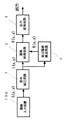
図1において、画像入力装置100として、例えば、デジタル・スチル・カメラ(以後、DSCと記す)を用いる。その出力G(x,y)の画像の明るさに対する信号歪みを、歪み補正回路1で補正を行い、その後、注視点I(x,y)とその周辺分布との明るさの相対比R(x,y)を計算する。周辺分布の明るさは、周辺輝度算出回路4により算出される。相対比R(x,y)は、出力変換回路3により最終の信号レベル(例えば、8ビットの0から255の信号レベル)に変換される。
In FIG. 1, for example, a digital still camera (hereinafter referred to as DSC) is used as the
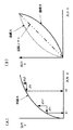
sRGB準拠の画像データやDSC画像データには、CRTディスプレイの発光特性の非線形性を予め補償するためにガンマ補正が加えられている。図2(A)に図示する曲線Aのような非線形な画像データに対し濃度調整を行う場合、撮影画像の明るさに対して画像処理の処理効果が違ってくる。これは、入力(X1)付近での明るさに対する変化度(Δy1/ΔX)と、入力(X2)での明るさに対する変化度(Δy2/ΔX)が異なるためである。この変化度の違いにより、画像に対する依存性が大きくなってしまう。DSC等の撮影画像に対し、自動的に濃度調整を行うには、画像に対する依存度が小さいほどよく、安定した画質が得られる。 The sRGB-compliant image data and DSC image data are subjected to gamma correction in order to compensate in advance for the nonlinearity of the light emission characteristics of the CRT display. When density adjustment is performed on nonlinear image data such as the curve A illustrated in FIG. 2A, the processing effect of image processing differs with respect to the brightness of the captured image. This is because the degree of change (Δy1 / ΔX) with respect to brightness near the input (X1) is different from the degree of change (Δy2 / ΔX) with respect to brightness at the input (X2). Due to this difference in the degree of change, the dependency on the image increases. In order to automatically adjust the density of a photographed image such as DSC, the smaller the degree of dependence on the image, the better and a stable image quality can be obtained.
そこで、図2(B)に図示するように、曲線Aの歪みをキャンセルするように、曲線Bの歪み補正を行えば、よりリニアな出力が得られる。例えば、sRGB、DSC等でγ=1/2.2に設定されていれば、画像データに対し、出力=(Vi1/2.2)2.2 =Viと逆γ=2.2の補正を歪み補正回路1で行うことで、リニアなオリジナル画像信号Viが出力として得られる。ここでは、逆γ変換により、リニアな信号に変換したが、入力信号が持つ非線形歪みを小さくすれば良く、同様の効果が得られる。よって、変換される値がリニアに限定されない。 Therefore, as shown in FIG. 2B, if the distortion of the curve B is corrected so as to cancel the distortion of the curve A, a more linear output can be obtained. For example, if γ = 1 / 2.2 is set in sRGB, DSC, or the like, the distortion correction circuit corrects output = (Vi 1 / 2.2 ) 2.2 = Vi and inverse γ = 2.2 for the image data. 1 is performed, the linear original image signal Vi is obtained as an output. Here, the signal is converted into a linear signal by inverse γ conversion. However, the nonlinear distortion of the input signal may be reduced, and the same effect can be obtained. Therefore, the value to be converted is not limited to linear.
周辺輝度算出回路4は、歪み補正された出力I(x,y)から、(数4)(数5)(数6)により注視点の周辺分布の明るさB[x,y]を算出する。ここで、*は畳み込み積分(Convolution)を表す。
The peripheral
画像処理回路2は、(数7)を用いて、線形レティネックス出力R(x,y)を算出する。
The
出力変換回路3は、図3に図示するようにR(x,y)の出力から所定の上限、下限の範囲を設定し、その範囲を所定の出力信号レベル(例えば、8bitの0〜255の信号レベル)に正規化して、ディスプレイ、プリンタ等に出力する。
As shown in FIG. 3, the
この線形レティネックスモデルでは、log変換を含まないため、高速な処理が可能である。また、画像中の明るさに対する出力変化が、どの明るさでも一定のため、画像依存性が小さい。 Since this linear Retinex model does not include log conversion, high-speed processing is possible. Further, since the output change with respect to the brightness in the image is constant at any brightness, the image dependency is small.
なお、周辺視野関数F(x,y)は、人間の視覚モデルとの対応から対象画素に近づくほど寄与する割合が高いガウス関数を用いたが、もともとボケ画像の明るさを算出するので、特性がフラットな矩形フィルタで代用してもよい。矩形フィルタを使用することで、処理速度を向上できる。 Note that the peripheral visual field function F (x, y) is a Gaussian function that contributes higher as it approaches the target pixel from the correspondence with the human visual model, but it originally calculates the brightness of the blurred image. May be replaced with a flat rectangular filter. The processing speed can be improved by using the rectangular filter.
また、線形モデルでは、基準輝度(A値)付近に出力画像の輝度を収束させる効果があり、白色、あるいは、白色に近い色の領域では、輝度が下がり、灰色として、知覚され、不自然さを感じる。そこで、図4に図示するように、曲線500の一定の輝度値SL以上をクリップして丸め込む(曲線501)ことで、ハイライト領域の輝度低下を防止する。結果、R(x,y)は(数8)ように改良される。
In addition, the linear model has an effect of converging the luminance of the output image near the reference luminance (A value). In the white or near-white color region, the luminance is lowered and perceived as gray, which is unnatural. Feel. Therefore, as shown in FIG. 4, the luminance of the highlight area is prevented from being lowered by clipping and rounding the
この輝度値の丸め処理プロセスをBAR(Blur After Round)プロセスと称する。なお、丸めのプロセスは(数9)のように、一旦、入力画像データI(x,y)とF(x,y)との畳み込み積分を行い、その出力に対してクリップ操作してもよい。この輝度値の丸め処理プロセスをBBR(Blur Before Round)プロセスと称する。 This luminance value rounding process is referred to as a BAR (Blur After Round) process. In the rounding process, as shown in (Equation 9), the input image data I (x, y) and F (x, y) may be temporarily integrated and clipped on the output. . This luminance value rounding process is referred to as a BBR (Blur Before Round) process.
図8に本発明の第1の実施の形態である画像処理装置の処理のフローチャート図を示す。図8において、ステップS101では入力画像データの歪みを補正する。DSCの画像データ歪みとは、sRGB準拠によるディスプレイγ値の歪み、CCD特性の歪み等である。ステップS103では歪み補正された画像データに対し、注視点(Center)とその周辺領域(Surround)との明るさの相対比を算出する。ステップS105では、算出し相対比を上限、下限で制限し、そのクリッピング範囲に対して最終の信号レベルを割り当てるように変換する。例えば、8ビットの0から255の信号レベルに割り振り、ディスプレイ、プリンタ等に出力する。ディスプレイの輝度特性を考慮する場合は、γ=1/2.2値を乗じて出力する。これにより、視覚的に輝度リニアな特性が得られる。ステップS107では、すべての画像データの処理が完了したかを判断し、完了の場合は処理を終了する。完了していない場合は、ステップS101に戻り、繰り返し処理を実行する。 FIG. 8 shows a flowchart of processing of the image processing apparatus according to the first embodiment of the present invention. In FIG. 8, in step S101, distortion of input image data is corrected. The image data distortion of DSC is distortion of display γ value based on sRGB, distortion of CCD characteristics, and the like. In step S103, the relative ratio of the brightness of the gazing point (Center) and the surrounding area (Surround) is calculated for the distortion-corrected image data. In step S105, the calculated relative ratio is limited by an upper limit and a lower limit, and conversion is performed so that the final signal level is assigned to the clipping range. For example, an 8-bit signal level from 0 to 255 is allocated and output to a display, a printer, or the like. When the luminance characteristic of the display is taken into consideration, the output is multiplied by γ = 1 / 2.2. Thereby, a visually luminance linear characteristic is obtained. In step S107, it is determined whether processing of all image data has been completed. If completed, the processing ends. If not completed, the process returns to step S101 and repeats the process.
以上のように、本発明の第1の実施の形態である画像処理方法及び装置よれば、処理系にlog変換を含まず、さらには、画像データの非線形歪みを小さくなるように補正することで、どの明るさのレベルでも同じような処理結果を得ることができる。結果、画像依存性が少なく、画像の暗部の画質調整を自動で調整できる。さらには、入力画像データの一定の輝度値以上をクリップして丸め込むことで、ハイライト領域の輝度の低下を防止する。 As described above, according to the image processing method and apparatus of the first embodiment of the present invention, the processing system does not include log conversion, and further, correction is performed so as to reduce nonlinear distortion of image data. Similar processing results can be obtained at any brightness level. As a result, there is little image dependency and the image quality adjustment in the dark part of the image can be automatically adjusted. Furthermore, by clipping and rounding a certain luminance value or more of the input image data, the luminance of the highlight area is prevented from being lowered.
(第2の実施の形態)
次に、本発明の第2の実施の形態である画像処理装置について説明する。図5は本発明の第2の実施の形態である画像処理装置のブロック図である。また、図6は本発明の第2の実施の形態である画像処理装置の周辺輝度算出回路9の説明図、図7は本発明の第2の実施の形態である画像処理装置のゲイン係数算出回路7の説明図である。なお、構成図の各図において、同一部には同じ番号を付している。また、これ以降で、画素位置(x,y)の単位には全て画素単位が用いられることする。
(Second Embodiment)
Next, an image processing apparatus according to the second embodiment of the present invention will be described. FIG. 5 is a block diagram of an image processing apparatus according to the second embodiment of the present invention. FIG. 6 is an explanatory diagram of the peripheral
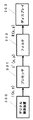
図5において、画像入力装置100として、例えば、デジタル・スチル・カメラ(以後、DSCと記す)を用いる。その出力G(x,y)の画像の明るさに対する信号歪みを、歪み補正回路1で補正を行い、その後、注視点I(x,y)とその周辺分布との明るさの相対比R(x,y)を計算する。カラーバランスを考慮して、単色化処理回路5でカラー信号を(数10)のように単色化して、単色化信号Y(x,y)から周辺輝度算出回路9により周辺分布の明るさが算出される。第2画像処理回路では、Ii(x,y)/{Fs(x,y)*Y(x,y)}に重み係数Wsとゲイン係数A(σs)を掛け合わせて合成した(数11)の相対比R(x,y)を出力する。合成された相対比R(x,y)は出力変換回路3により最終の信号レベル(例えば、8ビットの0から255の信号レベル)に変換される。ここで、Ws=1/M、σs=2m、A(σs)=σs/σM=2s-mである。
In FIG. 5, as the
周辺輝度算出回路9では、複数の視野関数Fs(x,y)出力を算出し、第2画像処理回路8で、異なる複数の視野関数Fs(x,y)出力から明るさの相対比を合成することで、画像依存性の少ないR(x,y)を算出できる。
The peripheral
視野関数Fs(x,y)は人間の視覚モデルとの対応から対象画素に近づくほど寄与する割合が高いガウス関数を用いても良いし、もともとボケ画像の明るさを算出するので、特性がフラットな矩形フィルタで代用してもよい。矩形フィルタとして、図6に図示するように対象とする画像領域のサイズが異なるフィルタ200〜フィルタ203を用いる。また、σ値の異なるガウス関数を用いても良い。図7に、σs値とゲイン係数Aとの関係を示す。ゲイン係数算出回路7は、σs値に応じて、ゲイン係数Aを算出する。
The visual field function Fs (x, y) may be a Gaussian function that contributes higher as it approaches the target pixel due to its correspondence with the human visual model, and the brightness of the blurred image is originally calculated, so the characteristics are flat. A rectangular filter may be used instead. As the rectangular filter, filters 200 to 203 having different image area sizes as shown in FIG. 6 are used. Further, Gaussian functions having different σ values may be used. FIG. 7 shows the relationship between the σs value and the gain coefficient A. The gain
図9に本発明の第2の実施の形態である画像処理装置の処理のフローチャート図を示す。図9において、ステップS201〜ステップS211は、図8に本発明の第1の実施の形態である画像処理装置のフローチャート図のステップS103の明るさの相対比を算出する部分の改良である。また、カラーに拡張したものである。ステップS201では歪み補正されたカラー画像データに対し、カラーバランスを考慮して、単色化処理を行う。単色信号Y(x,y)は、Y(x,y)=Kr×Ir(x,y)+Kg×Ig(x,y)+Kb×Ib(x,y)、Kr=0.299、Kg=0.587、Kb=0.114となる。 FIG. 9 shows a flowchart of processing of the image processing apparatus according to the second embodiment of the present invention. In FIG. 9, steps S201 to S211 are improvements of the portion for calculating the relative brightness ratio in step S103 of the flowchart of the image processing apparatus according to the first embodiment of the present invention shown in FIG. In addition, it is extended to color. In step S201, the color image data subjected to distortion correction is subjected to monochromatic processing in consideration of color balance. The monochrome signal Y (x, y) is Y (x, y) = Kr × Ir (x, y) + Kg × Ig (x, y) + Kb × Ib (x, y), Kr = 0.299, Kg = 0.587, Kb = 0.114.
ステップS203では、単色信号Y(x,y)から、異なる複数の視野関数Fs(x,y)を計算する。 In step S203, a plurality of different visual field functions Fs (x, y) are calculated from the monochromatic signal Y (x, y).
ステップS205では視野関数Fs(x,y)の領域の大きさに応じてゲイン係数A(σs)を計算する。例えば、A(σs)=σs/σM=2s-mである。 In step S205, a gain coefficient A (σs) is calculated according to the size of the area of the visual field function Fs (x, y). For example, A (σs) = σs / σ M = 2 sm .
ステップS207では視野関数Fs(x,y)の数Mによって均等分割された重み係数Ws値(Ws=1/M)を計算する。ステップS209ではIi(x,y)/{Fs(x,y)*Y(x,y)}に重み係数Wsとゲイン係数A(σs)を掛け合わせた明るさの相対比を計算する。ステップS211では、(数11)によって、明るさの相対比を合成した値を計算する。以上の処理が終了した時点で、図8に本発明の第1の実施の形態である画像処理装置のフローチャート図のステップS105に進み、合成された相対比を最終の信号レベルに変換する。例えば、8ビットの0から255の信号レベルでディスプレイ、プリンタ等に出力される。ディスプレイの輝度特性を考慮する場合は、γ=1/2.2値を乗じて出力する。これにより、視覚的に輝度リニアな特性が得られる。ステップS107では、すべての画像データの処理が完了したかを判断し、完了の場合は処理を終了する。完了していない場合は、ステップS101に戻り、繰り返し処理を実行する。ステップS103を実行する段階で、ステップS201に移行する。 In step S207, the weight coefficient Ws value (Ws = 1 / M) equally divided by the number M of the visual field functions Fs (x, y) is calculated. In step S209, a relative brightness ratio is calculated by multiplying Ii (x, y) / {Fs (x, y) * Y (x, y)} by the weighting coefficient Ws and the gain coefficient A (σs). In step S211, a value obtained by combining the relative ratios of brightness is calculated according to (Equation 11). When the above processing is completed, the process proceeds to step S105 in the flowchart of the image processing apparatus according to the first embodiment of the present invention shown in FIG. 8, and the combined relative ratio is converted to the final signal level. For example, an 8-bit signal level of 0 to 255 is output to a display, a printer, or the like. When the luminance characteristic of the display is taken into consideration, the output is multiplied by γ = 1 / 2.2. Thereby, a visually luminance linear characteristic is obtained. In step S107, it is determined whether processing of all image data has been completed. If completed, the processing ends. If not completed, the process returns to step S101 and repeats the process. In step S103, the process proceeds to step S201.
なお、ゲイン係数算出回路7は、σs値に応じたゲイン係数A(σs)を、ボケ画像Ss(x,y,σs)={Fs(x,y)*Y(x,y)}とした時の画像中の最大値Smax(s)と最小値Smin(s)から算出しても良い。例えば、A(σs)=Smin(s)/Smin(M)、A(σs)=1−0.5×{Smin(s)+Smax(s)}、A(σs)=1−Smax(s)等である。ここで、Mは視野関数Fsの数である。
The gain
以上のように、本発明の第2の実施の形態である画像処理方法及び装置よれば、複数の視野関数複数の視野関数Fs(x,y)出力を算出し、異なる複数の視野関数Fs(x,y)出力から得られる明るさの相対比を合成するので、画像依存性の少ない相対比R(x,y)を算出できる。 As described above, according to the image processing method and apparatus of the second embodiment of the present invention, outputs of a plurality of field functions Fs (x, y) are calculated, and a plurality of different field functions Fs ( Since the relative ratio of brightness obtained from the x, y) output is synthesized, the relative ratio R (x, y) with little image dependency can be calculated.
また、相対比の算出には、カラー画像を一旦、単色化して、そのボケ画像を使用するので、R,G,Bを独立して別々に相対比を算出するよりカラーバランスを保持できる。結果、画像の暗部の見えを改善しながら、画像依存することなく、画像中の濃度値を自動で調整できる。 In calculating the relative ratio, the color image is once converted into a single color and the blurred image is used, so that the color balance can be maintained rather than calculating the relative ratio of R, G, and B separately. As a result, it is possible to automatically adjust the density value in the image without depending on the image while improving the appearance of the dark part of the image.
なお、上記した実施の形態1および2においては、画像入力手段から入力された全ての画像データに対して、信号補正手段(歪み補正回路)により、非線形性が小さくなるように補正するように構成していたが、これに限定されるものではない。 In the first and second embodiments described above, all image data input from the image input unit is corrected by the signal correction unit (distortion correction circuit) so as to reduce nonlinearity. However, it is not limited to this.
すなわち、歪み補正は、非線形な歪み、明るさに対しカンマ値を有するデバイス、または画像ファイルに適用すれば良く、線形なデバイス、ガンマ補正の必要ない画像ファイルでは適用する必要はない。このため、予め、デバイスに非線形な歪みが存在するのか、あるいは画像ファイルにガンマ値が存在するのかを歪み判定手段により判定し、歪みを有する入力画像に対して、歪み補正回路により、歪み補正を選択的に適用するように構成することもできる。この判定情報として、例えば、カメラの画像ファイル規格に記載されているsRBG等のカラースペース情報、ガンマ情報がある。これにより、自動的にデバイス歪み、画像ファイルのガンマ値を補正できる。 In other words, distortion correction may be applied to a device having a comma value with respect to non-linear distortion and brightness, or an image file, and need not be applied to a linear device or an image file that does not require gamma correction. For this reason, it is determined in advance by the distortion determination means whether nonlinear distortion exists in the device or a gamma value exists in the image file, and distortion correction is performed on the input image having distortion by the distortion correction circuit. It can also be configured to be selectively applied. Examples of the determination information include color space information such as sRBG and gamma information described in the camera image file standard. As a result, the device distortion and the gamma value of the image file can be automatically corrected.
なお、本発明の処理は、画像処理方法に従いコンピュータ等に使用される中央演算処理装置(CPU)及びデジタルシグナルプロセッサ(DSP)等を使ったソフトウェア処理でも同様に実現することができる。 The processing of the present invention can be similarly realized by software processing using a central processing unit (CPU) and a digital signal processor (DSP) used in a computer or the like according to an image processing method.
また、外部から通信回線を経由してソフトウェア媒体としてダウンロードを行い、ローカルなコンピュータの中でのソフトウェア処理でも同様に実現することができる。 Moreover, it can be similarly implemented by software processing in a local computer by downloading as a software medium from the outside via a communication line.
以上のように、本発明によれば、撮像画像対象に依存せず、自動的に画像の濃淡値を調整できる。 As described above, according to the present invention, the gray value of the image can be automatically adjusted without depending on the captured image object.
特に、本発明の第1の実施の形態である画像処理方法及び装置よれば、処理系にlog変換を含まず、さらには、画像データの非線形歪みを小さくなるように補正することで、どの明るさのレベルでも同じような処理結果を得ることができる。結果、画像依存性の少ない、画像の暗部の画質調整を自動で行うことができる。さらには、入力画像データの一定の輝度値以上をクリップして丸め込むことで、ハイライト領域の輝度の低下を防止する。 In particular, according to the image processing method and apparatus of the first embodiment of the present invention, the processing system does not include log conversion, and further, by correcting so that nonlinear distortion of the image data is reduced, Similar processing results can be obtained at this level. As a result, it is possible to automatically perform image quality adjustment in a dark part of an image with little image dependency. Furthermore, by clipping and rounding a certain luminance value or more of the input image data, the luminance of the highlight area is prevented from being lowered.
また、本発明の第2の実施の形態である画像処理方法及び装置よれば、複数の視野関数複数の視野関数Fs(x,y)出力を算出し、異なる複数の視野関数Fs(x,y)出力から得られる明るさの相対比を合成するので、画像依存性の少ない相対比R(x,y)を算出できる。 In addition, according to the image processing method and apparatus of the second embodiment of the present invention, outputs of a plurality of field functions Fs (x, y) are calculated, and a plurality of different field functions Fs (x, y) are calculated. ) Since the relative brightness ratio obtained from the output is synthesized, the relative ratio R (x, y) with little image dependence can be calculated.
また、相対比の算出には、カラー画像を一旦、単色化して、そのボケ画像を使用するので、R,G,Bを独立して別々に相対比を算出するよりカラーバランスを保持できる。結果、画像の暗部の見えを改善しながら、画像依存することなく、画像中の濃度値を自動で調整できる。 In calculating the relative ratio, the color image is once converted into a single color and the blurred image is used, so that the color balance can be maintained rather than calculating the relative ratio of R, G, and B separately. As a result, it is possible to automatically adjust the density value in the image without depending on the image while improving the appearance of the dark part of the image.
1 歪み補正回路
2 画像処理回路
3 出力変換回路
4 周辺輝度算出回路
5 単色化回路
6 重み係数
7 ゲイン係数算出回路
8 第2画像処理回路
300 ディジタル撮像装置
301 プロセッサ
302 フィルタ
303 ディスプレイ
DESCRIPTION OF
Claims (3)
入力画像の非線形歪の有無を判定する判定回路と、A determination circuit for determining the presence or absence of nonlinear distortion in the input image;
前記判定回路の判定に応じて入力画像値の非線形歪を補正する信号補正回路と、A signal correction circuit for correcting nonlinear distortion of the input image value in accordance with the determination of the determination circuit;
前記信号補正回路からの補正輝度値をもとに、着目画素の周辺分布領域の画素の補正輝度値を平滑化する周辺輝度算出回路と、 Based on the corrected luminance value from the signal correcting circuit, a peripheral luminance calculating circuit that smoothes the corrected luminance value of the pixels in the peripheral distribution region of the target pixel;
前記平滑化された周辺分布領域の補正輝度値と着目画素の補正輝度値との相対比に The relative ratio between the corrected luminance value of the smoothed peripheral distribution region and the corrected luminance value of the pixel of interest
基づいて、所定のゲイン係数を乗じる第2画像処理回路と、A second image processing circuit for multiplying by a predetermined gain coefficient,
該周辺分布領域のサイズに応じて前記ゲイン係数を決定するゲイン係数算出回路と、A gain coefficient calculation circuit for determining the gain coefficient according to the size of the peripheral distribution region;
前記第2画像処理回路で得られた値を出力デバイスの信号レベルに正規化して出力する出力変換回路と、An output conversion circuit that normalizes and outputs the value obtained by the second image processing circuit to the signal level of the output device;
を備える画像処理プロセッサ。An image processor.
前記ゲイン係数算出回路は、前記周辺分布領域のサイズが大きいほど、前記ゲイン係数の値を大きく決定する請求項1記載の画像処理のプロセッサ。The image processing processor according to claim 1, wherein the gain coefficient calculation circuit determines the gain coefficient value to be larger as the size of the peripheral distribution region is larger.
Priority Applications (1)
| Application Number | Priority Date | Filing Date | Title |
|---|---|---|---|
| JP2007104801A JP4488024B2 (en) | 2007-04-12 | 2007-04-12 | Image processing apparatus and image processing method |
Applications Claiming Priority (1)
| Application Number | Priority Date | Filing Date | Title |
|---|---|---|---|
| JP2007104801A JP4488024B2 (en) | 2007-04-12 | 2007-04-12 | Image processing apparatus and image processing method |
Related Parent Applications (1)
| Application Number | Title | Priority Date | Filing Date |
|---|---|---|---|
| JP2002135160A Division JP4096613B2 (en) | 2002-05-10 | 2002-05-10 | Image processing method and image processing apparatus |
Publications (3)
| Publication Number | Publication Date |
|---|---|
| JP2007193844A JP2007193844A (en) | 2007-08-02 |
| JP2007193844A5 JP2007193844A5 (en) | 2007-11-15 |
| JP4488024B2 true JP4488024B2 (en) | 2010-06-23 |
Family
ID=38449431
Family Applications (1)
| Application Number | Title | Priority Date | Filing Date |
|---|---|---|---|
| JP2007104801A Expired - Lifetime JP4488024B2 (en) | 2007-04-12 | 2007-04-12 | Image processing apparatus and image processing method |
Country Status (1)
| Country | Link |
|---|---|
| JP (1) | JP4488024B2 (en) |
-
2007
- 2007-04-12 JP JP2007104801A patent/JP4488024B2/en not_active Expired - Lifetime
Also Published As
| Publication number | Publication date |
|---|---|
| JP2007193844A (en) | 2007-08-02 |
Similar Documents
| Publication | Publication Date | Title |
|---|---|---|
| EP2076013B1 (en) | Method of high dynamic range compression | |
| JP4577621B2 (en) | Image correction processing system and image correction processing method | |
| EP2160020B1 (en) | Image processing apparatus for performing gradation correction on subject image | |
| JP4076302B2 (en) | Image brightness correction method | |
| JP4210577B2 (en) | Method for enhancing gradation and spatial characteristics of digital images using selective spatial filters | |
| JP4096613B2 (en) | Image processing method and image processing apparatus | |
| JP5392560B2 (en) | Image processing apparatus and image processing method | |
| JP6097588B2 (en) | Image processing apparatus and image processing method | |
| JP5235759B2 (en) | Image processing apparatus, image processing method, and program | |
| JP4021261B2 (en) | Image processing device | |
| JPWO2009072537A1 (en) | Image processing apparatus and method, program, and recording medium | |
| JP2001216512A (en) | Method for improving digital images with noise-dependent control of texture | |
| JP4526445B2 (en) | Imaging device | |
| JP2001216511A (en) | Method for improving edge contrast of digital picture independently of texture | |
| CN106575434A (en) | Image processing device, image capturing device, image processing method, and program | |
| JP4497959B2 (en) | Video signal processing apparatus and video signal processing method | |
| JP4664938B2 (en) | Image processing apparatus, image processing method, and program | |
| JP5410378B2 (en) | Video signal correction apparatus and video signal correction program | |
| JP4479527B2 (en) | Image processing method, image processing apparatus, image processing program, and electronic camera | |
| JP2002281312A (en) | Device, method and program for processing image | |
| JP2006114005A (en) | Gradation conversion device, program, electronic camera, and method thereof | |
| JP5234127B2 (en) | Gradation conversion device, program, electronic camera, and method thereof | |
| JP4273748B2 (en) | Image processing apparatus and method | |
| JP5295854B2 (en) | Image processing apparatus and image processing program | |
| JP4488024B2 (en) | Image processing apparatus and image processing method |
Legal Events
| Date | Code | Title | Description |
|---|---|---|---|
| A521 | Request for written amendment filed |
Free format text: JAPANESE INTERMEDIATE CODE: A523 Effective date: 20071002 |
|
| RD01 | Notification of change of attorney |
Free format text: JAPANESE INTERMEDIATE CODE: A7421 Effective date: 20091127 |
|
| A977 | Report on retrieval |
Free format text: JAPANESE INTERMEDIATE CODE: A971007 Effective date: 20100224 |
|
| TRDD | Decision of grant or rejection written | ||
| A01 | Written decision to grant a patent or to grant a registration (utility model) |
Free format text: JAPANESE INTERMEDIATE CODE: A01 Effective date: 20100309 |
|
| A01 | Written decision to grant a patent or to grant a registration (utility model) |
Free format text: JAPANESE INTERMEDIATE CODE: A01 |
|
| A61 | First payment of annual fees (during grant procedure) |
Free format text: JAPANESE INTERMEDIATE CODE: A61 Effective date: 20100322 |
|
| FPAY | Renewal fee payment (event date is renewal date of database) |
Free format text: PAYMENT UNTIL: 20130409 Year of fee payment: 3 |
|
| FPAY | Renewal fee payment (event date is renewal date of database) |
Free format text: PAYMENT UNTIL: 20130409 Year of fee payment: 3 |
|
| FPAY | Renewal fee payment (event date is renewal date of database) |
Free format text: PAYMENT UNTIL: 20130409 Year of fee payment: 3 |
|
| FPAY | Renewal fee payment (event date is renewal date of database) |
Free format text: PAYMENT UNTIL: 20140409 Year of fee payment: 4 |