JP4487583B2 - Cam member and recording apparatus including the cam member - Google Patents

Cam member and recording apparatus including the cam member Download PDF

Info

Publication number
JP4487583B2
JP4487583B2 JP2004029850A JP2004029850A JP4487583B2 JP 4487583 B2 JP4487583 B2 JP 4487583B2 JP 2004029850 A JP2004029850 A JP 2004029850A JP 2004029850 A JP2004029850 A JP 2004029850A JP 4487583 B2 JP4487583 B2 JP 4487583B2
Authority
JP
Japan
Prior art keywords
recording material
cam
recording
platen
alignment plate
Prior art date
Legal status (The legal status is an assumption and is not a legal conclusion. Google has not performed a legal analysis and makes no representation as to the accuracy of the status listed.)
Expired - Fee Related
Application number
JP2004029850A
Other languages
Japanese (ja)
Other versions
JP2005221011A (en
Inventor
政昭 中村
Current Assignee (The listed assignees may be inaccurate. Google has not performed a legal analysis and makes no representation or warranty as to the accuracy of the list.)
Seiko Epson Corp
Original Assignee
Seiko Epson Corp
Priority date (The priority date is an assumption and is not a legal conclusion. Google has not performed a legal analysis and makes no representation as to the accuracy of the date listed.)
Filing date
Publication date
Application filed by Seiko Epson Corp filed Critical Seiko Epson Corp
Priority to JP2004029850A priority Critical patent/JP4487583B2/en
Priority to CNB2005100064517A priority patent/CN100345689C/en
Publication of JP2005221011A publication Critical patent/JP2005221011A/en
Application granted granted Critical
Publication of JP4487583B2 publication Critical patent/JP4487583B2/en
Anticipated expiration legal-status Critical
Expired - Fee Related legal-status Critical Current

Links

Images

Description

本発明は、カム部材、及び当該カム部材を備えた記録装置に関する。特に本発明は、カム部材を備え、磁気ストライプが取り付けられた被記録物を磁気ヘッドと対向する位置に搬送して磁気の読み書きを行う記録装置に関する。   The present invention relates to a cam member and a recording apparatus including the cam member. In particular, the present invention relates to a recording apparatus that reads and writes magnetism by conveying a recording material that includes a cam member and to which a magnetic stripe is attached to a position facing a magnetic head.

従来、磁気ストライプが取り付けられた被記録物を磁気ヘッドと対向する位置に搬送して磁気の読み書きを行う記録装置がある。この様な記録装置は、挿入された被記録物をまず搬送ローラで送り、被記録物の先端を整列板に押し当てることによりスキューを補正する。その後、被記録物を下方から支持する可動紙案内を搬送経路に進出させた状態で、磁気ストライプが磁気ヘッドと対向する位置まで被記録物を搬送する。次に、可動紙案内を搬送経路から下方に退避させることによって、磁気ヘッドの走査経路を確保し、同時に、被記録物押さえによって被記録物を磁気ヘッドの方に押しあてる(例えば、特許文献1、及び特許文献2参照。)。
US6499895、Fig.10 特開2002−36658号公報、図5
2. Description of the Related Art Conventionally, there is a recording apparatus that reads and writes magnetism by transporting a recording material to which a magnetic stripe is attached to a position facing a magnetic head. Such a recording apparatus first corrects the skew by feeding the inserted recording object with a conveying roller and pressing the leading end of the recording object against the alignment plate. Thereafter, the recording material is transported to a position where the magnetic stripe faces the magnetic head in a state where the movable paper guide supporting the recording material from below is advanced in the transport path. Next, the scanning path of the magnetic head is secured by retracting the movable paper guide downward from the conveyance path, and at the same time, the recording material is pressed toward the magnetic head by pressing the recording material (for example, Patent Document 1). And Patent Document 2).
US6499895, FIG. 10 Japanese Patent Laid-Open No. 2002-36658, FIG.

従来は、上記一連の動作を実現する為に、多くの構成部品でリンク機構を構成していた。従って、リンク機構の占有スペースが大きく、小型で低コストの記録装置を実現することが困難であるという課題があった。   Conventionally, in order to realize the above-described series of operations, a link mechanism is constituted by a number of components. Accordingly, there is a problem that it is difficult to realize a small and low-cost recording apparatus with a large space occupied by the link mechanism.

上記課題を解決するために、本発明の第1の形態において、回転軸を中心に回転する板状のカム部材は、回転軸の方向における両面にカム溝又はカムリブが設けられている。これにより、一つのカム部材で2以上の従節を駆動することができる。   In order to solve the above-described problem, in the first embodiment of the present invention, the plate-like cam member that rotates about the rotation shaft is provided with cam grooves or cam ribs on both surfaces in the direction of the rotation shaft. Thereby, two or more followers can be driven by one cam member.

カム部材は、同一の方向に回転することにより、両面に設けられたカム溝又はカムリブのそれぞれの従節を異なるタイミングで駆動し始めてもよい。これにより、2以上の従節のそれぞれを駆動する場合の負荷が分散されるので、出力の小さな動力源を使用できる。   The cam member may start to drive the followers of the cam grooves or cam ribs provided on both surfaces at different timings by rotating in the same direction. As a result, the load when driving each of the two or more followers is distributed, so that a power source having a small output can be used.

本発明の第2の形態によれば、磁気ストライプが取り付けられた被記録物を磁気ヘッドと対向する位置に搬送して磁気の読み書きを行う記録装置は、被記録物の搬送経路を遮る位置に進出し、被記録物の先端を当接させることにより被記録物の向きを揃える整列板と、磁気ヘッドが磁気ストライプを走査する場合に、被記録物を磁気ヘッドに押し当てる被記録物押さえと、回転軸を中心に回転する板状のカム部材であって、回転軸の方向における両面に設けられたカム溝又はカムリブの一方で整列板を動作させ、他方で被記録物押さえを動作させるカム部材とを備える。これにより、整列板と被記録物押さえとを同一のカム部材で動作させることができるので、省スペース化と部品コストの削減が実現される。従って、小型で低コストな記録装置を提供できる。   According to the second aspect of the present invention, the recording apparatus for reading and writing magnetism by transporting the recording material with the magnetic stripe attached to the position facing the magnetic head is located at a position that blocks the recording material transport path. An alignment plate for advancing and aligning the direction of the recording material by abutting the tip of the recording material, and a recording material presser for pressing the recording material against the magnetic head when the magnetic head scans the magnetic stripe; , A plate-like cam member that rotates about a rotation axis, and operates an alignment plate on one of cam grooves or cam ribs provided on both surfaces in the direction of the rotation axis, and operates a recording material presser on the other side A member. As a result, the alignment plate and the recording material presser can be operated by the same cam member, so that space saving and part cost reduction are realized. Therefore, a small and low cost recording apparatus can be provided.

上記記録装置において、カム部材は、同一の方向に回転することによって、整列板及び被記録物押さえを異なるタイミングで駆動し始めてもよい。これにより、動力源への負荷が分散され、動力源を小型化できる。   In the recording apparatus, the cam member may start to drive the alignment plate and the recording material holder at different timings by rotating in the same direction. Thereby, the load to a power source is distributed and a power source can be reduced in size.

本発明の第3の形態によれば、磁気ストライプが取り付けられた被記録物を磁気ヘッドと対向する位置に搬送して磁気の読み書きを行う記録装置は、被記録物の搬送経路を遮る位置に進出し、被記録物の先端を当接させることにより被記録物の向きを揃える整列板と、被記録物が搬送される場合に被記録物の搬送係路に進出して被記録物を支持し、磁気ヘッドが磁気ストライプを走査する場合に搬送経路から退避する可動紙案内と、回転軸を中心に回転する板状のカム部材であって、回転軸の方向における両面に設けられたカム溝又はカムリブの一方で整列板を動作させ、他方で可動紙案内を動作させるカム部材とを備える。これにより、整列板と可動紙案内とを同一のカム部材で動作させることができるので、省スペース化と部品コストの削減が実現される。従って、小型で低コストな記録装置を提供できる。   According to the third aspect of the present invention, the recording apparatus for reading and writing magnetism by transporting the recording material with the magnetic stripe attached to the position facing the magnetic head is located at a position that blocks the transport path of the recording material. Alignment plate that aligns the orientation of the recording material by advancing and bringing the leading edge of the recording material into contact with each other, and when the recording material is conveyed, it advances to the conveyance path of the recording material to support the recording material And a movable paper guide that retreats from the conveyance path when the magnetic head scans the magnetic stripe, and a plate-like cam member that rotates about the rotation axis, and cam grooves provided on both surfaces in the direction of the rotation axis. Alternatively, a cam member that operates the alignment plate on one side of the cam rib and operates the movable paper guide on the other side is provided. Thereby, since the alignment plate and the movable paper guide can be operated by the same cam member, space saving and part cost reduction are realized. Therefore, a small and low cost recording apparatus can be provided.

上記記録装置において、カム部材は、同一の方向に回転することによって、整列板及び可動紙案内を異なるタイミングで駆動し始めてもよい。これにより、動力源への負荷が分散され、動力源を小型化できる。   In the recording apparatus, the cam member may start to drive the alignment plate and the movable paper guide at different timings by rotating in the same direction. Thereby, the load to a power source is distributed and a power source can be reduced in size.

本発明の第4の形態によれば、磁気ストライプが取り付けられた被記録物を磁気ヘッドと対向する位置に搬送して磁気の読み書きを行う記録装置は、被記録物の搬送経路を遮る位置に進出し、被記録物の先端を当接させることにより被記録物の向きを揃える整列板と、磁気ヘッドが磁気ストライプを走査する場合に、被記録物を磁気ヘッドに押し当てる被記録物押さえと、被記録物が搬送される場合に被記録物の搬送係路に進出して被記録物を支持し、磁気ヘッドが磁気ストライプを走査する場合に搬送経路から退避する可動紙案内と、回転軸を中心に回転する板状のカム部材であって、回転軸の方向における両面に設けられたカム溝又はカムリブの一方で整列板を動作させ、他方で被記録物押さえ及び可動紙案内を動作させるカム部材とを備える。これにより、整列板、可動紙案内、及び被記録物押さえを同一のカム部材で動作させることができるので、省スペース化と部品コストの削減が実現される。従って、小型で低コストな記録装置を提供できる。   According to the fourth aspect of the present invention, the recording apparatus that reads and writes magnetism by transporting the recording object with the magnetic stripe attached to a position facing the magnetic head is located at a position that blocks the recording material transport path. An alignment plate for advancing and aligning the direction of the recording material by bringing the leading edge of the recording material into contact; and a recording material presser for pressing the recording material against the magnetic head when the magnetic head scans the magnetic stripe; A movable paper guide that moves forward to support the recording material when the recording material is conveyed and supports the recording material, and retracts from the conveyance path when the magnetic head scans the magnetic stripe; Is a plate-like cam member that rotates about the center of the rotation axis, and the alignment plate is operated on one of the cam grooves or the cam ribs provided on both surfaces in the direction of the rotation axis, and the recording material presser and the movable paper guide are operated on the other side. With cam member Obtain. Thereby, the alignment plate, the movable paper guide, and the recording material presser can be operated by the same cam member, so that space saving and part cost reduction are realized. Therefore, a small and low cost recording apparatus can be provided.

上記記録装置は、カム部材を同一の方向に回転させることにより、搬送経路を遮る位置に整列板を進出させ、且つ被記録物押さえによる被記録物の押さえを解放し、且つ可動紙案内を搬送経路に進出させる第1の状態と、搬送経路から整列板を退避させ、且つ被記録物押さえによる被記録物の押さえを解放し、且つ可動紙案内を搬送経路に進出させる第2の状態と、搬送経路から整列板を退避させ、且つ被記録物押さえを被記録物に押し当て、且つ可動紙案内を搬送経路から退避させる第3の状態とをこの順序で切り替え、第1の状態において被記録物の向きを揃え、第2の状態において磁気ストライプが磁気ヘッドに対向する位置まで被記録物を搬送し、第3の状態において磁気ヘッドで磁気ストライプを走査してもよい。これにより、整列板、被記録物押さえ、及び可動紙案内のそれぞれの状態の組み合わせから成る3つの搬送状態を同一のカム部材の単純な動作で切り替えることにより、磁気ストライプを精度良く読み書きする記録装置が実現される。従って、記録装置の低コストか、小型化が実現される。   The recording apparatus rotates the cam member in the same direction to advance the alignment plate to a position that interrupts the conveyance path, releases the recording material pressing by the recording material pressing, and conveys the movable paper guide. A first state of advancing to the path, a second state of retracting the alignment plate from the conveyance path, releasing the recording material by pressing the recording material, and advancing the movable paper guide to the conveyance path; The third state in which the alignment plate is retracted from the conveyance path, the recording material presser is pressed against the recording material, and the movable paper guide is retracted from the conveyance path is switched in this order, and recording is performed in the first state. The direction of the object may be aligned, the recording material may be conveyed to a position where the magnetic stripe faces the magnetic head in the second state, and the magnetic stripe may be scanned with the magnetic head in the third state. As a result, a recording apparatus that reads and writes the magnetic stripe with high accuracy by switching the three conveying states composed of combinations of the alignment plate, the recording material presser, and the movable paper guide by a simple operation of the same cam member. Is realized. Therefore, the cost of the recording apparatus can be reduced or the size can be reduced.

なお、上記の発明の概要は、本発明の必要な特徴の全てを列挙したものではなく、これらの特徴群のサブコンビネーションもまた、発明となりうる。   The above summary of the invention does not enumerate all the necessary features of the present invention, and sub-combinations of these feature groups can also be the invention.

以下、発明の実施の形態を通じて本発明を説明するが、以下の実施形態は特許請求の範囲にかかる発明を限定するものではなく、また実施形態の中で説明されている特徴の組み合わせの全てが発明の解決手段に必須であるとは限らない。   Hereinafter, the present invention will be described through embodiments of the invention. However, the following embodiments do not limit the invention according to the scope of claims, and all combinations of features described in the embodiments are included. It is not necessarily essential for the solution of the invention.

図1から図4は、本発明の実施形態に係る記録装置10の全体を説明する図である。図1は、記録装置10の外観を示す正面斜視図である。図1に示す記録装置10は、上部カバー12、上部ハウジング13および下部ハウジング14を有し、前面には、開口した挿入口18が設けられている。この挿入口18へ被記録物100が挿入されると、記録装置10により被記録物100に記録が行われ、被記録物100が挿入口18から排出される。被記録物100が詰まった場合の処置等のために、上部カバー12は取り外すことができるようになっている。ここで、被記録物100は、所定の長さに裁断された単票紙、フィルム、複数枚の用紙が重ね合わされた複写紙、通帳などである。以下、被記録物100の一例として、複数の記録用紙が綴じられ、記録用紙の記録面を開いた場合の底面に磁気ストライプ110が設けられた通帳を用いて記録装置10を説明する。   1 to 4 are diagrams illustrating the entire recording apparatus 10 according to the embodiment of the present invention. FIG. 1 is a front perspective view showing the external appearance of the recording apparatus 10. The recording apparatus 10 shown in FIG. 1 has an upper cover 12, an upper housing 13, and a lower housing 14, and an opening 18 is provided on the front surface. When the recording material 100 is inserted into the insertion port 18, recording is performed on the recording material 100 by the recording device 10, and the recording material 100 is discharged from the insertion port 18. The upper cover 12 can be removed for the treatment when the recording material 100 is jammed. Here, the recording object 100 is a cut sheet, a film, a copy sheet in which a plurality of sheets are overlapped, a passbook, or the like cut into a predetermined length. Hereinafter, as an example of the recording object 100, the recording apparatus 10 will be described using a bankbook in which a plurality of recording sheets are bound and a recording surface of the recording sheet is opened and a magnetic stripe 110 is provided on the bottom surface.

図2は、記録装置10から上部カバー12、上部ハウジング13および下部ハウジング14を取り外した状態を示す斜視図である。図3は、図2からさらに、被記録物押さえ部32およびリボンカセット60を取り外し、本体上部16を開いた状態を示す斜視図である。図4は、図1の記録装置10を被記録物100の搬送方向に沿って上下に切った断面図である。   FIG. 2 is a perspective view showing a state in which the upper cover 12, the upper housing 13 and the lower housing 14 are removed from the recording apparatus 10. FIG. 3 is a perspective view showing a state in which the recording material pressing portion 32 and the ribbon cassette 60 are further removed from FIG. FIG. 4 is a cross-sectional view of the recording apparatus 10 of FIG. 1 cut up and down along the conveyance direction of the recording material 100.

図2から図4に示すように、記録装置10は、挿入口18から挿入された被記録物100を搬送する搬送部30と、磁気情報読み書き時に被記録物100の浮き上がりを上から押さえる被記録物押さえ部32と、被記録物100に設けられた磁気ストライプ110の磁気情報を読み取りまたは書き込む磁気データ読取部40と、被記録物100を下方から支持するプラテン部50と、プラテン部50に対向して配され、リボンカセット60を用いて被記録物100に記録を行う記録部20とを備える。図3に示すように、プラテン部50が配される本体部11に対し、記録部20が配された本体上部16は開閉することができ、被記録物100が本体部11と本体上部16との間において詰まった場合にも被記録物100を容易に取り除くことができる。   As shown in FIGS. 2 to 4, the recording apparatus 10 includes a conveyance unit 30 that conveys the recording material 100 inserted from the insertion port 18 and a recording material that suppresses the lifting of the recording material 100 from above when reading / writing magnetic information. The object pressing unit 32, the magnetic data reading unit 40 that reads or writes the magnetic information of the magnetic stripe 110 provided on the recording object 100, the platen unit 50 that supports the recording object 100 from below, and the platen unit 50 are opposed to each other. And a recording unit 20 that performs recording on the recording object 100 using the ribbon cassette 60. As shown in FIG. 3, the main body upper part 16 provided with the recording part 20 can be opened and closed with respect to the main body part 11 provided with the platen part 50, and the recording object 100 is connected to the main body part 11 and the main body upper part 16. Even when the recording medium is jammed, the recording material 100 can be easily removed.

図4に示すように、搬送部30は、記録部20よりも手前で本体部11に支持されたフロント加圧部300と、このフロント加圧部300の下方に対向して本体部11に配されたフロント搬送部320と、これらフロント加圧部300およびフロント搬送部320よりも奥側であってプラテン部50の手前に配され、被記録物100の搬送経路に進退自在な整列板360と、記録部20よりも奥側の本体上部16に支持されたリア加圧部302と、このリア加圧部302の下方に対向して本体部11に配されたリア搬送部322とを有する。   As shown in FIG. 4, the transport unit 30 is arranged on the main body unit 11 so as to be opposed to the front pressurizing unit 300 supported by the main body unit 11 before the recording unit 20 and below the front pressurizing unit 300. A front conveying unit 320, and an alignment plate 360 which is arranged behind the platen unit 50 and behind the front pressure unit 300 and the front conveying unit 320, and is movable forward and backward in the conveying path of the recording material 100. A rear pressure unit 302 supported by the main body upper portion 16 on the back side of the recording unit 20, and a rear transport unit 322 disposed in the main body unit 11 so as to face the lower side of the rear pressure unit 302.

記録装置10の動作の概略を説明する。まず、被記録物100が挿入口18から挿入されると、フロント加圧部300とフロント搬送部320とが、被記録物100を挟んでプラテン部50の手前まで搬送する。その位置において、被記録物100の搬送方向の傾きを直すべく、被記録物100が整列される。被記録物100が整列された後に、被記録物100の底面に配された磁気ストライプ110が磁気データ読取部40により読み取られる読み取り位置まで、搬送部30が被記録物100を搬送する。その後、磁気データ読取部40が、本体前部17の長手方向(図2における左右方向)に移動して被記録物100の底面に配された磁気ストライプ110から磁気情報を読み取る。さらに、搬送部30が被記録物100をプラテン部50上の記録位置まで搬送する。磁気データ読取部40により読み取られた磁気情報に基づいて、記録部20は、被記録物100上を本体部11の長手方向(図2における左右方向)に移動しつつ、プラテン部50上に搬送された被記録物100へ、リボンカセット60のインクリボンを介して記録部20のワイヤを打ち当てることにより、被記録物100へ文字などの記録を行う。その後、上記読み取り位置まで、搬送部30が被記録物100を搬送する。被記録物100へ記録した情報に基づいて、磁気データ読取部40が、本体前部17の長手方向を再度移動して、磁気ストライプ110に磁気情報を書き込む。次に、搬送部30が被記録物100を手前側に搬送し、被記録物100を挿入口18から排出する。   An outline of the operation of the recording apparatus 10 will be described. First, when the recording material 100 is inserted from the insertion port 18, the front pressurization unit 300 and the front conveyance unit 320 convey the recording material 100 to the front of the platen unit 50. At that position, the recording material 100 is aligned in order to correct the inclination of the recording material 100 in the transport direction. After the recording object 100 is aligned, the conveyance unit 30 conveys the recording object 100 to a reading position where the magnetic data reading unit 40 reads the magnetic stripe 110 disposed on the bottom surface of the recording object 100. Thereafter, the magnetic data reading unit 40 moves in the longitudinal direction (left and right direction in FIG. 2) of the main body front portion 17 to read magnetic information from the magnetic stripe 110 disposed on the bottom surface of the recording material 100. Further, the conveyance unit 30 conveys the recording material 100 to a recording position on the platen unit 50. Based on the magnetic information read by the magnetic data reading unit 40, the recording unit 20 is conveyed on the platen unit 50 while moving on the recording material 100 in the longitudinal direction of the main body unit 11 (left and right direction in FIG. 2). Characters and the like are recorded on the recording object 100 by hitting the wire of the recording unit 20 to the recorded object 100 via the ink ribbon of the ribbon cassette 60. Thereafter, the conveyance unit 30 conveys the recording material 100 to the reading position. Based on the information recorded on the recording object 100, the magnetic data reading unit 40 moves again in the longitudinal direction of the main body front portion 17 and writes the magnetic information on the magnetic stripe 110. Next, the transport unit 30 transports the recording material 100 to the near side, and discharges the recording material 100 from the insertion port 18.

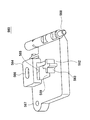
図5は、磁気データ読取部40が配された本体前部17を示す斜視図である。磁気データ読取部40は、本体前部17の長手方向に平行に渡された二本の磁気ヘッドガイド軸470、472と、これら磁気ヘッドガイド軸470、472に支持され、本体前部17の長手方向(図中の矢印Aの方向)に往復移動する磁気ヘッドユニット400と、磁気ヘッドユニット400に一部が固定された磁気ヘッド駆動ベルト480と、磁気ヘッドユニット400を往復移動すべく磁気ヘッド駆動ベルト480を回転駆動する磁気ヘッドモータ420と、磁気ヘッドモータ420の近傍で本体前部17の下部に配された制御基板440と、磁気ヘッドユニット400と制御基板440とを電気的に接続するフレキシブルケーブル450とを備える。   FIG. 5 is a perspective view showing the main body front part 17 in which the magnetic data reading part 40 is arranged. The magnetic data reading unit 40 is supported by two magnetic head guide shafts 470 and 472 that are passed in parallel with the longitudinal direction of the main body front portion 17, and these magnetic head guide shafts 470 and 472. Magnetic head unit 400 reciprocating in the direction (direction of arrow A in the figure), magnetic head driving belt 480 partially fixed to the magnetic head unit 400, and magnetic head driving to reciprocate the magnetic head unit 400 A magnetic head motor 420 that rotationally drives the belt 480, a control board 440 disposed near the magnetic head motor 420 and below the front portion 17 of the main body, and a flexible connection that electrically connects the magnetic head unit 400 and the control board 440. And a cable 450.

磁気ヘッドユニット400は、磁気ヘッド駆動ベルト480に駆動されることにより被記録物100の磁気ストライプ110を走査する磁気ヘッド410を備える。磁気ヘッド410は磁気ストライプ110を走査することにより磁気ストライプ110から情報を読み取る。   The magnetic head unit 400 includes a magnetic head 410 that scans the magnetic stripe 110 of the recording object 100 by being driven by the magnetic head driving belt 480. The magnetic head 410 reads information from the magnetic stripe 110 by scanning the magnetic stripe 110.

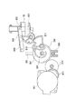
図6は、図5における磁気ヘッドユニット400付近を拡大した拡大斜視図であり、図7は、図6を底面から見た底面斜視図である。磁気ヘッドユニット400は略コの字の形状を有しており、向かい合う平行な一対の側面に磁気ヘッドガイド軸470、472が挿入されている。磁気ヘッドユニット400の上面には、上向きに磁気ヘッド410が一対の側面に挟まれて配されている。磁気ヘッドユニット400の底面には、基板432が取り付けられている。この基板432には、磁気ヘッド410により読み取られた情報をデジタル信号に変換するデコーダ430と、デコーダ430により変換されたデジタル信号をフレキシブルケーブル450へ出力するコネクタ460が取り付けられている。また、磁気ヘッドユニット400は底面において磁気ヘッド駆動ベルト480の一部を把持して固定している。   6 is an enlarged perspective view of the vicinity of the magnetic head unit 400 in FIG. 5, and FIG. 7 is a bottom perspective view of FIG. 6 viewed from the bottom. The magnetic head unit 400 has a substantially U-shape, and magnetic head guide shafts 470 and 472 are inserted into a pair of parallel sides facing each other. On the upper surface of the magnetic head unit 400, a magnetic head 410 is disposed so as to be sandwiched between a pair of side surfaces. A substrate 432 is attached to the bottom surface of the magnetic head unit 400. A decoder 430 that converts information read by the magnetic head 410 into a digital signal and a connector 460 that outputs the digital signal converted by the decoder 430 to the flexible cable 450 are attached to the substrate 432. The magnetic head unit 400 holds and fixes a part of the magnetic head driving belt 480 on the bottom surface.

デコーダ430は、磁気ヘッド410により読み取られた信号を数mVから数Vに増幅する増幅回路と、増幅された信号をデジタル信号に変換するA/D変換回路と、A/D変換されたデジタル信号を受け取って復調し、フレキシブルケーブル450に出力する復調回路とを有する。   The decoder 430 amplifies a signal read by the magnetic head 410 from several mV to several V, an A / D conversion circuit that converts the amplified signal into a digital signal, and an A / D converted digital signal And a demodulating circuit for demodulating and outputting to the flexible cable 450.

以上の構成により、磁気データ読取部40が被記録物100の底面に配された磁気ストライプ110の情報を読み取る場合に、まず、磁気ストライプ110が磁気ヘッド410の真上に来る読み取り位置に、搬送部30が被記録物100を搬送する。この状態において、磁気ヘッドモータ420が磁気ヘッド駆動ベルト480を回転駆動することにより、磁気ヘッドユニット400が、磁気ヘッド駆動ベルト480に引っ張られて、磁気ヘッドガイド軸470、472にガイドされつつ本体前部17の長手方向に往復移動する。これにより、磁気ヘッド410が磁気ストライプ110に下から当接して走査しつつ磁気ストライプ110からの情報を読み取る。この場合に、磁気ヘッドユニット400に配された基板432およびこの基板432に取り付けられたデコーダ430は磁気ヘッド410と共に往復移動し、磁気ヘッド410により読み取られた信号をデコーダ430の増幅回路が数mVから数Vに増幅し、増幅された信号をA/D変換回路がデジタル信号に変換し、このデジタル信号を復調回路が復調して、フレキシブルケーブル450に出力する。フレキシブルケーブル450は、弾性変形により湾曲して磁気ヘッドユニット400の往復移動に追従する。また、フレキシブルケーブル450は、デコーダ430からデジタル信号を受け取り、制御基板440へ伝送する。制御基板440に設けられた制御回路は、フレキシブルケーブル450からのデジタル信号に基づいて、磁気データ読取部40および記録部20を制御する。   With the above configuration, when the magnetic data reading unit 40 reads information on the magnetic stripe 110 disposed on the bottom surface of the recording material 100, first, the magnetic stripe 110 is transported to a reading position where the magnetic stripe 110 is directly above the magnetic head 410. The unit 30 conveys the recording material 100. In this state, the magnetic head motor 420 rotates and drives the magnetic head drive belt 480, whereby the magnetic head unit 400 is pulled by the magnetic head drive belt 480 and guided by the magnetic head guide shafts 470 and 472, while the front of the main body is being driven. It reciprocates in the longitudinal direction of the part 17. As a result, the magnetic head 410 reads information from the magnetic stripe 110 while scanning while contacting the magnetic stripe 110 from below. In this case, the substrate 432 disposed in the magnetic head unit 400 and the decoder 430 attached to the substrate 432 reciprocate together with the magnetic head 410, and the amplification circuit of the decoder 430 uses the amplification circuit of the decoder 430 to read several mV. The A / D converter circuit converts the amplified signal into a digital signal, and the demodulator circuit demodulates the digital signal and outputs it to the flexible cable 450. The flexible cable 450 is bent due to elastic deformation and follows the reciprocating movement of the magnetic head unit 400. The flexible cable 450 receives a digital signal from the decoder 430 and transmits the digital signal to the control board 440. A control circuit provided on the control board 440 controls the magnetic data reading unit 40 and the recording unit 20 based on a digital signal from the flexible cable 450.

記録部20により被記録物100に印字などの記録が行われた後に、その旨等を磁気データ読取部40が磁気ストライプ110に書き込む。この場合には、制御基板440からのアナログ信号をフレキシブルケーブル450が磁気ヘッド410へ伝送し、このアナログの信号に基づいて、磁気ヘッド410が磁気ストライプ110を走査しつつ、磁気ストライプ110に書き込みを行う。   After recording such as printing on the recording material 100 by the recording unit 20, the magnetic data reading unit 40 writes that fact on the magnetic stripe 110. In this case, the flexible cable 450 transmits an analog signal from the control board 440 to the magnetic head 410, and the magnetic head 410 scans the magnetic stripe 110 and writes to the magnetic stripe 110 based on the analog signal. Do.

以上により、磁気ヘッド410から読み取られた情報を、磁気ヘッド410の近傍に配されたデコーダ430がデジタル信号に変換してフレキシブルケーブル450に送信するので、フレキシブルケーブル450で送信される途中にノイズが乗っても、制御基板440上に配された制御回路が信号を誤読することを防ぐことができる。特に磁気ヘッドモータ420からノイズが発生しやすいが、磁気ヘッドモータ420の近傍を通るフレキシブルケーブル450が伝送するのはデジタル信号であるため、ノイズと信号との区別が容易であり、制御基板440における信号の誤読を抑えることができる。   As described above, the information read from the magnetic head 410 is converted into a digital signal by the decoder 430 disposed in the vicinity of the magnetic head 410 and transmitted to the flexible cable 450. Therefore, noise is transmitted while being transmitted by the flexible cable 450. Even if it gets on, it can prevent that the control circuit arranged on the control board 440 misreads the signal. In particular, noise is likely to be generated from the magnetic head motor 420, but since the flexible cable 450 passing through the vicinity of the magnetic head motor 420 transmits a digital signal, it is easy to distinguish the noise from the signal. Signal misreading can be suppressed.

なお、図5から図7に示す実施形態において、デコーダ430は、磁気ヘッドユニット400の底面に配された基板432に取り付けられている。しかしながら、デコーダ430が取り付けられる位置はこれに限られない。他の例として、磁気ヘッド410が、磁極412、コイル(不図示)、並びに、磁極412およびコイルを囲う磁気シールド416を有し、デコーダ430が磁気シールド416に囲われて磁気ヘッド410に組み込まれていてもよい。これにより、磁気ヘッド410とデコーダ430との間においてノイズが入りにくく、デコーダ430により変換されたデジタル信号が磁気ヘッド410から出力されるので、制御基板440に設けられた制御回路が信号を誤読することを防ぐことができる。   In the embodiment shown in FIGS. 5 to 7, the decoder 430 is attached to the substrate 432 disposed on the bottom surface of the magnetic head unit 400. However, the position where the decoder 430 is attached is not limited to this. As another example, the magnetic head 410 has a magnetic pole 412, a coil (not shown), and a magnetic shield 416 that surrounds the magnetic pole 412 and the coil, and the decoder 430 is surrounded by the magnetic shield 416 and incorporated in the magnetic head 410. It may be. As a result, noise hardly enters between the magnetic head 410 and the decoder 430, and the digital signal converted by the decoder 430 is output from the magnetic head 410. Therefore, the control circuit provided on the control board 440 misreads the signal. Can be prevented.

図8は、フロント加圧部300において、加圧ローラ側フレーム380の前面の一部を破断した斜視図である。フロント加圧部300は、上面が開放された略直方体の形状を有し、底面384に矩形の穴部386を有する加圧ローラ側フレーム380と、加圧ローラ側フレーム380に支持された加圧ローラユニット304と、加圧ローラユニット304を下方に付勢する付勢部340と、加圧ローラ側フレーム380の側面と平行な板状を有し、加圧ローラ側フレーム380に対して上下に移動可能に支持されたバネ側押し上げ部材354を備える。フロント加圧部300は、フロント加圧部300の下方に配されたフロント搬送部320の搬送ローラ324(図16に図示)との間で被記録物100を挟んで、被記録物100を搬送すべく、被記録物100を搬送ローラ324に加圧する。   FIG. 8 is a perspective view in which a part of the front surface of the pressure roller side frame 380 is broken in the front pressure unit 300. The front pressure unit 300 has a substantially rectangular parallelepiped shape with an open upper surface, a pressure roller side frame 380 having a rectangular hole 386 on the bottom surface 384, and a pressure supported by the pressure roller side frame 380. The roller unit 304, an urging portion 340 for urging the pressure roller unit 304 downward, and a plate shape parallel to the side surface of the pressure roller side frame 380, are arranged above and below the pressure roller side frame 380. A spring-side push-up member 354 that is movably supported is provided. The front pressure unit 300 conveys the recording material 100 with the recording material 100 sandwiched between the conveyance roller 324 (illustrated in FIG. 16) of the front conveyance unit 320 disposed below the front pressure unit 300. In order to achieve this, the recording material 100 is pressed against the conveying roller 324.

押圧力切替ユニット306は、加圧ローラ310の組、加圧ローラ310のそれぞれを連結する加圧ローラ軸312、加圧ローラ軸312を下方へ付勢する付勢部340、および、加圧ローラ310の組を外端で保持する自在継手370を有する。加圧ローラユニット304の加圧ローラ310は、穴部386から一部が底面384よりも下方に突出して、加圧ローラ側フレーム380に回転自在に保持されている。加圧ローラユニット304は、自在継手370によって連結された複数の加圧ローラ310の組を有する。図8に示す例において、加圧ローラユニット304は、2つの自在継手370によって連結された3つの加圧ローラ310の組を有する。さらに、加圧ローラ310の組は、それぞれ、2つの加圧ローラ310と、これら2つの加圧ローラを連結する加圧ローラ軸312を有する。これら2つの加圧ローラ310および加圧ローラ軸312は樹脂により一体に成形され、加圧ローラ310の平坦な外周にゴムが取り付けられる。これにより、加圧ローラ310を一つずつ自在継手370で連結する場合に比べ、自在継手370の数を減らして部品点数を少なくすることができるとともに、加圧ローラ310を回転駆動する負荷を小さくすることができる。   The pressing force switching unit 306 includes a pair of pressure rollers 310, a pressure roller shaft 312 that connects the pressure rollers 310, a biasing unit 340 that biases the pressure roller shaft 312 downward, and a pressure roller. It has a universal joint 370 that holds 310 sets at the outer end. A part of the pressure roller 310 of the pressure roller unit 304 protrudes below the bottom surface 384 from the hole 386 and is rotatably held by the pressure roller side frame 380. The pressure roller unit 304 has a set of a plurality of pressure rollers 310 connected by a universal joint 370. In the example shown in FIG. 8, the pressure roller unit 304 has a set of three pressure rollers 310 connected by two universal joints 370. Furthermore, each set of the pressure rollers 310 includes two pressure rollers 310 and a pressure roller shaft 312 that connects the two pressure rollers. The two pressure rollers 310 and the pressure roller shaft 312 are integrally formed of resin, and rubber is attached to the flat outer periphery of the pressure roller 310. As a result, the number of parts can be reduced by reducing the number of universal joints 370 and the load for rotationally driving the pressure roller 310 can be reduced as compared with the case where the pressure rollers 310 are connected one by one with the universal joint 370. can do.

図9は、図8の左側を拡大した拡大斜視図であり、図10は、図8の右側を拡大した拡大斜視図である。加圧ローラ側フレーム380は、U字の形状の軸支持部382を有する。加圧ローラ310の両端が軸支持部382に挿入されて、軸支持部382が加圧ローラユニット304を回転可能に軸支している。   9 is an enlarged perspective view in which the left side of FIG. 8 is enlarged, and FIG. 10 is an enlarged perspective view in which the right side of FIG. 8 is enlarged. The pressure roller side frame 380 includes a U-shaped shaft support portion 382. Both ends of the pressure roller 310 are inserted into the shaft support portion 382, and the shaft support portion 382 rotatably supports the pressure roller unit 304.

図9および図10に示すように、付勢部340は、加圧ローラ軸312を下方へ付勢する整列付勢用トーションバー342と、この整列付勢用トーションバー342よりも大きな力で加圧ローラ軸312を下方へ付勢する搬送用トーションバー344とを有する。本実施形態において、整列付勢用トーションバー342は金属製の針金であり、途中で略直角に折り曲げられている。整列付勢用トーションバー342の一端はバネ取り付け部346に取り付けられ、他端は加圧ローラ軸312に当接している。整列付勢用トーションバー342の折り曲げられている部分は、係止部347に係止されている。整列付勢用トーションバー342は軸まわりに捩られ、加圧ローラ軸312を下方へ付勢している。搬送用トーションバー344は、整列付勢用トーションバー342よりも径の大きい金属製の針金であり、途中で略直角に折り曲げられている。搬送用トーションバー344の一端はバネ取り付け部346に取り付けられ、他端は加圧ローラ軸312に当接している。搬送用トーションバー344の折り曲げられている部分は、係止部348に係止されている。搬送用トーションバー344は軸まわりに捩られ、加圧ローラ軸312を下方へ付勢している。   As shown in FIGS. 9 and 10, the urging unit 340 applies an alignment urging torsion bar 342 that urges the pressure roller shaft 312 downward, and a force larger than the alignment urging torsion bar 342. A torsion bar for conveyance 344 that urges the pressure roller shaft 312 downward. In the present embodiment, the alignment biasing torsion bar 342 is a metal wire and is bent at a substantially right angle in the middle. One end of the alignment biasing torsion bar 342 is attached to the spring attachment portion 346, and the other end is in contact with the pressure roller shaft 312. The bent portion of the alignment biasing torsion bar 342 is locked to the locking portion 347. The alignment biasing torsion bar 342 is twisted around the shaft and biases the pressure roller shaft 312 downward. The conveyance torsion bar 344 is a metal wire having a diameter larger than that of the alignment biasing torsion bar 342, and is bent at a substantially right angle on the way. One end of the conveying torsion bar 344 is attached to the spring attachment portion 346, and the other end is in contact with the pressure roller shaft 312. The bent portion of the conveying torsion bar 344 is locked to the locking portion 348. The conveying torsion bar 344 is twisted around the shaft and urges the pressure roller shaft 312 downward.

整列付勢用トーションバー342は、被記録物100を搬送方向に整列させるときを含み、加圧ローラ310を被記録物100へ押圧すべく、加圧ローラ軸312を下方に常時、付勢している。また、搬送用トーションバー344は、上記整列時においては図4に示す押し上げ機構350により押し上げられて加圧ローラ軸312を付勢しない一方、整列後の被記録物100を搬送するときに、加圧ローラ310を被記録物100に押圧すべく加圧ローラ軸312を下方に付勢する。加圧ローラ軸312は、一対の加圧ローラ310が配された略中央においてV字の溝314を有し、搬送用トーションバー344は、加圧ローラ軸312のV字の溝314において加圧ローラ軸312を付勢する。さらに、搬送用トーションバー344の一端は、バネ側押し上げ部材354に設けられた上下に長い溝355に挿入されている。なお、付勢部340は、本発明におけるローラ押圧装置の一例でもある。   The alignment urging torsion bar 342 includes a time when the recording material 100 is aligned in the transport direction, and always urges the pressure roller shaft 312 downward to press the pressure roller 310 against the recording material 100. ing. Further, the conveying torsion bar 344 is pushed up by the push-up mechanism 350 shown in FIG. 4 during the alignment and does not urge the pressure roller shaft 312, while the conveying torsion bar 344 is added when conveying the aligned recording material 100. In order to press the pressure roller 310 against the recording material 100, the pressure roller shaft 312 is urged downward. The pressure roller shaft 312 has a V-shaped groove 314 at substantially the center where the pair of pressure rollers 310 are arranged, and the conveying torsion bar 344 is pressed in the V-shaped groove 314 of the pressure roller shaft 312. The roller shaft 312 is urged. Further, one end of the conveying torsion bar 344 is inserted into a vertically long groove 355 provided in the spring-side push-up member 354. The urging unit 340 is also an example of a roller pressing device in the present invention.

これにより、整列付勢用トーションバー342および搬送用トーションバー344が加圧ローラユニット304を被記録物100へ、強弱の2段階で押しつけるので、2つのコイルバネおよびコイルバネにより付勢されるスリーブを用いる場合に比べて、加圧ローラユニット304を押圧する機構を小さくすることができる。   As a result, the alignment biasing torsion bar 342 and the conveying torsion bar 344 press the pressure roller unit 304 against the recording material 100 in two steps of strength and weakness, so two coil springs and a sleeve biased by the coil springs are used. Compared to the case, the mechanism for pressing the pressure roller unit 304 can be made smaller.

また、整列付勢用トーションバー342および搬送用トーションバー344は、一対の加圧ローラ310を有する組のそれぞれにおいて、一対の加圧ローラ310を連結している加圧ローラ軸312を付勢している。これにより、一組の加圧ローラ310における各加圧ローラ310を整列付勢用トーションバー342および搬送用トーションバー344が均等に付勢することができる。   Further, the alignment biasing torsion bar 342 and the conveying torsion bar 344 bias the pressure roller shaft 312 connecting the pair of pressure rollers 310 in each pair including the pair of pressure rollers 310. ing. As a result, the alignment biasing torsion bar 342 and the conveying torsion bar 344 can equally bias each pressure roller 310 in the set of pressure rollers 310.

なお、図10に示すように、加圧ローラユニット304の右端には加圧側伝達歯車311が連結され、フロント搬送部320からの駆動力を伝達して加圧ローラ310を回転駆動する。加圧ローラユニット304がU字の形状の軸支持部382に軸支されていることより、加圧側伝達歯車311が加圧ローラユニット304を一体的に回転駆動することができる。   As shown in FIG. 10, a pressure-side transmission gear 311 is connected to the right end of the pressure roller unit 304 to transmit the driving force from the front transport unit 320 to rotationally drive the pressure roller 310. Since the pressure roller unit 304 is pivotally supported by the U-shaped shaft support portion 382, the pressure-side transmission gear 311 can rotate and drive the pressure roller unit 304 integrally.

図11は、記録装置10に挿入された被記録物100を、記録装置10が、プラテン部50の手前まで搬送し、その後に整列し、整列後にさらにプラテン部50上へ搬送する動作を示すタイミングチャートである。   FIG. 11 is a timing diagram illustrating an operation in which the recording object 10 inserted into the recording apparatus 10 is transported to the front of the platen unit 50, aligned thereafter, and further transported onto the platen unit 50 after alignment. It is a chart.

図11に示すように、被記録物100が記録装置10に挿入される前の待機状態において、加圧ローラ310および搬送ローラ324は停止している。この待機状態において、整列板360、および、後述する押し上げ機構350の押し上げ部材351は、共に上方の位置にあり、搬送用トーションバー344は加圧ローラ軸312を付勢していない。一方、整列付勢用トーションバー342は、加圧ローラ軸312を付勢している。   As shown in FIG. 11, the pressure roller 310 and the conveyance roller 324 are stopped in a standby state before the recording object 100 is inserted into the recording apparatus 10. In this standby state, the alignment plate 360 and the push-up member 351 of the push-up mechanism 350 described later are both in the upper position, and the conveying torsion bar 344 does not urge the pressure roller shaft 312. On the other hand, the alignment biasing torsion bar 342 biases the pressure roller shaft 312.

上記待機状態から記録装置10へ被記録物100が挿入されると、加圧ローラ310および搬送ローラ324が回転し、被記録物100を挟んで整列板360に当接するまで搬送する。この場合に、被記録物100が搬送方向に対して傾いている場合には、被記録物100の一部が先に整列板360に当接し、その時に他の部分はまだ整列板360に当接していない。この状態において、さらに加圧ローラ310および搬送ローラ324が回転すると、被記録物100においてまだ整列板360に当接していない部分は、この部分の近傍に配された加圧ローラ310および搬送ローラ324により整列板360に当接するまで搬送されつつ、先に整列板360に当接している部分は、それ以上搬送されない。この場合に、加圧ローラ310は弱い付勢力を有する整列付勢用トーションバー342により被記録物100へ付勢されているので、被記録物100において先に整列板360に当接している部分の近傍に配された加圧ローラ310および搬送ローラ324は、被記録物100上を空回りする。整列板360の近傍に配された光学センサ(不図示)により、被記録物100が整列されたと判断されると、加圧ローラ310および搬送ローラ324の回転が停止する。   When the recording material 100 is inserted into the recording apparatus 10 from the standby state, the pressure roller 310 and the conveying roller 324 rotate and convey the recording material 100 until the recording material 100 is in contact with the alignment plate 360. In this case, when the recording object 100 is inclined with respect to the transport direction, a part of the recording object 100 comes into contact with the alignment plate 360 first, and at this time, the other part still contacts the alignment plate 360. Not touching. In this state, when the pressure roller 310 and the conveyance roller 324 are further rotated, the portion of the recording medium 100 that is not yet in contact with the alignment plate 360 has the pressure roller 310 and the conveyance roller 324 arranged in the vicinity of this portion. Thus, the portion that is in contact with the alignment plate 360 first is not conveyed any more while being conveyed until the contact with the alignment plate 360. In this case, since the pressure roller 310 is urged to the recording material 100 by the alignment urging torsion bar 342 having a weak urging force, a portion of the recording material 100 that is in contact with the alignment plate 360 first. The pressure roller 310 and the conveyance roller 324 arranged in the vicinity of the head idle around the recording material 100. When the optical sensor (not shown) arranged in the vicinity of the alignment plate 360 determines that the recording objects 100 are aligned, the rotation of the pressure roller 310 and the conveyance roller 324 is stopped.

被記録物100が整列した後に、押し上げ部材351が下降する。これにより、押し上げ部材351は、押し上げていた搬送用トーションバー344を加圧ローラ軸312のV字の溝314に当接させる。次に、押し上げ部材351が所定位置まで下降した後にさらに下降するのと連動して、整列板360も下降する。整列板360が被記録物100の搬送経路から退避した位置まで下降するとその位置で停止し、これに合わせて押し上げ部材351も下降を停止する。   After the recording objects 100 are aligned, the push-up member 351 is lowered. Accordingly, the push-up member 351 brings the pushed-up conveyance torsion bar 344 into contact with the V-shaped groove 314 of the pressure roller shaft 312. Next, in conjunction with the further lowering of the push-up member 351 after being lowered to a predetermined position, the alignment plate 360 is also lowered. When the alignment plate 360 is lowered to the position retracted from the conveyance path of the recording material 100, the alignment plate 360 stops at that position, and the push-up member 351 also stops descending accordingly.

整列板360および押し上げ部材351が停止した後に、加圧ローラ310および搬送ローラ324が再び回転し、被記録物100を挟んでプラテン部50上まで搬送し、記録部20が記録を行う。この場合に、加圧ローラ310は、加圧ローラ軸312を介して整列付勢用トーションバー342および搬送用トーションバー344により強い付勢力で被記録物100へ押圧されているので、加圧ローラ310および搬送ローラ324は被記録物100を確実に挟んで搬送することができる。   After the alignment plate 360 and the push-up member 351 are stopped, the pressure roller 310 and the conveyance roller 324 are rotated again and conveyed onto the platen unit 50 with the recording material 100 interposed therebetween, and the recording unit 20 performs recording. In this case, the pressure roller 310 is pressed against the recording material 100 with a strong biasing force by the alignment biasing torsion bar 342 and the conveying torsion bar 344 via the pressure roller shaft 312. 310 and the conveyance roller 324 can convey the recording material 100 with certainty.

図12は、押し上げ機構350の部分断面図である。図12において、整列板360が被記録物100の搬送経路から退避し、かつ、搬送用トーションバー344が加圧ローラ軸312を付勢している状態が示されている。   FIG. 12 is a partial cross-sectional view of the push-up mechanism 350. FIG. 12 shows a state in which the alignment plate 360 is retracted from the conveyance path of the recording material 100 and the conveyance torsion bar 344 urges the pressure roller shaft 312.

図12に示すように、押し上げ機構350は、溝355が設けられ、この溝355に搬送用トーションバー344が挿入されているバネ側押し上げ部材354、このバネ側押し上げ部材354の下面に当接するフォロワー側押し上げ部材352、フォロワー側押し上げ部材352と一体の上下方向に延伸した板状のフォロワー部材368、および、カム軸394まわりに回転可能に本体部11に支持され、フォロワー部材368をフォロワーとして上下に往復移動させる第1カム390を有する。これらバネ側押し上げ部材354およびフォロワー側押し上げ部材352が押し上げ部材351を構成している。   As shown in FIG. 12, the push-up mechanism 350 is provided with a groove 355, and a spring-side push-up member 354 in which a conveying torsion bar 344 is inserted in the groove 355, and a follower that contacts the lower surface of the spring-side push-up member 354. A side-up member 352, a plate-like follower member 368 extending in the up-and-down direction integrally with the follower-side push-up member 352, and supported by the main body 11 so as to be rotatable around the cam shaft 394, and the follower member 368 as a follower up and down. A first cam 390 that reciprocates is provided. The spring-side push-up member 354 and the follower-side push-up member 352 constitute a push-up member 351.

フォロワー部材368は、上述のように上部でフォロワー側押し上げ部材352と一体となっている。さらにフォロワー部材368の上部には、コイルバネ362を介して整列板360が配されている。フォロワー部材368の上下方向の略中央には、上下方向に長い長孔364が設けられ、この長孔364には、第1カム390のカム軸394が挿入されている。さらに、フォロワー部材368の下部には、下方に開口した切り欠き366が設けられ、この切り欠き366には、本体部11に固定されたフォロワー固定軸396が挿入されている。フォロワー部材368におけるこれら長孔364と切り欠き366との間には、カムフォロアピン398が貫通して取り付けられている。   The follower member 368 is integrated with the follower side push-up member 352 at the upper portion as described above. Further, an alignment plate 360 is disposed on the follower member 368 via a coil spring 362. A long hole 364 that is long in the vertical direction is provided at a substantially center in the vertical direction of the follower member 368, and the cam shaft 394 of the first cam 390 is inserted into the long hole 364. Further, a notch 366 that opens downward is provided in the lower portion of the follower member 368, and a follower fixing shaft 396 that is fixed to the main body 11 is inserted into the notch 366. A cam follower pin 398 is attached so as to penetrate between the elongated hole 364 and the notch 366 in the follower member 368.

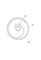
第1カム390は、略円板の形状を有し、フォロワー部材368と対向する側面において、渦巻き形状のカム溝392を有する。カム溝392には、フォロワー部材368に貫通して取り付けられたカムフォロアピン398の一端が挿入されている。   The first cam 390 has a substantially disc shape, and has a spiral cam groove 392 on the side surface facing the follower member 368. One end of a cam follower pin 398 inserted through the follower member 368 is inserted into the cam groove 392.

図12に示す状態において、カムフォロアピン398は渦巻き形状のカム溝392においてカム軸394から離れた下方の位置にある。これにより、フォロワー部材368は、カム軸394が支持されている本体部11に対して、可動範囲の最下位置にある。フォロワー部材368が最下位置にある場合に、整列板360の上部に配された整列板360は、被記録物100の搬送経路よりも下方にあって搬送経路から退避している。同様に、フォロワー部材368の上部に連結されているフォロワー側押し上げ部材352も最下位置にあり、フォロワー側押し上げ部材352と当接しているバネ側押し上げ部材354は、搬送用トーションバー344が加圧ローラ軸312を付勢することを許容している。   In the state shown in FIG. 12, the cam follower pin 398 is at a lower position away from the cam shaft 394 in the spiral cam groove 392. Thus, the follower member 368 is at the lowest position in the movable range with respect to the main body 11 on which the cam shaft 394 is supported. When the follower member 368 is at the lowest position, the alignment plate 360 disposed above the alignment plate 360 is below the conveyance path of the recording material 100 and is retracted from the conveyance path. Similarly, the follower-side push-up member 352 connected to the upper portion of the follower member 368 is also at the lowest position, and the spring-side push-up member 354 in contact with the follower-side push-up member 352 is pressurized by the torsion bar 344 for conveyance. The roller shaft 312 is allowed to be biased.

この状態から、待機状態にするには、図示しない駆動手段により、第1カム390が図12における実線の矢印の方向に回転駆動される。第1カム390が矢印の方向に回転すると、カムフォロアピン398がカム溝392に沿って第1カム390に対して上昇する。この場合に、カム軸394およびフォロワー固定軸396が長孔364および切り欠き366に挿入されているので、第1カム390が矢印の方向に回転した場合に、フォロワー部材368が左右にぶれることなく本体部11に対して上昇することができる。   In order to change from this state to the standby state, the first cam 390 is rotationally driven in the direction of the solid arrow in FIG. When the first cam 390 rotates in the direction of the arrow, the cam follower pin 398 rises with respect to the first cam 390 along the cam groove 392. In this case, since the cam shaft 394 and the follower fixing shaft 396 are inserted into the long hole 364 and the notch 366, the follower member 368 does not sway left and right when the first cam 390 rotates in the direction of the arrow. The main body 11 can be raised.

図13は、整列板360が被記録物100の搬送経路に進出し、かつ、搬送用トーションバー344が加圧ローラ軸312から離れている状態を示す部分断面図である。図12に示す状態から、第1カム390が回転することによりフォロワー部材368が上昇すると、ついには、図13に示すように整列板360の上端が加圧ローラ側フレーム380の底面384に当接する。これにより、整列板360は被記録物100の搬送経路に進出する。   FIG. 13 is a partial cross-sectional view showing a state in which the alignment plate 360 has advanced into the conveyance path of the recording material 100 and the conveyance torsion bar 344 is separated from the pressure roller shaft 312. When the follower member 368 is lifted by the rotation of the first cam 390 from the state shown in FIG. . As a result, the alignment plate 360 advances into the conveyance path of the recording material 100.

この状態からさらに第1カム390が回転すると、整列板360は底面384と当接しているのでこれ以上は上昇しないが、整列板360とフォロワー部材368との間にはコイルバネ362が配されているため、コイルバネ362の付勢力に抗しつつ、フォロワー部材368はさらに上昇する。これに伴い、フォロワー部材368の上部に連結しているフォロワー側押し上げ部材352も上昇し、フォロワー側押し上げ部材352に当接しているバネ側押し上げ部材354を押し上げる。これにより、バネ側押し上げ部材354は、溝355に挿入されている搬送用トーションバー344の一端を押し上げ、搬送用トーションバー344を加圧ローラ軸312の上方に移動して、加圧ローラ軸312への付勢力を解除する。これにより、被記録物100が搬送方向について整列される場合には搬送用トーションバー344の付勢を加圧ローラ軸312から解除することができる。この状態が図11に示す待機状態であり、記録装置10へ被記録物100が挿入されると、被記録物100を加圧ローラ310および搬送ローラ324が挟んで回転し、被記録物100を整列板360に当接し整列するまで搬送する。   When the first cam 390 further rotates from this state, the alignment plate 360 is in contact with the bottom surface 384 and thus does not rise any further, but a coil spring 362 is disposed between the alignment plate 360 and the follower member 368. Therefore, the follower member 368 further moves up against the urging force of the coil spring 362. Along with this, the follower-side push-up member 352 connected to the upper part of the follower member 368 is also raised, and the spring-side push-up member 354 that is in contact with the follower-side push-up member 352 is pushed up. As a result, the spring-side push-up member 354 pushes up one end of the conveying torsion bar 344 inserted in the groove 355, moves the conveying torsion bar 344 above the pressure roller shaft 312, and pressurizes the pressure roller shaft 312. Release the biasing force. Thus, when the recording materials 100 are aligned in the transport direction, the urging of the transport torsion bar 344 can be released from the pressure roller shaft 312. This state is the standby state shown in FIG. 11, and when the recording material 100 is inserted into the recording apparatus 10, the recording material 100 is rotated with the pressure roller 310 and the conveying roller 324 interposed therebetween, and the recording material 100 is rotated. The sheet is conveyed until it contacts the alignment plate 360 and is aligned.

図13に示す状態において被記録物100の整列が終了した場合に、上述の駆動手段により、第1カム390が図13に示す破線の矢印の方向に回転駆動される。第1カム390が矢印の方向に回転すると、カムフォロアピン398がカム溝392に沿って第1カム390に対して下降する。これにより、フォロワー部材368が本体部11に対して下降する。この場合に、まず、整列板360と一体となっているフォロワー側押し上げ部材352が下降するので、フォロワー側押し上げ部材352と当接しているバネ側押し上げ部材354も下降する。バネ側押し上げ部材354が押し上げていた搬送用トーションバー344の一端が下方に下がり、搬送用トーションバー344は、加圧ローラ軸312の溝314に再び挿入されて、加圧ローラ軸312を下方に付勢する。図9および図10に示すように、搬送用トーションバー344は加圧ローラ軸312に配されたV字の溝314において加圧ローラ軸312を付勢するので、加圧ローラ軸312から一旦、上昇して離脱しても、加圧ローラ軸312を毎回略同じ位置で付勢することができる。さらに、加圧ローラ310を回転駆動する場合であっても、加圧ローラ310を回転駆動しつつ、回転軸と直交する方向に加圧ローラ軸312を付勢することができる。   When the alignment of the recording objects 100 is completed in the state shown in FIG. 13, the first cam 390 is driven to rotate in the direction of the broken arrow shown in FIG. When the first cam 390 rotates in the direction of the arrow, the cam follower pin 398 descends with respect to the first cam 390 along the cam groove 392. As a result, the follower member 368 descends with respect to the main body 11. In this case, first, the follower-side push-up member 352 integrated with the alignment plate 360 is lowered, so that the spring-side push-up member 354 that is in contact with the follower-side push-up member 352 is also lowered. One end of the conveying torsion bar 344 pushed up by the spring-side push-up member 354 is lowered downward, and the conveying torsion bar 344 is reinserted into the groove 314 of the pressure roller shaft 312 to move the pressure roller shaft 312 downward. Energize. As shown in FIGS. 9 and 10, the conveying torsion bar 344 urges the pressure roller shaft 312 in the V-shaped groove 314 disposed on the pressure roller shaft 312, and therefore, once from the pressure roller shaft 312, Even if it is lifted and separated, the pressure roller shaft 312 can be urged at substantially the same position every time. Further, even when the pressure roller 310 is rotationally driven, the pressure roller shaft 312 can be urged in a direction orthogonal to the rotational axis while the pressure roller 310 is rotationally driven.

さらに、第1カム390が破線の矢印の方向に回転することにより、フォロワー部材368がさらに下降すると、これに伴い、整列板360も下降して被記録物100の搬送経路から退避し、図12に示す状態へ戻る。   Further, when the follower member 368 is further lowered due to the rotation of the first cam 390 in the direction of the broken line arrow, the alignment plate 360 is also lowered and retracted from the conveyance path of the recording material 100, and FIG. Return to the state shown in.

図14および図15は、リア加圧部302を回転軸に垂直な平面で切断した断面図である。図14は、溝314を通る平面で切断し、図15は、リアフレーム330の軸支持部332を通る平面で切断している。なお、図14および図15に示すリア加圧部302の加圧ローラユニットは、フロント加圧部300の加圧ローラユニット304と同一の構成を有するため、加圧ローラユニット304と同一の符号を用いて説明する。   14 and 15 are cross-sectional views of the rear pressure unit 302 taken along a plane perpendicular to the rotation axis. FIG. 14 is cut along a plane passing through the groove 314, and FIG. 15 is cut along a plane passing through the shaft support portion 332 of the rear frame 330. The pressure roller unit of the rear pressure unit 302 shown in FIGS. 14 and 15 has the same configuration as the pressure roller unit 304 of the front pressure unit 300, and therefore, the same reference numerals as those of the pressure roller unit 304 are used. It explains using.

図14および図15に示すように、リア加圧部302は、加圧ローラユニット304と、加圧ローラユニット304を回転自在に軸支するリアフレーム330と、加圧ローラユニット304を被記録物100へ向けて下方に付勢する付勢部334とを有する。リアフレーム330には、U字の形状を有する軸支持部332が設けられている。この軸支持部332には、加圧ローラ軸312が挿入されて加圧ローラ軸312が回転可能に支持されている。加圧ローラユニット304が軸支持部332に軸支されていることより、加圧ローラユニット304を一体的に回転駆動させることができる。   As shown in FIGS. 14 and 15, the rear pressure unit 302 includes a pressure roller unit 304, a rear frame 330 that rotatably supports the pressure roller unit 304, and the pressure roller unit 304 to be recorded. And a biasing portion 334 that biases downward toward 100. The rear frame 330 is provided with a shaft support portion 332 having a U-shape. A pressure roller shaft 312 is inserted into the shaft support portion 332, and the pressure roller shaft 312 is rotatably supported. Since the pressure roller unit 304 is pivotally supported by the shaft support portion 332, the pressure roller unit 304 can be integrally rotated.

付勢部334は、金属製の針金であり、V字の溝314において加圧ローラユニット304を常時、被記録物100へ向けて下方に付勢している。加圧ローラ軸312は樹脂により形成されており、付勢部334は金属により形成されているので、加圧ローラ軸312が回転していても、加圧ローラ軸312に対して付勢部334が摺動することにより、付勢部334が加圧ローラ軸312を回転軸と直交する方向に、より確実に付勢することができる。よって、コイルバネおよびコイルバネにより付勢されるスリーブを用いて各々の加圧ローラ310の両側の加圧ローラ軸312を押圧する場合に比べて、加圧ローラユニット304を押圧する機構を小さくすることができる。   The urging unit 334 is a metal wire, and always urges the pressure roller unit 304 downward toward the recording material 100 in the V-shaped groove 314. Since the pressure roller shaft 312 is made of resin and the urging portion 334 is made of metal, the urging portion 334 with respect to the pressure roller shaft 312 is rotated even if the pressure roller shaft 312 is rotating. By sliding, the urging portion 334 can urge the pressure roller shaft 312 more reliably in the direction orthogonal to the rotation axis. Therefore, the mechanism for pressing the pressure roller unit 304 can be made smaller than when the pressure roller shafts 312 on both sides of each pressure roller 310 are pressed using a coil spring and a sleeve biased by the coil spring. it can.

図16は、フロント加圧部300およびフロント搬送部320が被記録物100を挟んで搬送する動作を示す部分背面図である。なお、リア加圧部302およびリア搬送部322が被記録物100を搬送する場合も同様の動作をするので、それらについては説明を省略する。   FIG. 16 is a partial rear view illustrating an operation in which the front pressurizing unit 300 and the front transport unit 320 transport the recording material 100 with the recording material 100 interposed therebetween. Note that the same operation is performed when the rear pressurizing unit 302 and the rear transport unit 322 transport the recording material 100, and thus the description thereof is omitted.

図16に示すように、被記録物100が加圧ローラユニット304とフロント搬送部320との間に配されると、加圧ローラユニット304において被記録物100の幅に応じた加圧ローラ310が、被記録物100上に乗り上げる。この状態において、加圧ローラ軸312が回転駆動されることにより、搬送側伝達歯車321および加圧側伝達歯車311を介して、加圧ローラユニット304が回転駆動される。これにより、被記録物100が想定される最も狭い幅または最も広い幅のみならず、いずれの幅を有している場合であっても、加圧ローラ310が被記録物100に乗り上げて、加圧ローラユニット304全体が被記録物100に対して傾くことなく、フロント搬送部320との間で被記録物100を挟み、被記録物100を正確に搬送することができる。特に一対の加圧ローラ310において、加圧ローラ310の一方が乗り上げても、両方の加圧ローラ310を付勢部340が均等に付勢することができる。また、加圧ローラユニット304における自在継手370は直接付勢されておらず半径方向の力が加わらないので、加圧ローラユニット304に駆動力を与えて回転させる場合に、加圧ローラユニット304はがたつかずに円滑に回転し、被記録物100の振動を抑えて記録の精度を向上させることができる。   As shown in FIG. 16, when the recording material 100 is disposed between the pressure roller unit 304 and the front conveyance unit 320, the pressure roller 310 according to the width of the recording material 100 in the pressure roller unit 304. However, it rides on the recording object 100. In this state, when the pressure roller shaft 312 is rotationally driven, the pressure roller unit 304 is rotationally driven via the conveyance side transmission gear 321 and the pressure side transmission gear 311. As a result, not only the narrowest or widest width of the recording material 100 that is assumed, but also the width of the recording material 100, the pressure roller 310 rides on the recording material 100 and is added. Without being inclined with respect to the recording material 100 as a whole, the recording material 100 can be sandwiched between the front conveyance unit 320 and the recording material 100 can be accurately conveyed. In particular, in the pair of pressure rollers 310, even if one of the pressure rollers 310 rides on, the urging unit 340 can urge both pressure rollers 310 evenly. Further, since the universal joint 370 in the pressure roller unit 304 is not directly urged and no radial force is applied, the pressure roller unit 304 is rotated when a driving force is applied to the pressure roller unit 304 to rotate it. It can rotate smoothly without rattling and suppress the vibration of the recording material 100 to improve the recording accuracy.

図17は、図4におけるプラテン部50付近を拡大した拡大断面図であり、図18は、図17をXで示す水平面で切断して上から見た断面図である。なお、図17の切断面は、図4の切断面よりも奥側(図18における左側)である。   FIG. 17 is an enlarged cross-sectional view in which the vicinity of the platen portion 50 in FIG. 4 is enlarged, and FIG. 18 is a cross-sectional view as seen from above by cutting FIG. In addition, the cut surface of FIG. 17 is a back | inner side (left side in FIG. 18) rather than the cut surface of FIG.

図17および図18に示すように、プラテン部50は、記録ヘッド200の下方に配されたプラテン500と、プラテン500を下方から押し上げて支持する支持バネ550と、記録ヘッド200が往復移動する方向において支持バネ550と同じ位置に設けられ、プラテン500の高さの上限を規制するプラテン高さ規制部560と、プラテン500の上下方向の移動を案内するプラテン案内部材532、534と、プラテン500の下方に配された振動吸収部材540とを備える。記録ヘッド200には、記録ヘッド200に対して回動自在にギャップ保持部220としてのコロが取り付けられている。   As shown in FIGS. 17 and 18, the platen unit 50 includes a platen 500 disposed below the recording head 200, a support spring 550 that pushes up and supports the platen 500 from below, and a direction in which the recording head 200 reciprocates. , The platen height restricting portion 560 for restricting the upper limit of the height of the platen 500, platen guide members 532 and 534 for guiding the vertical movement of the platen 500, and the platen 500 And a vibration absorbing member 540 disposed below. A roller as a gap holding unit 220 is attached to the recording head 200 so as to be rotatable with respect to the recording head 200.

プラテン500は、記録ヘッド200の移動方向に延伸する板状のプラテン本体510と、プラテン本体510の下方において被記録物100の搬送方向の下流側に延伸する一対のプラテン足部520とを備える。プラテン本体510およびプラテン足部520は、例えば弾性を有する樹脂を射出成形することにより一体に形成される。プラテン本体510における記録ヘッド200の移動方向の両端には、さらに記録ヘッド200の移動方向について外側に突出するピン515、516が設けられている。   The platen 500 includes a plate-like platen main body 510 that extends in the moving direction of the recording head 200, and a pair of platen legs 520 that extend below the platen main body 510 in the conveyance direction of the recording material 100. The platen main body 510 and the platen foot 520 are integrally formed by, for example, injection molding a resin having elasticity. At both ends of the platen main body 510 in the moving direction of the recording head 200, pins 515 and 516 that protrude outward in the moving direction of the recording head 200 are provided.

プラテン本体510は、記録ヘッド200と対向する上面が平坦な上部512、および、上部512よりも被記録物100の搬送方向の幅が狭い下部514を有する。これにより、プラテン本体510の断面は、図17に示すように傘状の形状を有する。上部512の上面およびこの上面に搬送された被記録物100の上をギャップ保持部220が転がりながら、上部512の長手方向にギャップ保持部220および記録ヘッド200が移動する。この場合に、ギャップ保持部220は、上部512の上面を直接または被記録物100を介して押し下げることにより、被記録物100と記録ヘッド200とのギャップを保持する。プラテン足部520は、後述するプラテン高さ規制部560に当接することにより、支持バネ550に押し上げられているプラテン500の高さの上限を規制している。   The platen main body 510 has an upper portion 512 having a flat upper surface facing the recording head 200 and a lower portion 514 having a width in the transport direction of the recording material 100 narrower than the upper portion 512. Thereby, the cross section of the platen main body 510 has an umbrella shape as shown in FIG. The gap holder 220 and the recording head 200 move in the longitudinal direction of the upper portion 512 while the gap holder 220 rolls on the upper surface of the upper portion 512 and the recording material 100 conveyed to the upper surface. In this case, the gap holding unit 220 holds the gap between the recording object 100 and the recording head 200 by pushing down the upper surface of the upper part 512 directly or via the recording object 100. The platen foot part 520 restricts the upper limit of the height of the platen 500 pushed up by the support spring 550 by contacting a platen height restricting part 560 described later.

プラテン案内部材532、534は、プラテン500における記録ヘッド200が往復移動する方向の両端に配され、本体部11から鉛直上方に立ち上がっている。これらプラテン案内部材532、534は、それぞれ鉛直方向に案内溝部533、535を有する。案内溝部533にプラテン500のピン515が挿入されると共に、案内溝部535にプラテン500のピン516が挿入されることにより、案内溝部533、535は、プラテン500の上下の移動を案内する。さらに、案内溝部533、535の底面とピン515、516が当接することにより、プラテン500の高さの下限が規制される。ただし、記録に用いられることが想定される最も厚い被記録物100を介してプラテン500が押し下げられた場合にも、ピン515,516が案内溝部533、535の底面に当接しないように底面の高さが設定されている。   The platen guide members 532 and 534 are arranged at both ends of the platen 500 in the direction in which the recording head 200 reciprocates and rises vertically upward from the main body 11. These platen guide members 532 and 534 have guide groove portions 533 and 535 in the vertical direction, respectively. When the pin 515 of the platen 500 is inserted into the guide groove 533 and the pin 516 of the platen 500 is inserted into the guide groove 535, the guide grooves 533 and 535 guide the vertical movement of the platen 500. Furthermore, the lower limit of the height of the platen 500 is regulated by the bottom surfaces of the guide groove portions 533 and 535 coming into contact with the pins 515 and 516. However, even when the platen 500 is pushed down through the thickest recording material 100 that is supposed to be used for recording, the pins 515 and 516 do not contact the bottom surfaces of the guide groove portions 533 and 535. The height is set.

振動吸収部材540は、例えば、スポンジなど吸音性および弾性を有する材料により形成され、プラテン500の下部514の下方および側面の一部を覆うように、被記録物100の搬送方向について整列板360とリア搬送部322との間に配されている。振動吸収部材540は、プラテン500のプラテン足部520に密着して、これを被記録物100の搬送方向の両側から挟みこむ。さらに、振動吸収部材540は、プラテン500をプラテン案内部材532、534に付勢する。図17および図18に示す実施形態において、振動吸収部材540における被記録物100の搬送方向の上流側が、搬送方向に沿った方向に、下流側よりも大きく押しつぶされた状態で、プラテン500の下部514が挿入される。これにより、振動吸収部材540において、プラテン500の下部514に対する搬送方向の上流側からの付勢力が、下流側からの付勢力よりも強くなる。よって、プラテン500は全体として下流側に付勢され、プラテン500のピン515、516がそれぞれ案内溝部533、535における被記録物100の下流側の側壁に押しつけられる。これにより、プラテン500が振動する上下方向に直交する方向に、振動吸収部材540が、プラテン500を付勢して、プラテン500の振動をより確実に吸収することができる。   The vibration absorbing member 540 is made of, for example, a material having sound absorption and elasticity, such as sponge, and is arranged with the alignment plate 360 in the conveyance direction of the recording material 100 so as to cover the lower portion 514 of the platen 500 and a part of the side surface. It is arranged between the rear conveyance unit 322. The vibration absorbing member 540 is in close contact with the platen leg 520 of the platen 500 and sandwiches it from both sides of the recording material 100 in the transport direction. Further, the vibration absorbing member 540 biases the platen 500 to the platen guide members 532 and 534. In the embodiment shown in FIGS. 17 and 18, the upper side of the vibration absorbing member 540 in the transport direction of the recording material 100 is crushed in the direction along the transport direction to a greater extent than the downstream side, and the lower part of the platen 500. 514 is inserted. Thereby, in the vibration absorbing member 540, the urging force from the upstream side in the transport direction with respect to the lower portion 514 of the platen 500 becomes stronger than the urging force from the downstream side. Accordingly, the platen 500 is urged downstream as a whole, and the pins 515 and 516 of the platen 500 are pressed against the downstream side walls of the recording material 100 in the guide groove portions 533 and 535, respectively. As a result, the vibration absorbing member 540 urges the platen 500 in a direction perpendicular to the vertical direction in which the platen 500 vibrates, so that the vibration of the platen 500 can be more reliably absorbed.

ここで、プラテン500の上部512の下面513と振動吸収部材540の上面542との間に、プラテン500が上下方向に移動する移動幅よりも小さい間隙Gが設けられている。これにより、プラテン500の上下の移動量が小さいときには、プラテン500が振動する方向に直交する方向の付勢力により振動吸収部材540が振動を吸収する。さらに、プラテン500の上下の移動量が大きいときには、振動吸収部材540がプラテン500の上部512に当接して、上下方向についてもプラテン500の振動を吸収する。よって、記録ヘッド200の押下に対してプラテン500が追従しつつ、その後のプラテン500の振動を振動吸収部材540がより確実に吸収することができる。   Here, a gap G smaller than the moving width in which the platen 500 moves in the vertical direction is provided between the lower surface 513 of the upper portion 512 of the platen 500 and the upper surface 542 of the vibration absorbing member 540. As a result, when the amount of vertical movement of the platen 500 is small, the vibration absorbing member 540 absorbs vibration by the biasing force in the direction orthogonal to the direction in which the platen 500 vibrates. Further, when the amount of vertical movement of the platen 500 is large, the vibration absorbing member 540 comes into contact with the upper portion 512 of the platen 500 and absorbs vibration of the platen 500 also in the vertical direction. Therefore, the vibration absorbing member 540 can more reliably absorb the vibration of the subsequent platen 500 while the platen 500 follows the pressing of the recording head 200.

図19および図20は、ギャップ保持部220により押し下げられた場合にプラテン500が湾曲する状態を説明する概略図である。なお図19は、記録ヘッド200が待機位置に近い位置にある状態を示し、図20は、記録ヘッド200が往復移動の略中心に位置する状態を示す。なお、図中の矢印は、プラテン500においてプラテン高さ規制部560により高さが制限されている位置を示す。   FIGS. 19 and 20 are schematic diagrams for explaining a state in which the platen 500 bends when pushed down by the gap holding unit 220. FIG. 19 shows a state where the recording head 200 is in a position close to the standby position, and FIG. 20 shows a state where the recording head 200 is located at the approximate center of the reciprocating movement. In addition, the arrow in the figure indicates a position where the height is restricted by the platen height regulating portion 560 in the platen 500.

図17から図20に示す構成において、プラテン部50の動作を説明する。まず、搬送部30が、搬送方向に整列した被記録物100を、プラテン500の上部512の平坦な上面の上に搬送する。次に、後述のタイミングベルト250がキャリッジモータ240に駆動されることにより、本体上部16の長手方向に渡された記録ヘッドガイド軸260にヘッドキャリッジ230が案内されて移動する。これにより、ヘッドキャリッジ230が、記録ヘッド200およびギャップ保持部220をプラテン500の長手方向に移動する。この場合に、プラテン500の上部512において被記録物100が載っていない領域については、ギャップ保持部220が直接、上部512上を転がる。一方、プラテン500の上部512において被記録物100が載っている領域については、ギャップ保持部220が被記録物100上に乗り上げて、被記録物100上を転がることにより、ギャップ保持部220が、被記録物100を介してプラテン500の上部512の上面を押し下げる。これにより、ギャップ保持部220は、プラテン500の上部512上に配された被記録物100と記録ヘッド200との間に所望のギャップを保持する。ギャップ保持部220が、プラテン500の上部512上を直接、転がっている状態から、被記録物100上に乗り上げることにより、プラテン500を急激に押し下げた場合であっても、プラテン500の下部514と振動吸収部材540とが当接している摩擦力、および、プラテン500のピン515、516がそれぞれ案内溝部533、535における被記録物100の下流側の側壁に押しつけられている摺動負荷により、プラテン500の振動を減衰させ、プラテン500の振動を早急かつ確実に吸収することができる。   The operation of the platen unit 50 in the configuration shown in FIGS. 17 to 20 will be described. First, the transport unit 30 transports the recording objects 100 aligned in the transport direction onto the flat upper surface of the upper part 512 of the platen 500. Next, the timing belt 250 described later is driven by the carriage motor 240, so that the head carriage 230 is guided and moved to the recording head guide shaft 260 passed in the longitudinal direction of the main body upper portion 16. As a result, the head carriage 230 moves the recording head 200 and the gap holding unit 220 in the longitudinal direction of the platen 500. In this case, the gap holding unit 220 directly rolls on the upper portion 512 in the region where the recording material 100 is not placed on the upper portion 512 of the platen 500. On the other hand, in the region where the recording object 100 is placed on the upper part 512 of the platen 500, the gap holding part 220 rides on the recording object 100 and rolls on the recording object 100. The upper surface of the upper part 512 of the platen 500 is pushed down through the recording material 100. Accordingly, the gap holding unit 220 holds a desired gap between the recording material 100 arranged on the upper part 512 of the platen 500 and the recording head 200. Even when the platen 500 is suddenly pushed down by riding on the recording material 100 from the state in which the gap holding unit 220 is rolling directly on the upper part 512 of the platen 500, Due to the frictional force with which the vibration absorbing member 540 is in contact and the sliding load in which the pins 515 and 516 of the platen 500 are pressed against the downstream side wall of the recording material 100 in the guide groove portions 533 and 535, respectively. The vibration of the platen 500 can be absorbed quickly and reliably.

上述のように、被記録物100上をギャップ保持部220が転がって、被記録物100と記録ヘッド200との間に所望のギャップを保持しつつ、記録ヘッド200は、リボンカセット60のインクリボンを介して被記録物100に複数のワイヤを打ち当ててドットを記録することにより、被記録物100に文字等の記録を行う。本実施形態において、プラテン500の下部514に振動吸収部材540が押し当てられているので、被記録物100にワイヤを打ち当てる振動がプラテン500に伝わった場合でも、プラテン500の振動を吸収することができる。   As described above, the gap holding unit 220 rolls on the recording medium 100 to hold a desired gap between the recording medium 100 and the recording head 200, while the recording head 200 is configured with the ink ribbon of the ribbon cassette 60. By recording a dot by hitting a plurality of wires on the recording object 100 via the recording medium, characters and the like are recorded on the recording object 100. In the present embodiment, since the vibration absorbing member 540 is pressed against the lower portion 514 of the platen 500, the vibration of the platen 500 is absorbed even when the vibration that hits the recording material 100 is transmitted to the platen 500. Can do.

図19および図20に示すように、プラテン500を下方から押し上げて支持する支持バネ550と、プラテン500の高さの上限を規制するプラテン高さ規制部560とは、長手方向において同じ位置に設けられる。プラテン500は、上述のように弾性を有しており、被記録物100により押し下げられて、図中の破線のように湾曲する。だたし、説明のために湾曲を誇張して破線により示した。なお図中の点線については後述する。   As shown in FIGS. 19 and 20, the support spring 550 that pushes up and supports the platen 500 from below and the platen height regulating portion 560 that regulates the upper limit of the height of the platen 500 are provided at the same position in the longitudinal direction. It is done. The platen 500 has elasticity as described above, and is pressed down by the recording material 100 to bend as indicated by a broken line in the drawing. However, for the sake of explanation, the curve is exaggerated and indicated by a broken line. The dotted line in the figure will be described later.

図21は、プラテン500を、記録ヘッド200が往復移動する方向から見た側面図である。プラテン500は、上述のようにプラテン本体510およびプラテン足部520を有する。プラテン足部520は、プラテン本体510の2箇所から鉛直下方に延伸する鉛直部522、および、鉛直部522の下端から被記録物100の搬送方向の下流に水平に延伸する水平部524を有し、L字の形状となっている。水平部524の上面525が、後述するプラテン高さ規制部560の度当たり部564に当接することにより、支持バネ550により押し上げられているプラテン500の高さの上限が規制される。   FIG. 21 is a side view of the platen 500 viewed from the direction in which the recording head 200 reciprocates. The platen 500 has the platen main body 510 and the platen foot 520 as described above. The platen foot portion 520 has a vertical portion 522 extending vertically downward from two places on the platen main body 510 and a horizontal portion 524 extending horizontally from the lower end of the vertical portion 522 downstream in the conveyance direction of the recording material 100. The shape is L-shaped. The upper surface 525 of the horizontal portion 524 is in contact with a contact portion 564 of a platen height restricting portion 560 described later, whereby the upper limit of the height of the platen 500 pushed up by the support spring 550 is restricted.

図22は、プラテン高さ規制部560の斜視図である。プラテン高さ規制部560は、プラテン500を押し上げる支持バネ550の下端と当接する平板状のバネ受け部562と、バネ受け部562上に突出し、支持バネ550に挿入されて支持バネ550を上下方向に案内しつつ係止するバネ係止部563と、バネ係止部563よりも被記録物100の搬送方向の下流側に配された度当たり部564と、プラテン高さ規制部560における記録ヘッド200の往復移動に沿った方向の一端側(図中の右側)において被記録物100の搬送方向に沿って延伸する軸部568とを備える。   FIG. 22 is a perspective view of the platen height restricting portion 560. The platen height regulating portion 560 protrudes on the flat spring receiving portion 562 that contacts the lower end of the supporting spring 550 that pushes up the platen 500 and the spring receiving portion 562, and is inserted into the supporting spring 550 to move the supporting spring 550 in the vertical direction. A spring locking portion 563 that is locked while being guided, a contact portion 564 that is disposed downstream of the spring locking portion 563 in the conveyance direction of the recording material 100, and a recording head in the platen height regulating portion 560. 200 is provided with a shaft portion 568 extending along the conveyance direction of the recording material 100 on one end side (right side in the drawing) in the direction along the 200 reciprocation.

度当たり部564は、バネ受け部562との間に間隙を有してバネ受け部562よりも高い位置に下面565を有する。度当たり部564には、このバネ受け部562を貫通し、記録ヘッド200の往復移動の方向に長い長孔566が設けられている。また、プラテン高さ規制部560には、長孔566よりも軸部568から遠い位置にネジ穴567が設けられている。   The contact portion 564 has a lower surface 565 at a position higher than the spring receiving portion 562 with a gap between it and the spring receiving portion 562. The contact portion 564 is provided with a long hole 566 that passes through the spring receiving portion 562 and is long in the direction of reciprocal movement of the recording head 200. The platen height restricting portion 560 is provided with a screw hole 567 at a position farther from the shaft portion 568 than the long hole 566.

図23から図26は、プラテン高さ規制部560および高さ調整部570を説明する概略図である。図23は、プラテン高さ規制部560付近を被記録物100の搬送方向から見た部分斜視図である。図24は、図23を記録ヘッド200の移動方向に垂直な平面で切った断面図である。図25は、図24を断面Aで切った断面図であり、図26は、図24を断面Bで切った断面図である。   FIG. 23 to FIG. 26 are schematic diagrams for explaining the platen height regulating portion 560 and the height adjusting portion 570. FIG. 23 is a partial perspective view of the vicinity of the platen height regulating portion 560 as viewed from the conveyance direction of the recording material 100. FIG. 24 is a cross-sectional view of FIG. 23 taken along a plane perpendicular to the moving direction of the recording head 200. 25 is a cross-sectional view taken along section A of FIG. 24, and FIG. 26 is a cross-sectional view taken along section B of FIG.

図23に示すように、プラテン高さ規制部560のバネ受け部562は、支持バネ550の下端と当接することにより、支持バネ550を支持する。これにより、支持バネ550は、プラテン高さ規制部560に対してプラテン500を記録ヘッド200へ向けて押し上げる。一方、プラテン高さ規制部560の度当たり部564の下面565は、プラテン500のプラテン足部520における水平部524の上面525に当接することにより、プラテン足部520が上方に移動することを規制する。これにより、プラテン高さ規制部560は、支持バネ550により押し上げられるプラテン500の高さの上限を規制する。また、度当たり部564において水平部524が挿入された下方には、本体部11へ貫通した矩形の貫通穴を有する貫通部569が設けられている。これにより、プラテン500がギャップ保持部220に押し上げられた場合に、プラテン500のプラテン足部520は、この貫通部569に退避することができる。   As shown in FIG. 23, the spring receiving portion 562 of the platen height regulating portion 560 supports the support spring 550 by coming into contact with the lower end of the support spring 550. Accordingly, the support spring 550 pushes the platen 500 toward the recording head 200 with respect to the platen height regulating portion 560. On the other hand, the lower surface 565 of the contact portion 564 of the platen height restricting portion 560 is in contact with the upper surface 525 of the horizontal portion 524 in the platen foot portion 520 of the platen 500, thereby restricting the platen foot portion 520 from moving upward. To do. As a result, the platen height restricting portion 560 restricts the upper limit of the height of the platen 500 pushed up by the support spring 550. In addition, a penetrating portion 569 having a rectangular through hole penetrating the main body portion 11 is provided below the horizontal portion 524 in the contact portion 564. Thereby, when the platen 500 is pushed up by the gap holding part 220, the platen leg part 520 of the platen 500 can be retracted to the through part 569.

プラテン高さ規制部560の軸部568は、本体部11に固定された高さ規制部保持部580に回動自在に軸支される。これにより、プラテン高さ規制部560が軸部568を中心に回動して、プラテン高さ規制部560に配されたバネ受け部562および度当たり部564の、本体部11に対する高さを調整することができる。   A shaft portion 568 of the platen height restricting portion 560 is pivotally supported by a height restricting portion holding portion 580 fixed to the main body portion 11. As a result, the platen height restricting portion 560 rotates around the shaft portion 568, and the height of the spring receiving portion 562 and the contact portion 564 disposed on the platen height restricting portion 560 with respect to the main body portion 11 is adjusted. can do.

図24から図26に示すように、プラテン高さ規制部560の度当たり部564の長孔566には、度当たり部564との間に間隙を持って、押し下げネジ574が挿入されて、押し下げネジ574のネジ頭の下面が度当たり部564の上面に当接すると共に、押し下げネジ574の先端部が本体部11に設けられたネジ穴576に螺合する。これにより、押し下げネジ574は、プラテン高さ規制部560を本体部11に対して押し下げ、プラテン高さ規制部560の高さの上限を規定する。一方、プラテン高さ規制部560のネジ穴567には押し上げネジ572が螺合され、押し上げネジ572の先端が本体部11に当接する。これにより、押し上げネジ572は、プラテン高さ規制部560を本体部11に対して押し上げ、プラテン高さ規制部560の高さの下限を規定する。これら押し上げネジ572および押し下げネジ574は、本発明における高さ調整部570の一例である。   As shown in FIGS. 24 to 26, a push-down screw 574 is inserted into the long hole 566 of the contact portion 564 of the platen height restricting portion 560 with a gap between the contact portion 564 and pushed down. The lower surface of the screw head of the screw 574 comes into contact with the upper surface of the contact portion 564, and the distal end portion of the push-down screw 574 is screwed into a screw hole 576 provided in the main body portion 11. Accordingly, the push-down screw 574 pushes down the platen height regulating portion 560 with respect to the main body portion 11 and defines the upper limit of the height of the platen height regulating portion 560. On the other hand, a push-up screw 572 is screwed into the screw hole 567 of the platen height regulating portion 560, and the tip of the push-up screw 572 comes into contact with the main body portion 11. Accordingly, the push-up screw 572 pushes up the platen height restricting portion 560 with respect to the main body portion 11 and defines the lower limit of the height of the platen height restricting portion 560. The push-up screw 572 and the push-down screw 574 are an example of the height adjustment unit 570 in the present invention.

上記構成において、押し上げネジ572をプラテン高さ規制部560へ押し込む方向に回転すると共に、押し下げネジ574を本体部11から浮かせる方向に回転することにより、プラテン高さ規制部560の度当たり部564の下面565が上に移動する。これにより、プラテン500の高さの上限が上に移動し、記録ヘッド200のギャップ保持部220が当接していない場合における記録ヘッド200に対するプラテン500の高さが高くなる。一方、押し上げネジ572をプラテン高さ規制部560から浮かせる方向に回転すると共に、押し下げネジ574を本体部11へ押し込む方向に回転することにより、プラテン高さ規制部560の度当たり部564の下面565が下に移動する。これにより、プラテン500の高さの上限が下に移動し、記録ヘッド200のギャップ保持部220が当接していない場合における記録ヘッド200に対するプラテン500の高さが低くなる。以上により、高さ調整部570は、記録ヘッド200に対するプラテン高さ規制部560の高さを調整しかつ固定することができる。この場合に、記録ヘッド200に対するプラテン500の高さの上限を変更しても、プラテン高さ規制部560のバネ受け部562とプラテン500との相対位置は変わらないので、バネ受け部562とプラテン500との間に配された支持バネ550が、プラテン500を押し上げる付勢力を略一定に保つことができる。   In the above configuration, the push-up screw 572 rotates in the direction to push into the platen height restricting portion 560 and rotates in the direction in which the push-down screw 574 floats from the main body portion 11, so that the contact portion 564 of the platen height restricting portion 560 The lower surface 565 moves upward. As a result, the upper limit of the height of the platen 500 is moved upward, and the height of the platen 500 with respect to the recording head 200 when the gap holding part 220 of the recording head 200 is not in contact is increased. On the other hand, the lower surface 565 of the contact portion 564 of the platen height restricting portion 560 is rotated by rotating the push-up screw 572 in the direction of floating from the platen height restricting portion 560 and rotating the push-down screw 574 into the main body portion 11. Moves down. As a result, the upper limit of the height of the platen 500 moves downward, and the height of the platen 500 with respect to the recording head 200 when the gap holding part 220 of the recording head 200 is not in contact is lowered. As described above, the height adjusting unit 570 can adjust and fix the height of the platen height regulating unit 560 with respect to the recording head 200. In this case, even if the upper limit of the height of the platen 500 with respect to the recording head 200 is changed, the relative position between the spring receiving portion 562 of the platen height regulating portion 560 and the platen 500 does not change, so the spring receiving portion 562 and the platen 500 The support spring 550 disposed between the support plate 500 and the support spring 550 can keep the biasing force that pushes up the platen 500 substantially constant.

図25に示すように、押し上げネジ572は押し下げネジ574よりも軸部568から離れて配されている。これにより、ギャップ保持部220がプラテン500を押し下げることによりプラテン高さ規制部560にも下向きの力が働いた場合に、押し下げネジ574を挟んだ軸部568と押し上げネジ572とで安定してプラテン高さ規制部560を支えるので、プラテン高さ規制部560が変形または破壊することを防ぐことができる。   As shown in FIG. 25, the push-up screw 572 is arranged farther from the shaft portion 568 than the push-down screw 574. Accordingly, when a downward force is applied to the platen height regulating portion 560 by the gap holding portion 220 pushing down the platen 500, the platen 568 and the push-up screw 572 sandwich the push-down screw 574 stably. Since the height restricting portion 560 is supported, the platen height restricting portion 560 can be prevented from being deformed or broken.

図26に示すように、記録ヘッド200が往復移動する方向において支持バネ550とプラテン高さ規制部560とが同じ位置に設けられている。よって、プラテン500がギャップ保持部220により押し下げられていない場合、プラテン500において、支持バネ550に押し上げられる位置と、プラテン高さ規制部560により高さが規制される位置との間に生じる曲げのモーメントを小さくすることができ、プラテン500の経時的な塑性変形およびクリープを抑えることができる。   As shown in FIG. 26, the support spring 550 and the platen height regulating portion 560 are provided at the same position in the direction in which the recording head 200 reciprocates. Therefore, when the platen 500 is not pushed down by the gap holding part 220, the bending of the platen 500 occurring between the position where the platen 500 is pushed up by the support spring 550 and the position where the height is restricted by the platen height restricting part 560. The moment can be reduced, and the plastic deformation and creep of the platen 500 over time can be suppressed.

さらに、図24に示すように、押し下げネジ574は、被記録物100の搬送方向について度当たり部564の近傍に配されている。これにより、プラテン高さ規制部560において、押し下げネジ574により押し下げられる位置とプラテン足部520により押し上げられる度当たり部564との間に生じる曲げのモーメントを小さくすることができ、プラテン高さ規制部560の経時的な塑性変形およびクリープを抑えることができる。   Furthermore, as shown in FIG. 24, the push-down screw 574 is disposed in the vicinity of the contact portion 564 in the conveyance direction of the recording material 100. Thereby, in the platen height regulating portion 560, the bending moment generated between the position pushed down by the push-down screw 574 and the contact portion 564 pushed up by the platen foot portion 520 can be reduced, and the platen height regulating portion 560 can suppress plastic deformation and creep over time.

図27は、ギャップ保持部220がプラテン500上を移動する場合に、プラテン500が変位する量を説明する概略図である。図27には、プラテン500が剛体であると仮定した場合において、ギャップ保持部220がプラテン500を一定の力で押し下げたときに、支持バネ550により、プラテン500におけるギャップ保持部220に押し下げられた箇所が変位する量が、「バネによる変位」として示されている。さらに同図には、支持バネ550の代わりに剛体でプラテン500を支持していると仮定した場合において、ギャップ保持部220がプラテン500を一定の力で押し下げたときに、プラテン500の弾性変形により、プラテン500におけるギャップ保持部220に押し下げられた箇所が変位する量が、「弾性による変位」として示されている。   FIG. 27 is a schematic diagram for explaining the amount of displacement of the platen 500 when the gap holding unit 220 moves on the platen 500. In FIG. 27, assuming that the platen 500 is a rigid body, the gap holding part 220 is pushed down by the gap holding part 220 in the platen 500 by the support spring 550 when the platen 500 is pushed down with a constant force. The amount by which the location is displaced is indicated as “displacement by the spring”. Further, in the same figure, when it is assumed that the platen 500 is supported by a rigid body instead of the support spring 550, when the gap holding unit 220 pushes down the platen 500 with a constant force, the platen 500 is elastically deformed. The amount of displacement of the portion pushed down by the gap holding part 220 in the platen 500 is shown as “displacement due to elasticity”.

ギャップ保持部220がプラテン500を一定の力で押し下げた場合に、その箇所が変位する量は、上記のバネによる変位と弾性による変位の和である。図27に示すように、一対の支持バネ550の間において、プラテン500のバネによる変位と弾性による変位の和は、略一定になる。よって、ギャップ保持部220がプラテン500を一定の変位だけ押し下げるのに要する力は、一対の支持バネ550の間において略一定である。これにより、ギャップ保持部220は、プラテン500上を往復移動する場合に、プラテン500を安定して押し下げることができる。   When the gap holding unit 220 pushes down the platen 500 with a certain force, the amount of displacement of the portion is the sum of the displacement by the spring and the displacement by elasticity. As shown in FIG. 27, between the pair of support springs 550, the sum of the displacement of the platen 500 due to the spring and the displacement due to elasticity is substantially constant. Therefore, the force required for the gap holding unit 220 to push down the platen 500 by a certain displacement is substantially constant between the pair of support springs 550. Accordingly, the gap holding unit 220 can stably push down the platen 500 when reciprocating on the platen 500.

図28および図29は、比較例1において、ギャップ保持部220がプラテン500上を移動する場合に、プラテン500が変位する量を説明する概略図である。なお、図19および図20と同様の構成については同じ参照番号を付し、説明を省略する。図28および図29に示す比較例1においては、図19および図20に示す本実施形態と異なり、プラテン高さ規制部560は、プラテン500の長手方向の両端に配され、上からプラテン500を押さえることにより、プラテン500の高さの上限を規制する。   28 and 29 are schematic diagrams for explaining the amount of displacement of the platen 500 when the gap holding unit 220 moves on the platen 500 in the first comparative example. In addition, the same reference number is attached | subjected about the structure similar to FIG. 19 and FIG. 20, and description is abbreviate | omitted. In Comparative Example 1 shown in FIGS. 28 and 29, unlike the present embodiment shown in FIGS. 19 and 20, the platen height regulating portions 560 are arranged at both ends in the longitudinal direction of the platen 500, and the platen 500 is arranged from above. By holding down, the upper limit of the height of the platen 500 is regulated.

この比較例1において、記録ヘッド200が待機位置に近い位置にある状態および往復移動の略中心に位置する場合に、プラテン500はそれぞれ図28および図29の点線のように湾曲する。ただし、これらの図においては説明のために湾曲を誇張して描いている。図29において、プラテン500は、中央付近でギャップ保持部220により押し下げられて下方に湾曲し、その両側で支持バネ550に押し上げられて上方に湾曲し、さらにまた、両端で下方に湾曲する。また、ギャップ保持部220がプラテン500を押し下げていない状態においても、プラテン高さ規制部560により高さが規制される位置が支持バネ550に押し上げられる位置よりも端側にあるので、プラテン500全体が上に凸となる向きに曲がるモーメントが生じている。以上により、比較例1のプラテン500は、経時的に塑性変形したり、クリープが生じたりするおそれがある。なお、比較のため、図19および図20においてこの比較例1の湾曲を点線で示した。   In the first comparative example, when the recording head 200 is in a position close to the standby position and approximately at the center of the reciprocating movement, the platen 500 is curved as shown by dotted lines in FIGS. However, in these drawings, the curve is exaggerated for the sake of explanation. In FIG. 29, the platen 500 is pushed down by the gap holding part 220 near the center and curved downward, pushed up by the support spring 550 on both sides thereof, and curved upward, and further curved downward at both ends. Even when the gap holding part 220 does not push down the platen 500, the position where the height is restricted by the platen height restricting part 560 is closer to the end than the position where the platen 500 is pushed up. There is a moment that bends in a direction that protrudes upward. As described above, the platen 500 of Comparative Example 1 may be plastically deformed or creep may occur over time. For comparison, the curve of Comparative Example 1 is shown by a dotted line in FIGS. 19 and 20.

図30および図31は、比較例2において、ギャップ保持部220がプラテン500上を移動する場合に、プラテン500が変位する量を説明する概略図である。図30および図31に示す比較例2においては、図19および図20に示す本実施形態と異なり、プラテン高さ規制部560は、長手方向において支持バネ550よりも中央側に配されている。   30 and 31 are schematic diagrams for explaining the amount of displacement of the platen 500 when the gap holding unit 220 moves on the platen 500 in the second comparative example. In Comparative Example 2 shown in FIGS. 30 and 31, unlike the present embodiment shown in FIGS. 19 and 20, the platen height regulating portion 560 is arranged on the center side of the support spring 550 in the longitudinal direction.

この比較例2において、記録ヘッド200が待機位置に近い位置にある状態および往復移動の略中心に位置する場合に、プラテン500はそれぞれ図30および図31の点線のように湾曲する。ただし、これらの図においては説明のために湾曲を誇張して描いている。また、比較のために図19および図20の本実施形態におけるプラテン500の湾曲を、それぞれ図30および図31に破線で示した。例えば、図30に示すように、記録ヘッド200が左側にあるときにプラテン500の右端は非常に大きく上方に変形する。また、ギャップ保持部220がプラテン500を押し下げていない状態においても、プラテン高さ規制部560により高さが規制される位置が支持バネ550に押し上げられる位置よりも中央側にあるので、プラテン500全体が下向きに凸となる向きに曲がるモーメントが生じている。以上により、比較例2のプラテン500も、経時的に塑性変形したり、クリープが生じたりするおそれがある。   In the comparative example 2, when the recording head 200 is in a position close to the standby position and is positioned at the approximate center of the reciprocating movement, the platen 500 is curved as indicated by the dotted lines in FIGS. However, in these drawings, the curve is exaggerated for the sake of explanation. For comparison, the curvature of the platen 500 in the present embodiment of FIGS. 19 and 20 is shown by broken lines in FIGS. 30 and 31, respectively. For example, as shown in FIG. 30, when the recording head 200 is on the left side, the right end of the platen 500 is very greatly deformed upward. Even when the gap holding part 220 does not push down the platen 500, the position where the height is restricted by the platen height restricting part 560 is closer to the center than the position where the platen 500 is pushed up by the support spring 550. There is a moment that bends in a direction that protrudes downward. As described above, the platen 500 of Comparative Example 2 may be plastically deformed or creep may occur over time.

比較例1および比較例2と比較すると、本実施形態では、プラテン500の長手方向において支持バネ550とプラテン高さ規制部560とが同じ位置に設けられているので、ギャップ保持部220により押し下げられた場合の湾曲がすくない。また、ギャップ保持部220により押し下げられていない場合にも、プラテン500において、支持バネ550に押し上げられる位置と、プラテン高さ規制部560により高さが規制される位置との間に生じる曲げのモーメントを小さくすることができ、プラテン500の経時的な塑性変形およびクリープを抑えることができる。   Compared with Comparative Example 1 and Comparative Example 2, in the present embodiment, the support spring 550 and the platen height restricting portion 560 are provided at the same position in the longitudinal direction of the platen 500, so that they are pushed down by the gap holding portion 220. The curvature is not good. Even when the platen 500 is not pushed down by the gap holding unit 220, the bending moment generated between the position where the platen 500 is pushed up by the support spring 550 and the position where the height is regulated by the platen height regulating unit 560. , And the plastic deformation and creep of the platen 500 over time can be suppressed.

さらに、本実施形態において、記録ヘッド200が待機する位置において、ギャップ保持部220の下方に支持バネ550が位置してもよい。これにより、記録ヘッド200が待機しているときにギャップ保持部220がプラテン500を押し下げていても、支持バネ550に押し上げられる位置とギャップ保持部220に押し下げられる位置との間に生じる曲げのモーメントを小さくすることができ、プラテン500の経時的な塑性変形およびクリープを抑えることができる。   Further, in the present embodiment, the support spring 550 may be positioned below the gap holding unit 220 at the position where the recording head 200 stands by. Thus, even when the gap holding unit 220 pushes down the platen 500 while the recording head 200 is waiting, a bending moment generated between the position pushed up by the support spring 550 and the position pushed down by the gap holding unit 220. , And the plastic deformation and creep of the platen 500 over time can be suppressed.

図32は、記録装置10のリボン巻き取りユニット600付近を拡大した拡大斜視図である。なお、図32において、説明のためリボンカセット60が記録装置10から取り外された状態を示した。また、図32から後述の図41まで、図の簡略化のため、歯車の歯を省略している。   FIG. 32 is an enlarged perspective view in which the vicinity of the ribbon take-up unit 600 of the recording apparatus 10 is enlarged. In FIG. 32, the ribbon cassette 60 has been removed from the recording apparatus 10 for explanation. Also, gear teeth are omitted from FIG. 32 to FIG. 41 to be described later for the sake of simplification.

図32に示すように、リボン巻き取りユニット600は、タイミングベルト250を駆動するベルト駆動プーリー610の近傍に配され、リボンカセット60の巻き取りリールと係合するリボン巻き取り軸660を有する。ベルト駆動プーリー610は、図3に示したキャリッジモータ240の回転軸242に固定された歯車である。ベルト駆動プーリー610はタイミングベルト250を往復駆動すべく正転および逆転するが、リボン巻き取りユニット600は、ベルト駆動プーリー610が正転している場合および逆転している場合の両方において、リボン巻き取り軸660を一定方向に回転して、リボンカセット60のインクリボンを巻き取る。   As shown in FIG. 32, the ribbon take-up unit 600 has a ribbon take-up shaft 660 that is disposed in the vicinity of the belt drive pulley 610 that drives the timing belt 250 and engages with the take-up reel of the ribbon cassette 60. The belt drive pulley 610 is a gear fixed to the rotating shaft 242 of the carriage motor 240 shown in FIG. The belt drive pulley 610 rotates forward and backward to drive the timing belt 250 in a reciprocating manner, while the ribbon take-up unit 600 performs ribbon winding both when the belt drive pulley 610 is rotating forward and when it rotates in reverse. The take-up shaft 660 is rotated in a certain direction, and the ink ribbon of the ribbon cassette 60 is taken up.

図33は、リボン巻き取りユニット600の正面図である。図34は、遊星レバー620と遊星歯車700の斜視図である。図35は、リボン巻き取りユニット600において遊星レバー620および遊星歯車700を取り外した斜視図である。図36は、リボン巻き取りユニット600を被記録物100の搬送方向の下流側から見た背面斜視図である。なお、図34において、説明のために遊星駆動歯車710の一部が破断された状態を示し、かつ、遊星従動歯車730が遊星駆動歯車710から浮き上がった状態を示している。   FIG. 33 is a front view of the ribbon take-up unit 600. FIG. 34 is a perspective view of the planetary lever 620 and the planetary gear 700. FIG. 35 is a perspective view of the ribbon take-up unit 600 with the planetary lever 620 and the planetary gear 700 removed. FIG. 36 is a rear perspective view of the ribbon winding unit 600 as viewed from the downstream side in the conveyance direction of the recording material 100. 34 shows a state in which a part of the planetary drive gear 710 is broken for the sake of explanation, and also shows a state in which the planetary driven gear 730 is lifted from the planetary drive gear 710.

図33に示すように、リボン巻き取りユニット600は、回転軸242の軸上に設けられた太陽歯車612と、回転軸242と噛み合う遊星レバー620と、遊星レバー620上に配された遊星歯車700と、遊星歯車700と噛み合った場合に遊星歯車700に連れて回転する正転従動歯車630および逆転従動歯車640と、逆転従動歯車640と噛み合う中間歯車650と、正転従動歯車630および中間歯車650と常時噛み合う上記リボン巻き取り軸660とを備える。リボン巻き取りユニット600はさらに、これら遊星レバー620、遊星歯車700、正転従動歯車630、逆転従動歯車640、中間歯車650およびリボン巻き取り軸660を収容するハウジング670とを備える。   As shown in FIG. 33, the ribbon take-up unit 600 includes a sun gear 612 provided on the rotation shaft 242, a planetary lever 620 that meshes with the rotation shaft 242, and a planetary gear 700 disposed on the planetary lever 620. A forward driven gear 630 and a reverse driven gear 640 that rotate along with the planetary gear 700 when meshed with the planetary gear 700, an intermediate gear 650 that meshes with the reverse driven gear 640, and a forward driven gear 630 and an intermediate gear 650. And the ribbon take-up shaft 660 that is always meshed with each other. The ribbon take-up unit 600 further includes a housing 670 that houses the planetary lever 620, the planetary gear 700, the forward driven gear 630, the reverse driven gear 640, the intermediate gear 650, and the ribbon take-up shaft 660.

太陽歯車612は、回転軸242の軸方向においてベルト駆動プーリー610よりもキャリッジモータ240に近い側に、ベルト駆動プーリー610と一体に設けられ、ベルト駆動プーリー610よりも小径の歯車である。これにより、太陽歯車612は、回転軸242が正転または逆転するのに伴い、正転または逆転する。   The sun gear 612 is provided integrally with the belt drive pulley 610 on the side closer to the carriage motor 240 than the belt drive pulley 610 in the axial direction of the rotating shaft 242, and is a gear having a smaller diameter than the belt drive pulley 610. Thereby, the sun gear 612 rotates normally or reversely as the rotating shaft 242 rotates normally or reversely.

図33を用いて、リボン巻き取りユニット600における回転駆動力の伝達および回転方向を説明する。回転軸242が正転(図33における破線の矢印の方向)すると、回転軸242に設けられた太陽歯車612も正転する。これに伴い、遊星レバー620が破線の矢印の方向に移動して、遊星レバー620上に設けられた遊星歯車700が太陽歯車612上を公転することにより、遊星歯車700が正転従動歯車630と噛み合う。この状態において、さらに太陽歯車612が正転することにより、これに連れ回って遊星歯車700も正転し、この遊星歯車700に連れ回って正転従動歯車630が図中の破線の矢印の方向へ回転する。正転従動歯車630のこの回転に連れ回って、リボン巻き取り軸660が図中の破線の矢印の方向へ回転する。   With reference to FIG. 33, the transmission and rotation direction of the rotational driving force in the ribbon take-up unit 600 will be described. When the rotating shaft 242 rotates in the forward direction (in the direction of the broken arrow in FIG. 33), the sun gear 612 provided on the rotating shaft 242 also rotates in the normal direction. Along with this, the planetary lever 620 moves in the direction of the dashed arrow, and the planetary gear 700 provided on the planetary lever 620 revolves on the sun gear 612, so that the planetary gear 700 and the forward driven gear 630. Engage. In this state, when the sun gear 612 further rotates in the forward direction, the planetary gear 700 also rotates in the normal direction, and the forward rotation driven gear 630 rotates in the direction of the broken arrow in the drawing. Rotate to. With this rotation of the forward driven gear 630, the ribbon take-up shaft 660 rotates in the direction of the broken arrow in the figure.

一方、回転軸242が逆転(図33における実線の矢印の方向)すると、回転軸242に設けられた太陽歯車612も逆転する。これに伴い、遊星レバー620が実線の矢印の方向に移動して、遊星レバー620上に設けられた遊星歯車700が太陽歯車612上を公転することにより、遊星歯車700が逆転従動歯車640と噛み合う。この状態において、さらに太陽歯車612が逆転することにより、これに連れ回って遊星歯車700も逆転し、この遊星歯車700に連れ回って逆転従動歯車640が図中の実線の矢印の方向へ回転する。逆転従動歯車640のこの回転に連れ回って、中間歯車650が図中の実線の方向へ回転する。中間歯車650のこの回転に連れ回って、リボン巻き取り軸660が図中の実線の矢印の方向へ回転する。   On the other hand, when the rotation shaft 242 is reversed (in the direction of the solid line arrow in FIG. 33), the sun gear 612 provided on the rotation shaft 242 is also reversed. Along with this, the planetary lever 620 moves in the direction of the solid arrow, and the planetary gear 700 provided on the planetary lever 620 revolves on the sun gear 612, so that the planetary gear 700 meshes with the reverse driven gear 640. . In this state, when the sun gear 612 is further rotated in reverse, the planetary gear 700 is also rotated in reverse, and the reverse driven gear 640 is rotated in the direction of the solid arrow in the drawing along with the planetary gear 700. . Along with this rotation of the reverse driven gear 640, the intermediate gear 650 rotates in the direction of the solid line in the figure. With this rotation of the intermediate gear 650, the ribbon take-up shaft 660 rotates in the direction of the solid arrow in the figure.

図34に示すように、遊星レバー620は、全体が略板状の本体622を有し、本体622の一端近傍に回転軸720が挿通されて、遊星歯車700を保持する。本体622の他端には、回転軸242と噛み合う、回転軸242と同心の円弧状の切り欠き623、および、この切り欠き623の周りに配された凸部624が設けられている。凸部624は、回転軸242の軸方向に沿って、キャリッジモータ240へ向けて延伸している。これにより、遊星レバー620は、太陽歯車612と遊星歯車700との距離を一定以上に確保する。切り欠き623は、遊星レバー620の一端から遊星歯車700に向けて切り欠かれた円弧形状をなす。これにより、遊星歯車700が正転従動歯車630および逆転従動歯車640から噛み合いの圧力を受けた場合でも、切り欠き623が回転軸242と当接し、遊星レバー620が回転軸242から脱落することを防ぐことができる。   As shown in FIG. 34, the planetary lever 620 has a substantially plate-shaped main body 622, and a rotating shaft 720 is inserted near one end of the main body 622 to hold the planetary gear 700. The other end of the main body 622 is provided with an arc-shaped notch 623 concentric with the rotating shaft 242 that meshes with the rotating shaft 242, and a convex portion 624 arranged around the notch 623. The convex portion 624 extends toward the carriage motor 240 along the axial direction of the rotation shaft 242. Thereby, the planetary lever 620 ensures the distance between the sun gear 612 and the planetary gear 700 to a certain level or more. The notch 623 has an arc shape that is notched from one end of the planetary lever 620 toward the planetary gear 700. Thus, even when the planetary gear 700 receives meshing pressure from the forward driven gear 630 and the reverse driven gear 640, the notch 623 comes into contact with the rotating shaft 242 and the planetary lever 620 falls off the rotating shaft 242. Can be prevented.

遊星歯車700は、遊星レバー620上に配され、太陽歯車612と噛み合い、太陽歯車612に連れて回転する遊星駆動歯車710と、遊星駆動歯車710と同軸上に配され、遊星駆動歯車710に連れて回転する遊星従動歯車730と、遊星駆動歯車710と遊星従動歯車730とを互いに近接する方向に付勢する付勢部材740と、遊星駆動歯車710、遊星従動歯車730および遊星レバー620を貫らぬく回転軸720とを有する。   The planetary gear 700 is arranged on the planetary lever 620, meshes with the sun gear 612, rotates on the planetary gear 612, and is arranged coaxially with the planetary drive gear 710. The planetary driven gear 730 rotating, the biasing member 740 for biasing the planetary driving gear 710 and the planetary driven gear 730 toward each other, the planetary driving gear 710, the planetary driven gear 730, and the planetary lever 620. And a rotary shaft 720.

遊星駆動歯車710は、略円盤の形状を有し、外周には太陽歯車612の歯と噛み合う歯712が設けられている。遊星駆動歯車710の中心には、回転軸720の下部を受け入れる貫通穴が設けられている。この貫通穴の外側には、円周方向かつ軸方向について傾いた複数の斜面714を有する穴が設けられている。   The planetary drive gear 710 has a substantially disk shape, and teeth 712 that mesh with the teeth of the sun gear 612 are provided on the outer periphery. At the center of the planetary drive gear 710, a through hole for receiving the lower portion of the rotating shaft 720 is provided. Outside the through hole, a hole having a plurality of inclined surfaces 714 inclined in the circumferential direction and the axial direction is provided.

遊星従動歯車730は、遊星駆動歯車710よりも径が小さい略円筒の形状を有する。遊星従動歯車730の外周における上部には、正転従動歯車630および逆転従動歯車640と噛み合う歯732が設けられている。遊星従動歯車730の外周における下部には、円周方向かつ軸方向について傾いた複数の斜面734が設けられている。付勢部材740が遊星従動歯車730を遊星駆動歯車710へ付勢することにより、通常の状態において、遊星駆動歯車710と遊星従動歯車730とは、前記複数の斜面714、734において互いに噛み合っている。   The planetary driven gear 730 has a substantially cylindrical shape whose diameter is smaller than that of the planetary drive gear 710. Teeth 732 that mesh with the forward driven gear 630 and the reverse driven gear 640 are provided on the upper part of the outer periphery of the planetary driven gear 730. A plurality of inclined surfaces 734 inclined in the circumferential direction and the axial direction are provided at the lower portion of the outer periphery of the planetary driven gear 730. The biasing member 740 biases the planetary driven gear 730 to the planetary drive gear 710, so that the planetary drive gear 710 and the planetary driven gear 730 are engaged with each other on the plurality of inclined surfaces 714 and 734 in a normal state. .

回転軸720は、略円柱の形状を有し、上端にフランジ722を有する。回転軸720の下端724には軸周りに図示しない溝が設けられ、この溝にリングが挿入されている(図36参照。)。これにより、回転軸720の下端724が遊星レバー620から抜けないようになっている。   The rotating shaft 720 has a substantially cylindrical shape and has a flange 722 at the upper end. A groove (not shown) is provided around the shaft at the lower end 724 of the rotating shaft 720, and a ring is inserted into the groove (see FIG. 36). Thereby, the lower end 724 of the rotating shaft 720 is prevented from being removed from the planetary lever 620.

付勢部材740は、回転軸720のフランジ722に当接して、遊星従動歯車730を遊星駆動歯車710へ付勢すると共に、遊星駆動歯車710を遊星レバー620へ付勢する。これにより、付勢部材740は、遊星駆動歯車710へ遊星レバー620に対する負荷トルクを与えるので、太陽歯車612から遊星駆動歯車710に与えられた駆動力を遊星レバー620に伝達させて、この駆動力を遊星レバー620が回動する駆動力へ変換する。付勢部材740の一例はコイルバネである。   The urging member 740 contacts the flange 722 of the rotating shaft 720 to urge the planetary driven gear 730 to the planetary drive gear 710 and urge the planetary drive gear 710 to the planetary lever 620. As a result, the biasing member 740 gives a load torque to the planetary lever 620 to the planetary drive gear 710, so that the drive force applied from the sun gear 612 to the planetary drive gear 710 is transmitted to the planetary lever 620, and this drive force Is converted into a driving force for rotating the planetary lever 620. An example of the biasing member 740 is a coil spring.

上記構成において、遊星駆動歯車710と遊星従動歯車730との間に基準値以下のトルクが加わった場合には、遊星駆動歯車710と遊星従動歯車730とは一体的に回転する。一方、遊星駆動歯車710と遊星従動歯車730との間に基準値以上のトルクが加わった場合に、付勢部材740の付勢力に抗して、遊星従動歯車730の斜面734が、遊星駆動歯車710において噛み合っている斜面714を摺り上がる。これにより、遊星従動歯車730が、遊星駆動歯車710に対して浮き上がり、遊星駆動歯車710に対して自在に回転する。これにより、遊星従動歯車730に加わるトルクを制限する。これにより、リボンカセット60においてインクリボンが絡まってリボンがロックしたときなどにおいて、遊星従動歯車730に大きなトルクがかかった場合に、リボン巻き取りユニット600が破損することを防ぐことができる。   In the above configuration, when a torque equal to or less than the reference value is applied between the planetary drive gear 710 and the planetary driven gear 730, the planetary drive gear 710 and the planetary driven gear 730 rotate integrally. On the other hand, when a torque greater than the reference value is applied between the planetary drive gear 710 and the planetary driven gear 730, the inclined surface 734 of the planetary driven gear 730 resists the biasing force of the biasing member 740. At 710, it slides up the meshed slope 714. As a result, the planetary driven gear 730 is lifted with respect to the planetary drive gear 710 and is freely rotated with respect to the planetary drive gear 710. Thereby, the torque applied to the planetary driven gear 730 is limited. This prevents the ribbon take-up unit 600 from being damaged when a large torque is applied to the planetary driven gear 730 when, for example, the ink ribbon is entangled in the ribbon cassette 60 and the ribbon is locked.

上述のように、遊星歯車700における遊星駆動歯車710と遊星従動歯車730との間でトルクを制限するので、遊星歯車700と別体でトルクを制限する機構を設ける必要がなく、部品点数を少なくすることができる。また、上記順序で付勢部材740が遊星従動歯車730を付勢しているので、遊星従動歯車730が遊星駆動歯車710に対して自在に回転する場合でも、遊星駆動歯車710と太陽歯車612との噛み合いを保つことができる。さらに、斜面714、734の傾きにより基準値となるトルクを設定することができる。例えば、軸方向に立ちあがった小さい傾きの斜面714、734を設けた場合には、遊星従動歯車730が遊星駆動歯車710に対して自在に回転を始めるトルクの基準値は大きくなる。一方、軸方向に緩やかな大きい傾きの斜面714、734を設けた場合には、トルクの上記基準値は小さくなる。また、本実施形態においては、遊星駆動歯車710および遊星従動歯車730の回転方向について、斜面714、734の傾きが対称となっているので、遊星駆動歯車710および遊星従動歯車730が正転する場合と逆転する場合とで、トルクの基準値を同じにすることができる。なお、斜面714、734の傾きを非対称とすることにより、遊星駆動歯車710および遊星従動歯車730が正転する場合と逆転する場合とで、トルクの基準値を異なる値に設定することができる。   As described above, since the torque is limited between the planetary drive gear 710 and the planetary driven gear 730 in the planetary gear 700, it is not necessary to provide a mechanism for limiting the torque separately from the planetary gear 700, and the number of parts is reduced. can do. In addition, since the urging member 740 urges the planetary driven gear 730 in the above order, even when the planetary driven gear 730 rotates freely with respect to the planetary driving gear 710, the planetary driving gear 710 and the sun gear 612 Can be kept in mesh. Further, a torque serving as a reference value can be set by the inclination of the slopes 714 and 734. For example, when slopes 714 and 734 having small inclinations rising in the axial direction are provided, the reference value of the torque at which the planetary driven gear 730 starts to rotate freely with respect to the planetary drive gear 710 becomes large. On the other hand, when the slopes 714 and 734 having a gentle and large inclination are provided in the axial direction, the reference value of the torque becomes small. In the present embodiment, since the inclination of the inclined surfaces 714 and 734 is symmetric with respect to the rotational direction of the planetary drive gear 710 and the planetary driven gear 730, the planetary drive gear 710 and the planetary driven gear 730 rotate forward. The reference value of torque can be made the same in the case of reverse rotation. In addition, by making the inclinations of the inclined surfaces 714 and 734 asymmetric, the reference value of the torque can be set to a different value depending on whether the planetary drive gear 710 and the planetary driven gear 730 are rotating forward or in reverse.

図35に示すように、正転従動歯車630は、遊星従動歯車730と噛み合う大径歯車部632と、大径歯車部632の上方にこの大径歯車部632と一体に形成され、大径歯車部632よりも小径の小径歯車部634とを有する。大径歯車部632は、太陽歯車612が逆転から正転に切り替わるときに遊星レバー620が回転軸242のまわりに回動することによって、遊星従動歯車730と噛み合う。一方、太陽歯車612が逆転する場合には、大径歯車部632は、遊星従動歯車730との噛み合いから外れる。小径歯車部634は、リボン巻き取り軸660と常に噛み合っている。よって、大径歯車部632が遊星従動歯車730に連れて回転すると、小径歯車部634がこの回転駆動力をリボン巻き取り軸660へ伝達して、リボン巻き取り軸660を回転する。   As shown in FIG. 35, the forward driven gear 630 includes a large-diameter gear portion 632 that meshes with the planetary driven gear 730, and is formed integrally with the large-diameter gear portion 632 above the large-diameter gear portion 632. A small gear portion 634 having a smaller diameter than the portion 632. The large-diameter gear portion 632 meshes with the planetary driven gear 730 when the planetary lever 620 rotates around the rotation shaft 242 when the sun gear 612 switches from reverse rotation to normal rotation. On the other hand, when the sun gear 612 reverses, the large-diameter gear portion 632 is disengaged from the planetary driven gear 730. The small-diameter gear portion 634 always meshes with the ribbon take-up shaft 660. Therefore, when the large-diameter gear portion 632 rotates with the planetary driven gear 730, the small-diameter gear portion 634 transmits this rotational driving force to the ribbon take-up shaft 660 and rotates the ribbon take-up shaft 660.

同様に、逆転従動歯車640は、遊星従動歯車730と噛み合う大径歯車部642と、大径歯車部642の上方にこの大径歯車部642と一体に形成され、大径歯車部642よりも小径の小径歯車部644とを有する。逆転従動歯車640は、太陽歯車612が正転から逆転に切り替わるときに、遊星レバー620が回転軸242のまわりに回動することによって、遊星従動歯車730と噛み合う。一方、太陽歯車612が正転する場合には、大径歯車部642は、遊星従動歯車730との噛み合いから外れる。小径歯車部644は、中間歯車650と常に噛み合っている。さらに、中間歯車650は、リボン巻き取り軸660と常に噛み合っている。よって、大径歯車部642が遊星従動歯車730に連れて回転すると、小径歯車部644がこの回転駆動力を中間歯車650へ伝達し、中間歯車650がさらにこの回転駆動力をリボン巻き取り軸660へ伝達して、リボン巻き取り軸660を回転する。   Similarly, the reverse driven gear 640 is formed integrally with the large-diameter gear portion 642 above the large-diameter gear portion 642 and meshed with the planetary driven gear 730, and has a smaller diameter than the large-diameter gear portion 642. Small-diameter gear portion 644. The reverse driven gear 640 meshes with the planetary driven gear 730 by rotating the planetary lever 620 around the rotation shaft 242 when the sun gear 612 switches from normal rotation to reverse rotation. On the other hand, when the sun gear 612 rotates in the forward direction, the large diameter gear portion 642 is disengaged from the planetary driven gear 730. The small diameter gear portion 644 always meshes with the intermediate gear 650. Further, the intermediate gear 650 always meshes with the ribbon take-up shaft 660. Therefore, when the large-diameter gear portion 642 rotates with the planetary driven gear 730, the small-diameter gear portion 644 transmits this rotational driving force to the intermediate gear 650, and the intermediate gear 650 further transmits this rotational driving force to the ribbon take-up shaft 660. And the ribbon take-up shaft 660 is rotated.

ここで、正転従動歯車630の大径歯車部632および逆転従動歯車640の大径歯車部642は、遊星従動歯車730が付勢部材740の付勢力に抗して遊星駆動歯車710から浮き上がった状態においても遊星従動歯車730と噛み合う軸方向の高さを有する。これにより、基準値以上のトルクがかかって、遊星従動歯車730が遊星駆動歯車710から浮き上がった場合にも、遊星従動歯車730と、正転従動歯車630または逆転従動歯車640との噛み合いが外れることを防ぐことができる。よって、遊星従動歯車730の下部が遊星駆動歯車710に入り込む元の位置に円滑に復帰することができる。   Here, in the large-diameter gear portion 632 of the forward rotation driven gear 630 and the large-diameter gear portion 642 of the reverse rotation driven gear 640, the planetary driven gear 730 is lifted from the planetary drive gear 710 against the biasing force of the biasing member 740. Even in the state, it has an axial height that meshes with the planetary driven gear 730. As a result, even when a torque greater than the reference value is applied and the planetary driven gear 730 is lifted from the planetary drive gear 710, the planetary driven gear 730 is disengaged from the forward rotation driven gear 630 or the reverse rotation driven gear 640. Can be prevented. Therefore, the lower part of the planetary driven gear 730 can be smoothly returned to the original position where it enters the planetary drive gear 710.

リボン巻き取り軸660は、正転従動歯車630の小径歯車部634および中間歯車650と常に噛み合う大径歯車部662と、大径歯車部662よりも小径であって、リボンカセット60に挿入されて、リボンカセット60のリールと係合する巻き取り係合部664とを有する。これにより、上述のように、太陽歯車612が、正転している場合には正転従動歯車630からの回転駆動力を受け、逆転している場合には中間歯車650からの回転駆動力を受け、リボン巻き取り軸660は、いずれの場合にも同一方向に回転する。   The ribbon take-up shaft 660 has a large-diameter gear portion 662 that always meshes with the small-diameter gear portion 634 and the intermediate gear 650 of the forward driven gear 630, and a smaller diameter than the large-diameter gear portion 662, and is inserted into the ribbon cassette 60. And a take-up engaging portion 664 that engages with the reel of the ribbon cassette 60. Thus, as described above, when the sun gear 612 is rotating forward, it receives the rotational driving force from the forward driven gear 630, and when the sun gear 612 is rotating reversely, the rotational driving force from the intermediate gear 650 is received. The receiver and ribbon take-up shaft 660 rotate in the same direction in any case.

図34および図36に示すように、ハウジング670の遊星レバー軸受け672は、遊星レバー620の凸部624に当接するU字の切り欠きを有する。これにより、遊星レバー620が回転軸242のまわりをハウジング670に対して円滑かつ確実に回動することができる。また、遊星レバー620の切り欠き623が円弧状であるので、遊星レバー620に貫通穴を設けて回転軸242を挿入する場合に比べて、リボン巻き取りユニット600を容易に組み立てることができる。また、太陽歯車612と遊星レバー620とを容易に着脱することができ、これにより、リボン巻き取りユニット600の故障などにおいてリボン巻き取りユニット600を容易に交換をすることができる。また、太陽歯車612がベルト駆動プーリー610と一体に形成されているので、ベルト駆動プーリー610と噛み合い、ベルト駆動プーリー610から回転駆動力を伝達する太陽歯車612を別体で設ける必要がなく、リボン巻き取りユニット600の部品点数を減らすことができる。   As shown in FIGS. 34 and 36, the planetary lever bearing 672 of the housing 670 has a U-shaped notch that abuts against the convex portion 624 of the planetary lever 620. Thereby, the planetary lever 620 can be smoothly and reliably rotated around the rotation shaft 242 with respect to the housing 670. Further, since the notch 623 of the planetary lever 620 has an arc shape, the ribbon winding unit 600 can be easily assembled as compared with the case where the planetary lever 620 is provided with a through hole and the rotating shaft 242 is inserted. In addition, the sun gear 612 and the planetary lever 620 can be easily attached and detached, whereby the ribbon take-up unit 600 can be easily replaced when the ribbon take-up unit 600 fails. Further, since the sun gear 612 is formed integrally with the belt drive pulley 610, it is not necessary to separately provide the sun gear 612 that meshes with the belt drive pulley 610 and transmits the rotational driving force from the belt drive pulley 610, and the ribbon. The number of parts of the winding unit 600 can be reduced.

図37は、記録装置10から、上部カバー12、上部ハウジング13および下部ハウジング14、及び本体上部16を取り外し、フロント加圧部300を露出させた状態を示す。また、図38は図37の上面図を、図39は図38の左側面図を、図40は図38のA−A断面を示す。
モータ811は、モータピニオン812、歯車813、及び歯車814を介して第1カム390を回転する。第1カム390は、その回転により前述のフォロワー部材368を駆動して整列板360を上下させる(図4、図12、図13)。同時に第1カム390は、その回転により第1カムフォロア817、第2カム820、及び第2カムフォロア831を動作させ、第2カムフォロア831の端部に固定された押し上げピン833を介して被記録物押さえ部32を上下させる。このとき、第2カム820は、カム軸821を介して可動紙案内851(図41参照)を開閉する。
FIG. 37 shows a state in which the upper cover 12, the upper housing 13 and the lower housing 14, and the main body upper portion 16 are removed from the recording apparatus 10 and the front pressurizing unit 300 is exposed. 38 is a top view of FIG. 37, FIG. 39 is a left side view of FIG. 38, and FIG. 40 is a cross-sectional view taken along line AA of FIG.
The motor 811 rotates the first cam 390 via the motor pinion 812, the gear 813, and the gear 814. The first cam 390 drives the follower member 368 by the rotation to move the alignment plate 360 up and down (FIGS. 4, 12, and 13). At the same time, the first cam 390 operates the first cam follower 817, the second cam 820, and the second cam follower 831 by its rotation, and presses the recording material via a push-up pin 833 fixed to the end of the second cam follower 831. The part 32 is moved up and down. At this time, the second cam 820 opens and closes the movable paper guide 851 (see FIG. 41) via the cam shaft 821.

本実施形態の記録装置10は、動作状態に応じて整列板360、可動紙案内851、及び被記録物押さえ部32の姿勢を切り替える。以下、第1カム390によって駆動される整列板360、可動紙案内851、及び被記録物押さえ部32をカムリンク機構と呼ぶ。カムリンク機構の動作状態は主に3通りであり、被記録物100が挿入されてからスキューを補正するまでの第1の状態、スキューを補正した後、被記録物100を搬送するときの第2の状態、そして、磁気ヘッド410が磁気ストライプ110を走査するときの第3の状態である。   The recording apparatus 10 according to the present embodiment switches the postures of the alignment plate 360, the movable paper guide 851, and the recording material pressing unit 32 according to the operation state. Hereinafter, the alignment plate 360 driven by the first cam 390, the movable paper guide 851, and the recording material pressing portion 32 are referred to as a cam link mechanism. There are mainly three operating states of the cam link mechanism, the first state from when the recording material 100 is inserted until the skew is corrected, and the first state when the recording material 100 is transported after correcting the skew. The second state and the third state when the magnetic head 410 scans the magnetic stripe 110.

図41及び図42はそれぞれ、第1の状態におけるカムリンク機構の状態を示す側面図及び斜視図である。本図では、説明のため、モータ811によって駆動される機構要素以外の部材は省略している。第1の状態において、可動紙案内851は、被記録物100の搬送経路に進出して被記録物100を支持する。被記録物押さえ部32は、被記録物100の移動を妨げないように、上方に退避している。また、整列板360被記録物100の搬送経路を遮る位置に進出している。   41 and 42 are a side view and a perspective view showing a state of the cam link mechanism in the first state, respectively. In this figure, members other than the mechanism element driven by the motor 811 are omitted for explanation. In the first state, the movable paper guide 851 advances to the conveyance path of the recording material 100 and supports the recording material 100. The recorded object pressing portion 32 is retracted upward so as not to hinder the movement of the recorded object 100. Further, the alignment plate 360 has advanced to a position that blocks the conveyance path of the recording material 100.

第1カム390は、カム軸394を中心に回転する円盤状のカム部材であって、カム軸394の方向における両面にカム溝又はカムリブを有する。本実施例では、第1カム390はカム軸394の両端に一対設けられており、記録装置10に向かって左側の第1カム390は内側にカム溝392を、外側にカムリブ391を有し、右側の第1カム390は内側にカム溝392を有する。カムリブ391は、記録装置10に向かって左側の第1カム390にのみ設けられている。第1カム390は、内側に対向して設けられたカム溝392で整列板360を上下に移動させ、外側に設けられたカムリブ391で被記録物押さえ部32及び可動紙案内851を動作させる。このように、整列板360、被記録物押さえ部32、及び可動紙案内851を同一の第1カム390で動作させることにより、省スペース化と部品コストの削減が実現される。また、本実施形態のカムリンク機構は、左右のフレームに沿った部分に配置することができるので、記録装置10の構造上、レイアウト効率が高い。   The first cam 390 is a disc-shaped cam member that rotates about the cam shaft 394 and has cam grooves or cam ribs on both sides in the direction of the cam shaft 394. In this embodiment, a pair of first cams 390 are provided at both ends of the cam shaft 394. The first cam 390 on the left side facing the recording apparatus 10 has a cam groove 392 on the inner side and cam ribs 391 on the outer side. The first cam 390 on the right side has a cam groove 392 inside. The cam rib 391 is provided only on the left first cam 390 toward the recording apparatus 10. The first cam 390 moves the alignment plate 360 up and down by a cam groove 392 provided facing the inside, and operates the recording material pressing portion 32 and the movable paper guide 851 by a cam rib 391 provided on the outside. In this way, by operating the alignment plate 360, the recording material pressing portion 32, and the movable paper guide 851 with the same first cam 390, space saving and part cost reduction are realized. In addition, since the cam link mechanism of the present embodiment can be disposed at portions along the left and right frames, the layout efficiency of the recording apparatus 10 is high.

第1カム390が被記録物押さえ部32及び可動紙案内851を動作させる仕組みを以下に説明する。第1カムフォロア817のカムフォロアピン819は、カムリブ391の輪郭に沿って動作する。これにより、第1カムフォロア817は、第1カム390の正転及び逆転につれて、カムフォロア軸818を中心に揺動する。第1カムフォロア817の外周の一部に設けられたギアは、第2カム820の一部に設けられたギアに噛み合っている。従って、第1カムフォロア817の揺動は、カム軸821を中心として第2カム820を揺動させる。カム軸821は、第2カム820に固定されており、第2カム820の揺動を他端に固定されている第2カム822に伝達する。第2カム822は、その一端がコイルバネを介して可動紙案内851に係合しており、カム軸821から伝達される回転力により可動紙案内851を開閉する。   A mechanism in which the first cam 390 operates the recording material pressing unit 32 and the movable paper guide 851 will be described below. The cam follower pin 819 of the first cam follower 817 operates along the contour of the cam rib 391. Thus, the first cam follower 817 swings about the cam follower shaft 818 as the first cam 390 rotates forward and backward. A gear provided on a part of the outer periphery of the first cam follower 817 meshes with a gear provided on a part of the second cam 820. Accordingly, the swing of the first cam follower 817 causes the second cam 820 to swing about the cam shaft 821. The cam shaft 821 is fixed to the second cam 820 and transmits the swing of the second cam 820 to the second cam 822 fixed to the other end. One end of the second cam 822 is engaged with the movable paper guide 851 via a coil spring, and the movable paper guide 851 is opened and closed by the rotational force transmitted from the cam shaft 821.

さらに、第2カム820及び第2カム822は同一のカム輪郭を有し、その揺動により左右の第2カムフォロア831を同時に上下させる。被記録物押さえ部32の上部には、上端がフロント加圧部300のフレームに固定された圧縮コイルバネ836が被記録物押さえ部32を下方に付勢している。左右の第2カムフォロア831の端部には被記録物押さえ部32の両端を押し上げる押し上げピン833が固定されており、第2カムフォロア831の上昇に伴い、被記録物押さえ部32を圧縮コイルバネ836の付勢力に抗して上昇させる。これにより、被記録物押さえ部32による被記録物100の押さえつけが解除される。   Further, the second cam 820 and the second cam 822 have the same cam contour, and the left and right second cam followers 831 are moved up and down simultaneously by swinging thereof. A compression coil spring 836 having an upper end fixed to the frame of the front pressurizing unit 300 urges the recorded material pressing unit 32 downward on the upper side of the recorded material pressing unit 32. A push-up pin 833 that pushes up both ends of the recording material pressing portion 32 is fixed to the end portions of the left and right second cam followers 831. Raises against the force. Thereby, pressing of the recording material 100 by the recording material pressing part 32 is released.

ここで、カムリブ391、第1カムフォロア817、第2カム820、第2カムフォロア831、及び押し上げピン833を含むカムリンク機構は、カムリブ391のカム輪郭のうちでカム軸394から最も遠い位置にカムフォロアピン819がある場合には、被記録物押さえ部32が被記録物100の搬送経路から上方に退避し、可動紙案内851が被記録物100の搬送経路に進出するように組み合わせられている。   Here, the cam link mechanism including the cam rib 391, the first cam follower 817, the second cam 820, the second cam follower 831, and the push-up pin 833 has a cam follower pin at a position farthest from the cam shaft 394 in the cam contour of the cam rib 391. In the case where there is 819, the recording material holding section 32 is retreated upward from the conveyance path of the recording material 100, and the movable paper guide 851 is combined so as to advance into the conveyance path of the recording material 100.

この状態から、カムフォロアピン819がカムリブ391に沿ってカム軸394に近づくと、上記カムリンク機構は、被記録物押さえ部32を被記録物100の搬送経路に向けて下降させるように連動する。このとき、第2カム822は、可動紙案内851を被記録物100の搬送経路から退避させるように連動する。第1カム390の回転が整列板360を上下させる仕組みについては、図11、図12、及び図13で説明した通りである。   When the cam follower pin 819 approaches the cam shaft 394 along the cam rib 391 from this state, the cam link mechanism is interlocked so as to lower the recording material pressing portion 32 toward the conveyance path of the recording material 100. At this time, the second cam 822 is interlocked to retract the movable paper guide 851 from the conveyance path of the recording material 100. The mechanism by which the rotation of the first cam 390 moves the alignment plate 360 up and down is as described in FIGS. 11, 12, and 13.

図43は、左側の第1の状態における第1カム390とカムフォロアピン819の関係を示す。カムリブ391は、渦巻き状のカム輪郭を有し、最外周の端部から約半周分は、第1カム390の最外周に位置しており、その先が徐々にカム軸394の方向に近づく。そして最外周の端部から1周でカム軸394に最も近づくように形成されている。   FIG. 43 shows the relationship between the first cam 390 and the cam follower pin 819 in the first state on the left side. The cam rib 391 has a spiral cam profile, and about a half circumference from the end of the outermost circumference is located on the outermost circumference of the first cam 390, and the tip gradually approaches the direction of the cam shaft 394. And it forms so that it may approach the camshaft 394 in one round from the outermost edge part.

カムフォロアピン819は、カム軸394の斜め上方で円弧状の軌道を描いて揺動する。第1の状態において、カムフォロアピン819は、本図のようにカムリブ391の最外周の端部の近くに位置している。なお、第1カム390の回転は、図の矢印の方向が順方向である。第1カム390が第1の状態から順方向に1/2回転する間は、カムフォロアピン819は、カム軸394の斜め上方の最も遠くに位置している。その後、第1カム390が順方向にさらに回転すると、カムフォロアピン819は徐々にカム軸394の方向に移動、即ち下降し、第1の状態から約一周でカム軸394に最も近づく。   The cam follower pin 819 swings while drawing an arc-shaped track obliquely above the cam shaft 394. In the first state, the cam follower pin 819 is located near the outermost end of the cam rib 391 as shown in the figure. The rotation of the first cam 390 is in the forward direction in the direction of the arrow in the figure. The cam follower pin 819 is located farthest obliquely above the cam shaft 394 while the first cam 390 makes a 1/2 turn in the forward direction from the first state. Thereafter, when the first cam 390 further rotates in the forward direction, the cam follower pin 819 gradually moves in the direction of the cam shaft 394, that is, descends, and comes closest to the cam shaft 394 in about one round from the first state.

図44は、第1の状態における第1カム390とカムフォロアピン398の関係を示す。本図は、図43に示した第1カム390と同じ姿勢の反対面に相当する。カム溝392は、渦巻き状のカム輪郭を有し、最外周の端部から約半周分は、第1カム390の最外周に位置しており、その先が徐々にカム軸394の方向に近づく。そして最外周の端部から1周でカム軸394に最も近づくように形成されている。カム軸394近い側のカム輪郭端部には、カムフォロアピン398に当接する壁状のストローク端393が形成されている。   FIG. 44 shows the relationship between the first cam 390 and the cam follower pin 398 in the first state. This figure corresponds to the opposite surface of the same posture as the first cam 390 shown in FIG. The cam groove 392 has a spiral cam profile, and about a half of the circumference from the end of the outermost circumference is located on the outermost circumference of the first cam 390, and the tip gradually approaches the direction of the cam shaft 394. . And it forms so that it may approach the camshaft 394 in one round from the outermost edge part. A wall-shaped stroke end 393 that abuts the cam follower pin 398 is formed at the cam contour end near the cam shaft 394.

カムフォロアピン398は、カム軸394の下方で上下に運動する。第1の状態において、カムフォロアピン398は、ストローク端393の近傍、即ちカム軸394に最も近い上限の位置にある。そして第1カム390が順方向に回転するに連れてカムフォロアピン398はカム軸394から離れる方向に移動、つまり下降し、約1/2回転でカム軸394から最も遠い下限に到達する。その後、順方向に更に1/2回転する間、カムフォロアピン398は、カム軸394から最も遠い下限に位置する。   The cam follower pin 398 moves up and down below the cam shaft 394. In the first state, the cam follower pin 398 is in the vicinity of the stroke end 393, that is, in the upper limit position closest to the cam shaft 394. As the first cam 390 rotates in the forward direction, the cam follower pin 398 moves away from the cam shaft 394, that is, descends, and reaches the lower limit farthest from the cam shaft 394 in about ½ rotation. After that, the cam follower pin 398 is positioned at the lower limit farthest from the cam shaft 394 during the further 1/2 rotation in the forward direction.

第1の状態においてカムフォロアピン819及びカムフォロアピン398はいずれもその可動範囲の上限に位置している。この状態から第1カム390が順方向に1/2周回転すると、本実施形態のカムリンク機構は、第2の状態に変化する。   In the first state, the cam follower pin 819 and the cam follower pin 398 are both located at the upper limit of the movable range. When the first cam 390 rotates 1/2 turn in the forward direction from this state, the cam link mechanism of the present embodiment changes to the second state.

図45及び図46は、第2の状態における第1カム390、カムフォロアピン819、及びカムフォロアピン398の関係を示す。図46は、図45に示した第1カム390と同じ姿勢の反対面に相当する。前述の第1の状態から第2の状態に変化する過程において、カムフォロアピン819は、可動範囲の上限に位置したまま移動しない。一方、カムフォロアピン398は第1カム390の回転につれて徐々に下降し、第1の状態から約1/2回転で可動範囲の下限に達する。   45 and 46 show a relationship among the first cam 390, the cam follower pin 819, and the cam follower pin 398 in the second state. 46 corresponds to the opposite surface of the same posture as the first cam 390 shown in FIG. In the process of changing from the first state to the second state, the cam follower pin 819 does not move while being positioned at the upper limit of the movable range. On the other hand, the cam follower pin 398 gradually descends as the first cam 390 rotates, and reaches the lower limit of the movable range in about ½ rotation from the first state.

図47は、第2の状態におけるカムリンク機構の例を示す側面図である。カムフォロアピン819の位置は第1の状態から変化せず、カム軸394から最も遠い位置にある。従って、被記録物押さえ部32は、被記録物100の搬送経路から上方に退避しており、可動紙案内851は、被記録物100の搬送経路に進出している。   FIG. 47 is a side view showing an example of the cam link mechanism in the second state. The position of the cam follower pin 819 does not change from the first state, and is located farthest from the cam shaft 394. Accordingly, the recording material holding unit 32 is retracted upward from the conveyance path of the recording material 100, and the movable paper guide 851 has advanced into the conveyance path of the recording material 100.

一方、カムフォロアピン398は、図46の通りカム軸394から最も遠い下限に位置し、フォロワー部材368及び押し上げ部材351を押し下げている。従って、整列板360は、被記録物100の搬送経路から下方に退避している。この状態から第1カム390が順方向にさらに1/2周回転すると、本実施形態のカムリンク機構は、第3の状態に変化する。   On the other hand, the cam follower pin 398 is positioned at the lower limit farthest from the cam shaft 394 as shown in FIG. 46 and pushes down the follower member 368 and the push-up member 351. Therefore, the alignment plate 360 is retracted downward from the conveyance path of the recording material 100. When the first cam 390 further rotates 1/2 turn in the forward direction from this state, the cam link mechanism of the present embodiment changes to the third state.

図48及び図49は、第3の状態における第1カム390、カムフォロアピン819、及びカムフォロアピン398の関係を示す。図49は、図48に示した第1カム390と同じ姿勢の反対面に相当する。第2の状態から第3の状態に変化する過程において、カムフォロアピン819は徐々に下降し、第2状態から約1/2周で可動範囲の下限、即ちカム軸394に最も近い位置に達する。この間、カムフォロアピン398は可動範囲の下限に位置したまま移動しない。   48 and 49 show the relationship among the first cam 390, the cam follower pin 819, and the cam follower pin 398 in the third state. 49 corresponds to the opposite surface of the same posture as the first cam 390 shown in FIG. In the process of changing from the second state to the third state, the cam follower pin 819 gradually descends and reaches the lower limit of the movable range, that is, the position closest to the cam shaft 394 about ½ turn from the second state. During this time, the cam follower pin 398 does not move while being positioned at the lower limit of the movable range.

図50は、第3の状態におけるカムリンク機構の例を示す側面図である。カムフォロアピン819は、カム軸394に最も近い位置にある。従って、被記録物押さえ部32は、被記録物100を磁気ヘッド410に押し当てる位置まで下降しており、可動紙案内851は、被記録物100の搬送経路から下方に退避し、磁気ヘッド410の走査経路を解放している。   FIG. 50 is a side view showing an example of the cam link mechanism in the third state. The cam follower pin 819 is located closest to the cam shaft 394. Therefore, the recording material holding unit 32 is lowered to a position where the recording material 100 is pressed against the magnetic head 410, and the movable paper guide 851 is retracted downward from the conveyance path of the recording material 100, and the magnetic head 410. The scanning path is released.

一方、カムフォロアピン398は、図49の通りカム軸394から最も遠い下限に位置し、フォロワー部材368及び押し上げ部材351を押し下げている。従って、整列板360は、被記録物100の搬送経路から下方に退避している。   On the other hand, the cam follower pin 398 is located at the lower limit farthest from the cam shaft 394 as shown in FIG. 49 and pushes down the follower member 368 and the push-up member 351. Therefore, the alignment plate 360 is retracted downward from the conveyance path of the recording material 100.

図51は、整列板360、被記録物押さえ部32、及び可動紙案内851の動作を示すタイミングチャートである。本タイミングチャートの一連の動作により、記録装置10は、挿入された被記録物100に対して整列、印字、及び磁気記録をこの順序で行い、最後に排出する。   FIG. 51 is a timing chart showing the operations of the alignment plate 360, the recorded object pressing portion 32, and the movable paper guide 851. By a series of operations in the timing chart, the recording apparatus 10 performs alignment, printing, and magnetic recording in this order on the inserted recording material 100 and finally ejects the recording material.

被記録物100が挿入される前の待機状態において、加圧ローラ310および搬送ローラ324は停止している。この待機状態において、本実施形態のカムリンク機構は第1の状態である。つまり整列板360は被記録物100の搬送経路を遮る位置に上昇しており、被記録物押さえ部32は、被記録物押さえ部32の移動を妨げない上方に退避しており、可動紙案内851は、磁気ヘッド410の走査経路を閉じている。また、押し上げ部材351が上側に位置しているので、加圧ローラ310の付勢力は弱い。   In the standby state before the recording material 100 is inserted, the pressure roller 310 and the conveyance roller 324 are stopped. In this standby state, the cam link mechanism of the present embodiment is in the first state. That is, the alignment plate 360 is raised to a position that blocks the conveyance path of the recording material 100, and the recording material pressing portion 32 is retracted upward so as not to hinder the movement of the recording material pressing portion 32, and the movable paper guide 851 closes the scanning path of the magnetic head 410. Further, since the push-up member 351 is positioned on the upper side, the urging force of the pressure roller 310 is weak.

ここで、第1カム390のイニシャライズ(初期位置設定)は、カムフォロアピン398が図44に示したストローク端393にぶつかるまでモータ811を回転させ、モータ811が脱調するまで第1カム390を回転させることによって行う。これにより、カム溝392の端部をカムフォロアピン398に確実に合わせることができる。この場合、第1カム390の姿勢を検出する検出器が不要なので、記録装置10の低コスト化及び小型化が容易になる。   Here, the initialization (initial position setting) of the first cam 390 rotates the motor 811 until the cam follower pin 398 hits the stroke end 393 shown in FIG. 44, and rotates the first cam 390 until the motor 811 steps out. By doing. Thereby, the end of the cam groove 392 can be reliably aligned with the cam follower pin 398. In this case, since a detector for detecting the attitude of the first cam 390 is not required, the recording apparatus 10 can be easily reduced in cost and size.

上記待機状態から被記録物100が挿入されると、加圧ローラ310および搬送ローラ324が回転し、被記録物100を弱い付勢力で挟みながら搬送する。そして、被記録物100の先端が整列板360に当接した後に、更に加圧ローラ310及び搬送ローラ324を回転させることによって、被記録物100を整列させる。   When the recording material 100 is inserted from the standby state, the pressure roller 310 and the conveying roller 324 rotate to convey the recording material 100 while sandwiching the recording material 100 with a weak urging force. Then, after the leading end of the recording material 100 comes into contact with the alignment plate 360, the recording material 100 is aligned by further rotating the pressure roller 310 and the conveying roller 324.

被記録物100が整列した後、第1カム390が約1/2周正転することにより、当該カムリンク機構は、第1の状態から第2の状態に変化する。すなわち、押し上げ部材351が下降する。これにより、加圧ローラ310の付勢力が強くなり、被記録物100は、加圧ローラ310および搬送ローラ324によって強い力で挟まれる。さらに、押し上げ部材351の下降に連動して、整列板360も下降して、被記録物100の搬送経路から退避する。このとき、第1カムフォロア817の姿勢は第1の状態から変化しないので、被記録物押さえ部32及び可動紙案内851も第1の状態と同じ状態である。この状態で加圧ローラ310および搬送ローラ324が順方向に回転することによって、被記録物100は記録位置まで搬送される。記録が終了すると、加圧ローラ310および搬送ローラ324が逆方向に回転することによって、被記録物100は磁気読み書き位置まで搬送される。   After the recording objects 100 are aligned, the first cam 390 rotates forward about half a turn, so that the cam link mechanism changes from the first state to the second state. That is, the push-up member 351 is lowered. As a result, the urging force of the pressure roller 310 is increased, and the recording material 100 is sandwiched between the pressure roller 310 and the transport roller 324 with a strong force. Further, in conjunction with the lowering of the push-up member 351, the alignment plate 360 is also lowered and retracted from the conveyance path of the recording material 100. At this time, since the posture of the first cam follower 817 does not change from the first state, the recording material pressing portion 32 and the movable paper guide 851 are also in the same state as the first state. In this state, the pressure roller 310 and the conveyance roller 324 rotate in the forward direction, whereby the recording material 100 is conveyed to the recording position. When the recording is completed, the pressure roller 310 and the transport roller 324 rotate in the opposite directions, so that the recording object 100 is transported to the magnetic read / write position.

被記録物100が磁気読み書き位置まで搬送されると、第1カム390が更に1/2周正転する。これにより、当該カムリンク機構は、第2の状態から第3の状態に変化する。つまり、被記録物押さえ部32は、被記録物100を磁気ヘッド410に押し当てる位置まで下降し、可動紙案内851は、被記録物100の搬送経路から下方に退避して、磁気ヘッド410の走査経路を解放する。このとき、押し上げ部材351の位置は第2の状態から変化しないので、整列板360の位置及び加圧ローラ310の付勢力も同様に、第2の状態から変化しない。この状態で、磁気ヘッド410は、磁気ストライプ110を走査して磁気データの読み書きを行う。   When the recording material 100 is transported to the magnetic read / write position, the first cam 390 further rotates forward by 1/2 turn. As a result, the cam link mechanism changes from the second state to the third state. That is, the recording material holding unit 32 is lowered to a position where the recording material 100 is pressed against the magnetic head 410, and the movable paper guide 851 is retracted downward from the conveyance path of the recording material 100, and Release the scan path. At this time, since the position of the push-up member 351 does not change from the second state, the position of the alignment plate 360 and the biasing force of the pressure roller 310 do not change from the second state as well. In this state, the magnetic head 410 scans the magnetic stripe 110 to read / write magnetic data.

磁気ヘッド410による磁気ストライプ110の走査が終了すると、第1カム390が1/2周だけ逆方向に回転する。これにより、当該カムリンク機構は、第3の状態から第2の状態に変化する。つまり、被記録物押さえ部32は、被記録物100の押し当てを解放して上方に退避する。同時に可動紙案内851は、上方に回動して被記録物100の搬送経路に進出することによって、磁気ヘッド410の走査経路を閉じる。このとき、押し上げ部材351の位置は第3の状態から変化しないので、整列板360の位置及び加圧ローラ310の付勢力も同様に、第3の状態から変化しない。この状態で、加圧ローラ310および搬送ローラ324は逆方向に回転して被記録物100を記録装置10から排出する。以上で、本タイミングチャートによる一連の動作が終了する。   When the scanning of the magnetic stripe 110 by the magnetic head 410 is completed, the first cam 390 rotates in the reverse direction by a half turn. As a result, the cam link mechanism changes from the third state to the second state. That is, the recording material pressing portion 32 releases the pressing of the recording material 100 and retreats upward. At the same time, the movable paper guide 851 rotates upward and advances into the conveyance path of the recording material 100, thereby closing the scanning path of the magnetic head 410. At this time, since the position of the push-up member 351 does not change from the third state, the position of the alignment plate 360 and the urging force of the pressure roller 310 do not change from the third state as well. In this state, the pressure roller 310 and the conveyance roller 324 rotate in the opposite directions to discharge the recording material 100 from the recording apparatus 10. Thus, a series of operations according to this timing chart is completed.

上記の説明から明らかなように、第1カム390は、同一の方向に回転することによって、整列板360と、被記録物押さえ部32及び可動紙案内851を異なるタイミングで駆動し始める。従って、動力源であるモータ811への負荷が分散される。これによりモータ811を最小限の大きさで構成できる。また、整列板360、被記録物押さえ部32、及び可動紙案内851のそれぞれの状態の図51組み合わせから成る3通りの搬送状態(上述の第1の状態、第2の状態、及び第3の状態)を、同一の第1カム390の単純な動作で切り替えることによって、カムリンク機構を小型化することができる。従って、磁気ストライプ110を精度良く読み書きする小型で低コストな記録装置10を提供することができる。   As is apparent from the above description, the first cam 390 starts to drive the alignment plate 360, the recording material pressing unit 32, and the movable paper guide 851 at different timings by rotating in the same direction. Therefore, the load on the motor 811 which is a power source is distributed. Thus, the motor 811 can be configured with a minimum size. Further, there are three transport states (the first state, the second state, and the third state described above), each of which is a combination of the alignment plate 360, the recording material pressing unit 32, and the movable paper guide 851 in FIG. By switching the state) by a simple operation of the same first cam 390, the cam link mechanism can be reduced in size. Therefore, it is possible to provide a small and low-cost recording apparatus 10 that reads and writes the magnetic stripe 110 with high accuracy.

以上、本発明を実施の形態を用いて説明したが、本発明の技術的範囲は上記実施の形態に記載の範囲には限定されない。上記実施の形態に、多様な変更または改良を加えることが可能であることは当業者に明らかである。その様な変更または改良を加えた形態も本発明の技術的範囲に含まれ得ることが、特許請求の範囲の記載から明らかである。   As mentioned above, although this invention was demonstrated using embodiment, the technical scope of this invention is not limited to the range as described in the said embodiment. It will be apparent to those skilled in the art that various modifications or improvements can be added to the above-described embodiment. It is apparent from the scope of the claims that the embodiments added with such changes or improvements can be included in the technical scope of the present invention.

記録装置10の外観を示す正面斜視図である。2 is a front perspective view showing the appearance of the recording apparatus 10. FIG. 記録装置10から上部カバー12、上部ハウジング13および下部ハウジング14を取り外した状態を示す斜視図である。2 is a perspective view showing a state where an upper cover 12, an upper housing 13, and a lower housing 14 are removed from the recording apparatus 10. FIG. 図2からさらに、被記録物押さえ部32およびリボンカセット60を取り外し、本体上部16を開いた状態を示す斜視図である。FIG. 3 is a perspective view showing a state in which the recording material pressing portion 32 and the ribbon cassette 60 are further removed from FIG. 図1の記録装置10を被記録物100の搬送方向に沿って上下に切った断面図である。FIG. 2 is a cross-sectional view of the recording apparatus 10 of FIG. 磁気データ読取部40が配された本体前部17を示す斜視図である。It is a perspective view which shows the main body front part 17 by which the magnetic data reading part 40 was distribute | arranged. 図5における磁気ヘッドユニット400付近を拡大した拡大斜視図である。FIG. 6 is an enlarged perspective view in which the vicinity of the magnetic head unit 400 in FIG. 5 is enlarged. 図6を底面から見た底面斜視図である。It is the bottom perspective view which looked at Drawing 6 from the bottom. フロント加圧部300において、加圧ローラ側フレーム380の前面の一部を破断した斜視図である。7 is a perspective view in which a part of the front surface of a pressure roller side frame 380 is broken in the front pressure unit 300. FIG. 図8の左側を拡大した拡大斜視図である。It is the expansion perspective view which expanded the left side of FIG. 図8の右側を拡大した拡大斜視図である。It is the expansion perspective view which expanded the right side of FIG. 記録装置10が被記録物100を搬送する動作を示すタイミングチャートである。3 is a timing chart illustrating an operation in which the recording apparatus 10 transports a recording material 100. 押し上げ機構350の部分断面図である。5 is a partial cross-sectional view of a push-up mechanism 350. FIG. 整列板360が被記録物100の搬送経路に進出し、かつ、搬送用棒バネ344が加圧ローラ軸312から離れている状態を示す部分断面図である。6 is a partial cross-sectional view showing a state in which the alignment plate 360 has advanced into the conveyance path of the recording material 100 and the conveyance bar spring 344 is separated from the pressure roller shaft 312. FIG. リア加圧部302を回転軸に垂直な平面で切断した断面図である。It is sectional drawing which cut | disconnected the rear pressurization part 302 by the plane perpendicular | vertical to a rotating shaft. リア加圧部302を回転軸に垂直な平面で切断した断面図である。It is sectional drawing which cut | disconnected the rear pressurization part 302 by the plane perpendicular | vertical to a rotating shaft. フロント加圧部300およびフロント搬送部320が被記録物100を挟んで搬送する動作を示す部分背面図である。FIG. 6 is a partial rear view illustrating an operation in which the front pressurization unit 300 and the front conveyance unit 320 convey the recording material 100 with the recording material 100 interposed therebetween. 図4におけるプラテン部50付近を拡大した拡大断面図である。FIG. 5 is an enlarged cross-sectional view in which the vicinity of the platen portion 50 in FIG. 4 is enlarged. 図17をXで示す水平面で切断して上から見た断面図である。FIG. 18 is a cross-sectional view of FIG. 17 cut from a horizontal plane indicated by X and viewed from above. プラテン500の湾曲を説明する概略図である。FIG. 5 is a schematic diagram illustrating the bending of a platen 500. プラテン500の湾曲を説明する概略図である。FIG. 5 is a schematic diagram illustrating the bending of a platen 500. プラテン500を記録ヘッド200が往復移動する方向から見た側面図である。FIG. 5 is a side view of the platen 500 viewed from the direction in which the recording head 200 reciprocates. プラテン高さ規制部560の斜視図である。5 is a perspective view of a platen height regulating portion 560. FIG. プラテン高さ規制部560付近を被記録物100の搬送方向から見た部分斜視図である。5 is a partial perspective view of the vicinity of a platen height regulating portion 560 as viewed from the conveyance direction of the recording material 100. FIG. 図23を記録ヘッド200の移動方向に垂直な平面で切った断面図である。FIG. 24 is a cross-sectional view of FIG. 23 taken along a plane perpendicular to the moving direction of the recording head 200. 図24を断面Aで切った断面図である。FIG. 25 is a cross-sectional view of FIG. 図24を断面Bで切った断面図である。FIG. 25 is a cross-sectional view of FIG. プラテン500の変位量を説明する概略図である。FIG. 6 is a schematic diagram for explaining a displacement amount of a platen 500. 比較例1におけるプラテン500の湾曲を説明する概略図である。6 is a schematic diagram illustrating the bending of a platen 500 in Comparative Example 1. FIG. 比較例1におけるプラテン500の湾曲を説明する概略図である。6 is a schematic diagram illustrating the bending of a platen 500 in Comparative Example 1. FIG. 比較例2におけるプラテン500の湾曲を説明する概略図である。It is the schematic explaining the curvature of the platen 500 in the comparative example 2. 比較例2におけるプラテン500の湾曲を説明する概略図である。It is the schematic explaining the curvature of the platen 500 in the comparative example 2. 記録装置10のリボン巻き取りユニット600付近を拡大した拡大斜視図である。3 is an enlarged perspective view in which the vicinity of a ribbon take-up unit 600 of the recording apparatus 10 is enlarged. FIG. リボン巻き取りユニット600の正面図である。3 is a front view of a ribbon take-up unit 600. FIG. 遊星レバー620と遊星歯車700の斜視図である。4 is a perspective view of a planetary lever 620 and a planetary gear 700. FIG. リボン巻き取りユニット600において遊星レバー620および遊星歯車700を取り外した斜視図である。7 is a perspective view of the ribbon take-up unit 600 with the planetary lever 620 and the planetary gear 700 removed. FIG. リボン巻き取りユニット600を被記録物100の搬送方向の下流側から見た背面斜視図である。5 is a rear perspective view of the ribbon winding unit 600 as viewed from the downstream side in the conveyance direction of the recording material 100. FIG. 図2の記録装置10から本体上部16を取り外した状態を示す斜視図である。FIG. 3 is a perspective view showing a state where a main body upper part 16 is removed from the recording apparatus 10 of FIG. 2. 図37の記録装置10の上面図である。FIG. 38 is a top view of the recording apparatus 10 of FIG. 37. 図38の記録装置10の左側面図である。FIG. 39 is a left side view of the recording apparatus 10 of FIG. 38. 図38の記録装置10のA−A断面である。It is an AA cross section of the recording apparatus 10 of FIG. 本発明の第1の状態におけるカムリンク機構の例を示す側面図である。It is a side view which shows the example of the cam link mechanism in the 1st state of this invention. 図41の斜視図である。FIG. 42 is a perspective view of FIG. 41. 第1の状態における第1カム390とカムフォロアピン819の関係を示す。The relationship between the 1st cam 390 and the cam follower pin 819 in a 1st state is shown. 第1の状態における第1カム390とカムフォロアピン398の関係を示す。The relationship between the 1st cam 390 and the cam follower pin 398 in a 1st state is shown. 第2の状態における第1カム390とカムフォロアピン819の関係を示す。The relationship between the 1st cam 390 and the cam follower pin 819 in a 2nd state is shown. 第2の状態における第1カム390とカムフォロアピン398の関係を示す。The relationship between the 1st cam 390 and the cam follower pin 398 in a 2nd state is shown. 第2の状態におけるカムリンク機構の例を示す側面図である。It is a side view which shows the example of the cam link mechanism in a 2nd state. 第3の状態における第1カム390とカムフォロアピン819の関係を示す。The relationship between the 1st cam 390 and the cam follower pin 819 in a 3rd state is shown. 第3の状態における第1カム390とカムフォロアピン398の関係を示す。The relationship between the 1st cam 390 and the cam follower pin 398 in a 3rd state is shown. 第3の状態におけるカムリンク機構の例を示す側面図である。It is a side view which shows the example of the cam link mechanism in a 3rd state. 整列板360、被記録物押さえ部32、及び可動紙案内851の動作を示すタイミングチャートである。6 is a timing chart showing the operations of the alignment plate 360, the recording material pressing portion 32, and the movable paper guide 851.

符号の説明Explanation of symbols

10 記録装置、11 本体部、12 上部カバー、13 上部ハウジング、14 下部ハウジング、16 本体上部、17 本体前部、18 挿入口、20 記録部、30 搬送部、32 被記録物押さえ部、40 磁気データ読取部、50 プラテン部、60 リボンカセット、100 被記録物、110 磁気ストライプ、200 記録ヘッド、220 ギャップ保持部、230 ヘッドキャリッジ、240 キャリッジモータ、242 回転軸、250 タイミングベルト、260 記録ヘッドガイド軸、300 フロント加圧部、302 リア加圧部、304 加圧ローラユニット、306 押圧力切替ユニット、310 加圧ローラ、311 加圧側伝達歯車、312 加圧ローラ軸、314 溝、320 フロント搬送部、321 搬送側伝達歯車、322 リア搬送部、324 搬送ローラ、330 リアフレーム、332 軸支持部、334 付勢部、340 付勢部、342 整列付勢用トーションバー、344 搬送用トーションバー、346 バネ取り付け部、347 係止部、348 係止部、350 押し上げ機構、351 押し上げ部材、352 フォロワー側押し上げ部材、354 バネ側押し上げ部材、355 溝、360 整列板、362 コイルバネ、364 長孔、366 切り欠き、368 フォロワー部材、370 自在継手、380 加圧ローラ側フレーム、382 軸支持部、384 底面、386 穴部、390 第1カム、391 カムリブ、392 カム溝、393 ストローク端、394 カム軸、396 フォロワー固定軸、398 カムフォロアピン、410 磁気ヘッド、500 プラテン、550 支持バネ、600 リボン巻き取りユニット、610 ベルト駆動プーリー、612 太陽歯車、620 遊星レバー、622 本体、623 切り欠き、624 凸部、630 正転従動歯車、632 大径歯車部、634 小径歯車部、640 逆転従動歯車、642 大径歯車部、644 小径歯車部、650 中間歯車、660 リボン巻き取り軸、662 大径歯車部、664 巻き取り係合部、670 ハウジング、672 遊星レバー軸受け、700 遊星歯車、710 遊星駆動歯車、712 歯、714、734 斜面、720 回転軸、722 フランジ、724 下端、730 遊星従動歯車、732 歯、740 付勢部材、811 モータ、812 モータピニオン、813 歯車、814 歯車、817 第1カムフォロア、818 カムフォロア軸、819 カムフォロアピン、820 第2カム、821 カム軸、822 第2カム、831 第2カムフォロア、833 押し上げピン、836 圧縮コイルバネ、851 可動紙案内   DESCRIPTION OF SYMBOLS 10 Recording device, 11 Main body part, 12 Upper cover, 13 Upper housing, 14 Lower housing, 16 Upper part of main body, 17 Front part of main body, 18 Insertion port, 20 Recording part, 30 Conveying part, 32 Recorded object holding | suppressing part, 40 Magnetic Data reading unit, 50 platen unit, 60 ribbon cassette, 100 recording object, 110 magnetic stripe, 200 recording head, 220 gap holding unit, 230 head carriage, 240 carriage motor, 242 rotating shaft, 250 timing belt, 260 recording head guide Shaft, 300 Front pressure unit, 302 Rear pressure unit, 304 Pressure roller unit, 306 Pressing force switching unit, 310 Pressure roller, 311 Pressure side transmission gear, 312 Pressure roller shaft, 314 Groove, 320 Front conveyance unit 321 Transport side transmission gear, 22 Rear conveying unit, 324 conveying roller, 330 rear frame, 332 shaft support unit, 334 urging unit, 340 urging unit, 342 alignment urging torsion bar, 344 conveying torsion bar, 346 spring mounting unit, 347 locking Part, 348 locking part, 350 push-up mechanism, 351 push-up member, 352 follower-side push-up member, 354 spring-side push-up member, 355 groove, 360 alignment plate, 362 coil spring, 364 long hole, 366 notch, 368 follower member, 370 Universal joint, 380 Pressure roller side frame, 382 Shaft support, 384 Bottom, 386 Hole, 390 First cam, 391 Cam rib, 392 Cam groove, 393 Stroke end, 394 Cam shaft, 396 Follower fixed shaft, 398 Cam follower pin 410 magnetic Head, 500 Platen, 550 Support spring, 600 Ribbon take-up unit, 610 Belt drive pulley, 612 Sun gear, 620 Planetary lever, 622 Main body, 623 Notch, 624 Convex part, 630 Forward rotation driven gear, 632 Large diameter gear part , 634 Small-diameter gear section, 640 Reverse driven gear, 642 Large-diameter gear section, 644 Small-diameter gear section, 650 Intermediate gear, 660 Ribbon take-up shaft, 662 Large-diameter gear section, 664 Rewind engaging section, 670 Housing, 672 Planet Lever bearing, 700 planetary gear, 710 planetary drive gear, 712 teeth, 714, 734 slope, 720 rotating shaft, 722 flange, 724 lower end, 730 planetary driven gear, 732 teeth, 740 biasing member, 811 motor, 812 motor pinion, 813 Gear, 814 Gear, 8 17 First cam follower, 818 Cam follower shaft, 819 Cam follower pin, 820 Second cam, 821 Cam shaft, 822 Second cam, 831 Second cam follower, 833 Push-up pin, 836 Compression coil spring, 851 Movable paper guide

Claims (6)

磁気ストライプが取り付けられた被記録物を磁気ヘッドと対向する位置に搬送して磁気の読み書きを行う記録装置であって、
前記被記録物の搬送経路を遮る位置に進出し、前記被記録物の先端を当接させることにより前記被記録物の向きを揃える整列板と、
磁気ヘッドが前記磁気ストライプを走査する場合に、前記被記録物を前記磁気ヘッドに押し当てる被記録物押さえと、
回転軸を中心に回転する板状のカム部材であって、前記回転軸の方向における両面に設けられたカム溝又はカムリブの一方で前記整列板を動作させ、他方で前記被記録物押さえを動作させるカム部材と
を備え、
前記整列板及び前記被記録物押さえのうち少なくとも前記カム溝によって動作される一方は、前記カム溝に挿入されるカムフォロアピンを有し、
前記カム溝は、端部に前記カムフォロアピンに当接する壁状のストローク端を有する記録装置。
A recording apparatus for reading and writing magnetism by transporting a recording object to which a magnetic stripe is attached to a position facing a magnetic head,
An alignment plate that advances to a position that interrupts the conveyance path of the recording material and aligns the direction of the recording material by bringing the tip of the recording material into contact with each other,
When the magnetic head scans the magnetic stripe, a recording material presser that presses the recording material against the magnetic head; and
A plate-shaped cam member that rotates about a rotation axis, and operates the alignment plate on one of cam grooves or cam ribs provided on both surfaces in the direction of the rotation axis, and operates the recording material presser on the other side. Bei example a cam member for,
One of the alignment plate and the recording material presser operated by at least the cam groove has a cam follower pin inserted into the cam groove,
The cam groove has a wall-like stroke end abutting on the cam follower pin at an end .
前記カム部材は、同一の方向に回転することによって、前記整列板及び前記被記録物押さえを異なるタイミングで駆動し始める、請求項1に記載の記録装置。 The recording apparatus according to claim 1, wherein the cam member starts to drive the alignment plate and the recording material presser at different timings by rotating in the same direction. 磁気ストライプが取り付けられた被記録物を磁気ヘッドと対向する位置に搬送して磁気の読み書きを行う記録装置であって、
前記被記録物の搬送経路を遮る位置に進出し、前記被記録物の先端を当接させることにより前記被記録物の向きを揃える整列板と、
前記被記録物が搬送される場合に前記被記録物の搬送係路に進出して前記被記録物を支持し、前記磁気ヘッドが前記磁気ストライプを走査する場合に前記搬送経路から退避する可動紙案内と、
回転軸を中心に回転する板状のカム部材であって、前記回転軸の方向における両面に設けられたカム溝又はカムリブの一方で前記整列板を動作させ、他方で前記可動紙案内を動作させるカム部材と
を備え、
前記整列板及び前記可動紙案内のうち少なくとも前記カム溝によって動作される一方は、前記カム溝に挿入されるカムフォロアピンを有し、
前記カム溝は、端部に前記カムフォロアピンに当接する壁状のストローク端を有する記録装置。
A recording apparatus for reading and writing magnetism by transporting a recording object to which a magnetic stripe is attached to a position facing a magnetic head,
An alignment plate that advances to a position that interrupts the conveyance path of the recording material and aligns the direction of the recording material by bringing the tip of the recording material into contact with each other,
When the recording material is transported, the movable paper advances into the transporting path of the recording material to support the recording material, and retracts from the transporting path when the magnetic head scans the magnetic stripe. Information and
A plate-like cam member that rotates about a rotation shaft, wherein the alignment plate is operated on one of cam grooves or cam ribs provided on both surfaces in the direction of the rotation shaft, and the movable paper guide is operated on the other side. for example Bei and a cam member,
One of the alignment plate and the movable paper guide operated by at least the cam groove has a cam follower pin inserted into the cam groove,
The cam groove has a wall-like stroke end abutting on the cam follower pin at an end .
前記カム部材は、同一の方向に回転することによって、前記整列板及び前記可動紙案内を異なるタイミングで駆動し始める、請求項3に記載の記録装置。 The recording apparatus according to claim 3, wherein the cam member starts to drive the alignment plate and the movable paper guide at different timings by rotating in the same direction. 磁気ストライプが取り付けられた被記録物を磁気ヘッドと対向する位置に搬送して磁気の読み書きを行う記録装置であって、
前記被記録物の搬送経路を遮る位置に進出し、前記被記録物の先端を当接させることにより前記被記録物の向きを揃える整列板と、
前記磁気ヘッドが前記磁気ストライプを走査する場合に、前記被記録物を前記磁気ヘッドに押し当てる被記録物押さえと、
前記被記録物が搬送される場合に前記被記録物の搬送係路に進出して前記被記録物を支持し、磁気ヘッドが前記磁気ストライプを走査する場合に前記搬送経路から退避する可動紙案内と、
回転軸を中心に回転する板状のカム部材であって、前記回転軸の方向における両面に設けられたカム溝又はカムリブの一方で前記整列板を動作させ、他方で前記被記録物押さえ及び前記可動紙案内を動作させるカム部材と
を備え、
前記整列板並びに前記被記録物押えおよび前記可動紙案内のうち少なくとも前記カム溝によって動作される一方は、前記カム溝に挿入されるカムフォロアピンを有し、
前記カム溝は、端部に前記カムフォロアピンに当接する壁状のストローク端を有する記録装置。
A recording apparatus for reading and writing magnetism by transporting a recording object to which a magnetic stripe is attached to a position facing a magnetic head,
An alignment plate that advances to a position that interrupts the conveyance path of the recording material and aligns the direction of the recording material by bringing the tip of the recording material into contact with each other,
When the magnetic head scans the magnetic stripe, a recording material presser that presses the recording material against the magnetic head; and
When the recording material is conveyed, the movable paper guide advances to the recording material conveyance path to support the recording material, and retracts from the conveyance path when the magnetic head scans the magnetic stripe. When,
A plate-like cam member that rotates about a rotation shaft, wherein the alignment plate is operated on one of cam grooves or cam ribs provided on both surfaces in the direction of the rotation shaft, and on the other hand, the recording material presser and the e Bei a cam member for operating the movable paper guide,
At least one of the alignment plate, the recording object presser and the movable paper guide operated by the cam groove has a cam follower pin inserted into the cam groove,
The cam groove has a wall-like stroke end abutting on the cam follower pin at an end .
前記記録装置は、前記カム部材を同一の方向に回転させることにより、
前記搬送経路を遮る位置に前記整列板を進出させ、且つ前記被記録物押さえによる前記被記録物の押さえを解放し、且つ前記可動紙案内を前記搬送経路に進出させる第1の状態と、
前記搬送経路から前記整列板を退避させ、且つ前記被記録物押さえによる前記被記録物の押さえを解放し、且つ前記可動紙案内を前記搬送経路に進出させる第2の状態と、
前記搬送経路から前記整列板を退避させ、且つ前記被記録物押さえを前記被記録物に押し当て、且つ前記可動紙案内を前記搬送経路から退避させる第3の状態と
をこの順序で切り替え、
前記第1の状態において被記録物の向きを揃え、
前記第2の状態において前記磁気ストライプが前記磁気ヘッドに対向する位置まで前記被記録物を搬送し、
前記第3の状態において前記磁気ヘッドで前記磁気ストライプを走査する、請求項5に記載の記録装置。
The recording apparatus rotates the cam member in the same direction,
A first state in which the alignment plate is advanced to a position that interrupts the transport path, the pressing of the recording material by the recording material press is released, and the movable paper guide is advanced to the transport path;
A second state in which the alignment plate is retracted from the transport path, the pressing of the recording material by the recording material press is released, and the movable paper guide is advanced into the transport path;
The third plate is switched in this order between the third state in which the alignment plate is retracted from the transport path, the recording material holder is pressed against the recording material, and the movable paper guide is retracted from the transport path.
In the first state, the direction of the recording material is aligned,
Conveying the recording material to a position where the magnetic stripe faces the magnetic head in the second state;
The recording apparatus according to claim 5 , wherein the magnetic stripe is scanned with the magnetic head in the third state.
JP2004029850A 2004-02-05 2004-02-05 Cam member and recording apparatus including the cam member Expired - Fee Related JP4487583B2 (en)

Priority Applications (2)

Application Number Priority Date Filing Date Title
JP2004029850A JP4487583B2 (en) 2004-02-05 2004-02-05 Cam member and recording apparatus including the cam member
CNB2005100064517A CN100345689C (en) 2004-02-05 2005-02-01 Cam component and recorder with same

Applications Claiming Priority (1)

Application Number Priority Date Filing Date Title
JP2004029850A JP4487583B2 (en) 2004-02-05 2004-02-05 Cam member and recording apparatus including the cam member

Publications (2)

Publication Number Publication Date
JP2005221011A JP2005221011A (en) 2005-08-18
JP4487583B2 true JP4487583B2 (en) 2010-06-23

Family

ID=34879190

Family Applications (1)

Application Number Title Priority Date Filing Date
JP2004029850A Expired - Fee Related JP4487583B2 (en) 2004-02-05 2004-02-05 Cam member and recording apparatus including the cam member

Country Status (2)

Country Link
JP (1) JP4487583B2 (en)
CN (1) CN100345689C (en)

Families Citing this family (6)

* Cited by examiner, † Cited by third party
Publication number Priority date Publication date Assignee Title
JP4375425B2 (en) * 2007-04-05 2009-12-02 セイコーエプソン株式会社 Media transport mechanism, media processing apparatus including the same, and media transport method
CN100522634C (en) * 2008-01-14 2009-08-05 中外合资南京富士通计算机设备有限公司 Cam driving mechanism suitable for printer
JP5892010B2 (en) * 2012-09-07 2016-03-23 カシオ電子工業株式会社 Rotating member and image forming apparatus having the same
JP6486748B2 (en) * 2015-03-30 2019-03-20 三菱重工サーマルシステムズ株式会社 Damper opening / closing mechanism for vehicle air conditioner
JP6698426B2 (en) * 2016-05-20 2020-05-27 株式会社エンプラス Socket for electrical parts
CN113357328B (en) * 2021-05-24 2024-04-05 扬州京尚源机械制造有限公司 Power transmission cam mechanism for textile machinery

Family Cites Families (5)

* Cited by examiner, † Cited by third party
Publication number Priority date Publication date Assignee Title
US3891171A (en) * 1974-04-15 1975-06-24 Gen Signal Corp Multi-bowl supporting table
KR870001821B1 (en) * 1984-12-28 1987-10-13 삼성전자 주식회사 Tape speed moving apparatus of video tape recorder
DE19819664A1 (en) * 1998-05-02 1999-11-04 Eaton Controls Gmbh Device for determining the amount of twist between two parts
CN2389978Y (en) * 1999-10-21 2000-08-02 周玉 Multi-shaft simultaneous motion cam disc locking device
WO2004103657A1 (en) * 2003-05-20 2004-12-02 Komatsu Zenoah Co. Auto chain tensioner

Also Published As

Publication number Publication date
JP2005221011A (en) 2005-08-18
CN1651251A (en) 2005-08-10
CN100345689C (en) 2007-10-31

Similar Documents

Publication Publication Date Title
EP2116383A2 (en) Conveying apparatus and recording apparatus
JP5014106B2 (en) Image reading and recording device
JP4487583B2 (en) Cam member and recording apparatus including the cam member
JP5293325B2 (en) Recording apparatus and conveying method
JP4556419B2 (en) Recording device and roller pressing device
JP2005271398A (en) Recording device
JP4449418B2 (en) Planetary gear unit and recording device
JP2005255284A (en) Recording device
JP4507562B2 (en) Planetary gear unit and recording device
JP4192762B2 (en) Recording device
JP4127215B2 (en) Drive mechanism and recording apparatus
JP4670242B2 (en) Planetary gear unit and recording device
JP4192761B2 (en) Recording device
JP4311232B2 (en) Recording device
JP5338424B2 (en) Recording apparatus and conveying method
JP4543697B2 (en) Recording device
JP2005141802A (en) Magnetic data reader and recording device
JP4415701B2 (en) Recording device
JP2005262473A (en) Recording apparatus
JP2005262505A (en) Recording apparatus
JP2005138920A (en) Recording device and pressurizing roller unit
JP2005246758A (en) Recorder
JP2005238522A (en) Recording apparatus
JP2005246826A (en) Recording device
JP2005138329A (en) Recording apparatus

Legal Events

Date Code Title Description
A621 Written request for application examination

Free format text: JAPANESE INTERMEDIATE CODE: A621

Effective date: 20061108

A977 Report on retrieval

Free format text: JAPANESE INTERMEDIATE CODE: A971007

Effective date: 20090716

A131 Notification of reasons for refusal

Free format text: JAPANESE INTERMEDIATE CODE: A131

Effective date: 20090721

A521 Written amendment

Free format text: JAPANESE INTERMEDIATE CODE: A523

Effective date: 20090911

TRDD Decision of grant or rejection written
A01 Written decision to grant a patent or to grant a registration (utility model)

Free format text: JAPANESE INTERMEDIATE CODE: A01

Effective date: 20100309

A01 Written decision to grant a patent or to grant a registration (utility model)

Free format text: JAPANESE INTERMEDIATE CODE: A01

A61 First payment of annual fees (during grant procedure)

Free format text: JAPANESE INTERMEDIATE CODE: A61

Effective date: 20100322

FPAY Renewal fee payment (event date is renewal date of database)

Free format text: PAYMENT UNTIL: 20130409

Year of fee payment: 3

R150 Certificate of patent or registration of utility model

Ref document number: 4487583

Country of ref document: JP

Free format text: JAPANESE INTERMEDIATE CODE: R150

Free format text: JAPANESE INTERMEDIATE CODE: R150

FPAY Renewal fee payment (event date is renewal date of database)

Free format text: PAYMENT UNTIL: 20130409

Year of fee payment: 3

FPAY Renewal fee payment (event date is renewal date of database)

Free format text: PAYMENT UNTIL: 20140409

Year of fee payment: 4

S531 Written request for registration of change of domicile

Free format text: JAPANESE INTERMEDIATE CODE: R313531

R350 Written notification of registration of transfer

Free format text: JAPANESE INTERMEDIATE CODE: R350

LAPS Cancellation because of no payment of annual fees