JP4486681B2 - Disposable milking cup set - Google Patents
Disposable milking cup set Download PDFInfo
- Publication number
- JP4486681B2 JP4486681B2 JP2007513649A JP2007513649A JP4486681B2 JP 4486681 B2 JP4486681 B2 JP 4486681B2 JP 2007513649 A JP2007513649 A JP 2007513649A JP 2007513649 A JP2007513649 A JP 2007513649A JP 4486681 B2 JP4486681 B2 JP 4486681B2
- Authority
- JP
- Japan
- Prior art keywords
- milking cup
- milking
- set according
- cup set
- connection
- Prior art date
- Legal status (The legal status is an assumption and is not a legal conclusion. Google has not performed a legal analysis and makes no representation as to the accuracy of the status listed.)
- Expired - Fee Related
Links
Images


Classifications
-
- A—HUMAN NECESSITIES
- A61—MEDICAL OR VETERINARY SCIENCE; HYGIENE
- A61M—DEVICES FOR INTRODUCING MEDIA INTO, OR ONTO, THE BODY; DEVICES FOR TRANSDUCING BODY MEDIA OR FOR TAKING MEDIA FROM THE BODY; DEVICES FOR PRODUCING OR ENDING SLEEP OR STUPOR
- A61M1/00—Suction or pumping devices for medical purposes; Devices for carrying-off, for treatment of, or for carrying-over, body-liquids; Drainage systems
- A61M1/06—Milking pumps
- A61M1/062—Pump accessories
- A61M1/064—Suction cups
-
- A—HUMAN NECESSITIES
- A61—MEDICAL OR VETERINARY SCIENCE; HYGIENE
- A61M—DEVICES FOR INTRODUCING MEDIA INTO, OR ONTO, THE BODY; DEVICES FOR TRANSDUCING BODY MEDIA OR FOR TAKING MEDIA FROM THE BODY; DEVICES FOR PRODUCING OR ENDING SLEEP OR STUPOR
- A61M2205/00—General characteristics of the apparatus
- A61M2205/27—General characteristics of the apparatus preventing use
- A61M2205/273—General characteristics of the apparatus preventing use preventing reuse, e.g. of disposables
Abstract
Description
本発明は請求項1の前文に記載の使い捨て搾乳カップセットに関する。
The present invention relates to a disposable milking cup set according to the preamble of
この種の搾乳カップセットは人間の母乳を搾り出すために搾乳器とともに使われる。通常、搾乳カップセットは搾乳カップ取り付け部を介して連結部に接続される搾乳カップ漏斗を有する。この連結部は集乳容器、好ましくはガラス又はプラスチック製の乳児用哺乳瓶の上にねじで取り付けることができる。搾乳カップ取り付け部は機械的ポンプ機構に接続できるか、電気的搾乳器に取り付け可能な接続チューブ用のコネクタを有する。この種の搾乳カップセットは、例えば、US−A−6461324に記載されている。 This type of milking cup set is used with a breast pump to express human breast milk. Usually, a milking cup set has a milking cup funnel connected to a connection part via a milking cup attachment part. This connection can be screwed onto a milk collection container, preferably a baby bottle made of glass or plastic. The milking cup attachment has a connector for a connecting tube that can be connected to a mechanical pump mechanism or attachable to an electric milking machine. This type of milking cup set is described, for example, in US-A-6461324.
これらの搾乳カップセットは、通常、プラスチック製である。搾乳カップセットは多くの場合オートクレーブ滅菌されるため、二回以上使用することができる。しかしながら、衛生需要の高まりにより、病院での使用と家庭内での使用の両方において、近年、使い捨てで、それゆえに安価な搾乳カップセットの必要性が高まっている。 These milking cup sets are usually made of plastic. Milking cup sets are often autoclaved and can be used more than once. However, the growing demand for hygiene has recently increased the need for disposable and hence inexpensive milking cup sets for both hospital use and home use.
実際に、使い捨てセットは既に公知であるが、いずれにせよ、これらは何度も使用することが可能で、時には、コストの理由から何度も使用される。さらに、US−A−6575202には、収集容器を備えた搾乳カップセットが開示されているが、収集容器そのものを廃棄することはできるものの、残留部材は廃棄することができない。 In fact, disposable sets are already known, but in any case they can be used over and over and sometimes over and over for cost reasons. Furthermore, US-A-6575202 discloses a milking cup set with a collection container, but the collection container itself can be discarded, but the remaining members cannot be discarded.
それゆえ、本発明の目的は、高まる衛生需要を満たし、且つそれにも関わらず安価に製造することが可能な搾乳カップセットを提供することである。
この目的は、特許請求項1の特徴を有する使い捨て搾乳カップセットにより達成される。
It is therefore an object of the present invention to provide a milking cup set that meets the growing hygiene demand and can nevertheless be manufactured inexpensively.
This object is achieved by a disposable milking cup set having the features of
本発明による搾乳カップセットは、集乳容器に接続するための連結部と搾乳カップ漏斗に接続するための搾乳カップ取り付け部を含み、連結部と搾乳カップ取り付け部が、使用表示部材の形をとる、不可逆的に破壊可能な接続を介して、互いに接続されている。この使用表示部材は、搾乳カップ取り付け部と連結部の間の接続が、基本的には、初めて連結部と搾乳カップ取り付け部が引き離されるとき又は初めて使用表示部材が取り除かれるときに不可逆的に破壊されるよう形成される。例えば、使用表示部材が取り外される、引き離される、破り開けられる、引っ張り開けられる等により、接続を不可逆的に破壊することができる。 The milking cup set according to the present invention includes a coupling part for connecting to the milk collection container and a milking cup mounting part for connecting to the milking cup funnel, and the coupling part and the milking cup mounting part take the form of a usage display member. Are connected to each other through irreversibly destructible connections. This use display member is irreversibly broken when the connection between the milking cup attachment part and the coupling part is basically separated when the connection part and the milking cup attachment part are separated for the first time or when the use display member is removed for the first time. Formed to be. For example, the connection can be irreversibly broken by removing, pulling away, tearing open, pulling out, etc. the use display member.
連結部と搾乳カップ取り付け部が初めて引き離されると、それらを互いに再接続することはできない。あるいは、もし再び接続することができても、少なくともあまりうまく接続できない。ミルクを保存したりミルクを飲ませたりするには、最初の引き離しが必要であるので、両部分はミルクを搾り出すためにはただ一度だけしか使用することができない。 When the connecting part and the milking cup attachment part are separated for the first time, they cannot be reconnected to each other. Or if you can connect again, at least not so well. Both parts can be used only once to express the milk, as an initial pull-out is required to store or drink the milk.
それゆえ、使用表示部材(一度使用されたことをあきらかにする部材)という表現は、今回の場合、未使用の装置、すなわち未使用の搾乳カップセットの上に損なわれていない形で存在し、且つ、通常母乳を搾り出す間この状態のままにされている部材として理解されるべきである。 Therefore, the expression usage indicator (a member that reveals once used), in this case, exists in an intact form on the unused device, i.e. the unused milking cup set, And it should be understood as a member which is usually left in this state during milking of breast milk.
しかしながら、使用者がミルクの搾り出しを終えたとき、あるいは、収集容器がいっぱいになって、収集容器に集められた母乳を使ったり保存したりしたいときには、搾乳カップセットの上部を取り外すために、この使用表示部材を操作する必要がある。上部、すなわち搾乳カップ取り付け部を取り外せるようにするために、使用表示部材は、基本的には破壊されるように接続を不可逆的にこじ開けるか破り開けるかの方法で、操作されなければならない。 However, when the user has finished milking, or when the collection container is full and wants to use or store the milk collected in the collection container, this can be done to remove the top of the milking cup set It is necessary to operate the usage display member. In order to be able to remove the upper part, i.e. the milking cup attachment, the use indicator must basically be manipulated in such a way as to irreversibly pry or tear open the connection to break.
このために、使用表示部材は、例えば、両部分を互いから引き離すためにこじ開けるか破り開ける所定の切断点を有する。搾乳カップ取り付け部と連結部の間の接続はまた、好ましくは、使用表示部材が開けられた後はこれら二つの部分がもはや互いに容易には接続できないように設計されている。 For this purpose, the use indicator member has a predetermined cutting point that, for example, can be pry open or broken to separate both parts from each other. The connection between the milking cup mounting part and the coupling part is also preferably designed such that these two parts can no longer be easily connected to each other after the use indicator has been opened.
この使用表示部材は、力を用いて破壊することのできるある種の部材を意味するとして理解されるべきではないことが強調されなければならない。この使用表示部材は、ここで理解されるように、搾乳カップセットが意図するの方法で取り扱われるとき、不可逆的に破壊される部材である。つまり、この使用表示部材においては、部材の不可逆的な破壊が、搾乳カップ取り付け部と連結部の間の接続機能を有することに加えて、実際の目的であり、このセットが意図するの方法で取り扱われるときに起こる。 It should be emphasized that this usage indicator member should not be understood to mean any kind of member that can be broken using force. This use indicator member, as will be understood herein, is a member that is irreversibly destroyed when the milking cup set is handled in the intended manner. In other words, in this use indication member, the irreversible destruction of the member is an actual purpose in addition to having a connection function between the milking cup attachment part and the coupling part, and in the way this set is intended. Occurs when handled.
構造的には、このことは、使用表示部材の不可逆的な破壊なしに、搾乳カップ取り付け部と連結部を互いから分離すること、例えば、収集容器の内容物を取り出すこと、あるいはカバーなしでそれらを保存することは、全く不可能であるという事実により反映される。それゆえ、連結部と搾乳カップ取り付け部は、使用表示部材が初めて不可逆的に破壊されるとき、意図するの方法で互いから分離することができるだけである。使用表示部材を複数備えることも可能である。 Structurally, this means separating the milking cup attachment and connection from each other, for example, removing the contents of the collection container, or without a cover, without irreversible destruction of the use indicator. Is reflected by the fact that it is completely impossible to preserve. Therefore, the coupling part and the milking cup mounting part can only be separated from each other in the intended manner when the use indicator member is irreversibly destroyed for the first time. It is also possible to provide a plurality of usage display members.
それゆえに、本発明の意味内での使用表示部材は、それ自体が、そのような使用されたことを明らかにする機能のために備えられ不適切な力まかせの操作によって不可逆的に破壊できるだけの部材ではない。 Therefore, a use indicating member within the meaning of the present invention is a member which itself is provided for the function of revealing such use, and which can be irreversibly destroyed by an improper force-carrying operation. is not.
この使用表示部材は、例えば、シールに匹敵する。従って、それは、搾乳カップ取り付け部と連結部の間の分離線に備えられた、ペーパーストリップ、プラスチックストリップ、又は、ペーパーバンド、プラスチックバンドという形を取ることができる。それゆえに、使用表示部材は、例えば、ペーパーストリップとして、搾乳カップ取り付け部と連結部の上に接着接合することができる。 This use indicating member is comparable to a seal, for example. Thus, it can take the form of a paper strip, a plastic strip, or a paper band, a plastic band provided at the separation line between the milking cup attachment and the coupling. Therefore, the use indicating member can be adhesively bonded onto the milking cup mounting portion and the connecting portion, for example, as a paper strip.
最も簡単な実施形態では、本発明による搾乳カップセットは、本発明の意味内において、連結部、搾乳カップ取り付け部及び使用表示部材を有し、連結部と搾乳カップ取り付け部は搾乳カップ漏斗又は集乳容器に、それぞれ、取り外し可能な又は取り外し不可能な方法で接続することができるか、あるいは、すでにそれらに接続されている。実施形態によっては、搾乳カップセットは付加的部材を有することができる。例えば、連結部と搾乳カップ取り付け部は他の部分、特に収集容器及び搾乳カップと、一体的に形成することができる。 In the simplest embodiment, the milking cup set according to the present invention has, within the meaning of the present invention, a connecting part, a milking cup mounting part and a usage display member, and the connecting part and the milking cup mounting part are a milking cup funnel or a collecting member. Each can be connected to the milk container in a removable or non-removable manner, or already connected to them. In some embodiments, the milking cup set can have additional members. For example, the connecting part and the milking cup attachment part can be formed integrally with other parts, in particular with the collection container and the milking cup.
連結部が、破壊せずには取り外すことができない方法で集乳容器に接続し、又は集乳容器の上に一体的に形成される場合には、集乳容器が、ミルクを保存する又はミルクを飲ませたりするためにだけ使用され、新しいミルクを収集するために再度使用することはできないことも保証される。 If the coupling is connected to the milk container in a manner that cannot be removed without breaking or is integrally formed on the milk container, the milk container may store milk or It is also guaranteed that it can only be used to drink and cannot be used again to collect fresh milk.
連結部は、別個の部分として設計され、使用直前にのみ収集容器に接続されるのが好ましい。それによって、収集容器はビーカーの形に製造することができ、それゆえ、積み重ねることができる。この実施形態には、搾乳カップセットの運搬及び保管に必要なスペースが、一体型セット又は既に組み立ててあるセットよりも少ないという利点がある。 The connecting part is preferably designed as a separate part and is connected to the collecting container only immediately before use. Thereby, the collection container can be manufactured in the form of a beaker and can therefore be stacked. This embodiment has the advantage that less space is required to transport and store the milking cup set than an integral set or an already assembled set.
乳房に当てる漏斗部を有する搾乳カップ漏斗は、好ましくは、取り外し可能な方法で搾乳カップ取り付け部に接続することができる。搾乳カップ漏斗は好ましくは、搾乳カップ取り付け部に差し込むことができる。これにより、輸送及び保管に必要なスペースを低減するという利点をも有する。さらに、セットの残り部分を合わせる必要なしに、乳房の形及びサイズにより、異なる搾乳カップ漏斗の形及び大きさを使用することができる。これにより、製造コストを低減し、また、スペースをも節約する。 A milking cup funnel with a funnel portion that rests against the breast is preferably connectable to the milking cup mounting in a removable manner. The milking cup funnel can preferably be plugged into the milking cup attachment. This also has the advantage of reducing the space required for transportation and storage. Furthermore, different milking cup funnel shapes and sizes can be used, depending on the shape and size of the breast, without having to match the rest of the set. This reduces manufacturing costs and saves space.
好ましい実施形態では、搾乳カップセットは、セット内のデッドボリュームを低減し、それゆえ吸引過程の効率を高める、一方向弁を備えている。 In a preferred embodiment, the milking cup set includes a one-way valve that reduces dead volume in the set and thus increases the efficiency of the suction process.
更なる有利な実施形態は従属請求項に記載されている。 Further advantageous embodiments are described in the dependent claims.
本発明による搾乳カップセットは安価に製造することができ、且つ、その個々の部分により、スペースをほとんどとらない無菌パッケージを提供することができる。さらに、収集容器を哺乳瓶として使用することができるが、母乳を搾り出すためのセットを再利用することを確実に不可能とする。 The milking cup set according to the present invention can be manufactured at low cost, and its individual parts can provide an aseptic package that takes up little space. Furthermore, the collection container can be used as a baby bottle, but it definitely makes it impossible to reuse the set for milking milk.
以下、添付の図に示された好ましい実施形態に基づき、本発明の内容について、より詳細に説明する。 Hereinafter, the content of the present invention will be described in more detail on the basis of preferred embodiments shown in the accompanying drawings.
本発明による使い捨て搾乳カップセットの第1の実施形態を、図1aから1kに示す。個々の部分は好ましくはプラスチックでできている。 A first embodiment of a disposable milking cup set according to the invention is shown in FIGS. 1a to 1k. The individual parts are preferably made of plastic.
図1aに示されるように、集乳容器1は連結部2を介して搾乳カップ取り付け部3に接続されている。搾乳カップ漏斗5は搾乳カップ取り付け部3内に保持されており、母乳の搾り出しの際、母親の乳房に当てられる。搾乳カップ取り付け部3は、接続チューブ6の第1の端部を取り付けることができる、ポンプ側コネクタ32を有する。接続チューブ6の第2の端部60は、電気的又は機械的搾乳ポンプ(ここでは示さず)、あるいは中央バキューム(すなわち使用準備のできた吸引ユニット)に接続することができる。搾乳ポンプは搾乳カップ内に周期的なリズムで低圧を発生させて、乳房を刺激し、ミルクは搾乳カップ取り付け部3を通って収集容器1へと達することができる。
As shown in FIG. 1 a, the
図1bを見てわかるように、好ましくは、戻り止め弁7が、搾乳カップ取り付け部3と収集容器1の間の領域に存在する。この弁7は、搾乳カップ取り付け部3の容器側入口35を閉じ、それゆえ、ポンプを用いて排出されなければならないデッドボリュームを最小限まで減らす。
As can be seen in FIG. 1 b, a
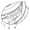
本発明によると、搾乳カップ取り付け部3と連結部2を互いに接続する、使用表示部材4が備わっている。好適な使用表示部材は、搾乳カップ取り付け部3と連結部2の間の接続を、これら二つの部分が初めて引き離されるか、初めてこの部材が取り外されるかする際に、不可逆的に破壊するなら、いかなるタイプの接続構造でもよい。
According to the present invention, the
この使用表示部材4は、好ましくは、破断オープンシール、例えば、分離時に破れる薄いウェブ41を介して、連結部2と搾乳カップ取り付け部3に接続されている円周バンドである。使用表示部材4もまた、通常、プラスチックでできており、二つの部分のどちらかの上に、または両部分2、3の上に射出成形されている。
This
使用表示部材4は、好ましくは、手で容易に掴み、容易に破ることができるように、突き出たタブ40を有する。これを図1cに示す。
The
上述の搾乳カップセットの個々の部分は、1つ以上の要素に形成することができる。これらの部分の2つ以上を、一体的に形成することもできる。 Individual portions of the above described milking cup set can be formed into one or more elements. Two or more of these parts may be integrally formed.
図1bに見られるように、第1の実施形態は、幾つかの個々の部分で構成されている。収集容器1は円筒形ビーカーであり、その上縁に、第1の下側スナップフィット密閉部材11を円周ビーズ構造で有する。連結部2が、その下縁に、第1の上側スナップフィット密閉部材20を円周ラッチ構造で有する。これら二つの部材が互いに差し込まれると、ラッチがビーズのまわりに係合し、それにより、連結部2と収集容器1の間に安定した接続が形成される。
As can be seen in FIG. 1b, the first embodiment consists of several individual parts. The
この実施形態では、搾乳カップ取り付け部3は二つの部品に設計されており、容器側コネクタ30と漏斗側コネクタ31を備えた上部部材3′を有する。搾乳カップ漏斗5は、胸に当てるための漏斗部50と、漏斗側コネクタ31に固定して取り付けるか、あるいは、漏斗側コネクタ31にはめ込み且つ容易に(漏斗側コネクタから)取り外すことができる漏斗コネクタ51を有する。
In this embodiment, the milking
搾乳カップ取り付け部3の下部部材3′′は、使用表示部材4を介して連結部2に接続されている。
The
図1dから明らかなように、弁7は、ここでは弁膜70と弁体71から構成されており、好ましくは、容器側コネクタ30の下縁に取り付けられている。
As can be seen from FIG. 1 d, the
第2の上側スナップフィット密閉部材33は、容器側コネクタ30の上に配置され、その嵌め合わせ要素34が下部部材3′′の上に形成されている。これは、図1dに容易に見ることができる。第2の上側スナップフィット密閉部材33は、好ましくは、連結部2の開口内に突き出ているコネクタの上へしっかりと引っかかる、上側及び下側円周ラッチによって形成されている。好ましくは、上部及び下部部材3′、3′′の間のこの接続は破壊されることなしにはずすことはできず、そのため、図1e、1f及び1gに見られるように、連結部2と搾乳カップ取り付け部3は、使用表示部材4によって接続された1つのユニットを形成する。
The second upper snap-
使用表示部材4が取り外されると、搾乳カップ取り付け部3の全体、すなわち、上部及び下部部材3′、3′′は、図1hに見られるように、連結部2から外れる。この分離は、両部分が再び接続されるとき、もはや十分に良好な接続を得ることができないことを意味し、そのため、この結合はミルクを搾り出すために再度使用することができない。
When the
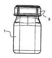
しかしながら、ビーカー型収集容器1は取り付けられた連結部2とともにあとに残され、これらがともに哺乳瓶を形成する。連結部2はボトルネックを形成する。使用表示部材4の下側に雄ネジ21が備えられているため、使用するまで瓶を蓋8によって閉じることができる。これを図1iに示す。使用時には、蓋8を取り外し、乳首の付いた上端部を公知の方法で取り付けることができる。
However, the beaker-
本発明による搾乳カップセットの第2の実施形態においては、図2aから2cに示されるように、搾乳カップ取り付け部3が一部品として形成され、使用表示部材4はその上に一体的に形成されている。ここでは、前と同じく、スナップフィット密閉と不正開封防止バンドが、連結部材2との不可逆的破壊可能な接続を保証する。この実施形態では、収集容器1と連結部2が、一体瓶(一つの瓶)によって形成されている。しかしながら、別の変形では、それらは、図1bのように二つの部分に形成される。この例においても、搾乳カップ漏斗5は、使用時に、搾乳カップ取り付け部3に差し込むことができる。
In the second embodiment of the milking cup set according to the present invention, as shown in FIGS. 2a to 2c, the milking
図3aから3cによる実施形態では、搾乳カップ漏斗5と搾乳カップ取り付け部3はともに一体に形成されている。使用表示部材4は搾乳カップ取り付け部3の下縁に形成されている。この例においても、収集容器1と連結部2は一体瓶に形成することができ、あるいは、別々の部分に形成することができる。この例においては、収集容器1が円形断面でなく、矩形断面、特に正方形断面を有する。このことは、円形瓶より少ない空間で保管できることを意味する。もちろん、上述のツーパーツ瓶もまた、そのような矩形又は正方形の形を有することができる。
In the embodiment according to FIGS. 3a to 3c, the milking
図4による実施形態では、互いに一体的に接続された、搾乳カップ取り付け部と連結部が示されている。この場合もまた、使用表示部材が、射出成形されている。 In the embodiment according to FIG. 4, a milking cup attachment part and a coupling part are shown integrally connected to each other. Also in this case, the use display member is injection molded.
図5aと5bによる実施形態では、弁7が容器側コネクタ30の上にではなく、連結部2内に突き出している嵌め合い要素34の上に配置されている。弁体71は、この嵌め合い要素34の上に取り付け、あるいは一体的に形成することができる。
In the embodiment according to FIGS. 5 a and 5 b, the
弁7は多種多様な形状を有することができる。上述の実施形態では、特に図1kにおいては、円筒形弁体71とこの弁体71を覆う膜70を有する弁7が開示されている。弁体71は、好ましくは剛体材料、特にプラスチックでできている。膜70は、可撓性材料、好ましくは、ゴム、天然ゴム、又はシリコーン又はTPE(熱可塑性エラストマー)でできている。
The
弁7は弁体71をスタブ(stub)の上にかぶせることにより、その位置に固定される。弁体71は、正面に、貫通口72と中心に配置される受け入れ口73を有する。これに合わせて、膜は、膜を固定するために受け入れ口73にはめ込むことができる、好ましくは中心に配置された接続ボタン74を有する。
The
しかしながら、他の弁もまた搾乳カップセットの上記実施形態において使用することができる。それゆえ、図6に見られるように、接続ボタンの形での膜受け78を弁体71の上に配置することができ、受け入れ口73を膜70の中に配置することができる。
However, other valves can also be used in the above embodiment of the milking cup set. Therefore, as seen in FIG. 6, a
図7aから7cに示されるように、膜70はまた、ヒンジ又はへり75を介して弁体71に一体的に接続することができる。この場合、弁7は好ましくは均一な材料からできており、膜は弁体より薄い壁を有している。
As shown in FIGS. 7 a to 7 c, the
さらに、図8a及び8bによる弁体7は、閉じたジャケットではなく、一端で開放されているジャケットを有するよう設計することができる。これによって、二つのジャケット部分76は弾力的に形成することができ、一方で、簡単に弁7を定位置に取り付けることができ、他方で、コネクタ30の上でのその嵌め合いを良くする。
Furthermore, the
図9aから9cによる他の実施形態では、膜70はウェブ77を介して弁体71上に一体的に形成されており、膜の二つの内面と弁体の内面が、同一平面にあるように形成されている。
In another embodiment according to FIGS. 9a to 9c, the
1 収集容器
11 第1の下側スナップフィット密閉部材
2 連結部
20 第1の上側スナップフィット密閉部材
21 雄ネジ
3 搾乳カップ取り付け部
3′ 上部部材
3′′ 下部部材
30 容器側コネクタ
31 漏斗側コネクタ
32 ポンプ側コネクタ
33 第2の上側スナップフィット密閉部材
34 第2の下側スナップフィット密閉部材
35 容器側入口
4 使用表示部材
40 タブ
41 ウェブ
5 搾乳カップ漏斗
50 漏斗部
51 漏斗コネクタ
6 接続チューブ
60 第2の端部
7 弁
70 弁膜
71 弁体
72 貫通口
73 受け入れ口
74 接続ボタン
75 へり
76 ジャケット部分
77 ウェブ
78 膜受け
8 密閉蓋
DESCRIPTION OF
4 Use
5 Milking
6 Connection tube 60 Second end
7
8 Sealing lid
Claims (14)
前記連結部(2)と前記搾乳カップ取り付け部(3)は、使用表示部材(4)により互いに接続され、この使用表示部材は、前記連結部(2)と前記搾乳カップ取り付け部(3)が初めて引き離されるとき、又は使用表示部材(4)が初めて取り外されるとき不可逆的に接続を破壊し、前記使用表示部材が、前記連結部(2)及び前記搾乳カップ取り付け部(3)はミルクを搾り出すために一度だけしか使用できないことを保障することを特徴とする使い捨て搾乳カップセット。It has a coupling part (2) for connection to the milk collection container (1) and a milking cup attachment part (3) for connection to the milking cup funnel (5), and the coupling part (2) and the milking cup attachment The parts (3) are connected to each other , and the connecting part (2) and the milking cup attaching part (3) need to be separated in order to store milk or to drink milk collected in a milk collection container. In disposable milking cup sets,
The connection part (2) and the milking cup attachment part (3) are connected to each other by a use display member (4), and the use display member includes the connection part (2) and the milking cup attachment part (3). When pulled away for the first time, or when the use indicator member (4) is removed for the first time, the connection is irreversibly broken, and the use indicator member squeezes the coupling part (2) and the milking cup attachment part (3). Disposable milking cup set characterized by ensuring that it can only be used once to dispense.
Applications Claiming Priority (2)
| Application Number | Priority Date | Filing Date | Title |
|---|---|---|---|
| PCT/CH2004/000334 WO2005118022A1 (en) | 2004-06-03 | 2004-06-03 | Disposable breast shield set |
| PCT/CH2005/000298 WO2005118023A1 (en) | 2004-06-03 | 2005-05-26 | Disposable breast cup set |
Publications (2)
| Publication Number | Publication Date |
|---|---|
| JP2008501378A JP2008501378A (en) | 2008-01-24 |
| JP4486681B2 true JP4486681B2 (en) | 2010-06-23 |
Family
ID=34957469
Family Applications (1)
| Application Number | Title | Priority Date | Filing Date |
|---|---|---|---|
| JP2007513649A Expired - Fee Related JP4486681B2 (en) | 2004-06-03 | 2005-05-26 | Disposable milking cup set |
Country Status (8)
| Country | Link |
|---|---|
| US (1) | US7875000B2 (en) |
| EP (1) | EP1753482B1 (en) |
| JP (1) | JP4486681B2 (en) |
| CN (1) | CN100584396C (en) |
| AT (1) | ATE540711T1 (en) |
| AU (1) | AU2005249623B2 (en) |
| PL (1) | PL1753482T3 (en) |
| WO (2) | WO2005118022A1 (en) |
Cited By (1)
| Publication number | Priority date | Publication date | Assignee | Title |
|---|---|---|---|---|
| USD988500S1 (en) | 2020-12-22 | 2023-06-06 | Pigeon Corporation | Breast pump valve |
Families Citing this family (36)
| Publication number | Priority date | Publication date | Assignee | Title |
|---|---|---|---|---|
| US6749582B2 (en) | 2002-04-30 | 2004-06-15 | The First Years Inc. | Pumping breast milk |
| JP4657345B2 (en) | 2005-04-07 | 2011-03-23 | メデラ ホールディング アーゲー | Valves, especially valves for breast cap sets |
| GB0620483D0 (en) * | 2006-10-17 | 2006-11-22 | Martin Peter J | The re:tie |
| WO2010083485A2 (en) | 2009-01-16 | 2010-07-22 | Learning Curve Brands, Inc. | Breast pump and method of use |
| US8529501B2 (en) * | 2010-06-04 | 2013-09-10 | Medela Holding Ag | One time use breastpump assembly |
| DE102011002940B4 (en) * | 2011-01-20 | 2016-06-23 | Oculus Optikgeräte GmbH | Positioning unit and observation device |
| DE102011002941B8 (en) | 2011-01-20 | 2012-10-18 | Oculus Optikgeräte GmbH | Positioning unit and observation device |
| EP3141268B1 (en) * | 2013-03-13 | 2020-08-05 | Medela Holding AG | System and container for monitoring and analyzing milk collection |
| US9616156B2 (en) | 2013-03-24 | 2017-04-11 | Naya Health, Inc. | Method, apparatus, and system for expression and quantification of human breast milk |
| US10426705B2 (en) * | 2013-09-05 | 2019-10-01 | Lansinoh Laboratories, Inc. | Colostrum collection system |
| US10080825B2 (en) * | 2013-09-05 | 2018-09-25 | Lansinoh Laboratories, Inc. | Connector for collection and dispensing of breast milk or colostrum |
| US10086120B2 (en) * | 2013-09-05 | 2018-10-02 | Lansinoh Laboratories, Inc. | Connector for collection and dispensing of breast milk or colostrum |
| US10485908B2 (en) * | 2014-02-06 | 2019-11-26 | Exploramed Nc7, Inc. | Apparatus and methods to create posterior compression at the breast during expression of breast milk |
| US10617805B2 (en) | 2014-03-20 | 2020-04-14 | Exploramed Nc7, Inc. | Fluid measuring reservoir for breast pumps |
| US10639406B2 (en) | 2014-03-20 | 2020-05-05 | Exploramed Nc7, Inc. | Methods and apparatus for transferring pressure during expression of human breast milk |
| US9623160B2 (en) | 2014-09-19 | 2017-04-18 | Naya Health, Inc. | Quantification and inventory management of expressed human breast milk |
| US10828407B2 (en) | 2014-06-23 | 2020-11-10 | Momgenuity, Llc | Breast pump kit |
| US9408957B1 (en) * | 2014-06-23 | 2016-08-09 | Sherri Levine | Breast pump shield |
| US10773860B2 (en) * | 2014-07-24 | 2020-09-15 | Al Ibtikar Packaging & Investment Co., Ltd. | Method for safe and tight closure using safety strip and cap for closing bottle's neck |
| US9931450B2 (en) | 2014-10-28 | 2018-04-03 | Inteplast Group Corporation | Breast pump adaptor and method of filling bag |
| USD763435S1 (en) * | 2014-10-28 | 2016-08-09 | Inteplast Group Corporation | Adaptor for securing a bag to a breast pump |
| ES2793350T3 (en) | 2015-04-08 | 2020-11-13 | Exploramed Nc7 Inc | Fluid measuring tank for breast pumps |
| WO2017083769A1 (en) | 2015-11-13 | 2017-05-18 | Naya Health, Inc. | Apparatus and methods to create posterior compression at the breast during expression of breast milk |
| USD862680S1 (en) * | 2016-02-10 | 2019-10-08 | Exploramed Nc7, Inc. | Container assembly for a breast pump |
| USD858744S1 (en) * | 2016-12-14 | 2019-09-03 | Moxxly, Inc. | Breast pump |
| US10016548B1 (en) | 2017-01-11 | 2018-07-10 | Carr Lane Quackenbush | Breast pump |
| US11413381B2 (en) | 2017-01-11 | 2022-08-16 | Momtech Inc. | Breast pump |
| US11116880B2 (en) | 2019-10-29 | 2021-09-14 | Momi Brands, Inc. | Manual breast pump |
| US11147905B2 (en) | 2017-01-11 | 2021-10-19 | Momi Brands, Inc. | Breast pump |
| US10617806B2 (en) | 2018-09-06 | 2020-04-14 | Lansinoh Laboratories, Inc. | Vibratory waveform for breast pump |
| WO2020051438A1 (en) | 2018-09-06 | 2020-03-12 | Lansinoh Laboratories, Inc. | Closed loop electric breast pump |
| WO2020051456A1 (en) | 2018-09-06 | 2020-03-12 | Lansinoh Laboratories, Inc. | Breast pumps |
| USD912243S1 (en) * | 2018-11-26 | 2021-03-02 | Karl Storz Se & Co. Kg | Suction cannula |
| USD898184S1 (en) | 2019-01-29 | 2020-10-06 | Handi-Craft Company | Breast pump valve |
| US11931491B2 (en) | 2020-02-19 | 2024-03-19 | Marcella Lee Post | Breast pump flange assembly and method of use |
| KR102525143B1 (en) * | 2020-05-18 | 2023-04-25 | 황민석 | Medical suction device |
Family Cites Families (25)
| Publication number | Priority date | Publication date | Assignee | Title |
|---|---|---|---|---|
| GB550187A (en) * | 1941-01-09 | 1942-12-28 | Eskil Julius Gavatin | Improvements in or relating to breast pumps |
| US4772262A (en) * | 1985-04-16 | 1988-09-20 | Natural Technologies, Inc. | Portable electric breast pump |
| US4798301A (en) * | 1987-12-14 | 1989-01-17 | Cap Snap Co. | Tamper-resistant cap for wide mouth jar |
| JP2589532B2 (en) | 1988-03-23 | 1997-03-12 | 日本クラウンコルク株式会社 | Tamper-evident display lid |
| JPH04231964A (en) * | 1990-07-10 | 1992-08-20 | Isg Ag | Mammary pump for milk |
| US5308321A (en) * | 1992-05-05 | 1994-05-03 | Castro Donna J | Retainer assisted by vacuum expansion system |
| US5775528A (en) * | 1995-08-21 | 1998-07-07 | Superseal Corporation | Snap-on/screw-off cap and neck configuration |
| US6110140A (en) * | 1996-09-17 | 2000-08-29 | Medela, Inc. | Manual breastmilk pump |
| US6112923A (en) * | 1997-08-01 | 2000-09-05 | Portola Packaging, Inc. | Tamper evident bottle cap |
| US5941847A (en) * | 1998-02-06 | 1999-08-24 | Medela Holding Ag | Breast shield with vacuum isolation element |
| AU3328799A (en) * | 1998-03-06 | 1999-09-20 | Ameda Ag Medical Equipment | Breast pump |
| US6383163B1 (en) * | 1998-05-04 | 2002-05-07 | Patricia Ann Kelly | Electric breast pump designed to simulate infant suckling |
| US6974439B1 (en) * | 1999-06-23 | 2005-12-13 | L. Jason Clute | Apparatus for expressing milk |
| US6328082B1 (en) | 2000-03-07 | 2001-12-11 | Bbtresor Inc. | Disposable sterile bag, e.g. for breast milk |
| JP2002302133A (en) | 2001-04-05 | 2002-10-15 | Toyobo Co Ltd | Cap for bottle |
| JP2002336347A (en) * | 2001-05-18 | 2002-11-26 | Univ Nihon | Breast pump |
| US6663587B2 (en) * | 2001-06-22 | 2003-12-16 | Medela Holding Ag | Breastshield with multi-pressure and expansible chamber construction, related breastpump and method |
| CN100515876C (en) * | 2001-08-13 | 2009-07-22 | 奥布里斯特闭合件瑞士有限责任公司 | Closure cap and an assembly of the closure cap and a container neck |
| JP2003235960A (en) * | 2002-02-14 | 2003-08-26 | Koshin Baby Co Ltd | Milker |
| US6616000B1 (en) * | 2002-04-19 | 2003-09-09 | Playtex Products, Inc. | Infant feeding and storage system |
| US6749582B2 (en) * | 2002-04-30 | 2004-06-15 | The First Years Inc. | Pumping breast milk |
| US6732773B2 (en) * | 2002-06-18 | 2004-05-11 | Playtex Products, Inc. | Cover assembly for use with a breast milk storage system |
| US20040087898A1 (en) * | 2002-11-01 | 2004-05-06 | Gotthilf Weniger | Breast pump assembly |
| US7776008B2 (en) * | 2003-08-08 | 2010-08-17 | Playtex Products, Inc. | Manual breast pump |
| US20060148380A1 (en) * | 2004-08-10 | 2006-07-06 | Playtex Products, Inc. | Breast cup |
-
2004
- 2004-06-03 WO PCT/CH2004/000334 patent/WO2005118022A1/en active Application Filing
-
2005
- 2005-05-26 CN CN200580017628A patent/CN100584396C/en not_active Expired - Fee Related
- 2005-05-26 AT AT05742280T patent/ATE540711T1/en active
- 2005-05-26 PL PL05742280T patent/PL1753482T3/en unknown
- 2005-05-26 US US11/578,635 patent/US7875000B2/en not_active Expired - Fee Related
- 2005-05-26 WO PCT/CH2005/000298 patent/WO2005118023A1/en not_active Application Discontinuation
- 2005-05-26 AU AU2005249623A patent/AU2005249623B2/en not_active Ceased
- 2005-05-26 EP EP05742280A patent/EP1753482B1/en not_active Not-in-force
- 2005-05-26 JP JP2007513649A patent/JP4486681B2/en not_active Expired - Fee Related
Cited By (1)
| Publication number | Priority date | Publication date | Assignee | Title |
|---|---|---|---|---|
| USD988500S1 (en) | 2020-12-22 | 2023-06-06 | Pigeon Corporation | Breast pump valve |
Also Published As
| Publication number | Publication date |
|---|---|
| JP2008501378A (en) | 2008-01-24 |
| AU2005249623A1 (en) | 2005-12-15 |
| CN100584396C (en) | 2010-01-27 |
| ATE540711T1 (en) | 2012-01-15 |
| WO2005118022A1 (en) | 2005-12-15 |
| US7875000B2 (en) | 2011-01-25 |
| US20070173756A1 (en) | 2007-07-26 |
| WO2005118023A1 (en) | 2005-12-15 |
| EP1753482B1 (en) | 2012-01-11 |
| AU2005249623B2 (en) | 2010-09-02 |
| PL1753482T3 (en) | 2012-05-31 |
| CN1960773A (en) | 2007-05-09 |
| EP1753482A1 (en) | 2007-02-21 |
Similar Documents
| Publication | Publication Date | Title |
|---|---|---|
| JP4486681B2 (en) | Disposable milking cup set | |
| CA2477666C (en) | Wet tissues dispenser | |
| US8715255B2 (en) | Fastening device for a drainage container | |
| RU2502655C2 (en) | Lid | |
| MX2011000490A (en) | Closure with utensil. | |
| WO2003093127A1 (en) | Dispensing container | |
| JP2007089904A (en) | Breast pump | |
| KR200441528Y1 (en) | Cover of airtight container | |
| JPH06199373A (en) | Wet tissue container | |
| US20050269376A1 (en) | Cap for cup | |
| EP4238449A1 (en) | Contents container | |
| KR101605849B1 (en) | Fat transplantation container | |
| CN215584840U (en) | Portable drinking medicine box | |
| JP3894358B2 (en) | Pouring cap | |
| CN113631072A (en) | Cloth dispenser and packaging unit thereof | |
| US10364083B2 (en) | Break-off spout, pouch having a break-off spout, production method for pouch having a break-off spout, food or beverage in pouch having a break-off spout, and production method therefor | |
| CN210823565U (en) | Disposable plastic food containing box | |
| WO2003047996A1 (en) | Liquid container | |
| CN212213330U (en) | Cup cover | |
| CN210592949U (en) | Plastic food packaging box with sealing box cover | |
| JP4486679B2 (en) | Drainage bag | |
| JP3720569B2 (en) | Synthetic resin pouring container | |
| JP4932469B2 (en) | Cotton swab packaging container | |
| JPH0644813Y2 (en) | Fluid packaging container | |
| JPH0644814Y2 (en) | Packaging container spout |
Legal Events
| Date | Code | Title | Description |
|---|---|---|---|
| A621 | Written request for application examination |
Free format text: JAPANESE INTERMEDIATE CODE: A621 Effective date: 20080414 |
|
| RD03 | Notification of appointment of power of attorney |
Free format text: JAPANESE INTERMEDIATE CODE: A7423 Effective date: 20080417 |
|
| A521 | Request for written amendment filed |
Free format text: JAPANESE INTERMEDIATE CODE: A821 Effective date: 20080417 |
|
| A977 | Report on retrieval |
Free format text: JAPANESE INTERMEDIATE CODE: A971007 Effective date: 20091022 |
|
| A131 | Notification of reasons for refusal |
Free format text: JAPANESE INTERMEDIATE CODE: A131 Effective date: 20091110 |
|
| A521 | Request for written amendment filed |
Free format text: JAPANESE INTERMEDIATE CODE: A523 Effective date: 20100209 |
|
| TRDD | Decision of grant or rejection written | ||
| A01 | Written decision to grant a patent or to grant a registration (utility model) |
Free format text: JAPANESE INTERMEDIATE CODE: A01 Effective date: 20100316 |
|
| A01 | Written decision to grant a patent or to grant a registration (utility model) |
Free format text: JAPANESE INTERMEDIATE CODE: A01 |
|
| A61 | First payment of annual fees (during grant procedure) |
Free format text: JAPANESE INTERMEDIATE CODE: A61 Effective date: 20100326 |
|
| R150 | Certificate of patent or registration of utility model |
Ref document number: 4486681 Country of ref document: JP Free format text: JAPANESE INTERMEDIATE CODE: R150 Free format text: JAPANESE INTERMEDIATE CODE: R150 |
|
| FPAY | Renewal fee payment (event date is renewal date of database) |
Free format text: PAYMENT UNTIL: 20130402 Year of fee payment: 3 |
|
| FPAY | Renewal fee payment (event date is renewal date of database) |
Free format text: PAYMENT UNTIL: 20130402 Year of fee payment: 3 |
|
| FPAY | Renewal fee payment (event date is renewal date of database) |
Free format text: PAYMENT UNTIL: 20140402 Year of fee payment: 4 |
|
| R250 | Receipt of annual fees |
Free format text: JAPANESE INTERMEDIATE CODE: R250 |
|
| R250 | Receipt of annual fees |
Free format text: JAPANESE INTERMEDIATE CODE: R250 |
|
| R250 | Receipt of annual fees |
Free format text: JAPANESE INTERMEDIATE CODE: R250 |
|
| R250 | Receipt of annual fees |
Free format text: JAPANESE INTERMEDIATE CODE: R250 |
|
| R250 | Receipt of annual fees |
Free format text: JAPANESE INTERMEDIATE CODE: R250 |
|
| R250 | Receipt of annual fees |
Free format text: JAPANESE INTERMEDIATE CODE: R250 |
|
| LAPS | Cancellation because of no payment of annual fees |