JP4485874B2 - Mold assembly apparatus, mold press molding apparatus, mold assembly method, and molded body manufacturing method - Google Patents
Mold assembly apparatus, mold press molding apparatus, mold assembly method, and molded body manufacturing method Download PDFInfo
- Publication number
- JP4485874B2 JP4485874B2 JP2004219237A JP2004219237A JP4485874B2 JP 4485874 B2 JP4485874 B2 JP 4485874B2 JP 2004219237 A JP2004219237 A JP 2004219237A JP 2004219237 A JP2004219237 A JP 2004219237A JP 4485874 B2 JP4485874 B2 JP 4485874B2
- Authority
- JP
- Japan
- Prior art keywords
- mold
- lower mold
- molding
- die
- mounting table
- Prior art date
- Legal status (The legal status is an assumption and is not a legal conclusion. Google has not performed a legal analysis and makes no representation as to the accuracy of the status listed.)
- Expired - Lifetime
Links
- 238000000465 moulding Methods 0.000 title claims description 90
- 238000000034 method Methods 0.000 title claims description 19
- 238000004519 manufacturing process Methods 0.000 title claims description 16
- 239000012778 molding material Substances 0.000 claims description 21
- 238000001514 detection method Methods 0.000 claims description 15
- 230000003028 elevating effect Effects 0.000 claims description 7
- 230000000630 rising effect Effects 0.000 claims description 6
- 230000006835 compression Effects 0.000 claims description 5
- 238000007906 compression Methods 0.000 claims description 5
- 238000010438 heat treatment Methods 0.000 claims description 4
- 238000013459 approach Methods 0.000 claims description 2
- 239000011521 glass Substances 0.000 description 19
- 230000003287 optical effect Effects 0.000 description 11
- 238000003825 pressing Methods 0.000 description 9
- 238000012545 processing Methods 0.000 description 6
- 230000001965 increasing effect Effects 0.000 description 3
- 230000003139 buffering effect Effects 0.000 description 2
- 230000003247 decreasing effect Effects 0.000 description 2
- 239000000463 material Substances 0.000 description 2
- 230000002093 peripheral effect Effects 0.000 description 2
- 230000001174 ascending effect Effects 0.000 description 1
- 239000000919 ceramic Substances 0.000 description 1
- 238000010586 diagram Methods 0.000 description 1
- 238000002474 experimental method Methods 0.000 description 1
- 238000003384 imaging method Methods 0.000 description 1
- 238000003780 insertion Methods 0.000 description 1
- 230000037431 insertion Effects 0.000 description 1
- 238000012423 maintenance Methods 0.000 description 1
- 230000002265 prevention Effects 0.000 description 1
- 238000007493 shaping process Methods 0.000 description 1
- 238000010583 slow cooling Methods 0.000 description 1
Images


Classifications
-
- C—CHEMISTRY; METALLURGY
- C03—GLASS; MINERAL OR SLAG WOOL
- C03B—MANUFACTURE, SHAPING, OR SUPPLEMENTARY PROCESSES
- C03B11/00—Pressing molten glass or performed glass reheated to equivalent low viscosity without blowing
- C03B11/06—Construction of plunger or mould
- C03B11/08—Construction of plunger or mould for making solid articles, e.g. lenses
-
- C—CHEMISTRY; METALLURGY
- C03—GLASS; MINERAL OR SLAG WOOL
- C03B—MANUFACTURE, SHAPING, OR SUPPLEMENTARY PROCESSES
- C03B11/00—Pressing molten glass or performed glass reheated to equivalent low viscosity without blowing
- C03B11/16—Gearing or controlling mechanisms specially adapted for glass presses
-
- C—CHEMISTRY; METALLURGY
- C03—GLASS; MINERAL OR SLAG WOOL
- C03B—MANUFACTURE, SHAPING, OR SUPPLEMENTARY PROCESSES
- C03B2215/00—Press-moulding glass
- C03B2215/72—Barrel presses or equivalent, e.g. of the ring mould type
Landscapes
- Engineering & Computer Science (AREA)
- Chemical & Material Sciences (AREA)
- Manufacturing & Machinery (AREA)
- Materials Engineering (AREA)
- Organic Chemistry (AREA)
- Moulds For Moulding Plastics Or The Like (AREA)
Description
本発明は、プレス成形によって成形体(例えば、高精度ガラスレンズなどの光学素子)を製造する際、所望の光学素子形状にもとづいて精密加工を施した上型、下型、胴型からなる成形型内に成形素材を配置し、成形型を組み立てる組立装置及び組立方法に関する。また、本発明は、前記組立装置を備えたモールドプレス成形装置及び、この成形装置を用いた成形体の製造方法に関する。 In the present invention, when a molded body (for example, an optical element such as a high-precision glass lens) is manufactured by press molding, molding is made of an upper mold, a lower mold, and a body mold that have been subjected to precision processing based on a desired optical element shape. The present invention relates to an assembling apparatus and an assembling method for arranging a molding material in a mold and assembling the molding die. The present invention also relates to a mold press molding apparatus provided with the assembling apparatus and a method for producing a molded body using the molding apparatus.
精密加工された成形型を用い、軟化ガラスを融着させることなく、高精度ガラスレンズなどの光学素子をプレス成形する方法が種々開発されてきている(例えば、特許文献1、2参照。)。プレス成形によって、要求されるレンズを得るには、良好な外観、表面形状精度、肉厚、外径、さらに偏心などの様々な規格を満足させなければならない。
Various methods have been developed for press molding optical elements such as high-precision glass lenses using a precision-worked mold without fusing softened glass (see, for example,
特許文献1には、ガラスプリフォームの取り入れ室、加熱室、プレス室、徐冷室及びレンズの取り出し室からなり、全体が真空排気可能であり、かつ金型及び/又はガラスを順次移送する手段を設けたプレスレンズの製造装置が記載されている。このような装置によると、複数組の型を用いて連続的に動作させることにより、非常に速いスピードで高い面精度のプレスレンズを製造できるとともに、型寿命を長くすることができる。
また、特許文献2には、上型、下型、胴型からなる成形型を、被成形物の充填及び取り出しのために組立及び分解する装置において、成形型の分解時に下型を胴型の中心軸線に垂直な方向に移動可能な状態で保持する保持手段を有する台と、胴型を台の上方において固定保持するための保持固定手段と、台の昇降手段を備えた、成形型の分解、組立装置が記載されている。
特許文献1に記載の製造装置によれば、高い処理スピードで連続的に成形体を得ることができ、型寿命も長くなるという利点がある。しかしながら、この装置では、上型、下型とプレス軸が連結しておらず、成形型が単独で移送されるため、プレス軸の駆動によって上型と下型を離間させて、成形体の取り出しや成形素材の供給を行うことができない。すなわち、成形型に成形素材を配置したり、成形型内から成形体を取り出すためには、成形型の組立及び/又は分解のための工夫が必要となる。また、成形型の組立、分解の工程に安定性と迅速性がないと、この工程が律速となり、実際に高いスピードで成形体を得ることができない。
According to the manufacturing apparatus described in
特許文献2の装置によれば、成形型の分解、組立を手作業から機械化するにあたり、下型と胴型の間に若干のずれや傾きが生じていても、下型と胴型の間に大きな抵抗を生じさせずに、分解、組立をスムーズに行うことができる。しかしながら、この装置によって成形型を組み立てる際、胴型と下型のクリアランスが十分である場合には問題がないが、クリアランスが小さくなるとある頻度で下型と胴型の噛み込みが生じることを防止しきれず、度々動作が停止されることが見出された。
According to the apparatus of
また、特許文献2の装置によれば、成形型の分解作業に際して、下型を載置台に真空吸着した状態で下型を降下させている。一方、成形型の組立作業の場合には、下型を真空吸着せずに載置台を上昇させて胴型に嵌め込んでいる。このような装置の場合、本発明者らの実験によると、下型が降下した状態で、下型と載置台の間の真空吸着を解除するとき、あるいは、載置台の昇降運動の際に、載置台にわずかな振動が生じやすい。そして、このような振動によって載置台上の下型位置がわずかにずれると、上記のような噛み込みや型破損が生じ易くなることを見出した。
Further, according to the apparatus of
そこで、成形型の分解及び組立に際し、一貫して真空吸着を作動させておくことによって、載置台に下型を一体的に保持したままで、成形体の取り出しと成形素材の供給を行ったところ、下型と胴型の噛み込みによる動作停止頻度は減少した。しかし、十分とはいえなかった。 Therefore, when disassembling and assembling the mold, the vacuum suction is operated consistently, so that the molded body is taken out and the molding material is supplied while the lower mold is integrally held on the mounting table. The frequency of operation stoppage due to the biting of the lower mold and the trunk mold decreased. However, it was not enough.
現在、モールドプレスレンズに要求される偏心精度は、きわめて厳しくなっている。例えば、デジタルカメラ等の小型撮像機器においては、数メガの画素数の撮像を可能とするため、あるいは、光記録再生装置の光学系においては、記録密度の増大による開口数の増大などにより、成形時の偏心量は、成形シフト(成形されるレンズの光軸と垂直の方向への上下型の相互のシフト量)、成形ティルト(成形されるレンズの第一面と第二面を成形する、上型と下型の軸の傾き)のいずれにおいても厳しく制限されている。例えば、成形シフトが5μm以下、成形ティルトが2分以下のものが挙げられる。このような光学素子をモールドプレスで成形するためには、上下型と胴型の寸法精度を極めて高くするとともに、その摺動クリアランスは、5μm以下、好ましくは、3μm以下とする必要がある。これにともない、成形型の分解、組立に際して、きわめて精緻な動作を行わないと、噛み込みが生じ、さらには型破損により、所望の球面又は非球面などの精密加工を施した高価な上下型や胴型に損傷が生じる。 Currently, the eccentric accuracy required for mold press lenses has become extremely strict. For example, in a small imaging device such as a digital camera, it is possible to form an image with several megapixels, or in the optical system of an optical recording / reproducing apparatus, the numerical aperture is increased by increasing the recording density. The amount of eccentricity is the molding shift (the amount of shift of the upper and lower molds in the direction perpendicular to the optical axis of the molded lens), the molding tilt (molding the first and second surfaces of the molded lens, Both the upper mold and the lower mold are tilted strictly. For example, a molding shift is 5 μm or less and a molding tilt is 2 minutes or less. In order to mold such an optical element with a mold press, the dimensional accuracy of the upper and lower molds and the barrel mold must be extremely high, and the sliding clearance must be 5 μm or less, preferably 3 μm or less. As a result, if the mold is not disassembled and assembled, if an extremely precise operation is not performed, biting occurs. Damage to the body mold occurs.
本発明は、上記の事情にかんがみなされたものであり、成形型の組立に際し、きわめて精緻な動作を可能とし、下型と胴型の噛み込みを防ぐことによって型の損傷を防止した成形型の組立装置及び組立方法の提供を目的とする。また、前記成形型の組立装置を備えることによって、高い処理速度で、連続的に成形体を成形することのできるモールドプレス成形装置、及び、この成形装置を用いた成形体の製造方法の提供を目的とする。 The present invention has been considered in view of the above circumstances, and is capable of very precise operation when assembling the mold, and prevents the mold from being damaged by preventing the lower mold and the body mold from being caught. An object is to provide an assembling apparatus and an assembling method. In addition, by providing the molding die assembly apparatus, a mold press molding apparatus capable of continuously molding a molded body at a high processing speed, and a molded body manufacturing method using the molding apparatus are provided. Objective.
上記目的を達成するため本発明のモールドプレス成形型は、上型と下型及び胴型を有する成形型を組み立てる成形型の組立装置において、前記胴型を固定する固定手段と、前記下型を載置する載置台と、この載置台に載置された下型を保持する保持手段と、前記載置台を昇降させる昇降手段と、前記載置台の上昇により、前記下型が前記胴型に接近した所定位置に達したことを検知する検知手段と、前記昇降手段の駆動を制御するとともに、前記検知手段による前記所定位置の検知にもとづいて、前記保持手段の保持を解除して前記下型を移動可能とする制御手段を備えた構成としてある。 In order to achieve the above object, a mold press mold of the present invention comprises: a molding means for assembling a mold having an upper mold, a lower mold, and a cylinder mold; and a fixing means for fixing the cylinder mold, and the lower mold. A mounting table, a holding means for holding the lower mold mounted on the mounting table, an elevating means for moving the mounting table up and down, and the lower mold approaching the trunk mold by raising the mounting table The detection means for detecting that the predetermined position has been reached and the drive of the elevating means are controlled, and based on the detection of the predetermined position by the detection means, the holding means is released to release the lower mold. The control unit is configured to be movable.
このように、下型を胴型に嵌め込む直前まで、下型を載置台に固定しておき、胴型に嵌め込むときには、下型を移動可能とすることにより、載置台上昇時の振動による下型のずれを防止し、かつ、胴型への嵌め込み時には、下型が移動しながら胴型へ嵌め込まれるので、胴型と下型との間で、噛み合いを生じることなく成形型を組み立てることができる。この結果、組立中の装置停止が飛躍的に少なくなった。 Thus, until the lower mold is fitted into the trunk mold, the lower mold is fixed to the mounting table, and when the lower mold is fitted into the trunk mold, the lower mold can be moved, so that the lower mold can move. The lower mold is prevented from slipping, and when it is fitted into the barrel mold, the lower mold moves and is fitted into the trunk mold, so the mold can be assembled without causing any meshing between the barrel mold and the lower mold. Can do. As a result, the number of equipment stops during assembly has been greatly reduced.
また、本発明の成形型の組立装置は、前記昇降手段が、前記下型が所定位置に達するまで前記載置台を上昇させる第1の駆動手段と、前記下型が所定位置に達した後に前記載置台を上昇させる第2の駆動手段を有する構成としてある。
このように、昇降手段として二つの駆動手段を用いると昇降手段の制御が容易となる。
In the molding die assembling apparatus of the present invention, the elevating means includes a first driving means for raising the mounting table until the lower mold reaches a predetermined position, and a front drive after the lower mold reaches the predetermined position. The second driving means for raising the writing table is provided.
Thus, when two drive means are used as the raising / lowering means, the raising / lowering means can be easily controlled.
また、本発明の成形型の組立装置は、前記第1の駆動手段から前記第2の駆動手段への駆動の切り替えを、前記下型が所定位置に達したときに、前記制御手段からの駆動信号を切り替えて行う構成としてある。
このようにすると、駆動手段の切り替えと、載置台による下型保持の解除を同期させて行うことができる。
さらに、好ましくは、前記第1の駆動手段による前記載置台の上昇速度を、前記第2の駆動手段による載置台の上昇速度より速くした構成としてある。
このようにすると、下型が所定の位置に達するまでの載置台の上昇速度を高速とし、下型を胴型に嵌め込むときの速度を緩やかにすることができる。
また、第2の駆動手段に緩衝効果を持たせることが可能となり、下型と胴型の噛み込みによって組立が失敗したときであっても、型破損が起きにくい。
Further, the molding die assembly apparatus of the present invention switches the drive from the first drive means to the second drive means when the lower mold reaches a predetermined position. The configuration is such that the signal is switched.
If it does in this way, switching of a drive means and cancellation | release of the lower mold | type holding | maintenance by a mounting base can be performed synchronizing.
Further, preferably, the rising speed of the mounting table by the first driving means is faster than the rising speed of the mounting table by the second driving means.
In this way, the ascending speed of the mounting table until the lower mold reaches a predetermined position can be increased, and the speed when the lower mold is fitted into the trunk mold can be decreased.
In addition, the second driving means can have a buffering effect, and even when the assembly fails due to the biting between the lower mold and the body mold, the mold is hardly damaged.
また、本発明の成形型の組立装置は、前記第1の駆動手段がアクチュエータを用い、前記第2の駆動手段が媒体の圧縮圧を利用したアクチュエータを用いた構成としてある。
このようにすると、第1及び第2の駆動手段として適切なアクチュエータを採用することができる。
ここで、前記下型の保持手段として、載置台に開口部を有する吸引手段を採用することが好ましい。
このようにすると、下型の保持及び解除を確実に行うとともに、制御を行いやすい。
In the molding die assembling apparatus of the present invention, the first driving means uses an actuator, and the second driving means uses an actuator using the compression pressure of the medium.
If it does in this way, a suitable actuator can be employ | adopted as a 1st and 2nd drive means.
Here, as the lower mold holding means, it is preferable to employ a suction means having an opening in the mounting table.
In this way, the lower mold can be securely held and released, and control can be easily performed.
本発明のモールドプレス成形装置は、上記成形型の組立装置を有し、かつ、成形型に載置した成形素材を加熱して軟化させた後、プレス成形して成形体を製造する構成としてある。
このようにすると、速い処理速度で、連続的に成形体を成形することが可能となる。
The mold press molding apparatus of the present invention has the above-described mold assembly apparatus, and is configured to heat and soften a molding material placed on the molding mold and then press mold to manufacture a molded body. .
If it does in this way, it becomes possible to shape | mold a molded object continuously with a high processing speed.
本発明における成形型の組立方法は、相対向する成形面を有する上型と下型、及び、前記下型側の開口部内周縁にテーパ状の案内部を形成した胴型とを含む成形型を組み立てる成形型の組立方法において、前記成形素材を前記成形面に配置した前記下型を載置台に保持する工程と、前記載置台を上昇させることにより、前記下型が前記胴型の案内部に接近したとき、前記下型の保持を解除して移動可能とする工程と、前記載置台をさらに上昇させ、移動可能となった前記下型を前記案内部によってガイドしながら前記胴型の内部に収納する工程を有する方法としてある。 A method for assembling a molding die according to the present invention includes a molding die including an upper die and a lower die having opposite molding surfaces, and a body die having a tapered guide portion formed on the inner periphery of the opening on the lower die side. In the assembling method of the molding die to be assembled, a step of holding the lower mold in which the molding material is arranged on the molding surface on the mounting table, and raising the mounting table, the lower mold becomes a guide part of the trunk mold When approaching, releasing the holding of the lower mold and making it movable, raising the mounting table further, guiding the lower mold that has become movable to the inside of the trunk mold while being guided by the guide portion This is a method having a storing step.
本発明の成形体の製造方法は、前記成形型の組立方法によって、成形素材が充填された前記成形型の組立を行い、かつ、成形型内で加熱により軟化した成形素材をプレス成形することによって成形体を製造する方法としてある。
また、前記下型を保持した状態で前記載置台を下降させることによって前記胴型から離し、その後、前記下型の成形面から前記成形体を取り除く工程を有する方法とすることが好ましい。
さらに、前記下型を保持したまま、前記成形体を取り除いた前記下型の成形面に成形素材を配置する工程を有する方法とすることが好ましい。
このようにすると、連続的に高精度の成形体を成形することが可能となる。
The method for producing a molded body of the present invention comprises assembling the molding die filled with the molding material by the molding die assembling method, and press molding the molding material softened by heating in the molding die. This is a method for producing a molded body.
Further, it is preferable that the method includes a step of lowering the mounting table in a state where the lower mold is held to separate the table from the body mold and then removing the molded body from the molding surface of the lower mold.
Furthermore, it is preferable to have a method of placing a molding material on the molding surface of the lower mold from which the molded body is removed while holding the lower mold.
If it does in this way, it will become possible to shape | mold a highly accurate molded object continuously.
以上のように、本発明によれば、きわめて摺動クリアランスが小さく、嵌合精度の高い上下型と胴型の組立を確実に安定して行うことができる。
特に、成形型は、セラミクスや超硬などの素材を、きわめて精緻な形状に加工したものであり、このような高価な成形型の破損防止は、量産上のメリットが大きい。
As described above, according to the present invention, it is possible to reliably and stably assemble the upper and lower molds and the trunk mold with extremely small sliding clearance and high fitting accuracy.
In particular, the mold is obtained by processing a material such as ceramics or cemented carbide into a very precise shape, and the prevention of damage to such an expensive mold has a great advantage in mass production.
以下、本発明の実施形態について、図面を参照して説明する。
図1は、本発明の実施形態にかかる成形型の組立装置の平面図であり、図2は、図1の縦中央断面図であり、成形素材を下型に載置した状態を示している。
Hereinafter, embodiments of the present invention will be described with reference to the drawings.
FIG. 1 is a plan view of a molding die assembling apparatus according to an embodiment of the present invention, and FIG. 2 is a longitudinal center sectional view of FIG. 1, showing a state in which a molding material is placed on a lower die. .
これら図面に示すように、成形型1は、下型2、上型3及び円筒状の胴型4からなっている。成形型1は、図示しないガラス成形体のプレス成形装置から取出された状態においては、下型2が胴型4に嵌合しており、ガラス成形体Sは下型2と上型3の間に位置している。
As shown in these drawings, the
載置台5は成形型1の下方に位置し、下型2を載置する。この載置台5は、平滑で水平な上面5aを備えている。保持手段6は、成形型1の下型2を保持するためのものであり、載置台5の上面5aに形成された円筒状の吸引孔6aと、この吸引孔6aにパイプ6b及び配管(図示せず)を介して接続する真空ポンプ(図示せず)、及び配管中に介在する切替弁6cとを有している。これにより、保持手段6は、下型2を真空吸着によって載置台5の上面5aに保持することを可能としている。また、切替弁6cを作動させ、吸引孔6aにおける吸着を解除することによって、下型2が載置台5の上面5aで移動できるようになる。
なお、保持手段6としては、真空吸着式のものに限らず、他の保持手段、例えば機械式の保持手段を採用することもできる。
The mounting table 5 is located below the
The holding means 6 is not limited to a vacuum suction type, and other holding means, for example, a mechanical holding means, can be employed.
載置台5は、第1の駆動手段7及び第2の駆動手段8からなる昇降手段によって昇降される。第1の駆動手段7は、アクチュエータとしてボールスクリュ7aを回転させるサーボモータを用い、第2の駆動手段8は、アクチュエータとしてエアシリンダを用いている。第1の駆動手段7と第2の駆動手段8は、移動台9を介して一体化している。
また、ボールスクリュ7aの長手方向と平行にスライドガイド27が設置されるとともに、このスライドガイド27に沿って昇降するスライダ28が移動台9の一端に連結されている。このような構成により、第1の駆動手段としてのサーボモータ7が回転すると、ボールスクリュウ7aを介して移動台9が鉛直方向へ昇降し、この移動台9に取り付けられている第2の駆動手段としてのエアシリンダ8は、移動台9とともに昇降する。そして、エアシリンダ8のピストンロッド8aの先端に、載置台5が固定され、エアシリンダの作動により、載置台5が昇降する。
成形型1は、位置決め手段14と押圧手段16からなる固定手段によって位置決めと保持が行われる。位置決め手段14には、上から見た形がV字形であり、かつ、ほぼ鉛直な基準面15が形成してある。この位置決め手段14は、支持部材(図示せず)に固定されている。
The mounting table 5 is lifted and lowered by lifting and lowering means including first driving means 7 and second driving means 8. The first driving means 7 uses a servo motor that rotates the
A
The molding die 1 is positioned and held by fixing means including positioning means 14 and pressing means 16. The positioning means 14 is formed with a V-shaped shape viewed from above and a substantially
押圧手段16は、載置台5の上方において、胴型4を位置決め手段14とともに保持するためのものであり、位置決め手段14とほぼ同じ高さに配置してある。押圧手段16は、位置決め手段14の基準面15に対向する挟持面17を有する板状の挟持体18と、この挟持体18を保持し水平方向に移動させるエアシリンダ19及びピストンロッド19aとからなっている。エアシリンダ19を作動させ、ピストンロッド19aを図において左方向へ水平に移動させることによって、挟持体18を胴型4の側面に当接させ、成形型1全体を位置決め手段14の基準面15に押し付け、それにより胴型4を基準面15と挟持面17との間でほぼ鉛直に保持(固定)する。
The pressing means 16 is for holding the
上記した保持手段6の切替弁6cの作動制御、押圧手段16におけるエアシリンダ19の作動制御、サーボモータ7の作動制御及び、後述する検知手段からの下型検知信号にもとづくサーボモータ7からエアシリンダ8への作動切り替えの制御は、制御装置10(図4参照)からの信号によって行われる。この制御装置10は、通常、本成形型の組立装置を有する成形(製造)装置における制御装置等と兼用する。成形型組立装置の制御も、成形装置における制御の一環として行われることが多いからである。
From the servo motor 7 to the air cylinder based on the operation control of the switching
次に、成形型の組立及び分解作業について説明する。
成形型の組立は、成形されたガラス成形体Sを下型2から取り出した後に行われる。
すなわち、ガラス成形体のプレス成形装置(図示せず)内で所定の処理がなされ、成形が完了した成形型1は、プレス成形装置の取出し室で、下型2が図示しない成形型搬送装置によってチャックされ、載置台5の上へ搬送載置される。
Next, the assembly and disassembly operations of the mold will be described.
The assembly of the mold is performed after the molded glass molded body S is taken out from the
That is, a predetermined process is performed in a glass molding press molding apparatus (not shown), and molding is completed. The molding die 1 is a take-out chamber of the press molding apparatus, and the
載置台5は、予め、サーボモータ7及び/又はエアシリンダ8によって、胴型4の保持固定に好適な位置まで上昇し、停止している。成形型搬送装置は、成形型1を載置台5上に確実に搬送するものでなければならないが、載置位置の精度は要求されない(載置台5の中心軸線と成形型1の中心軸線が一致していなくてもよい)。
続いて、位置決め手段14と押圧手段16からなる固定手段によって成形型の位置決めと固定を行う。すなわち、押圧手段16のシリンダ19が作動し、ピストンロッド19aが胴型4に向かって前進し、挟持体18の挟持面17が胴型4を基準面15に押し付け、胴型4をほぼ鉛直に固定する。
The mounting table 5 is raised to a position suitable for holding and fixing the
Subsequently, the mold is positioned and fixed by the fixing means including the positioning means 14 and the pressing means 16. That is, the
次に、図示していない真空ポンプを作動させ、パイプ6bを介して吸引孔6a内を減圧する。このとき、載置台5の上面5a及び下型2の下面が平滑に仕上げられているので、吸引孔6a内の減圧により、下型2は載置台5の上面5aに真空吸着される。このときの真空度は、成形型1のサイズ、ガラス成形体の形状および吸引6aの大きさ等により異なるが、約30torr以下とする。
そして、エアシリンダ8によってピストンロッド8aを下げることにより、下型2及びガラス成形体Sは載置台5とともに降下し、胴型4から取出される。
Next, a vacuum pump (not shown) is operated to decompress the inside of the suction hole 6a through the
Then, by lowering the
このように、下型2を真空吸着してエアシリンダ8により下降させる理由は、下型2の外径と胴型4の内径との間のクリアランスが数μmしかないため、下型2の側壁と胴型4の内側壁との間の摩擦抵抗が大きく、下型2とガラス成形体5の自重だけでは、下型2とガラス成形体5が胴型4から抜け難いためである。なお、載置台5の吸引孔6a開口部の周囲にOリングを設けると、下型2の真空吸着作用が高まる。
下型2及びガラス成形体Sが胴型4から取り出されると、エアシリンダ8の駆動がサーボモータ7の駆動に切り替わり、さらに下型2とガラス成形体Sが降下し、下型2と胴型4の間に十分な空間が形成される。そして、十分な空間が形成されたときに、図示しない吸着アームなどにより、下型2から成形体Sが取り除かれる。
Thus, the reason why the
When the
このあと、吸引孔6aからの吸引を継続したままで、下型成形面上に新たな成形素材Pを供給し、次のプレス成形サイクルの準備を行う。成形型1の組立て作業の場合には先ず、成形素材(ガラスプリフォームなど)Pを下型2の成形面に載置する。組立て作業時における下型2の上昇は、次のような二段階で行うことが好ましい。
Thereafter, with the suction from the suction hole 6a being continued, a new molding material P is supplied onto the lower mold molding surface to prepare for the next press molding cycle. In the case of assembling work of the
まず、第一の段階でサーボモータ7の駆動により、所定位置まで載置台5上の下型2を上昇させる(図3(A))。下型2が所定位置に達したか否かの検知は、サーボモータ7が入力する回転指令信号から算出したり、エンコーダ等によってサーボモータ7の回転量(移動量)を検出して検知してもよく、あるいは、下型2又は載置台5の位置を、光学的センサ、磁気的センサあるいは機械的センサなどにより検知することによっても行うことができる。したがって、本明細書において、所定位置を検知する検知手段7b(図4参照)とは、サーボモータ等のアクチュエータ自体が有する位置検出機能及び、センサーなどの位置検知手段を含むものである。
この検知手段7bからの位置検出信号は制御部10に送られ、制御部10は、この検知信号にもとづいて切替弁6cやエアシリンダ8へ作動信号を出力する。
First, in the first stage, the
The position detection signal from the detection means 7b is sent to the
第1の駆動手段としてサーボモータ7を使用すると、エンコーダ等により、正確な位置制御が可能であるため、所定位置まで再現性よく下型2を上昇させることができ有利である。しかし、必ずしも、これに限定されるものではなく、ステッピングモータなどを用いてもよい。また、シリンダなどの媒体の圧縮圧を利用したものであってもよい。
When the servo motor 7 is used as the first driving means, it is possible to raise the
第2の駆動手段としてエアシリンダ8を用いると、圧縮空気が緩衝材となり、下型2が胴型4と当たったときの衝撃を吸収するので、好ましい。しかし、他のアクチュエータを使用することも可能であり、エアシリンダに限定されるものではない。
さらに駆動手段としては、単一のものを用いることもでき、この場合は、昇降速度を途中で制御することのできるものを用いることが好ましい。
It is preferable to use the
Further, as the driving means, a single one can be used, and in this case, it is preferable to use one capable of controlling the lifting speed halfway.
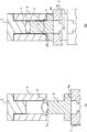
ここで、所定位置とは、下型2の上端が、胴型4の内周面に設けられた案内部22に接近した位置である。換言すれば、下型2の上端が胴型4の下端より内部に入り、かつ、案内部22のテーパ範囲内の高さにあるときである。案内部22のテーパは成形型のサイズ、形状によって異なるが、胴型4の下端部の内径が中央部の内径よりも1mm以上大きくなるように形成され、角度は胴型4の中心軸に対して45°以内が好ましく、より好ましくは30°以内である。また、成形面に影響を与えない範囲で、下型2の上端周縁にテーパを設けてもよい。
Here, the predetermined position is a position at which the upper end of the
下型2が所定位置に達した時点で、制御部10からの信号にもとづいて、下型2を載置台5に保持している真空吸着を解除する。そして、次に、エアシリンダ8を作動させて、下型2をさらに上昇(第二段階)させる。これにより、下型2の上端は胴型4の案内部22に沿ってガイドされ、図3(B)に示すように胴型4に嵌合する。
When the
このように、第一段階の上昇においては、下型2を載置台5に一体的に保持し、装置の振動などに起因して下型位置がずれることを防止することが効果的である一方、第二段階においては、下型2の上端がすでに胴型4の案内部22に入り込んでいるので、案内部22にガイドされながら下型2は上昇し、その後は胴型内周との摺動に案内されて胴型4に嵌挿される。このようにして組み立てることが、クリアランスの小さな成形型の組立において最も確実であることを、発明者らは見出した。
As described above, in the first stage of raising, it is effective to hold the
すなわち、第二段階では、下型2の中心軸線と胴型4の中心軸線との間にわずかな位置ずれや傾きがある場合(図3(B)二点鎖線の状態)においても、前述のように、下型2の上端部の周縁が胴型4の案内部22に部分的に接触してガイドされながら上昇する。その際、下型2は真空吸着されていないので、載置台5の上面7で移動しながら胴型4の中心軸線に対する下型2の中心軸線の位置ずれ及び多少の傾きを修正しながら胴型4内を上昇する。したがって、下型2は胴型4との間に大きな抵抗を生じることなく、成形型の組立状態の位置までスムーズに上昇し、嵌合される。
That is, in the second stage, even when there is a slight misalignment or inclination between the center axis of the
このように嵌合が許容されるためには、下型2の中心軸線と胴型4の中心軸線との間のずれや傾きはごくわずかしか許容されず、このために、第一段階における下型2の上昇においては、ずれや傾きが生じないよう載置台5に下型2が一体的に保持されている必要がある。一方、下型の嵌合時には一体保持が解除され、下型2が、載置台5上で、移動できるようになっていることが有効なのである。
In order to allow the fitting in this way, a slight deviation or inclination between the center axis of the
第一段階における下型2の上昇は、高い精度で位置制御が可能なサーボモータ7を用いたが、第二段階においては、エアシリンダ8を用いることがきわめて有利である。すなわち、第二段階においては、下型2と胴型4の相互位置に、わずかなずれや傾きが生じた場合に、下型2は胴型4にスムーズに嵌合されず、胴型4との間に大きな抵抗を生じる。このとき、目標位置の設定により、必ず所定量だけ駆動するサーボモータなどを用いると、ある一定の位置に達するまでモータは回り続けるために、下型2が胴型4へ強固に噛み込み、型破損を生じることがある。しかしながら、このような場合であっても、エアシリンダを用いると、エアの緩衝作用によって、下型2の胴型4への噛み込みが緩和され型の破損に至らない。
エアシリンダ8のほかには、同様に、媒体の圧縮力によって駆動を行うオイルシリンダを用いることも可能であるが、圧縮力の大きさからすると、エアシリンダがより好ましい。
For raising the
In addition to the
下型2が上端位置(分解前の位置)まで上昇した後、エアシリンダ8を停止する。このとき、成形素材Pの高さが成形されるガラス成形体Sの肉厚より高いため、上型3はその分若干押し上げられる。
After the
なお、エアシリンダ8による下型2の上昇速度は、サーボモータ7の上昇速度より遅くすることが好ましい。すなわち、成形型の組立作業を速く行うためには、下型2の昇降を速く行う必要がある。しかし、下型2を胴型4に嵌合する場合には、前述したように、下型2を移動させながら案内部22でガイドしながら胴型4に嵌合させなければならないことがある。このような場合には、下型2の移動を円滑に行わせるには、上昇速度をある程度ゆっくりさせる必要があるからである。
In addition, it is preferable that the rising speed of the
次に、押圧手段16のシリンダ19を作動させてピストンロッド19aを後退させて、挟持体18を胴型4から離すことにより、成形型1はフリーの状態になり、組立て作業が終了する。
以後、前述した、図示しない成形型の搬送装置により、成形型1の下型2の最外側面がチャックされ、ガラス成形体のプレス成形装置の取出し挿入室に搬送され、成形のための各種処理が施される。
Next, the
Thereafter, the outermost surface of the
なお、下型2を昇降させる第1及び第2の駆動手段の切替位置は、エアシリンダの所定の移動量に基づいてあらかじめ制御部に入力しておくことにより制御してもよく、あるいは、下型2又は載置台5の位置を、検知手段によって検知し、その検知信号によって制御してもよい。
The switching position of the first and second driving means for raising and lowering the
成形型の分解に際しては、特に、二段階の下型下降を行う必要は無いが、組立時と同様に二段階に切り替えて行ってもよい。すなわち、真空吸着により下型を載置台に一体的に保持した状態で、下型を第2の駆動手段によって下降させ、前記所定位置と同一の位置に達したところで、第1の駆動手段に切替えてさらに下降させてもよい。
また、エアシリンダからサーボモータへの駆動の切り替えは必須ではなく、成形体Sの取り出し位置まで単一の手段で降下させてもよい。
When disassembling the mold, it is not particularly necessary to lower the lower mold in two stages, but it may be performed in two stages as in the assembly. That is, the lower die is lowered by the second driving means while the lower die is integrally held on the mounting table by vacuum suction, and when it reaches the same position as the predetermined position, it is switched to the first driving means. May be further lowered.
Further, switching of the drive from the air cylinder to the servo motor is not essential, and it may be lowered by a single means to the take-out position of the molded body S.
上記の成形型の組立装置は、成形型に載置した成形素材を加熱して軟化させた後プレス成形して成形体を製造するモールドプレス成形装置に組み込んで利用することができる。また、成形型の組立方法は、前記成形型に対する成形素材の充填を行い、かつ、前記下型に載置され加熱により軟化した成形素材をプレス成形することによって成形体を製造する成形体の製造方法における一工程として利用することができる。 The mold assembly apparatus described above can be used by being incorporated into a mold press molding apparatus that heats and softens a molding material placed on the mold and then press-molds to produce a molded body. In addition, the method for assembling the molding die includes the production of a molded body by filling the molding die with a molding material and press-molding the molding material placed on the lower die and softened by heating. It can be used as a step in the method.
本発明は、所望の光学素子形状にもとづいて精密加工され、高精度ガラスレンズなどの光学素子をプレス成形するモールドプレス成形型を組み立てるときに有効に利用することができる。また、このモールドプレス成形型を用いた光学素子を製造するときに適用される。 INDUSTRIAL APPLICABILITY The present invention can be effectively used when assembling a mold press mold that is precisely processed based on a desired optical element shape and press-molds an optical element such as a high-precision glass lens. Moreover, it applies when manufacturing the optical element using this mold press mold.
1 成形型
2 下型
3 上型
4 胴型
5 載置台
6 保持手段
7 第一駆動手段(サーボモータ)
7a ボールスクリュ
7b 検知手段
8 第二駆動手段(エアシリンダ)
10 制御手段
14 位置決め手段
16 押圧手段
22 案内部
DESCRIPTION OF
7a Ball screw 7b Detection means 8 Second drive means (air cylinder)
DESCRIPTION OF
Claims (11)
前記胴型を固定する固定手段と、
前記下型を載置する載置台と、
この載置台に載置された下型を保持する保持手段と、
前記載置台を昇降させる昇降手段と、
前記載置台の上昇により、前記下型が前記胴型と接近した所定位置に達したことを検知する検知手段と、
前記昇降手段の駆動を制御するとともに、前記検知手段による前記所定位置の検知にもとづいて、前記保持手段の保持を解除して前記下型を移動可能とする制御手段を
備えたことを特徴する成形型の組立装置。 In a mold assembly apparatus for assembling a mold having an upper mold, a lower mold, and a body mold,
Fixing means for fixing the body mold;
A mounting table for mounting the lower mold;
Holding means for holding the lower mold placed on the placing table;
Elevating means for elevating and lowering the mounting table;
Detecting means for detecting that the lower mold has reached a predetermined position close to the body mold by raising the mounting table;
Molding comprising: control means for controlling the driving of the elevating means and releasing the holding of the holding means based on detection of the predetermined position by the detecting means so that the lower mold can be moved. Mold assembly equipment.
成形素材を前記成形面に配置した前記下型を載置台に保持する工程と、
前記載置台を上昇させることにより、前記下型が前記胴型の案内部に接近したとき、前記下型の保持を解除して移動可能とする工程と、
前記載置台をさらに上昇させ、移動可能となった前記下型を前記案内部によってガイドしながら前記胴型の内部に嵌合する工程を
有することを特徴とした成形型の組立方法。 In an assembling method of a molding die for assembling a molding die including an upper die and a lower die having opposite molding surfaces, and a body die having a tapered guide portion formed on the inner periphery of the opening on the lower die side,
Holding the lower mold with the molding material placed on the molding surface on a mounting table;
By raising the mounting table, when the lower mold approaches the guide part of the trunk mold, releasing the holding of the lower mold and making it movable;
A method for assembling a molding die, comprising the step of further raising the mounting table and fitting the movable lower die while guiding the lower die with the guide portion.
Priority Applications (1)
| Application Number | Priority Date | Filing Date | Title |
|---|---|---|---|
| JP2004219237A JP4485874B2 (en) | 2004-07-27 | 2004-07-27 | Mold assembly apparatus, mold press molding apparatus, mold assembly method, and molded body manufacturing method |
Applications Claiming Priority (1)
| Application Number | Priority Date | Filing Date | Title |
|---|---|---|---|
| JP2004219237A JP4485874B2 (en) | 2004-07-27 | 2004-07-27 | Mold assembly apparatus, mold press molding apparatus, mold assembly method, and molded body manufacturing method |
Publications (3)
| Publication Number | Publication Date |
|---|---|
| JP2006036592A JP2006036592A (en) | 2006-02-09 |
| JP2006036592A5 JP2006036592A5 (en) | 2007-07-12 |
| JP4485874B2 true JP4485874B2 (en) | 2010-06-23 |
Family
ID=35901979
Family Applications (1)
| Application Number | Title | Priority Date | Filing Date |
|---|---|---|---|
| JP2004219237A Expired - Lifetime JP4485874B2 (en) | 2004-07-27 | 2004-07-27 | Mold assembly apparatus, mold press molding apparatus, mold assembly method, and molded body manufacturing method |
Country Status (1)
| Country | Link |
|---|---|
| JP (1) | JP4485874B2 (en) |
Families Citing this family (4)
| Publication number | Priority date | Publication date | Assignee | Title |
|---|---|---|---|---|
| JP4946510B2 (en) * | 2007-02-28 | 2012-06-06 | コニカミノルタオプト株式会社 | Manufacturing method of glass substrate and manufacturing method of information recording medium |
| JP2017091597A (en) * | 2015-11-17 | 2017-05-25 | シャープ株式会社 | Optical product assembly device |
| JP7103977B2 (en) * | 2019-03-04 | 2022-07-20 | Hoya株式会社 | Press molding equipment |
| JP7309645B2 (en) * | 2020-03-23 | 2023-07-18 | 芝浦機械株式会社 | Glass forming machine and conveying device for conveyed object |
Citations (1)
| Publication number | Priority date | Publication date | Assignee | Title |
|---|---|---|---|---|
| JP2665018B2 (en) * | 1990-03-30 | 1997-10-22 | ホーヤ株式会社 | Mold disassembly / assembly equipment |
-
2004
- 2004-07-27 JP JP2004219237A patent/JP4485874B2/en not_active Expired - Lifetime
Patent Citations (1)
| Publication number | Priority date | Publication date | Assignee | Title |
|---|---|---|---|---|
| JP2665018B2 (en) * | 1990-03-30 | 1997-10-22 | ホーヤ株式会社 | Mold disassembly / assembly equipment |
Also Published As
| Publication number | Publication date |
|---|---|
| JP2006036592A (en) | 2006-02-09 |
Similar Documents
| Publication | Publication Date | Title |
|---|---|---|
| JPH0524857A (en) | Press-forming of optical element | |
| JP4780982B2 (en) | Mold press molding apparatus and optical element manufacturing method | |
| JP4718864B2 (en) | Press mold and press molding method | |
| JP2000044255A (en) | Transfer device for optical glass blank | |
| JP4485874B2 (en) | Mold assembly apparatus, mold press molding apparatus, mold assembly method, and molded body manufacturing method | |
| JP4667931B2 (en) | Mold press apparatus and mold press molded product manufacturing method | |
| JP2665018B2 (en) | Mold disassembly / assembly equipment | |
| KR20090082369A (en) | Optical element pressing apparatus | |
| US7293430B2 (en) | Press molding apparatus and press molding method of optical element | |
| JP2008001568A (en) | Glass molding apparatus and glass molding method | |
| JP7158928B2 (en) | Forming mold disassembly and assembly device and forming device | |
| JP7158925B2 (en) | Forming mold disassembly and assembly equipment | |
| JPS60124224A (en) | Press molding method and device for thermoplastic material product | |
| JP4366179B2 (en) | Glass forming apparatus and method | |
| KR101165475B1 (en) | Cast molding assembling apparatus and manufacturing method for optical element | |
| JP7103977B2 (en) | Press molding equipment | |
| JP2006273661A (en) | Glass molding apparatus, tool for holding glass blank and glass molding method | |
| JP4382529B2 (en) | Mold press molding apparatus and optical element manufacturing method | |
| JP2005281053A (en) | Forming apparatus for mold press, method of manufacturing optical device, and optical device | |
| JP5106792B2 (en) | Method and apparatus for forming cylindrical container | |
| KR102169007B1 (en) | Contact lens manufacturing apparatus | |
| JP3897746B2 (en) | Press molded body suction device, suction method, and optical element manufacturing method using the same | |
| JP2669479B2 (en) | Optical element molding die and method for adjusting the same | |
| JP2007131467A (en) | Optical element molding apparatus | |
| JP2636083B2 (en) | Optical element molding method |
Legal Events
| Date | Code | Title | Description |
|---|---|---|---|
| A521 | Request for written amendment filed |
Free format text: JAPANESE INTERMEDIATE CODE: A523 Effective date: 20070530 |
|
| A621 | Written request for application examination |
Free format text: JAPANESE INTERMEDIATE CODE: A621 Effective date: 20070530 |
|
| A977 | Report on retrieval |
Free format text: JAPANESE INTERMEDIATE CODE: A971007 Effective date: 20091022 |
|
| A131 | Notification of reasons for refusal |
Free format text: JAPANESE INTERMEDIATE CODE: A131 Effective date: 20091201 |
|
| TRDD | Decision of grant or rejection written | ||
| A01 | Written decision to grant a patent or to grant a registration (utility model) |
Free format text: JAPANESE INTERMEDIATE CODE: A01 Effective date: 20100323 |
|
| A01 | Written decision to grant a patent or to grant a registration (utility model) |
Free format text: JAPANESE INTERMEDIATE CODE: A01 |
|
| A61 | First payment of annual fees (during grant procedure) |
Free format text: JAPANESE INTERMEDIATE CODE: A61 Effective date: 20100325 |
|
| R150 | Certificate of patent or registration of utility model |
Ref document number: 4485874 Country of ref document: JP Free format text: JAPANESE INTERMEDIATE CODE: R150 Free format text: JAPANESE INTERMEDIATE CODE: R150 |
|
| FPAY | Renewal fee payment (event date is renewal date of database) |
Free format text: PAYMENT UNTIL: 20130402 Year of fee payment: 3 |
|
| FPAY | Renewal fee payment (event date is renewal date of database) |
Free format text: PAYMENT UNTIL: 20130402 Year of fee payment: 3 |
|
| FPAY | Renewal fee payment (event date is renewal date of database) |
Free format text: PAYMENT UNTIL: 20140402 Year of fee payment: 4 |
|
| R250 | Receipt of annual fees |
Free format text: JAPANESE INTERMEDIATE CODE: R250 |
|
| R250 | Receipt of annual fees |
Free format text: JAPANESE INTERMEDIATE CODE: R250 |
|
| R250 | Receipt of annual fees |
Free format text: JAPANESE INTERMEDIATE CODE: R250 |
|
| R250 | Receipt of annual fees |
Free format text: JAPANESE INTERMEDIATE CODE: R250 |
|
| R250 | Receipt of annual fees |
Free format text: JAPANESE INTERMEDIATE CODE: R250 |
|
| R250 | Receipt of annual fees |
Free format text: JAPANESE INTERMEDIATE CODE: R250 |
|
| R250 | Receipt of annual fees |
Free format text: JAPANESE INTERMEDIATE CODE: R250 |
|
| R250 | Receipt of annual fees |
Free format text: JAPANESE INTERMEDIATE CODE: R250 |