JP4485362B2 - Herringbone gear teeth and manufacturing method thereof - Google Patents
Herringbone gear teeth and manufacturing method thereof Download PDFInfo
- Publication number
- JP4485362B2 JP4485362B2 JP2004527987A JP2004527987A JP4485362B2 JP 4485362 B2 JP4485362 B2 JP 4485362B2 JP 2004527987 A JP2004527987 A JP 2004527987A JP 2004527987 A JP2004527987 A JP 2004527987A JP 4485362 B2 JP4485362 B2 JP 4485362B2
- Authority
- JP
- Japan
- Prior art keywords
- manufacturing
- cutter
- gear
- relief
- gear teeth
- Prior art date
- Legal status (The legal status is an assumption and is not a legal conclusion. Google has not performed a legal analysis and makes no representation as to the accuracy of the status listed.)
- Expired - Lifetime
Links
- 238000004519 manufacturing process Methods 0.000 title claims abstract description 24
- 150000004767 nitrides Chemical class 0.000 claims abstract description 5
- 238000000034 method Methods 0.000 claims description 12
- 239000002994 raw material Substances 0.000 claims description 11
- 238000005255 carburizing Methods 0.000 claims description 8
- 238000011282 treatment Methods 0.000 claims description 3
- 238000010791 quenching Methods 0.000 claims 4
- 230000000171 quenching effect Effects 0.000 claims 4
- 239000000463 material Substances 0.000 abstract description 3
- 229910000760 Hardened steel Inorganic materials 0.000 description 5
- 238000005520 cutting process Methods 0.000 description 5
- 238000003754 machining Methods 0.000 description 5
- 238000007730 finishing process Methods 0.000 description 4
- 229910000831 Steel Inorganic materials 0.000 description 3
- 230000005540 biological transmission Effects 0.000 description 3
- 239000010959 steel Substances 0.000 description 3
- 230000001154 acute effect Effects 0.000 description 2
- 238000005452 bending Methods 0.000 description 2
- 238000003801 milling Methods 0.000 description 2
- 238000005121 nitriding Methods 0.000 description 2
- 230000015572 biosynthetic process Effects 0.000 description 1
- 238000005260 corrosion Methods 0.000 description 1
- 230000007797 corrosion Effects 0.000 description 1
- 230000007774 longterm Effects 0.000 description 1
- 230000000873 masking effect Effects 0.000 description 1
- 239000000155 melt Substances 0.000 description 1
- 229910052751 metal Inorganic materials 0.000 description 1
- 239000002184 metal Substances 0.000 description 1
- 150000002739 metals Chemical class 0.000 description 1
- 238000012986 modification Methods 0.000 description 1
- 230000004048 modification Effects 0.000 description 1
- 230000000704 physical effect Effects 0.000 description 1
Images


Classifications
-
- B—PERFORMING OPERATIONS; TRANSPORTING
- B23—MACHINE TOOLS; METAL-WORKING NOT OTHERWISE PROVIDED FOR
- B23P—METAL-WORKING NOT OTHERWISE PROVIDED FOR; COMBINED OPERATIONS; UNIVERSAL MACHINE TOOLS
- B23P15/00—Making specific metal objects by operations not covered by a single other subclass or a group in this subclass
- B23P15/14—Making specific metal objects by operations not covered by a single other subclass or a group in this subclass gear parts, e.g. gear wheels
-
- B—PERFORMING OPERATIONS; TRANSPORTING
- B23—MACHINE TOOLS; METAL-WORKING NOT OTHERWISE PROVIDED FOR
- B23F—MAKING GEARS OR TOOTHED RACKS
- B23F7/00—Making herringbone gear teeth
-
- Y—GENERAL TAGGING OF NEW TECHNOLOGICAL DEVELOPMENTS; GENERAL TAGGING OF CROSS-SECTIONAL TECHNOLOGIES SPANNING OVER SEVERAL SECTIONS OF THE IPC; TECHNICAL SUBJECTS COVERED BY FORMER USPC CROSS-REFERENCE ART COLLECTIONS [XRACs] AND DIGESTS
- Y10—TECHNICAL SUBJECTS COVERED BY FORMER USPC
- Y10T—TECHNICAL SUBJECTS COVERED BY FORMER US CLASSIFICATION
- Y10T29/00—Metal working
- Y10T29/49—Method of mechanical manufacture
- Y10T29/49462—Gear making
- Y10T29/49467—Gear shaping
- Y10T29/49476—Gear tooth cutting
-
- Y—GENERAL TAGGING OF NEW TECHNOLOGICAL DEVELOPMENTS; GENERAL TAGGING OF CROSS-SECTIONAL TECHNOLOGIES SPANNING OVER SEVERAL SECTIONS OF THE IPC; TECHNICAL SUBJECTS COVERED BY FORMER USPC CROSS-REFERENCE ART COLLECTIONS [XRACs] AND DIGESTS
- Y10—TECHNICAL SUBJECTS COVERED BY FORMER USPC
- Y10T—TECHNICAL SUBJECTS COVERED BY FORMER US CLASSIFICATION
- Y10T74/00—Machine element or mechanism
- Y10T74/19—Gearing
- Y10T74/19949—Teeth
- Y10T74/19953—Worm and helical
Abstract
Description
本発明は一般にギヤ歯に関し、特に、ヘリングボーンギヤ歯及びその改良された製造方法に関する。 The present invention relates generally to gear teeth, and more particularly to herringbone gear teeth and improved manufacturing methods thereof.
はすば歯車(これは軸に対して鋭角に切削された歯を有する)は、回転のすべての点でかみ合う多数の歯を有し、圧力を各歯の全長に沿って均等に分配するように設計される。 Helical gears (which have teeth cut at an acute angle to the axis) have a number of teeth that engage at all points of rotation so that pressure is evenly distributed along the entire length of each tooth. Designed to.
したがって、この歯車は滑らかな作動と信頼性を提供し、動力の伝達に関して理想的である。単はすば歯車(これは、また、ねじれ平歯車と呼ばれる)の歯の角度のために、軸方向スラストが生成されるが、2つの対向するらせんを使用することによって、誘発された軸スラストは除去される。 Therefore, this gear offers smooth operation and reliability and is ideal for power transmission. An axial thrust is generated due to the angle of the teeth of a single helical gear (also called a helical spur gear), but the axial thrust induced by using two opposing spirals Is removed.
精密歯車の性能は主として歯の精度と表面特性で決定される。多くの場合、歯車の表面は浸炭、窒化又は同様の処理によって堅くされ、その後、機械加工されつや出しされる。表面硬化処理(はだ焼き)は摩耗と耐蝕性を改良し、表面の均一性と純度を高め、残留圧縮応力を生じさせて歯車の性能と寿命を顕著に改良することになる。その上、表面硬化された鋼の物理特性は非常に良く、通し焼入れ鋼ギヤとして2倍のトルクを伝えることができる。 The performance of precision gears is mainly determined by tooth accuracy and surface characteristics. In many cases, the surface of the gear is hardened by carburizing, nitriding or similar treatment, and then machined and polished. Surface hardening treatments (adducts) improve wear and corrosion resistance, increase surface uniformity and purity, and cause residual compressive stress to significantly improve gear performance and life. In addition, the physical properties of surface hardened steel are very good and can transmit twice as much torque as a through-hardened steel gear.
やまば歯車を一般に2つのタイプに分類することができる。即ち、図1に示されるように2つのらせんが中央で合い連続した歯を形成するヘリングボーン歯車(ギヤ)と、図2に示されるように2つのらせんの間にリリーフギャップを有する従来のやまば歯車である。 Spiral gears can generally be classified into two types. That is, a herringbone gear (gear) in which two spirals meet at the center to form a continuous tooth as shown in FIG. 1 and a conventional mountain having a relief gap between the two spirals as shown in FIG. It is a gear.
ヘリングボーン歯車(図1)は、ポンプローター、及び、低速高トルクを必要とする伝動歯車、特に伝動歯車の歯幅が限定される歯車として使用される。連続ばりのやまば歯車伝動装置は50年間以上に渡り使用されているが、頂部で歯を機械加工することの製造の難しさにより、歯の一部を硬化させること、及び歯の寸法精度のよくすることには限度があった。ヘリングボーン歯車は、2つの対向する螺旋を各マシン打撃により左側の螺旋、次に右側の螺旋を交互に切削する複数の往復動カッターにより同時に機械加工するサイクス(Sykes)歯車形成機又はシェーパーで形成するように制限される。これらのカッターは歯車の面の中心へストローク移動するときに歯の形状に切削する。この処理の制限は大ピッチ高精度サイクスカッターの不足である。さらに、これらのカッターが35ロックウェルCを超える硬度の金属を切ることができないので、仕上げ処理は通し焼入れ鋼ギヤに制限される。歯の仕上げ処理は等しく不正確であり統計的な予測ができない。 Herringbone gears (FIG. 1) are used as pump rotors and transmission gears that require low speed and high torque, especially gears with limited tooth widths. Continuous beam spur gear transmissions have been in use for over 50 years, but due to the difficulty of manufacturing teeth machining at the top, it is possible to harden part of the teeth and improve the dimensional accuracy of the teeth. There was a limit to what we could do well. Herringbone gears are formed by a Sykes gear former or shaper that simultaneously machines two opposing spirals by multiple reciprocating cutters that alternately cut the left spiral by each machine strike and then the right spiral. To be limited. These cutters cut into a tooth shape as they move to the center of the gear face. The limitation of this process is the shortage of large pitch high precision squeak cutter. Furthermore, since these cutters cannot cut metals with hardness above 35 Rockwell C, the finishing process is limited to through-hardened steel gears. The tooth finishing process is equally inaccurate and cannot be statistically predicted.
反対に、図2で示される従来のやまば歯車はヘリングボーン歯車の制限を受けない。リリーフギヤップはカッター中心線が螺旋の端部を超えることを許容するので、これらの歯車を切って仕上げるために、58ロックウェルCよりもはるかに硬い硬化鋼を旋削できるものを含めたさまざまな高精度工作ツールを使用することができる。したがって、リリーフギヤップを有する従来のやまば歯車はヘリングボーン歯車よりも高い性能を必要とする場合に、より一般に使用される。 Conversely, the conventional spur gear shown in FIG. 2 is not limited by the herringbone gear. Relief gearups allow the cutter centerline to extend beyond the end of the helix, so various gears, including those that can turn hardened steel much harder than 58 Rockwell C to cut and finish these gears. A precision tool can be used. Thus, conventional blind gears with relief gears are more commonly used when they require higher performance than herringbone gears.
ポンプに使用する場合、あいにく、リリーフギヤップを備える歯車をポンプローターとして使用することは不適当であるので、硬度と表面硬化厚が制限されたヘリングボーン歯を使用しなければならない。通常、これらの歯車に仕上げの切削がなされ、次に窒化されて、0.508mm乃至0.635mm(0.020インチ乃至0.025インチ)の表面硬化が付与される。窒化は高温で行われるため、ひずみにより表面に不揃いが生じる。この短所はポンプ性能に直接影響する。例えば、塑性プラスチックの溶融ポンプに使用されるヘリングボーン歯車は、浅い焼き肌深さ、オーバロード圧又は旋削で生じうる歯の誤差のために歯面に表面硬化剥離を生じることがありえる。改良された硬度及び歯の品質を有するヘリングボーン歯車が望まれている。 Unfortunately, when used in pumps, it is inappropriate to use gears with relief gears as pump rotors, so herringbone teeth with limited hardness and hardened surface thickness must be used. Typically, these gears are finished cut and then nitrided to give a surface hardening of 0.050 mm to 0.635 mm (0.020 inch to 0.025 inch). Since nitriding is performed at a high temperature, the surface is uneven due to strain. This disadvantage directly affects pump performance. For example, herringbone gears used in the melt pump plastic plastic, shallow baked skin depth, overload pressure or Ru example can cause surface hardening peeling the tooth surface for error teeth may occur in turning. Herringbone gears with improved hardness and tooth quality are desired.
発明の目的
発明の第一の目的は、円柱原材料から始まって、歯車の表面を横切る連続ばりを形成し、次に歯車を浸炭し、それに仕上げ加工を施して図2の従来のギャップを備える浸炭やまば歯車の高精度の特性をもたらすようにすることにより、図1の形態のやまばヘリングボーン歯車を提供することである。
Object of the Invention The first object of the invention is to start with a cylindrical raw material, form a continuous beam across the surface of the gear, then carburize the gear, then finish it to carburize with the conventional gap of FIG. By providing the high accuracy characteristics of the splint gear, it is to provide a spurious herringbone gear of the form of FIG.
発明の別の目的は、プラスチック溶融ポンプ用ローターとして使用するために特に製造される歯車であって、58−62ロックウェルC硬度になるように熱処理され、1つ以上のより正確なギヤ製造カッターによってアメリカギヤメーカー協会(AGMA)品質に従う以前の連続ばり歯よりほぼ6倍正確な歯に仕上げられる歯車を製造する方法を提供することである。 Another object of the invention is a gear manufactured specifically for use as a rotor for a plastic melt pump, heat treated to 58-62 Rockwell C hardness, and one or more more accurate gear manufacturing cutters. Is to provide a method of manufacturing gears that are finished to a tooth that is almost six times more accurate than previous continuous spur teeth according to American Gear Manufacturers Association (AGMA) quality.
上記目的及び他の特徴と利点は、円柱原材料から始まるヘリングボーン歯車を製造する方法において提供される。円柱原材料において2つの螺旋が合うところに各歯のリリーフノッチが確立される。次に、二重螺旋状の歯(やまば歯車)が粗形成され、歯車は表面硬化を施される。浸炭法を使用することによって、0.508mm乃至0.635mm(0.200乃至0.025インチ)のより深い表面硬化を得ることができる。歯は、次に、高精度の立方体ボルゾン窒化物(Cubic Borzon Nitride:CBN)面を備えるカッターを使用して該カッターの振れを許容するリリーフノッチを備えるものとして仕上げられる。 The above objects and other features and advantages are provided in a method of manufacturing a herringbone gear starting from a cylindrical raw material. A relief notch for each tooth is established where the two spirals meet in the cylindrical raw material. Next, double helical teeth (coiled gears) are roughly formed, and the gears are surface hardened. By using the carburizing method, a deeper surface hardening of 0.508 mm to 0.635 mm (0.200 to 0.025 inches) can be obtained. The teeth are then finished using a cutter with a high precision Cubic Borzon Nitride (CBN) surface, with relief notches that allow the cutter to swing.
添付図面に概略的に示す実施の形態に基づいて発明を以下に詳細に説明する。 The invention will be described in detail below on the basis of an embodiment schematically shown in the accompanying drawings.
図3を参照して、発明に従った方法は硬化されていない高品質の鋼原材料10を機械加工して歯車部品としての円柱形を形成することに始まる。次に、歯車の各歯13に一連のリリーフノッチ12が機械加工される。リリーフノッチ12はその後の仕上げ処理におけるツール振れを許容する。サイクスカット(Sykesカット)ヘリングボーン歯車は歯車形成機の切削動作から形成された2つの螺旋の鋭角交点においてわずかな溝を有するが、この溝は本発明の仕上げ加工のための十分なクリアランスを提供しない。
Referring to FIG. 3, the method according to the invention begins with machining a high quality steel
リリーフノッチ12は、機械加工により、部分10の円周の周りで各2つの隣接する歯13の間の頂部14(ここで2つの螺旋が合う)において一連のインボリュートカットとして作られる。リリーフノッチ12は初めに、歯車表面のセンター、即ち頂部14に機械加工される。この部分10は所定量だけ回転され、フライス削りヘッド15が軸方向にある量だけ割り出され、歯のねじれ角を繰り返して付ける。フライス削りヘッド15は、次に、面のセンターライン14の反対側の点に動かされて同様のツール経路を機械加工する。ここでもその部分は回転され、さらに2つのツール経路が歯車表面のセンターライン14から次第に遠くなる位置で機械加工される。この処理は適切な1つのリリーフノッチ12が形成されるまで繰り返される。リリーフノッチ12は、ギヤ歯の内角17にツールが必要に振れて入ることを許す。図3が示すように、最初にすべてリリーフノッチ12を形成し、その後にギヤ歯を粗形成してもよいし、あるいは、1つのリリーフノッチ12を機械加工したすぐ後に、その対応する歯13を粗形成することとしてもよい。
The
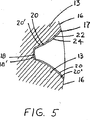
図4と5は各リリーフノッチ12の形状とプロフィールについて説明する。リリーフノッチ12は、2つの隣接する歯13のトップランド(top lands)16間の頂部14に位置される。両方の螺旋のボトムランド(Bottom lands)18と各歯面20を示す。リリーフノッチ12はインボリュート歯プロフィール24と同様であるが、わずかに大きくかつ深いプロフィール22を有する。ノッチ底ランド18’と表面20’が示されている。
4 and 5 illustrate the shape and profile of each
リリーフノッチプロフィール22は仕上げられた歯のプロフィール24よりもわずかに大きいので、後の仕上げ処理の間に、仕上げカッターがリリーフ12内にストローク移動するとき、原材料を削ることない。
The relief notch profile 22 is slightly larger than the finished tooth profile 24 so that during the subsequent finishing process, the raw material is not scraped as the finishing cutter is stroked into the
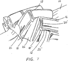
図6に示すように、ギヤ歯の粗形成はミル(製作機械)を使用してなされ、階段の段に似たギヤ歯インボリュートプロフィールとされる。次に、階段の段の体裁は、マアーグ(Maag)カッター及び/又はラックタイプの粗形成シェーパーカッターによって取り除かれ、図7に示すように、必要な仕上げプロフィール24(図5参照)の約0.508mm(約0.020インチ)内側の滑らかなギヤ歯をもたらす。 As shown in FIG. 6, the rough formation of the gear teeth is performed using a mill (manufacturing machine), resulting in a gear tooth involute profile resembling a stair step. Next, the appearance of the stair steps is removed by a Maag cutter and / or a rack-type rough forming shaper cutter, as shown in FIG. 508mm (about 0.020 inch) inner smooth gear teeth are provided.
ヘリングボーン歯車は粗形成された後に約58−62ロックウェルCの表面硬度に浸炭される。適した方法は2段階浸炭処理を使用することである。ギヤ歯13は最初に浸炭され掃除される。次に、ギヤ歯13とジャーナル(軸くび)26の両方が浸炭雰囲気にさらされる。最小焼き肌深さは歯の領域で5.08mm乃至7.62mm(0.200〜0.300インチ)、支承ジャーナル領域で、1.06mm(0.040インチ)であるべきである。これは浸炭サイクルの一部の間に支承ジャーナルをマスキングすることによって達成される。
Herringbone gears are coarsely formed and then carburized to a surface hardness of about 58-62 Rockwell C. A suitable method is to use a two-stage carburizing process. The
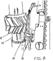
浸炭の後に、図8で示されるように、その部分は、立方体ボルゾン窒化物(Cubic Borzon Nitride:CBN)の面を有する高精度往復差し込みカッター30を使用して仕上げられる。歴史的に、この仕上げ技術は、ツール振れのために、螺旋間で約25.4mm(約1インチ)幅のギヤップを必要とするが、特別なカッター30を使用することによって、このツール振れは最小にされる。また、CBNカッター30はレーキ角低減のための特殊ツールポスト32によって保持される。原材料10が回転割り出しされ、一方、カッター30は歯車を削って、表面硬化された材料を約0.508mm(約0.020インチ)取り除く。リリーフノッチ12はカッター30の振れを許容し、ノッチ12内の材料はカッター30によって取り除かれない。上で説明したように、リリーフノッチ12は歯13間に機械加工されるので、2つの螺旋が接合され、仕上げツールの振れのために必要なクリアランスをまだ残すことができる。
After carburization, the part is finished using a high
CBN刃タイプのカッター30は例外的な仕上げを提供し、長期間の摩耗が可能であり、切削力を減少させ、かつ、容易に利用可能である。さらに、カッター30の平坦な切断面とマアーグ(Maag)歯切りカッターの運動学のためにインボリュートが形成され、歯車インボリュート精度は割り出しやツール精度に依存しない。
The CBN
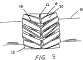
図9は、発明に従って製造されたヘリングボーン歯車(ギヤ)を示す。上で説明された方法は、ヘリングボーンギヤ歯が硬化され、かつ、改良されたCBNカッターを備えたより近代的なツールによって形成されるので、ヘリングボーンギヤ歯をより高精度に機械加工することができる。歯の精度は、硬化されたツールで歯を仕上げることによって大いに高められる。従来技術の機械加工により比較的軟質の鋼を加工した場合、0.609mm(0.0024インチ)以内のプロフィール精度が提供され、ねじれ角は0.004度以内(0.101mm(0.008インチ)のリード変動)である。発明を使用するとき、達成可能な歯の寸法精度は約10倍良く、プロフィール誤差は0.01254mm(0.00026インチ)未満であり、リード変動は0.01117mm(0.00044インチ)である。さらに、歯の精度を犠牲にしないで、歯面仕上げは20〜24RMSに達することができる。さらに、この処理に従って製造された歯車は、浸炭歯車に関する許容接触圧と曲げ応力に関する増大されたAGMA荷重補正係数及び等級を満たす。特に、AGMAの「接触応力数(Contact Stress Number)」は225000psiに達することができ、「曲げ応力数(Bending Stress Number)」は65000psiに達することができる。 FIG. 9 shows a herringbone gear (gear) manufactured according to the invention. The method described above allows the herringbone gear teeth to be machined with higher precision since the herringbone gear teeth are hardened and formed by a more modern tool with an improved CBN cutter. it can. Teeth accuracy is greatly enhanced by finishing the teeth with a hardened tool. When machining relatively soft steel by prior art machining, profile accuracy within 0.0009 mm (0.0024 inches) is provided, and twist angles are within 0.004 degrees (0.008 inches). ) Lead fluctuation). When using the invention, the achievable tooth dimensional accuracy is about 10 times better, the profile error is less than 0.01254 mm and the lead variation is 0.01117 mm. Furthermore, the tooth surface finish can reach 20-24 RMS without sacrificing tooth accuracy. Furthermore, gears manufactured according to this process meet the increased AGMA load correction factor and grade for allowable contact pressure and bending stress for carburized gears. In particular, AGMA's “Contact Stress Number” can reach 225,000 psi and “Bending Stress Number” can reach 65000 psi.
その結果、この発明で生産されたヘリングボーン歯車の品質はリリーフギヤップを備える従来のやまば歯車のものと同等となった。発明はより高速かつより正確な製造のためのより近代的な工作機の使用を可能にする。 As a result, the quality of the herringbone gear produced in this invention is equivalent to that of a conventional spur gear with a relief gear. The invention allows the use of more modern machine tools for faster and more accurate manufacturing.
発明の好ましい実施の形態について詳細に説明したが、この実施の形態を変更、変形することが可能であることは当業者にとって明らかである。そのような変更と変形は、特許請求の範囲記載された発明の技術的思想及び範囲内にあることが明白に理解される。 Although the preferred embodiment of the invention has been described in detail, it will be apparent to those skilled in the art that the embodiment can be modified and modified. It is expressly understood that such changes and modifications are within the spirit and scope of the claimed invention.
Claims (16)
前記円柱形状の軸に垂直な円の円周の周りに複数のリリーフノッチ(12)を形成し;
複数のやまば歯車歯の各歯(13)を、該歯が前記複数のリリーフノッチの隣接する対の間の前記円周に沿う場所に頂部(14)が位置するように、前記原材料のねじれ角に沿って粗形成し;
次に、前記複数のやまば歯車歯を焼き入れし;
該焼き入れの後に、前記複数のやまば歯車歯の各歯をカッター(15)で仕上げプロフィール(24)に仕上げると共に;
前記複数のリリーフノッチは前記仕上げプロフィールよりも深いインボリュートプロフィールを有しており、前記カッターが当該仕上げの際に前記リリーフノッチ内にストローク移動するとき、前記原材料を削らないように構成されたヘリングボーンギヤ歯の製造方法。Forming a cylindrical shape in the raw material (10) ;
Forming a plurality of relief notches (12) around the circumference of a circle perpendicular to the cylindrical axis;
Each tooth (13) of the plurality of helical gear teeth is twisted with the raw material such that the top (14) is located at a location along the circumference between the adjacent pairs of the plurality of relief notches. Coarsely formed along the corners;
Next, quenching the plurality of helical gear teeth;
After the quenching, each tooth of the plurality of helical gear teeth is finished with a cutter (15) to a finished profile (24) ;
The plurality of relief notches have an involute profile deeper than the finish profile , and herringbone configured to not scrape the raw material when the cutter strokes into the relief notch during the finish. Manufacturing method of gear teeth.
Applications Claiming Priority (2)
| Application Number | Priority Date | Filing Date | Title |
|---|---|---|---|
| US40226602P | 2002-08-08 | 2002-08-08 | |
| PCT/US2003/025046 WO2004015308A1 (en) | 2002-08-08 | 2003-08-08 | Herringbone gear teeth and method for manufacturing same |
Publications (2)
| Publication Number | Publication Date |
|---|---|
| JP2005535844A JP2005535844A (en) | 2005-11-24 |
| JP4485362B2 true JP4485362B2 (en) | 2010-06-23 |
Family
ID=31715821
Family Applications (1)
| Application Number | Title | Priority Date | Filing Date |
|---|---|---|---|
| JP2004527987A Expired - Lifetime JP4485362B2 (en) | 2002-08-08 | 2003-08-08 | Herringbone gear teeth and manufacturing method thereof |
Country Status (8)
| Country | Link |
|---|---|
| US (1) | US6912786B2 (en) |
| EP (1) | EP1552191B1 (en) |
| JP (1) | JP4485362B2 (en) |
| AT (1) | ATE437716T1 (en) |
| AU (1) | AU2003255252A1 (en) |
| CA (1) | CA2495574C (en) |
| DE (1) | DE60328617D1 (en) |
| WO (1) | WO2004015308A1 (en) |
Families Citing this family (33)
| Publication number | Priority date | Publication date | Assignee | Title |
|---|---|---|---|---|
| US20040094234A1 (en) * | 2002-11-15 | 2004-05-20 | Curtis Machine Company, Inc. | Methods and apparatus for reducing the sound level of a gearbox |
| JP4381769B2 (en) * | 2003-10-15 | 2009-12-09 | 株式会社エンプラス | Gear train and image forming apparatus |
| US7854995B1 (en) * | 2004-07-14 | 2010-12-21 | Keystone Investment Corporation | High density dual helical gear |
| CN100431761C (en) * | 2006-03-30 | 2008-11-12 | 中国第一重型机械集团公司 | Double herringbone gear in-phase processing method |
| US20080120843A1 (en) * | 2006-11-06 | 2008-05-29 | Gm Global Technology Operations, Inc. | Method for manufacturing low distortion carburized gears |
| WO2008101291A1 (en) * | 2007-02-22 | 2008-08-28 | Bishop Innovation Limited | Rack and pinion steering gear |
| JP4919495B2 (en) * | 2007-03-23 | 2012-04-18 | 株式会社エンプラス | Resin toothbrush gear |
| CN100525977C (en) * | 2007-07-23 | 2009-08-12 | 重庆齿轮箱有限责任公司 | Processing method of high-accuracy herringbone gear without withdrawing groove hard tooth surface |
| US8133146B2 (en) * | 2009-04-14 | 2012-03-13 | Eaton Corporation | Gear train with split torque |
| DE102010041489A1 (en) * | 2010-09-27 | 2012-03-29 | Deckel Maho Pfronten Gmbh | A method for producing a gear having an arrow toothing and method and apparatus for generating control data for forming an arrow toothing on a workpiece |
| JP2012143821A (en) * | 2011-01-07 | 2012-08-02 | Aisin Seiki Co Ltd | Method for manufacturing gear |
| RU2446923C1 (en) * | 2011-02-28 | 2012-04-10 | Государственное образовательное учреждение высшего профессионального образования "Тульский государственный университет" (ТулГУ) | Spur gear finishing tool |
| US9387544B2 (en) | 2011-05-02 | 2016-07-12 | Fairfield Manufacturing Company, Inc. | Smilled spline apparatus and smilling process for manufacturing the smilled spline apparatus |
| TW201320833A (en) * | 2011-11-11 | 2013-05-16 | Schoeller Electronics Gmbh | Form piece for pressing into a printed circuit board |
| US9145956B2 (en) | 2013-01-25 | 2015-09-29 | Gustomsc Resources B.V. | Torque sharing drive and torque sharing process |
| US9186180B2 (en) | 2013-03-08 | 2015-11-17 | Stryker Trauma Sa | Rose gear for external fixation clamp |
| CN103331493B (en) * | 2013-07-11 | 2015-09-09 | 中信重工机械股份有限公司 | A kind of technique that can improve carburizing and quenching gear internal tooth tooth Profile Machining precision |
| US9531237B2 (en) | 2013-12-19 | 2016-12-27 | Gustomsc Resources B.V. | Dual rack output pinion drive |
| US9597743B2 (en) * | 2014-01-17 | 2017-03-21 | Sikorsky Aircraft Corporation | Machine for machining gear teeth and gear teeth machining method |
| GB201403413D0 (en) * | 2014-02-27 | 2014-04-16 | Rolls Royce Deutschland | A gearing arrangement |
| CN104353975B (en) * | 2014-06-11 | 2016-06-29 | 哈尔滨汽轮机厂有限责任公司 | A kind of processing method nitrogenizing gear |
| CN105033593A (en) * | 2014-11-27 | 2015-11-11 | 苏州晓谕精密机械股份有限公司 | Tooth bar high efficiency processing technology |
| CN104723046B (en) * | 2015-03-26 | 2017-04-12 | 西安北方光电科技防务有限公司 | Method for improving nitriding bevel gear wheel part machining precision |
| CN105127667A (en) * | 2015-07-01 | 2015-12-09 | 上海振华重工集团(南通)传动机械有限公司 | Knurling and press-fitting method for first-stage internal geared ring of cutter drive reduction gearbox |
| CN105234500A (en) * | 2015-11-13 | 2016-01-13 | 哈尔滨东安发动机(集团)有限公司 | Slotting method for herringbone gears with narrow clearance grooves |
| WO2017136263A1 (en) | 2016-02-03 | 2017-08-10 | Sikorsky Aircraft Corporation | Advanced herringbone gear design |
| CN105945534A (en) * | 2016-05-27 | 2016-09-21 | 苏州威富达精密机械制造有限公司 | Processing technique for intermediate spur gear |
| IT201600076227A1 (en) | 2016-07-20 | 2018-01-20 | Settima Meccanica S R L Soc A Socio Unico | Bi-helical gear wheel with variable helix angle and non-encapsulating tooth profile for gear hydraulic equipment |
| US10400678B2 (en) | 2017-01-03 | 2019-09-03 | General Electric Company | Apparatus and system for light-weight, flexible double-helical gear |
| DE102017011276A1 (en) | 2017-12-07 | 2019-06-13 | Rolls-Royce Deutschland Ltd & Co Kg | Method for producing a gear |
| CN111069714B (en) * | 2019-12-30 | 2021-05-11 | 綦江齿轮传动有限公司 | Method for aligning gear hobbing of intermediate shaft |
| CN111687495B (en) * | 2020-05-25 | 2022-04-22 | 西安交通大学 | Stepped feed rough cutting method for herringbone gear with narrow clearance groove |
| CN117340364B (en) * | 2023-12-04 | 2024-03-22 | 常州市泰博精创机械有限公司 | Gear machining device and method |
Family Cites Families (14)
| Publication number | Priority date | Publication date | Assignee | Title |
|---|---|---|---|---|
| US1443837A (en) * | 1920-01-10 | 1923-01-30 | Newark Gearcutting Machine Co | Sinusoidal gearing |
| US1480910A (en) * | 1920-02-26 | 1924-01-15 | Leerberg Nis | Machine for forming helical gears |
| US1496221A (en) * | 1922-01-23 | 1924-06-03 | Gleason Works | Method and apparatus for cutting herringbone gears |
| US1490457A (en) * | 1922-03-11 | 1924-04-15 | Eberhardt Ulrich Seth | Method of and hob for cutting gears |
| US2257989A (en) * | 1939-02-07 | 1941-10-07 | Sykes William Edwin | Gear lapping machine |
| US3531976A (en) * | 1967-11-27 | 1970-10-06 | Ford Motor Co | Cold rolling of fine pitch herringbone gears |
| US3891474A (en) | 1972-01-03 | 1975-06-24 | United States Steel Corp | Method for the case carburizing of steel |
| DE2607636C3 (en) * | 1976-02-25 | 1985-03-14 | Zahnräderfabrik Renk AG, 8900 Augsburg | Spur gear with single helical gears |
| JPS61161465U (en) * | 1985-03-29 | 1986-10-06 | ||
| US6258302B1 (en) * | 1999-02-10 | 2001-07-10 | Spalding Sports Worldwide, Inc. | Process for producing polybutadiene golf ball cores |
| JP2528614B2 (en) * | 1993-11-24 | 1996-08-28 | 川崎重工業株式会社 | Excitation force canceling gear forming method |
| US5424028A (en) * | 1993-12-23 | 1995-06-13 | Latrobe Steel Company | Case carburized stainless steel alloy for high temperature applications |
| GB2331263A (en) | 1997-11-12 | 1999-05-19 | Technologies Research Holding | Centering device |
| DE19912841B4 (en) * | 1999-03-22 | 2007-06-21 | Leifeld Metal Spinning Gmbh | Method for producing a gear part |
-
2003
- 2003-08-08 DE DE60328617T patent/DE60328617D1/en not_active Expired - Lifetime
- 2003-08-08 CA CA002495574A patent/CA2495574C/en not_active Expired - Lifetime
- 2003-08-08 EP EP03785151A patent/EP1552191B1/en not_active Expired - Lifetime
- 2003-08-08 AU AU2003255252A patent/AU2003255252A1/en not_active Abandoned
- 2003-08-08 WO PCT/US2003/025046 patent/WO2004015308A1/en active Application Filing
- 2003-08-08 US US10/638,002 patent/US6912786B2/en not_active Expired - Lifetime
- 2003-08-08 AT AT03785151T patent/ATE437716T1/en not_active IP Right Cessation
- 2003-08-08 JP JP2004527987A patent/JP4485362B2/en not_active Expired - Lifetime
Also Published As
| Publication number | Publication date |
|---|---|
| AU2003255252A1 (en) | 2004-02-25 |
| ATE437716T1 (en) | 2009-08-15 |
| US6912786B2 (en) | 2005-07-05 |
| EP1552191A4 (en) | 2007-11-28 |
| EP1552191A1 (en) | 2005-07-13 |
| CA2495574C (en) | 2008-11-18 |
| CA2495574A1 (en) | 2004-02-19 |
| DE60328617D1 (en) | 2009-09-10 |
| EP1552191B1 (en) | 2009-07-29 |
| JP2005535844A (en) | 2005-11-24 |
| WO2004015308A1 (en) | 2004-02-19 |
| US20040031152A1 (en) | 2004-02-19 |
Similar Documents
| Publication | Publication Date | Title |
|---|---|---|
| JP4485362B2 (en) | Herringbone gear teeth and manufacturing method thereof | |
| CN107166011B (en) | Bevel gear set and method of manufacturing the same | |
| US6134786A (en) | Method for improvement of involute and lead error in powder metal gears | |
| Spitas et al. | Increasing the strength of standard involute gear teeth with novel circular root fillet design | |
| EP1163064A4 (en) | Apparatus and method for roll forming gears | |
| JP3665874B2 (en) | Work tool for producing a crown gear that can mesh with a small gear having oblique teeth and a method for producing such a crown gear | |
| US20080105021A1 (en) | Method of forming a gear | |
| JPH10202435A (en) | Manufacture of helical gear | |
| JPH0120008B2 (en) | ||
| JPH0631533A (en) | Method and gear-shaped tool for manufacture of gear shaping and finishing tool | |
| JP2002283195A (en) | Method for manufacturing ball screw shaft | |
| US3884063A (en) | Gear rolling | |
| JP2002137118A (en) | Carbide broach | |
| RU2332290C1 (en) | Method of burnishing spur gears | |
| JP2007113675A (en) | Worm gear | |
| US3979859A (en) | Method of making tooth generating tool | |
| JP2001113412A (en) | Internal broach | |
| US3540108A (en) | Method for rolling gears | |
| CN116571974A (en) | Gear milling method for gear shaping | |
| CN114603212A (en) | Involute herringbone gear machining method and finger-shaped forming gear milling cutter | |
| Folenta | Manufacturing of Spur Gears, Helical Gears, and Splines | |
| WO2023060100A1 (en) | Manufacture of differential gears | |
| WO2024091841A1 (en) | Manufacturing gears with tip and/or root relief | |
| JPH0754967A (en) | Manufacture of helical gear and helical gear thereby | |
| JP2023183507A (en) | Machining method for work piece |
Legal Events
| Date | Code | Title | Description |
|---|---|---|---|
| A621 | Written request for application examination |
Free format text: JAPANESE INTERMEDIATE CODE: A621 Effective date: 20060807 |
|
| A131 | Notification of reasons for refusal |
Free format text: JAPANESE INTERMEDIATE CODE: A131 Effective date: 20090203 |
|
| A601 | Written request for extension of time |
Free format text: JAPANESE INTERMEDIATE CODE: A601 Effective date: 20090430 |
|
| A602 | Written permission of extension of time |
Free format text: JAPANESE INTERMEDIATE CODE: A602 Effective date: 20090512 |
|
| A521 | Request for written amendment filed |
Free format text: JAPANESE INTERMEDIATE CODE: A523 Effective date: 20090529 |
|
| A131 | Notification of reasons for refusal |
Free format text: JAPANESE INTERMEDIATE CODE: A131 Effective date: 20090901 |
|
| A521 | Request for written amendment filed |
Free format text: JAPANESE INTERMEDIATE CODE: A523 Effective date: 20091125 |
|
| TRDD | Decision of grant or rejection written | ||
| A01 | Written decision to grant a patent or to grant a registration (utility model) |
Free format text: JAPANESE INTERMEDIATE CODE: A01 Effective date: 20100309 |
|
| A01 | Written decision to grant a patent or to grant a registration (utility model) |
Free format text: JAPANESE INTERMEDIATE CODE: A01 |
|
| A61 | First payment of annual fees (during grant procedure) |
Free format text: JAPANESE INTERMEDIATE CODE: A61 Effective date: 20100324 |
|
| R150 | Certificate of patent or registration of utility model |
Ref document number: 4485362 Country of ref document: JP Free format text: JAPANESE INTERMEDIATE CODE: R150 Free format text: JAPANESE INTERMEDIATE CODE: R150 |
|
| FPAY | Renewal fee payment (event date is renewal date of database) |
Free format text: PAYMENT UNTIL: 20130402 Year of fee payment: 3 |
|
| FPAY | Renewal fee payment (event date is renewal date of database) |
Free format text: PAYMENT UNTIL: 20130402 Year of fee payment: 3 |
|
| FPAY | Renewal fee payment (event date is renewal date of database) |
Free format text: PAYMENT UNTIL: 20140402 Year of fee payment: 4 |
|
| R250 | Receipt of annual fees |
Free format text: JAPANESE INTERMEDIATE CODE: R250 |
|
| R250 | Receipt of annual fees |
Free format text: JAPANESE INTERMEDIATE CODE: R250 |
|
| S533 | Written request for registration of change of name |
Free format text: JAPANESE INTERMEDIATE CODE: R313533 |
|
| R350 | Written notification of registration of transfer |
Free format text: JAPANESE INTERMEDIATE CODE: R350 |
|
| R250 | Receipt of annual fees |
Free format text: JAPANESE INTERMEDIATE CODE: R250 |
|
| R250 | Receipt of annual fees |
Free format text: JAPANESE INTERMEDIATE CODE: R250 |
|
| R250 | Receipt of annual fees |
Free format text: JAPANESE INTERMEDIATE CODE: R250 |
|
| R250 | Receipt of annual fees |
Free format text: JAPANESE INTERMEDIATE CODE: R250 |
|
| R250 | Receipt of annual fees |
Free format text: JAPANESE INTERMEDIATE CODE: R250 |
|
| R250 | Receipt of annual fees |
Free format text: JAPANESE INTERMEDIATE CODE: R250 |
|
| R250 | Receipt of annual fees |
Free format text: JAPANESE INTERMEDIATE CODE: R250 |
|
| R250 | Receipt of annual fees |
Free format text: JAPANESE INTERMEDIATE CODE: R250 |
|
| S531 | Written request for registration of change of domicile |
Free format text: JAPANESE INTERMEDIATE CODE: R313531 |
|
| S533 | Written request for registration of change of name |
Free format text: JAPANESE INTERMEDIATE CODE: R313533 |
|
| R370 | Written measure of declining of transfer procedure |
Free format text: JAPANESE INTERMEDIATE CODE: R370 |
|
| S531 | Written request for registration of change of domicile |
Free format text: JAPANESE INTERMEDIATE CODE: R313531 |
|
| S533 | Written request for registration of change of name |
Free format text: JAPANESE INTERMEDIATE CODE: R313533 |
|
| R350 | Written notification of registration of transfer |
Free format text: JAPANESE INTERMEDIATE CODE: R350 |
|
| R250 | Receipt of annual fees |
Free format text: JAPANESE INTERMEDIATE CODE: R250 |
|
| EXPY | Cancellation because of completion of term |