JP4484286B2 - Image display method reproducible on display monitor and digital image processing and reproduction device - Google Patents
Image display method reproducible on display monitor and digital image processing and reproduction device Download PDFInfo
- Publication number
- JP4484286B2 JP4484286B2 JP33046999A JP33046999A JP4484286B2 JP 4484286 B2 JP4484286 B2 JP 4484286B2 JP 33046999 A JP33046999 A JP 33046999A JP 33046999 A JP33046999 A JP 33046999A JP 4484286 B2 JP4484286 B2 JP 4484286B2
- Authority
- JP
- Japan
- Prior art keywords
- image
- marking
- orientation
- line
- images
- Prior art date
- Legal status (The legal status is an assumption and is not a legal conclusion. Google has not performed a legal analysis and makes no representation as to the accuracy of the status listed.)
- Expired - Fee Related
Links
- 238000000034 method Methods 0.000 title claims description 28
- 238000012545 processing Methods 0.000 title claims description 27
- 238000007689 inspection Methods 0.000 claims description 12
- 238000003384 imaging method Methods 0.000 claims description 11
- 239000003086 colorant Substances 0.000 claims description 3
- 238000012986 modification Methods 0.000 claims description 3
- 230000004048 modification Effects 0.000 claims description 3
- 239000003550 marker Substances 0.000 claims 1
- 238000010586 diagram Methods 0.000 description 5
- 238000003745 diagnosis Methods 0.000 description 1
- 239000012634 fragment Substances 0.000 description 1
- 238000013507 mapping Methods 0.000 description 1
- 210000003625 skull Anatomy 0.000 description 1
- 238000012360 testing method Methods 0.000 description 1
- 238000002604 ultrasonography Methods 0.000 description 1
Images


Classifications
-
- A—HUMAN NECESSITIES
- A61—MEDICAL OR VETERINARY SCIENCE; HYGIENE
- A61B—DIAGNOSIS; SURGERY; IDENTIFICATION
- A61B6/00—Apparatus for radiation diagnosis, e.g. combined with radiation therapy equipment
- A61B6/46—Apparatus for radiation diagnosis, e.g. combined with radiation therapy equipment with special arrangements for interfacing with the operator or the patient
- A61B6/461—Displaying means of special interest
- A61B6/463—Displaying means of special interest characterised by displaying multiple images or images and diagnostic data on one display
-
- A—HUMAN NECESSITIES
- A61—MEDICAL OR VETERINARY SCIENCE; HYGIENE
- A61B—DIAGNOSIS; SURGERY; IDENTIFICATION
- A61B6/00—Apparatus for radiation diagnosis, e.g. combined with radiation therapy equipment
-
- A—HUMAN NECESSITIES
- A61—MEDICAL OR VETERINARY SCIENCE; HYGIENE
- A61B—DIAGNOSIS; SURGERY; IDENTIFICATION
- A61B6/00—Apparatus for radiation diagnosis, e.g. combined with radiation therapy equipment
- A61B6/52—Devices using data or image processing specially adapted for radiation diagnosis
- A61B6/5211—Devices using data or image processing specially adapted for radiation diagnosis involving processing of medical diagnostic data
- A61B6/5229—Devices using data or image processing specially adapted for radiation diagnosis involving processing of medical diagnostic data combining image data of a patient, e.g. combining a functional image with an anatomical image
- A61B6/5235—Devices using data or image processing specially adapted for radiation diagnosis involving processing of medical diagnostic data combining image data of a patient, e.g. combining a functional image with an anatomical image combining images from the same or different ionising radiation imaging techniques, e.g. PET and CT
-
- A—HUMAN NECESSITIES
- A61—MEDICAL OR VETERINARY SCIENCE; HYGIENE
- A61B—DIAGNOSIS; SURGERY; IDENTIFICATION
- A61B8/00—Diagnosis using ultrasonic, sonic or infrasonic waves
-
- A—HUMAN NECESSITIES
- A61—MEDICAL OR VETERINARY SCIENCE; HYGIENE
- A61B—DIAGNOSIS; SURGERY; IDENTIFICATION
- A61B8/00—Diagnosis using ultrasonic, sonic or infrasonic waves
- A61B8/52—Devices using data or image processing specially adapted for diagnosis using ultrasonic, sonic or infrasonic waves
- A61B8/5215—Devices using data or image processing specially adapted for diagnosis using ultrasonic, sonic or infrasonic waves involving processing of medical diagnostic data
- A61B8/5238—Devices using data or image processing specially adapted for diagnosis using ultrasonic, sonic or infrasonic waves involving processing of medical diagnostic data for combining image data of patient, e.g. merging several images from different acquisition modes into one image
-
- Y—GENERAL TAGGING OF NEW TECHNOLOGICAL DEVELOPMENTS; GENERAL TAGGING OF CROSS-SECTIONAL TECHNOLOGIES SPANNING OVER SEVERAL SECTIONS OF THE IPC; TECHNICAL SUBJECTS COVERED BY FORMER USPC CROSS-REFERENCE ART COLLECTIONS [XRACs] AND DIGESTS
- Y10—TECHNICAL SUBJECTS COVERED BY FORMER USPC
- Y10S—TECHNICAL SUBJECTS COVERED BY FORMER USPC CROSS-REFERENCE ART COLLECTIONS [XRACs] AND DIGESTS
- Y10S128/00—Surgery
- Y10S128/92—Computer assisted medical diagnostics
- Y10S128/922—Computer assisted medical diagnostics including image analysis
Description
【0001】
【発明の属する技術分野】
本発明は、表示モニターに再現可能な像を表示するための方法であって、好ましくは医学的な検査設備の撮像システムにより、対象物の三次元検査範囲のディジタルな像データを取得する方法に関する。
【0002】
【従来の技術】
特に医学検査の分野では、検査対象物の像を撮像し、これらの像を、医師がそれらを観察しそしてそれに基づいて診断を下せるように、モニターに表示する。このような像は、例えば磁気共鳴装置、コンピュータトモグラフまたはX線検査装置または超音波検査装置により撮像される。例えば患者の頭部を検査するためには、患者の頭部が多くの断層撮影の形で撮像される。その際に対象物のそれぞれ三次元の検査範囲が撮像される。すなわち、存在するディジタルの像データセットは、対象物の外見に関する情報だけでなく三次元対象物の内側に関する情報をも含んでいる。これにより、頭部の像を三次元像の形態で、例えば投影像として、または表面像として三次元の形態で表示することが可能である。医師にとって、撮像された像により可能な限り簡単な方法で、可能な限り多くの情報を得ることが重要である。
【0003】
【発明が解決しようとする課題】
本発明の課題は、観察者に簡単かつ一目瞭然な方法で解析を可能にする像を表示モニターに表示する方法を提供することである。
【0004】
【課題を解決するための手段】
この課題は、本発明によれば、表示モニターに再現可能な像を表示および処理するために好ましくは医学的な検査設備の撮像システムにより対象物の三次元検査範囲のディジタルな像データを取得する方法において、表示モニターに互いに像平面の任意の方位を有する三次元検査範囲の少なくとも2つの像を同時に表示し、各々の像の中に、マーキングが表示される像に関するそれぞれ他の像の、像平面の向きに関する情報を与える少なくとも1つのマーキングを表示し、個々の像の像平面の方位、従って像の見方を、マーキングの相応に適合された表示のもとに、適当な制御手段によってマーキングを動かすこと、特に線をずらしまたは回転させることにより又は像自体をその方位に関して変更されていない他の像に対して変更することにより、変更することによって解決される。
本発明による方法の実施態様は次の通りである。
(1) 表示モニターに3つの像が再現し、各々の像の中に、他の2つの像平面の向きに関する2つのマーキングを再現する。
(2) 像平面の向きに関係して異なるマーキングを使用し、像平面が互いに直交しているときには第1のマーキングを使用し、像平面が90°とは異なる角度で交わっているときには第2のマーキングを使用する。
(3) マーキングとして線を表示する。線が本質的にすべての像にわたって延びている。第1のマーキングとして実線を、また第2のマーキングとして断続する線、好ましくは破線を使用し、またはその逆とする。
(4)各々の像に像特有の標識またはシンボルを対応付け、この像に付属する、他の像の中に再現される各々のマーキングに同じくこの標識を示し、またはそれにシンボルを付与する。各々の像に標識として特定の色を、特に像を囲むカラーフレームの形態で付与し、付属のマーキングをこれらの色で再現する。
(5) マーキングにより追加的に、他の像に関する各々の像の、像平面の局部的な向きに関する情報を与える。局部的な向きを表示するため各々の線を、各々の像の中で側方または上方にずらして表示する。
(6) 各々のマーキング、特に各々の線に、マーキングが表示されている像に関してマーキングに対応付する像を再現する視線方向を表示する、少なくとも1つの追加マーキング、特に線に付与した矢印の形態の追加マーキングを与える。
(7) 像平面方位の変更を、トラックボールにより行う。
(8) 像として、投影像または表面像または断層像の形態の三次元像を再現する。再現すべき像の形式が任意に選択可能であり、すべての再現可能な像が、等しい形式または相異なる形式である。
【0005】
本発明による方法によれば、一方では三次元検査範囲、すなわち撮像される対象物の相異なる像平面を有する多くの像が表示モニターに再現される。すなわち像平面は、例えば医師が、一方では像表示を、三次元検査範囲を通る水平断面の形態で与えられ、第2の像が医師に垂直断面を示すように、互いに直交していてよい。それとならんで医師に、各々の像の中にフェードインされるマーキングの形態で、個々の像の相互の像平面配列に関する情報が与えられる。すなわち医師は簡単な方法で、医師に示されている像が互いにどのように配置されているかを認識できる。すなわち医師は、表示された像の情報量を互いに結び付けることができる。なぜならば、各々の像が医師に、それぞれ他の像についての参照情報を与えるからである。その際に本発明によれば、表示モニターに3つの像が再現され、その際各々の像の中に他の2つの像平面の向きに関する2つのマーキングが再現される。これにより一層大きな情報仲介が可能となる。
【0006】
本発明によれば、像平面の向きに関係して異なるマーキングが使用され、その際に、像平面が互いに直交しているときには、第1のマーキングが使用され、像平面が90°と異なる角度で交わっているときには、第2のマーキングが使用される。マーキングとしては、線を表示するのが目的にかなっている。これらの線が、本質的にすべての像にわたって延びていることは有利である。2つの異なるマーキングを使用する場合、第1のマーキングとして実線が、また第2のマーキングとして断続する線、好ましくは破線が使用され、またはその逆であることは、医師がマーキングを簡単に識別し得ることが保証されているかぎり、有利である。
【0007】
2つよりも多い像が表示されるならば、第1の像の中に示されるマーキング、例えば線と、それにより像平面の向きが表示されるべき付属の像との間の簡単な関連付けが可能であるように、各々の像に像特有の標識またはシンボルが対応付けられ、またこの像に付属の、他の像の中に再現される各々のマーキングが同じくこの標識を示し、またはそれにシンボルが対応付けられることは有利である。その際、各々の像に標識として特定の色が、特に像を囲むカラーフレームの形態で対応付けられ、また付属のマーキングが同じく、これらの色で再現されることは目的にかなっている。例えば3つの別々の像が使用されるならば、第1の像は赤色のフレームを、第2の像は緑色のフレームを、また第3の像は青色のフレームを有し得る。その際に、第1の像の中に緑色の線および青色の線が像2および3の平面の向きを示すために、第2の像の中に赤色の線および青色の線が像1および3の平面の向きを示すために、また第3の像の中に赤色の線および緑色の線が像1および2の平面の向きを示すためにフェードインされる。
【0008】
さらに、各々の線に、視線方向を示す追加マーキングを付与するのが有利であり、この方向から各マーキングに対応する像を、マーキングがフェードインされた像と関連付けて観察する。これは特に各線に付与された矢印の形態で行われる。
【0009】
本発明によれば、マーキングにより追加的に、他の像に関する各々の像の、像平面の局部的な向きに関する情報が与えられる。すなわち、簡単な方法で個々の像の相対的なの向きが示されるように、特に簡単に各々の像の中の、各々の線が側方または上方にずらされて表示される。
【0010】
医師が三次元検査範囲を任意の表示の中で判定できるように、本発明によれば、像の像平面の方位、従ってまた像の見方がマーキングの相応に適合された表示のもとに変更される。すなわち医師は、三次元検査範囲を他の視角で観察できるように、像3として示されている投影像を、例えば傾斜または回転させることができ、その際に自動的に相応のマーキングも適合または追随させられる。変更を、特に制御マウスを含む適当な制御手段によりマーキングを動かすこと、特に線をずらしたり回転させたりすることにより行うことは目的にかなっている。すなわち線運動は像または表示の変更をもたらす。代替的または追加的に、像平面方位の変更は、トラックボールまたはその類似物によっても行える。すなわちここでは像表示自体が変更され、マーキングの表示が相応に適合される。像としては、説明したように、投影像または表面像または断層像の形態で、三次元像が再現される。再現すべき像の形式は選択可能である。すなわち利用者は、例えば投影像マーキング手段または断層像を表示させるかどうかを選択できる。マーキングは医師に、選択された像形式と無関係に、常に相応の情報を与える。その際に異なる像形式も同時に表示可能である。
【0011】
方法とならんで本発明は、対象物の三次元検査範囲のディジタル像データを有する像処理装置と、像を再現するための表示モニターとを含んでいるディジタル像の処理および再現装置において、表示モニターに互いに像平面の任意の方位を有する三次元検査範囲の少なくとも2つの像が同時に表示可能であり、像処理装置が像の中に再現可能なマーキングを発生するべく構成され、各々の像の中に、マーキングが表示される像に関するそれぞれ他の像の像平面の向きに関する情報を与える少なくとも1つのマーキングが表示可能であり、個々の像の像平面の方位、従って像の見方を、マーキングの相応に適合された表示のもとに、適当な制御手段によりマーキングを動かすこと、特に線をずらしまたは回転させることによって又は像自体をその方位に関して変更されていない他の像に対して変更することによって、変更することを特徴とする。
ディジタル像の処理および再現装置に関する本発明の実施態様は次の通りである。
(11) 表示モニターに3つの像が再現可能であり、像処理装置が像中の、2つの他の像の像平面に関するそれぞれ2つのマーキングを発生しかつ再現するべく構成されている。
(12) 像処理装置が、像平面の向きに関係して形式の異なるマーキングを発生するべく構成され、第1のマーキングは互いに直交している像平面を標示し、第2のマーキングは90°と異なる角度で交わっている像平面を標示する。
(13) マーキングが線である。線がすべての像にわたって延びている。第1のマーキングが実線であり、第2のマーキングが断続する線、好ましくは破線であり、またはその逆である。
(14) 像処理装置が、各々のマーキング、特に各々の線に、マーキングが表示されている像に関してマーキングに対応付けられている像を再現する視線方向を表示する少なくとも1つの追加マーキング、特に線に対応付けられている矢印の形態の追加マーキングを発生するべく構成されている。変更のためにマーキング、特に線が制御マウスの形態の制御手段の使用のもとに動かされる、特に線をずらされ或いは回転される。像の像平面方位を変更するトラックボールが設けられている。
伝達されたディジタルの像データを処理する能力のある本発明により設けられている像処理装置が、多くの相異なる像を表示モニターに再現するために、そのつどマーキングを発生するべく構成されていることは特に有利である。その際、表示モニターに3つの像が再現可能であってよく、また像処理装置が像中の2つの、他の像の像平面に関するそれぞれ2つのマーキングを発生しかつ再現するべく構成される。像処理装置はさらに、像平面の向きに関係して形式の異なるマーキングを発生するべく構成されていてよい。例えば像平面が互いに直交しているならば、第1のマーキングが使用され、像平面が90°とは異なる角度で交わっているならば、第1のマーキングと形式が異なる第2のマーキングが使用される。その際にマーキングとして、目的にかなった方法で、すべての像にわたって延びている線が表示される。これらの線は実線、または異なるマーキングが使用される場合には、断続する線、例えば破線であってよい。
【0012】
その像の向きをマーキングにより示すべき各像へのマーキングの対応付けを容易にするため(4つまたはそれ以上の像が表示されるときには問題が生ずる)、本発明によれば、像処理装置の側から各々の像に像特有の標識またはシンボルが、そしてこの像に付属する、他の像の中に再現可能な各々のマーキングに、同様にこの標識またはシンボルを対応付けることができる。すなわち像処理装置は相応の標識またはシンボルを発生する能力があり、その際に像特有の標識として、特に目的にかなって、特に像を囲むカラーフレームの形態の特定の色が役にたち、付属のマーキングはその場合にまさにこの色で示される。他の像の表示に関する各像の、像平面における局部的な向きに関する情報を与えるため、像処理装置はさらに、追加的に他の像の表示に関する各像の、像平面における局部的な向きに関する情報を、例えば側方または上方にずらし表示する線の形態で含むマーキングを発生するべく構成してもよい。さらに、マーキングが表示されている像に関して、マーキングにより示される参照像が、どの方向から観察しているかを医師が問題なく認識できるように、各々のマーキング、特に各々の線に、マーキングが表示されている像に関して、マーキングに対応付けられている像を再現する視線方向を表示する、少なくとも1つの追加マーキング、特に線に付与された矢印の形態の追加マーキングを与えることは目的にかなっている。
【0013】
さらに本発明によれば、像の像平面の方位、従ってまた像の見え方が、マーキングの相応に適合された表示のもとに変更可能であってよく、これは本発明の第1の実施例によればマーキングをずらすこと、または動かすことにより行われる。像表示はここで線の移動に追従する。追加的または代替的に、像の像方位を変更するトラックボールを設けることができる。その際にマーキングは相応に変更される。
【0014】
最後に本発明はさらに、検査対象物の像データを取得するための撮像システムと、ディジタルの形態の像データを与えられる前記の形式の装置とを含んでいる医学検査装置に関する。
【0015】
【実施例】
本発明の他の利点、特徴および詳細は、以下に説明する実施例ならびに図面から明らかになる。
【0016】
図1は原理図の形態で、制御装置3を介して制御される撮像システム2を含んだ医学診断装置1を示す。この図は重要な構成要素のみを示す原理図であり、医学検査設備が、本発明にとっては重要でない一連の他の構成要素を含んでいることはもちろん理解されよう。撮像システムは、例えばX線システムあるいは超音波システムであってよく、また磁気共鳴システムまたはコンピュータトモグラフシステムと共に動作するものであってもよい。
【0017】
二重矢印Aで示すように、撮像システム2により取得された対象物Oの像データは、撮像された像の処理および再現のための装置5に与えられる。この装置5は像処理装置6および表示モニター7を含んでいる。表示モニター7に像がアウトプット可能である。像処理装置6にはさらに、表示モニターに表示可能なマーキングを動かすための制御マウスの形態の制御手段8が付属しており、これについては後で一層詳細に説明する。さらにトラックボールの形態の制御手段12が設けられており、これにより像方位が変更可能である。
【0018】
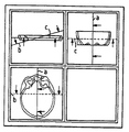
図2は原理図の形態で、像処理装置6ならびに両方の対応付けられている制御手段8、12および表示モニター7を含んでいる本発明による装置を示す。この表示モニターには、例として三次元検査範囲の3つの像A、B、Cが表示される。三次元検査範囲としてここでは頭部撮像の層が表示されている。通常、頭部全体が像技術的に撮像され、その際にこの撮像は、頭部全体の表示として合成されるそれぞれ個々の頭部円板が撮像されるように行われる。像Cは下から、すなわち脚部から見た円板の1つ見え方を示し、図Aは図C中に示されている円板を通る縦断面を示し、また像Bは横断面を示す。像A、B、Cの各々はカラーの像フレームの形態の像特有の標識を付けられている。すなわち、各々の像に特定のカラー標識が付されている。図2中で、これらのカラーフレームは参照符号RA、RBまたはRCを付されている。例えばフレームRAは赤色、フレームRBは緑色、またフレームRCは青色である。
【0019】
さらに図2から解るように、各々の像A、B、Cの中に多くのマーキングMが、記入されている線の形態で示されている。これらの線は、線が表示されている像に関する、線に対応付けられている各々の参照像の像平面の向きを示す。図A中に記入されている、ここでは垂直に延びている線bは像Aに関する像Bの像平面の向きを示し、線cは像Cの像平面の向きを示す。像BおよびCの中でも事情は同様であり、像Bの中で線aは像Aの向きを、また線cは像Cの向きを示し、また像Cの中で線aは像Aの平面の向きを、また線bは像Bの平面の向きを示す。線A、B、Cは、区別を可能にするため、また各像A、BまたはCを対応付けるため、各像フレームRA、RBまたはRCの色に相応してカラーで表示されている。
【0020】
図示の実施例においては、すべての3つの像の像平面は、三次元空間の中で互いに直交している。垂直な平面の向きは、線a、b、cが実線で示されていることにより表示される。医師はここで線a、b、cにより、像A、B、Cがどのように相対的に交わっているかを認識し得る。さらに、例えば像Aとの関連で、像Cを医師がどの方向から観察しているかを認識可能とするため、矢印の形態の追加マーキングZが各々の線a、b、cに付与されている。これらの追加マーキングは各々の線a、b、cと同一の色に保たれる。追加マーキングの各々は、図示の実施例では、ZA、ZB またはZC で示されている。像Cはそれに従えば、例えば下から図A中に示されている円板を見たときの円板状の三次元検査範囲の見え方を示す。
【0021】
図示を簡単にするため表示モニターにおける像表示のみを示す図3ないし7は、図2中に示されている最初の状況から出発した像表示の種々の変更を示す。
【0022】
図3は、像Bの像平面の向きを変化させた状態を示す。このことは像AおよびC中の各線bの変更されたの向きにより表示される。図示の例では、像Bの像平面が像Cに関して“下方に”ずらされている。このことは具体的に、像平面が後頭部の範囲内の三次元検査範囲からの表示であることを意味する。線bは後頭部の範囲にずらされている(図2参照)。相応して像A中の線bは右方にずらされている。像Aは前記のように像C中に示されている対象物を通る縦断面を示す。像Bがずらされたので、そして像Bが像Aに直交しているので、像A中でも強制的に右方への線bのずれが生じなければならない。ここでは像Bの像平面がずらされてはいるが、いずれにせよすべての像は互いに直交している。このことは実線a、bおよびcにより表示されている。
【0023】
図4は、図2から出発して、像B中の表示が、像AおよびBの像平面が互いに直交してはいるが、像BおよびCはもはや互いに直交しないように傾けられた状況を示す。これはマーキングの表示に関して、像平面がもはや互いに直交していないので、像B中の線cが破線で表示され、同じように像C中の線bは破線で表示されるという結果を生ずる。像AおよびCは同じく直交しており、従ってこれに関する線a、cは実線で表示されている。像Bの表示の変更は、制御手段により像A中の線bを回転させ、線運動に相応して像Bの方位も設定することにより簡単に行える。
【0024】
図4中の像表示から出発して、図5では像Cの像平面の方位が像A中の線cの回転により変更されている。線cの向き決めに相応して、像C中の表示も変化する。すなわち、線cが像A中に示されている対象物を通って水平に延びずに、これをある角度のもとに切るので、像C中にも、線の向きにより予め定められた角度のもとに像A中に示されている対象物を観察した際に見える、対象物の範囲しか見えない。これは、像C中では頭部を通る薄い断片のみであり、その際に頭蓋側のみは見えるが、もはや前頭および後頭は見えない。像AおよびCの像平面は互いに直交しており、従って線は実線で示されている。像AおよびCに対する像Bの方位はこの操作により変化しない。
【0025】
図6は、図5から出発し、像B中の線cが回転させられた別の表示を示す。この回転は、像Cがその方位を、像Cの像平面が像Aの像平面と直交しないように変更されることに通ずる。このことは、像A中の線cおよび像C中の線aが同じく破線で表示されていることにより明らかである。像B中の線cの変更およびそれに伴って生ずる像Cの像平面の方位変更の結果として、像C中の線aの向き変更も、これらが多少左方に傾くほどに生ずる。しかしここでも像Aは像Bに直交している。
【0026】
最後に図7は、すべての像平面がもはや互いに直交していない像表示を示す。これは最も複雑な状態であり、すべての像A、B、Cは三次元空間の中で任意の方向に向いている。図7に示されている表示の際には、像Bの中の線aが回転させられたが、このことは像A中の相応する表示も変化することに通ずる。回転により像A、Bの平面はもはや互いに直交せず、従って像A中の線bおよび像B中の線aも破線で示されている。像B中の線aの運動に伴って生ずる像Aの表示の変化の結果として、像C中の線aの経過も変化する。しかしこれらの線は、各々の像を、それらの線が参照像の上に表示される他の2つの像に対する参照像として使用することを可能にする。
【0027】
以上説明したように、各像およびマーキングの発生は、相応に構成されている像処理装置の中で行われる。相応の断層像を得るために医師が行う各像表示の変更は、上記のように、例えば制御マウスのような制御手段により線を動かすことによって行われる。代替的に像表示の変更は、例えばトラックボールの形態の他の制御手段12によっても行える。ここでは像が変更され、線の表示は次いで変更された像により行われる。すなわち作動モードはまさに逆になる。
【0028】
以上説明した実施例では、像A、BおよびCは、いわば表示されている三次元検査範囲を通る視線方向で見た投影像である。しかし医師は、例えば制御手段8、12の1つにより、どのような像を表示するかを選択することもできる。例えば医師は投影像の代わりに、同じ三次元検査範囲の表面像を表示させることもできる。混合した表示、例えば投影像としての像AおよびBと、表面像としての像Cとの表示も可能である。各々の像の中に、選ばれた像形式と無関係にマーキングがフェードインされる。すなわち医師は各々の任意の像表示の際にマーキングにより方位を指定することができる。
【図面の簡単な説明】
【図1】本発明による装置を含んでいる本発明による医学検査設備の原理図。
【図2】表示モニター上の像を拡大して示す、本発明による装置の原理図。
【図3】表示モニターに再現可能な処理された像を示す図。
【図4】表示モニターに再現可能な処理された像を示す図。
【図5】表示モニターに再現可能な処理された像を示す図。
【図6】表示モニターに再現可能な処理された像を示す図。
【図7】表示モニターに再現可能な処理された像を示す図。
【符号の説明】
1 検査装置
2 撮像システム
3 制御装置
5 像の処理および再現のための装置
6 像処理装置
7 表示モニター
8、12 制御手段
9 方位キューブ
A、B、C 像
a、b、c 線
M マーキング
RA カラーフレーム
RB、RC 像フレーム
0 対象物
Z、ZA、ZB、ZC 追加マーキング[0001]
BACKGROUND OF THE INVENTION
The present invention relates to a method for displaying a reproducible image on a display monitor, preferably a method for acquiring digital image data of a three-dimensional examination range of an object by an imaging system of a medical examination facility. .
[0002]
[Prior art]
Especially in the field of medical examination, images of the test object are taken and these images are displayed on a monitor so that the doctor can observe them and make a diagnosis based on them. Such an image is captured by, for example, a magnetic resonance apparatus, a computer tomograph, an X-ray inspection apparatus, or an ultrasonic inspection apparatus. For example, to examine a patient's head, the patient's head is imaged in many tomographic forms. At that time, each three-dimensional inspection range of the object is imaged. That is, the existing digital image data set includes not only information about the appearance of the object but also information about the inside of the three-dimensional object. Thereby, it is possible to display the image of the head in the form of a three-dimensional image, for example, as a projection image or in a three-dimensional form as a surface image. It is important for the physician to obtain as much information as possible in the simplest way possible with the image taken.
[0003]
[Problems to be solved by the invention]
It is an object of the present invention to provide a method for displaying an image on a display monitor that enables analysis by an observer in a simple and obvious manner.
[0004]
[Means for Solving the Problems]
According to the present invention, digital image data of a three-dimensional examination range of an object is preferably acquired by an imaging system of a medical examination facility in order to display and process a reproducible image on a display monitor. In the method, at least two images of a three-dimensional examination range having an arbitrary orientation of the image plane with respect to each other are simultaneously displayed on the display monitor, and in each image, images of each other image relating to the image on which the marking is displayed. Display at least one marking that gives information about the orientation of the plane, and the orientation of the image plane of the individual images, and thus the way the image is viewed, by means of appropriate control means under the display adapted accordingly. To move, especially by shifting or rotating the line or changing the image itself relative to other images that have not been changed with respect to their orientation Ri is solved by changing.
An embodiment of the method according to the invention is as follows.
(1) Three images are reproduced on the display monitor, and two markings relating to the orientation of the other two image planes are reproduced in each image.
(2) Use different markings related to the orientation of the image plane, use the first marking when the image planes are orthogonal to each other, and use the second marking when the image planes intersect at an angle different from 90 °. Use the marking.
(3) Display lines as markings. The line extends over essentially all the images. A solid line is used as the first marking and an intermittent line, preferably a broken line, is used as the second marking, or vice versa.
(4) Each image is associated with an image-specific mark or symbol, and each mark reproduced in the other image attached to this image also shows this mark or is given a symbol. Each image is given a specific color as a label, in particular in the form of a color frame surrounding the image, and the accompanying markings are reproduced in these colors.
(5) In addition, the marking gives information about the local orientation of the image plane of each image with respect to the other images. In order to display the local orientation, each line is displayed shifted laterally or upward in each image.
(6) At least one additional marking, in particular the form of an arrow attached to the line, that displays on each marking, in particular each line, the line-of-sight direction that reproduces the image associated with the marking with respect to the image on which the marking is displayed. Give additional markings.
(7) Use the trackball to change the image plane orientation.
(8) Reproduce a three-dimensional image in the form of a projected image, surface image, or tomographic image as an image. The format of the image to be reproduced can be arbitrarily selected, and all the reproducible images are of the same format or different formats .
[0005]
According to the method according to the invention, on the one hand, many images having different image planes of the three-dimensional examination range, ie the object to be imaged, are reproduced on the display monitor. That is, the image planes may be orthogonal to each other such that, for example, a doctor gives an image display on the one hand in the form of a horizontal section through the three-dimensional examination range, and the second image shows a vertical section to the doctor. The doctor is then given information about the mutual image plane arrangement of the individual images in the form of markings that are faded into each image. That is, the doctor can recognize how the images shown to the doctor are arranged with each other by a simple method. That is, the doctor can link the information amount of the displayed image to each other. This is because each image gives the doctor reference information about the other image. In this case, according to the invention, three images are reproduced on the display monitor, in which case two markings relating to the orientation of the other two image planes are reproduced in each image. This enables greater information mediation.
[0006]
According to the invention, different markings are used in relation to the orientation of the image plane, when the image planes are orthogonal to each other, the first marking is used and the image plane has an angle different from 90 °. When crossing, the second marking is used. The purpose of marking is to display a line. It is advantageous that these lines extend over essentially all images. When using two different markings, a solid line is used as the first marking and an intermittent line, preferably a dashed line, is used as the second marking, or vice versa, so that the physician can easily identify the marking. As long as it is guaranteed to be obtained, it is advantageous.
[0007]
If more than two images are displayed, there is a simple association between the markings shown in the first image, for example lines, and the accompanying images in which the orientation of the image plane is to be displayed. As possible, each image is associated with an image-specific sign or symbol, and each marking that accompanies this image and that is reproduced in another image also indicates this sign or symbol Is advantageously associated. At that time, each image is associated with a specific color as a mark, particularly in the form of a color frame surrounding the image, and the attached marking is also reproduced with these colors. For example, if three separate images are used, the first image may have a red frame, the second image may have a green frame, and the third image may have a blue frame. In doing so, the green and blue lines in the first image indicate the orientation of the planes of images 2 and 3, so that the red and blue lines in the second image are
[0008]
Furthermore, it is advantageous to give each line an additional marking indicating the direction of the line of sight from which the image corresponding to each marking is observed in association with the image in which the marking has been faded in. This is done in particular in the form of arrows attached to each line.
[0009]
According to the invention, the marking additionally provides information about the local orientation of the image plane of each image relative to the other image. That is, each line in each image is displayed shifted laterally or upward, particularly simply, so that the relative orientation of the individual images is shown in a simple manner.
[0010]
According to the invention, the orientation of the image plane of the image, and thus also the way the image is viewed, is changed under a display adapted to the marking so that the doctor can determine the 3D examination range in any display. Is done. That is, the doctor can, for example, tilt or rotate the projected image shown as image 3 so that the three-dimensional examination range can be observed at other viewing angles, with the corresponding markings automatically adapted or adapted. It is made to follow. It is appropriate to make the change, in particular by moving the markings by means of suitable control means including a control mouse, in particular by shifting or rotating the lines. That is, line motion results in a change in the image or display. Alternatively or additionally, the image plane orientation can be changed by a trackball or the like. That is, the image display itself is changed here and the marking display is adapted accordingly. As described above, as described above, a three-dimensional image is reproduced in the form of a projection image, a surface image, or a tomographic image. The format of the image to be reproduced can be selected. That is, the user can select whether to display, for example, a projected image marking means or a tomographic image. The marking always gives the physician appropriate information regardless of the selected image type. At that time, different image formats can be displayed simultaneously.
[0011]
The invention along with methods, and the image processing apparatus having a digital image data of the three-dimensional examination region of the object, in the processing and reproducing apparatus in a digital image and a display monitor for reproducing an image, display monitor At least two images of a three-dimensional inspection range having arbitrary orientations in the image plane relative to each other can be displayed simultaneously, and the image processing device is configured to generate reproducible markings in the images, At least one marking can be displayed which gives information about the orientation of the image plane of each other image with respect to the image on which the marking is displayed, and the orientation of the image plane of the individual image and hence the way the image is viewed Under the display adapted to the above, the markings can be moved by suitable control means, in particular by shifting or rotating the lines, or the image itself. By changing to other image that have not changed with respect to the orientation, and changes.
Embodiments of the present invention relating to digital image processing and reproduction apparatus are as follows.
(11) Three images are reproducible on the display monitor, and the image processing device is configured to generate and reproduce two markings for the image planes of two other images in the image, respectively.
(12) The image processing device is configured to generate markings of different types relative to the orientation of the image plane, the first marking indicating image planes that are orthogonal to each other and the second marking is 90 ° Mark image planes that intersect at different angles.
(13) The marking is a line. A line extends across all images. The first marking is a solid line and the second marking is an intermittent line, preferably a broken line, or vice versa.
(14) At least one additional marking, in particular a line, for the image processing device to display a line-of-sight direction that reproduces the image associated with the marking for each marking, in particular for each line with respect to the image on which the marking is displayed. Are configured to generate additional markings in the form of arrows associated with the. For modification, markings, in particular lines, are moved using a control means in the form of a control mouse, in particular the lines are shifted or rotated. A trackball for changing the image plane orientation of the image is provided .
An image processing apparatus provided by the present invention capable of processing transmitted digital image data is configured to generate a marking each time to reproduce many different images on a display monitor. This is particularly advantageous. In so doing, three images may be reproducible on the display monitor and the image processing device is configured to generate and reproduce two markings in the image, each relating to the image plane of the other image. The image processing device may be further configured to generate different types of markings related to the orientation of the image plane. For example, if the image planes are orthogonal to each other, the first marking is used, and if the image planes intersect at an angle different from 90 °, a second marking of a different form from the first marking is used. Is done. In doing so, a line extending over all the images is displayed in a manner appropriate to the purpose. These lines may be solid lines or, if different markings are used, intermittent lines, for example broken lines.
[0012]
In order to facilitate the mapping of the marking to each image whose orientation should be indicated by marking (problems arise when four or more images are displayed), according to the present invention, From the side, an image-specific sign or symbol can be associated with each image, and each mark or symbol associated with the image and reproducible in other images can be associated with the image as well. That is, the image processing device has the ability to generate a corresponding sign or symbol, in which case the image-specific mark serves a particular purpose, in particular a specific color in the form of a color frame surrounding the image, and is attached. The marking is then shown in exactly this color. In order to provide information on the local orientation of each image in relation to the display of the other image in the image plane, the image processing device additionally additionally relates to the local orientation of each image in relation to the display of the other image in the image plane. It may be configured to generate markings that contain information, for example in the form of lines that are shifted laterally or upwards. In addition, with respect to the image on which the marking is displayed, the marking is displayed on each marking, in particular on each line, so that the doctor can easily recognize from which direction the reference image indicated by the marking is observing. It is appropriate to provide at least one additional marking, particularly in the form of an arrow attached to the line, which displays the line-of-sight direction reproducing the image associated with the marking.
[0013]
Furthermore, according to the invention, the orientation of the image plane of the image and thus also the appearance of the image can be changed under a correspondingly adapted display of the marking, which is the first implementation of the invention. According to an example, this is done by shifting or moving the marking. The image display now follows the movement of the line. Additionally or alternatively, a trackball can be provided that changes the image orientation of the image. The marking is changed accordingly.
[0014]
Finally, the invention further relates to a medical examination apparatus comprising an imaging system for acquiring image data of an examination object and an apparatus of the above-mentioned type which is provided with digital form of image data.
[0015]
【Example】
Other advantages, features and details of the present invention will become apparent from the examples and drawings described below.
[0016]
FIG. 1 shows a medical
[0017]
As indicated by the double arrow A, the image data of the object O acquired by the imaging system 2 is given to the
[0018]
FIG. 2 shows in the form of a principle diagram an apparatus according to the invention comprising an image processing device 6 and both associated control means 8, 12 and a
[0019]
As can also be seen from FIG. 2, in each of the images A, B, C a number of markings M are shown in the form of filled lines. These lines indicate the orientation of the image plane of each reference image associated with the line with respect to the image on which the line is displayed. In FIG. A, a line b extending vertically here indicates the orientation of the image plane of the image B with respect to the image A, and the line c indicates the orientation of the image plane of the image C. The situation is the same in the images B and C. In the image B, the line a indicates the direction of the image A, the line c indicates the direction of the image C, and in the image C, the line a indicates the plane of the image A. The line b indicates the direction of the plane of the image B. Lines A, B and C are displayed in color corresponding to the color of each image frame R A , R B or R C in order to enable distinction and to associate each image A, B or C. .
[0020]
In the illustrated embodiment, the image planes of all three images are orthogonal to each other in a three-dimensional space. The orientation of the vertical plane is indicated by the lines a, b, and c being shown as solid lines. Here, the doctor can recognize how the images A, B, and C intersect relatively by the lines a, b, and c. Further, for example, in relation to the image A, an additional marking Z in the form of an arrow is given to each line a, b, c in order to make it possible to recognize from which direction the doctor is observing the image C. . These additional markings are kept in the same color as each line a, b, c. Each additional marking is designated as Z A , Z B or Z C in the illustrated embodiment. According to this, the image C shows how the disc-shaped three-dimensional inspection range looks when, for example, the disc shown in FIG. A is viewed from below.
[0021]
FIGS. 3-7, which show only the image display on the display monitor for ease of illustration, show various modifications of the image display starting from the initial situation shown in FIG.
[0022]
FIG. 3 shows a state in which the orientation of the image plane of the image B is changed. This is indicated by the changed orientation of each line b in images A and C. In the example shown, the image plane of image B is shifted “down” with respect to image C. This specifically means that the image plane is a display from a three-dimensional examination range within the occipital region. The line b is shifted to the range of the back of the head (see FIG. 2). Correspondingly, line b in image A is shifted to the right. Image A shows a longitudinal section through the object shown in image C as described above. Since the image B is shifted, and since the image B is orthogonal to the image A, a shift of the line b to the right in the image A must be forced. Here, the image plane of the image B is shifted, but in any case, all the images are orthogonal to each other. This is indicated by solid lines a, b and c.
[0023]
4 starts from FIG. 2 and shows that the display in image B is tilted so that image planes of images A and B are orthogonal to each other, but images B and C are no longer orthogonal to each other. Show. This results in the display of the marking, since the image planes are no longer orthogonal to each other, so that the line c in the image B is displayed as a broken line, and similarly the line b in the image C is displayed as a broken line. Images A and C are also orthogonal, so the lines a and c associated therewith are displayed as solid lines. The display of the image B can be easily changed by rotating the line b in the image A by the control means and setting the azimuth of the image B according to the line motion.
[0024]
Starting from the image display in FIG. 4, in FIG. 5, the orientation of the image plane of the image C is changed by the rotation of the line c in the image A. Corresponding to the orientation of line c, the display in image C also changes. That is, the line c does not extend horizontally through the object shown in the image A, but is cut at a certain angle, so that the angle determined in advance in the image C also depends on the direction of the line. Only the range of the object that can be seen when observing the object shown in the image A is visible. This is only a thin fragment passing through the head in image C, where only the skull side is visible, but the frontal and occipital areas are no longer visible. The image planes of images A and C are orthogonal to each other, so the lines are shown as solid lines. The orientation of image B relative to images A and C is not changed by this operation.
[0025]
FIG. 6 shows another display starting from FIG. 5 in which the line c in the image B has been rotated. This rotation leads to the image C changing its orientation so that the image plane of the image C is not orthogonal to the image plane of the image A. This is apparent from the fact that the line c in the image A and the line a in the image C are also displayed by broken lines. As a result of the change in the line c in the image B and the accompanying change in the orientation of the image plane of the image C, the change in the direction of the line a in the image C also occurs as they are tilted somewhat to the left. However, image A is also orthogonal to image B here.
[0026]
Finally, FIG. 7 shows an image display in which all image planes are no longer orthogonal to each other. This is the most complicated state, and all the images A, B, and C are oriented in an arbitrary direction in the three-dimensional space. In the case of the display shown in FIG. 7, the line a in the image B has been rotated, which leads to the corresponding display in the image A also changing. Due to the rotation, the planes of the images A and B are no longer perpendicular to each other, so the line b in the image A and the line a in the image B are also indicated by broken lines. As a result of the change in display of image A that accompanies movement of line a in image B, the course of line a in image C also changes. These lines, however, allow each image to be used as a reference image for the other two images where they are displayed on top of the reference image.
[0027]
As described above, the generation of each image and marking is performed in an image processing apparatus configured accordingly. The change of each image display performed by the doctor in order to obtain a corresponding tomographic image is performed by moving a line by a control means such as a control mouse as described above. Alternatively, the image display can be changed by other control means 12, for example in the form of a trackball. Here the image is changed and the display of the line is then performed with the changed image. That is, the mode of operation is exactly reversed.
[0028]
In the embodiment described above, the images A, B, and C are so-called projection images viewed in the line-of-sight direction passing through the displayed three-dimensional inspection range. However, the doctor can also select what kind of image is displayed by one of the control means 8 and 12, for example. For example, the doctor can display a surface image of the same three-dimensional examination range instead of the projection image. Mixed display, for example, display of images A and B as projection images and image C as surface images is also possible. Within each image, the markings are faded in regardless of the selected image type. That is, the doctor can designate the direction by marking when displaying each arbitrary image.
[Brief description of the drawings]
1 is a principle diagram of a medical examination facility according to the present invention including a device according to the present invention;
FIG. 2 is a principle diagram of an apparatus according to the present invention showing an enlarged image on a display monitor.
FIG. 3 shows a processed image that can be reproduced on a display monitor.
FIG. 4 shows a processed image that can be reproduced on a display monitor.
FIG. 5 shows a processed image that can be reproduced on a display monitor.
FIG. 6 shows a processed image that can be reproduced on a display monitor.
FIG. 7 shows a processed image that can be reproduced on a display monitor.
[Explanation of symbols]
DESCRIPTION OF
Claims (24)
表示モニターに互いに像平面の任意の方位を有する三次元検査範囲の少なくとも2つの像を同時に表示し、各々の像の中に、マーキングが表示される像に関するそれぞれ他の像の、像平面の向きに関する情報を与える少なくとも1つのマーキングを表示し、
個々の像の像平面の方位、従って像の見方を、マーキングの相応に適合された表示のもとに、適当な制御手段によりマーキングを動かすことによって又は像自体をその方位に関して変更されていない他の像に対して変更することによって、変更することを特徴とする表示モニターに再現可能な像の表示方法。In a method for acquiring digital image data of a three-dimensional inspection range of an object by an imaging system in order to display and process a reproducible image on a display monitor,
Simultaneously displaying at least two images of the three-dimensional examination region having an arbitrary orientation of one another image plane on the display monitor, in each image, the respective other image related image marking is displayed, the image plane orientation It gives information about the display of at least one marking,
The orientation of the image plane of the individual image, and thus the way the image is viewed, by moving the marking by suitable control means, under a display adapted to the marking, or the image itself is not changed with respect to its orientation A method of displaying an image reproducible on a display monitor, wherein the image is changed by changing the image .
表示モニター(7)に互いに像平面の任意の方位を有する三次元検査範囲の少なくとも2つの像(A、B、C)が同時に表示可能であり、
像処理装置が像(A、B、C)の中に再現可能なマーキングを発生するべく構成され、
各々の像(A、B、C)の中に、マーキングが表示される像に関するそれぞれ他の像の像平面の向きに関する情報を与える少なくとも1つのマーキング(M)が表示可能であり、
個々の像の像平面の方位、従って像の見方を、マーキングの相応に適合された表示のもとに、適当な制御手段によりマーキングを動かすことによって又は像自体をその方位に関して変更されていない他の像に対して変更することによって、変更することを特徴とするディジタル像の処理および再現装置。 In a digital image processing and reproduction apparatus including an image processing apparatus having digital image data of a three-dimensional inspection range of an object and a display monitor for reproducing an image ,
On the display monitor (7), at least two images (A, B, C) in a three-dimensional inspection range having arbitrary orientations on the image plane can be displayed simultaneously ,
Image processing device image (A, B, C) is configured to generate a reproducible markings in,
In each image (A, B, C) at least one marking (M) can be displayed that gives information about the orientation of the image plane of each other image with respect to the image on which the marking is displayed ,
The orientation of the image plane of the individual image, and thus the way the image is viewed, by moving the marking by suitable control means, under a display adapted to the marking, or the image itself is not changed with respect to its orientation An apparatus for processing and reproducing a digital image, characterized in that the image is changed by changing the image .
Applications Claiming Priority (2)
| Application Number | Priority Date | Filing Date | Title |
|---|---|---|---|
| DE19854241.0 | 1998-11-24 | ||
| DE19854241.0A DE19854241B4 (en) | 1998-11-24 | 1998-11-24 | A method of displaying images displayed on a display monitor, and a device for processing and reproducing digital images |
Publications (2)
| Publication Number | Publication Date |
|---|---|
| JP2000157496A JP2000157496A (en) | 2000-06-13 |
| JP4484286B2 true JP4484286B2 (en) | 2010-06-16 |
Family
ID=7888883
Family Applications (1)
| Application Number | Title | Priority Date | Filing Date |
|---|---|---|---|
| JP33046999A Expired - Fee Related JP4484286B2 (en) | 1998-11-24 | 1999-11-19 | Image display method reproducible on display monitor and digital image processing and reproduction device |
Country Status (3)
| Country | Link |
|---|---|
| US (1) | US6603868B1 (en) |
| JP (1) | JP4484286B2 (en) |
| DE (1) | DE19854241B4 (en) |
Families Citing this family (27)
| Publication number | Priority date | Publication date | Assignee | Title |
|---|---|---|---|---|
| DE19854131A1 (en) * | 1998-11-24 | 2000-05-31 | Siemens Ag | Displaying and processing image displayed on monitor for medical examination apparatus by defining volume region of image which is to be removed from display using marking device |
| JP2001156135A (en) * | 1999-11-29 | 2001-06-08 | Hitachi Ltd | Method and device for sorting defective image and manufacturing method of semiconductor device using them |
| US6761689B2 (en) * | 2000-08-17 | 2004-07-13 | Koninklijke Philips Electronics N.V. | Biplane ultrasonic imaging |
| DE10045873A1 (en) * | 2000-09-14 | 2002-03-28 | Leica Microsystems | Three-dimensional specimen analysis and evaluation method involves outputting plane extending through two defined points of specimen data set, graphically |
| JP4653324B2 (en) * | 2001-02-20 | 2011-03-16 | 東芝医用システムエンジニアリング株式会社 | Image display apparatus, image display program, image processing apparatus, and medical image diagnostic apparatus |
| US7596257B2 (en) * | 2001-10-31 | 2009-09-29 | Imagnosis Inc. | Medical image processing device method and program for displaying a section for a clinical application |
| DE10157268A1 (en) * | 2001-11-22 | 2003-06-12 | Philips Intellectual Property | Method and device for the simultaneous display of arbitrarily selectable complementary sectional images |
| DE10243162B4 (en) * | 2002-09-17 | 2005-10-06 | Siemens Ag | Computer-aided display method for a 3D object |
| US9155373B2 (en) * | 2004-08-02 | 2015-10-13 | Invention Science Fund I, Llc | Medical overlay mirror |
| EP1776605A1 (en) * | 2004-08-05 | 2007-04-25 | Koninklijke Philips Electronics N.V. | Imaging system |
| JP4208791B2 (en) * | 2004-08-11 | 2009-01-14 | キヤノン株式会社 | Image processing apparatus, control method therefor, and program |
| US7496222B2 (en) * | 2005-06-23 | 2009-02-24 | General Electric Company | Method to define the 3D oblique cross-section of anatomy at a specific angle and be able to easily modify multiple angles of display simultaneously |
| US8199168B2 (en) * | 2005-11-15 | 2012-06-12 | General Electric Company | System and method for 3D graphical prescription of a medical imaging volume |
| DE102006048834A1 (en) | 2006-10-16 | 2008-04-17 | Rust, Georg-Friedemann, Dr. | Three-dimensional measuring data set representing method for e.g. virtual coloscopy, involves selecting value of orientation parameter by controller to determine orientation of presentation plane with respect to another presentation plane |
| EP2162086B1 (en) * | 2007-10-01 | 2019-02-27 | Orthosoft Inc. | Construction of a non-imaged view of an object using acquired images |
| US8900148B2 (en) * | 2011-03-09 | 2014-12-02 | Fujifilm Corporation | Ultrasound diagnostic apparatus |
| US20160000414A1 (en) | 2014-07-02 | 2016-01-07 | Covidien Lp | Methods for marking biopsy location |
| US9603668B2 (en) | 2014-07-02 | 2017-03-28 | Covidien Lp | Dynamic 3D lung map view for tool navigation inside the lung |
| JP6534193B2 (en) | 2014-07-02 | 2019-06-26 | コヴィディエン リミテッド パートナーシップ | Real-time automatic registration feedback |
| US9770216B2 (en) | 2014-07-02 | 2017-09-26 | Covidien Lp | System and method for navigating within the lung |
| CA2953146A1 (en) | 2014-07-02 | 2016-01-07 | Covidien Lp | System and method for segmentation of lung |
| US9754367B2 (en) | 2014-07-02 | 2017-09-05 | Covidien Lp | Trachea marking |
| AU2015284303B2 (en) | 2014-07-02 | 2019-07-25 | Covidien Lp | System and method for detecting trachea |
| US10643371B2 (en) | 2014-08-11 | 2020-05-05 | Covidien Lp | Treatment procedure planning system and method |
| US10986990B2 (en) | 2015-09-24 | 2021-04-27 | Covidien Lp | Marker placement |
| US10709352B2 (en) | 2015-10-27 | 2020-07-14 | Covidien Lp | Method of using lung airway carina locations to improve ENB registration |
| US11224392B2 (en) | 2018-02-01 | 2022-01-18 | Covidien Lp | Mapping disease spread |
Family Cites Families (17)
| Publication number | Priority date | Publication date | Assignee | Title |
|---|---|---|---|---|
| US4879668A (en) * | 1986-12-19 | 1989-11-07 | General Electric Company | Method of displaying internal surfaces of three-dimensional medical images |
| US5170347A (en) * | 1987-11-27 | 1992-12-08 | Picker International, Inc. | System to reformat images for three-dimensional display using unique spatial encoding and non-planar bisectioning |
| US5186176A (en) * | 1990-04-11 | 1993-02-16 | Kabushiki Kaisha Toshiba | Ultrasonic diagnosis apparatus |
| US5201035A (en) * | 1990-07-09 | 1993-04-06 | The United States Of America As Represented By The Secretary Of The Air Force | Dynamic algorithm selection for volume rendering, isocontour and body extraction within a multiple-instruction, multiple-data multiprocessor |
| DE4117117A1 (en) * | 1991-05-25 | 1992-11-26 | Hoehne Karl Heinz Prof Dr | Three=dimensional imaging display of object - scanning object to generate sequence of images that can be reconstructed to display specific features |
| US5371778A (en) * | 1991-11-29 | 1994-12-06 | Picker International, Inc. | Concurrent display and adjustment of 3D projection, coronal slice, sagittal slice, and transverse slice images |
| US5734384A (en) * | 1991-11-29 | 1998-03-31 | Picker International, Inc. | Cross-referenced sectioning and reprojection of diagnostic image volumes |
| DE4203447C2 (en) * | 1992-02-07 | 1993-11-25 | Digital Diagnostik In Deutschl | Method and device for digitizing analog x-ray images in x-ray diagnostics |
| FR2705223A1 (en) * | 1993-05-13 | 1994-11-25 | Ge Medical Syst Sa | Method for acquiring images of a body by rotational placement |
| US5454371A (en) * | 1993-11-29 | 1995-10-03 | London Health Association | Method and system for constructing and displaying three-dimensional images |
| US6104828A (en) * | 1994-03-24 | 2000-08-15 | Kabushiki Kaisha Topcon | Ophthalmologic image processor |
| US5982953A (en) * | 1994-09-02 | 1999-11-09 | Konica Corporation | Image displaying apparatus of a processed image from temporally sequential images |
| JP3334025B2 (en) * | 1995-11-13 | 2002-10-15 | ミノルタ株式会社 | Image forming device |
| DE19615595A1 (en) * | 1996-04-19 | 1997-10-23 | Siemens Ag | Digital imaging system operating method |
| US5891030A (en) * | 1997-01-24 | 1999-04-06 | Mayo Foundation For Medical Education And Research | System for two dimensional and three dimensional imaging of tubular structures in the human body |
| US6211884B1 (en) * | 1998-11-12 | 2001-04-03 | Mitsubishi Electric Research Laboratories, Inc | Incrementally calculated cut-plane region for viewing a portion of a volume data set in real-time |
| US6266453B1 (en) * | 1999-07-26 | 2001-07-24 | Computerized Medical Systems, Inc. | Automated image fusion/alignment system and method |
-
1998
- 1998-11-24 DE DE19854241.0A patent/DE19854241B4/en not_active Revoked
-
1999
- 1999-11-19 JP JP33046999A patent/JP4484286B2/en not_active Expired - Fee Related
- 1999-11-22 US US09/435,442 patent/US6603868B1/en not_active Expired - Lifetime
Also Published As
| Publication number | Publication date |
|---|---|
| DE19854241B4 (en) | 2014-03-06 |
| JP2000157496A (en) | 2000-06-13 |
| US6603868B1 (en) | 2003-08-05 |
| DE19854241A1 (en) | 2000-06-08 |
Similar Documents
| Publication | Publication Date | Title |
|---|---|---|
| JP4484286B2 (en) | Image display method reproducible on display monitor and digital image processing and reproduction device | |
| US8294709B2 (en) | Method and apparatus for integrating three-dimensional and two-dimensional monitors with medical diagnostic imaging workstations | |
| JP5427179B2 (en) | Visualization of anatomical data | |
| EP1825811B1 (en) | Image display apparatus and x-ray computed tomography apparatus | |
| US9042612B2 (en) | Image handling and display in X-ray mammography and tomosynthesis | |
| EP1207495B1 (en) | Three-dimensional image display, display method, program for display | |
| US20040165766A1 (en) | Method and apparatus for forming and displaying projection image from a plurality of sectional images | |
| US20070182731A1 (en) | Method and device for virtual endoscopy in a hollow tract | |
| Dückelmann et al. | Three‐dimensional ultrasound in evaluating the fetus | |
| US20120320167A1 (en) | Image processing system and method | |
| US7889894B2 (en) | Method of navigation in three-dimensional image data | |
| EP3003155B1 (en) | Method and device for displaying a first image and a second image of an object | |
| JP2000210261A (en) | Method and apparatus for displaying and processing image reproducible on instruction monitor | |
| JPH07136175A (en) | Real-time medical device and method | |
| JPS63261472A (en) | Method of generating image of layer of object and apparatus for implementing the same | |
| JP5268229B2 (en) | 3D vector quantity visualization method and apparatus | |
| JPH0838433A (en) | Medical image diagnostic device | |
| US9628773B2 (en) | Image processing apparatus, image processing method, and medical image diagnosis apparatus | |
| US20080037702A1 (en) | Real-Time Navigational Aid System for Radiography | |
| Merz | Current 3D/4D ultrasound technology in prenatal diagnosis | |
| US20100215150A1 (en) | Real-time Assisted Guidance System for a Radiography Device | |
| JP4430142B2 (en) | Medical image processing apparatus and medical image processing method | |
| JPH1043178A (en) | Method, device for setting reconstitutive faces, reconstitutive image preparing method and x-ray ct device | |
| Martin et al. | Stereographic viewing of 3D ultrasound images: a novelty or a tool? | |
| JP2508106B2 (en) | Image display controller |
Legal Events
| Date | Code | Title | Description |
|---|---|---|---|
| A621 | Written request for application examination |
Free format text: JAPANESE INTERMEDIATE CODE: A621 Effective date: 20061116 |
|
| A131 | Notification of reasons for refusal |
Free format text: JAPANESE INTERMEDIATE CODE: A131 Effective date: 20090915 |
|
| A521 | Request for written amendment filed |
Free format text: JAPANESE INTERMEDIATE CODE: A523 Effective date: 20091214 |
|
| RD03 | Notification of appointment of power of attorney |
Free format text: JAPANESE INTERMEDIATE CODE: A7423 Effective date: 20091214 |
|
| TRDD | Decision of grant or rejection written | ||
| A01 | Written decision to grant a patent or to grant a registration (utility model) |
Free format text: JAPANESE INTERMEDIATE CODE: A01 Effective date: 20100223 |
|
| A01 | Written decision to grant a patent or to grant a registration (utility model) |
Free format text: JAPANESE INTERMEDIATE CODE: A01 |
|
| A61 | First payment of annual fees (during grant procedure) |
Free format text: JAPANESE INTERMEDIATE CODE: A61 Effective date: 20100323 |
|
| R150 | Certificate of patent or registration of utility model |
Free format text: JAPANESE INTERMEDIATE CODE: R150 Ref document number: 4484286 Country of ref document: JP Free format text: JAPANESE INTERMEDIATE CODE: R150 |
|
| FPAY | Renewal fee payment (event date is renewal date of database) |
Free format text: PAYMENT UNTIL: 20130402 Year of fee payment: 3 |
|
| FPAY | Renewal fee payment (event date is renewal date of database) |
Free format text: PAYMENT UNTIL: 20130402 Year of fee payment: 3 |
|
| FPAY | Renewal fee payment (event date is renewal date of database) |
Free format text: PAYMENT UNTIL: 20140402 Year of fee payment: 4 |
|
| R250 | Receipt of annual fees |
Free format text: JAPANESE INTERMEDIATE CODE: R250 |
|
| R250 | Receipt of annual fees |
Free format text: JAPANESE INTERMEDIATE CODE: R250 |
|
| R250 | Receipt of annual fees |
Free format text: JAPANESE INTERMEDIATE CODE: R250 |
|
| R250 | Receipt of annual fees |
Free format text: JAPANESE INTERMEDIATE CODE: R250 |
|
| R250 | Receipt of annual fees |
Free format text: JAPANESE INTERMEDIATE CODE: R250 |
|
| R250 | Receipt of annual fees |
Free format text: JAPANESE INTERMEDIATE CODE: R250 |
|
| LAPS | Cancellation because of no payment of annual fees |