JP4483568B2 - Liquid jet head - Google Patents
Liquid jet head Download PDFInfo
- Publication number
- JP4483568B2 JP4483568B2 JP2004369660A JP2004369660A JP4483568B2 JP 4483568 B2 JP4483568 B2 JP 4483568B2 JP 2004369660 A JP2004369660 A JP 2004369660A JP 2004369660 A JP2004369660 A JP 2004369660A JP 4483568 B2 JP4483568 B2 JP 4483568B2
- Authority
- JP
- Japan
- Prior art keywords
- head
- nozzle
- droplet discharge
- liquid
- discharge surface
- Prior art date
- Legal status (The legal status is an assumption and is not a legal conclusion. Google has not performed a legal analysis and makes no representation as to the accuracy of the status listed.)
- Expired - Fee Related
Links
Images


Description
本発明は、インクジェット式記録ヘッド等の液体噴射ヘッドに係り、特に、複数のノズル開口を列設してなるノズル形成部材を備え、ノズル開口から液体を液滴として吐出可能な液体噴射ヘッドに関する。 The present invention relates to a liquid ejecting head such as an ink jet recording head, and more particularly to a liquid ejecting head including a nozzle forming member having a plurality of nozzle openings arranged in a row and capable of ejecting liquid as droplets from the nozzle openings.
圧力室内の液体に圧力変動を生じさせることでノズル開口から液滴として吐出させる液体噴射ヘッドとしては、例えば、プリンタ等の画像記録装置に用いられるインクジェット式記録ヘッド、液晶ディスプレー等のカラーフィルタの製造に用いられる色材噴射ヘッド、有機EL(Electro Luminescence)ディスプレー、FED(面発光ディスプレー)等の電極形成に用いられる電極材噴射ヘッド、バイオチップ(生物化学素子)の製造に用いられる生体有機物噴射ヘッド等がある。 Examples of liquid ejecting heads that discharge liquid droplets from nozzle openings by causing pressure fluctuations in the pressure chambers include, for example, ink jet recording heads used in image recording apparatuses such as printers, and manufacture of color filters such as liquid crystal displays. Material injection heads used in manufacturing, electrode material injection heads used for electrode formation of organic EL (Electro Luminescence) displays, FEDs (surface emitting displays), etc., and bioorganic matter injection heads used in the manufacture of biochips (biochemical elements) Etc.
このような液体噴射ヘッドには種々の形式があるが、例えば、インクジェット式記録装置(以下、単にプリンタという)におけるインクジェット式記録ヘッド(以下、記録ヘッドという)は、リザーバから圧力室を経てノズル開口に至る一連の液体流路が形成された流路ユニットや圧力室の容積を変動可能な圧力発生素子を有するアクチュエータユニット等を備えたヘッドユニット(ヘッド本体)と、液体流路に連通する複数のノズル開口を列設してなるノズル列を有する金属製のノズルプレートと、これらのヘッドユニット及びノズルプレート(ノズル形成部材の一種)が固定される樹脂製のヘッドケースとを備えたものがある。 There are various types of such liquid ejecting heads. For example, an ink jet recording head (hereinafter referred to as a recording head) in an ink jet recording apparatus (hereinafter simply referred to as a printer) has a nozzle opening from a reservoir through a pressure chamber. A head unit (head body) including a flow path unit in which a series of liquid flow paths leading to the pressure chamber, an actuator unit having a pressure generating element capable of changing the volume of the pressure chamber, and the like, and a plurality of fluid channels communicating with the liquid flow path Some include a metal nozzle plate having a nozzle row in which nozzle openings are arranged, and a resin head case to which the head unit and the nozzle plate (a kind of nozzle forming member) are fixed.
このような記録ヘッドにおいて、ノズル開口周りの状態、すなわち、ノズル開口周囲のインク等の液体の濡れの状態によっては、吐出する液滴に飛行曲がりが発生する場合がある。つまり、ノズル開口の周囲がインク等の液体で濡れていると、この部分の表面張力によって吐出時の液滴が引っ張られ、その結果、飛行曲がりが発生する。このような飛行曲がりを防止すべく、ノズル開口周囲のインク等の液体の付着を無くすための撥液処理をノズルプレートの液滴吐出側の液滴吐出面に施すことが一般的となっている。 In such a recording head, depending on a state around the nozzle opening, that is, a wet state of a liquid such as ink around the nozzle opening, a flying bend may occur in the ejected liquid droplets. In other words, when the periphery of the nozzle opening is wet with a liquid such as ink, the droplet at the time of ejection is pulled by the surface tension of this portion, and as a result, flight bending occurs. In order to prevent such flight bending, it is common to apply a liquid repellent treatment on the liquid droplet ejection surface of the nozzle plate to eliminate adhesion of liquid such as ink around the nozzle opening. .
この記録ヘッドにおけるノズルプレートは、ノズルプレートのノズル開口を露出可能な露出窓部が開設された金属製のヘッドカバーによってヘッドケースに固定されるようになっている。このヘッドカバーは、ヘッドユニットやノズルプレートを保護し、各部の剥離を防止する機能を果たすものである。また、このヘッドカバーは、接地電位に設定されており、ノズルプレートに接触して導通することで、記録紙等から発生した静電気をノズルプレートから除電するようになっている。これにより、例えば、静電気がノズルプレートを通じて伝達することによる駆動回路等の静電破壊や、この静電気がノイズとして駆動信号に重畳することによる誤作動等の不具合を防止するようになっている(例えば、特許文献1参照)。 The nozzle plate in the recording head is fixed to the head case by a metal head cover in which an exposure window portion capable of exposing the nozzle opening of the nozzle plate is opened. The head cover functions to protect the head unit and the nozzle plate and prevent peeling of each part. Further, the head cover is set to a ground potential, and static electricity generated from the recording paper or the like is discharged from the nozzle plate by contacting the nozzle plate and conducting. This prevents, for example, problems such as electrostatic breakdown of the drive circuit due to the static electricity being transmitted through the nozzle plate and malfunction due to the static electricity being superimposed on the drive signal as noise (for example, , See Patent Document 1).
ところで、近年、この種のプリンタでは、画質の向上を図るため顔料系のインクや、耐水性を向上させるため耐水性インクを使用する傾向がある。このようなインクの溶媒は、従来の水に対し、樹脂系の分散剤が用いられている。そのため、ノズル開口周辺に付着したインクに起因する飛行曲がり等の吐出不良の防止するためノズルプレートの液滴吐出面に形成される撥液被膜層も、上記のようなインクに対応した撥液性の高いものが必要とされる。そこで、撥液性や品質の大幅向上に加え、被膜処理の工程の簡略化によるコストダウンを図るため、ノズルプレートの液滴吐出面に、例えば、薄膜蒸着技術を用いた撥液処理を施すようになってきている。この撥液処理によりノズルプレートの液滴吐出面には、例えばフッ素樹脂を従来のものより多く含有する撥液被膜層が形成される。ところが、フッ素樹脂は絶縁性が高いため、撥液性を高めるためにこのフッ素樹脂の含有率を増加させると、これに伴ってノズルプレートの液滴吐出面の絶縁性が高まってしまう。このため、上記特許文献1のように、ヘッドカバーをノズルプレートの液滴吐出面に単に重畳させる構成のものでは、ノズルプレートとヘッドカバーとの導通が確保し難くなるという問題があった。
By the way, in recent years, this type of printer has a tendency to use pigment-based ink to improve image quality and water-resistant ink to improve water resistance. As a solvent for such an ink, a resin-based dispersant is used with respect to conventional water. Therefore, the liquid repellent coating layer formed on the droplet ejection surface of the nozzle plate to prevent ejection defects such as flying bends caused by the ink adhering to the periphery of the nozzle opening also has liquid repellency corresponding to the above inks. Higher ones are needed. Therefore, in order to reduce costs by simplifying the coating process, in addition to significantly improving the liquid repellency and quality, the liquid droplet ejection surface of the nozzle plate is subjected to a liquid repellency process using, for example, a thin film deposition technique. It is becoming. By this liquid repellent treatment, a liquid repellent coating layer containing, for example, more fluorine resin than the conventional one is formed on the droplet discharge surface of the nozzle plate. However, since the fluororesin has a high insulating property, if the content of the fluororesin is increased in order to improve the liquid repellency, the insulating property of the droplet discharge surface of the nozzle plate is increased accordingly. For this reason, there is a problem in that it is difficult to ensure conduction between the nozzle plate and the head cover in the configuration in which the head cover is simply superimposed on the liquid droplet ejection surface of the nozzle plate as in
本発明は、このような事情に鑑みてなされたものであり、その目的は、ノズル形成部材の液滴吐出面の撥液性を向上させても、ノズル形成部材とヘッドカバーとの導通を確保することが可能な液体噴射ヘッドを提供することにある。 The present invention has been made in view of such circumstances, and the object thereof is to ensure electrical continuity between the nozzle forming member and the head cover even when the liquid repellency of the droplet discharge surface of the nozzle forming member is improved. It is an object of the present invention to provide a liquid ejecting head that can perform the above-described operation.
上記目的を達成するため、本発明の液体噴射ヘッドは、複数のノズル開口を列設し、液滴吐出側の液滴吐出面の金属基材上に絶縁性材料からなる撥液被膜層を形成したノズル形成部材と、
前記ノズル開口に連通する圧力室内の液体を液滴として前記ノズル開口から吐出させる圧力発生素子を備えたヘッド本体と、
前記ノズル形成部材及び前記ヘッド本体が固定されるヘッドケースと、
前記液滴吐出面の一部に重畳するように前記ヘッド本体の液滴吐出面側に設けられた金属製のヘッドカバーとを備え、
前記ヘッドカバーは、前記液滴吐出面と重畳するフレーム部から前記ノズル形成部材の液滴吐出面側に向けて突出した接点突起を有し、
該接点突起は、前記ヘッドカバーが前記ヘッドケースに取り付けられた状態において、前記撥液皮膜層を貫通してノズル形成部材の液滴吐出面の金属基材部分に当接することを特徴とする。
なお、本発明における「金属基材」とは、導電性を有し、ノズル形成部材の液滴吐出面側を構成しているものである。
In order to achieve the above object, the liquid jet head according to the present invention has a plurality of nozzle openings arranged in a row, and a liquid repellent coating layer made of an insulating material is formed on a metal substrate on a droplet discharge surface on the droplet discharge side. A nozzle forming member,
A head body including a pressure generating element that discharges the liquid in the pressure chamber communicating with the nozzle opening as droplets from the nozzle opening;
A head case to which the nozzle forming member and the head body are fixed;
A metal head cover provided on the droplet discharge surface side of the head body so as to overlap a part of the droplet discharge surface ;
The head cover has a contact protrusion that protrudes from the frame portion overlapping the droplet discharge surface toward the droplet discharge surface side of the nozzle forming member,
The contact protrusion protrudes through the liquid repellent coating layer and abuts against a metal substrate portion of a droplet discharge surface of a nozzle forming member in a state where the head cover is attached to the head case.
The “metal substrate” in the present invention has conductivity and constitutes the droplet discharge surface side of the nozzle forming member.
上記構成によれば、ヘッドカバーがヘッドケースに取り付けられた状態において、フレーム部に掛かる高い面圧により、接点突起が撥液皮膜層を貫通してノズル形成部材の液滴吐出面の金属基材部分に当接するので、ノズル形成部材の液滴吐出面に形成された撥液被膜層の絶縁性が高い場合においても、ノズル形成部材とヘッドカバーとを導通させることができる。したがって、ノズル形成部材の液滴吐出面の撥液性を高めたとしても、ノズル形成部材をヘッドカバーを介して接地電位に調整することができる。このため、静電気による駆動回路等の静電破壊や誤作動等の不具合を防止することができる。
According to the above configuration, when the head cover is attached to the head case , the contact protrusion protrudes through the liquid-repellent coating layer due to the high surface pressure applied to the frame portion, and the metal base portion of the droplet discharge surface of the nozzle forming member Therefore, the nozzle forming member and the head cover can be made conductive even when the liquid repellent coating layer formed on the droplet discharge surface of the nozzle forming member has high insulation. Therefore, even if the liquid repellency of the droplet discharge surface of the nozzle forming member is improved, the nozzle forming member can be adjusted to the ground potential via the head cover. For this reason, it is possible to prevent problems such as electrostatic breakdown and malfunction of the drive circuit due to static electricity.
上記構成において、前記フレーム部には、前記ノズル形成部材への装着状態において前記ノズル開口を露出可能な露出窓部が開設され、前記接点突起は、前記露出窓部の内周縁に設けられていることが望ましい。
この構成によれば、接点突起は、露出窓部の内周縁に設けられているので、ヘッドカバー取り付け状態においてフレーム部に掛かる高い面圧により、接点突起にも液滴吐出面側に力が加わり、液滴吐出面に撥液被膜層等の存在する場合においても、撥液被膜層を貫通して液滴吐出面の金属基材部分に確実に当接することができる。したがって、ノズル形成部材の液滴吐出面の撥水性を高めたとしても、ノズル形成部材とヘッドカバーとの導通をより確実に確保することができる。
また、この構成によれば、接点突起により露出窓部とノズル形成面との隙間を塞ぐことができるため、その隙間に記録紙等の記録媒体を挟み込んでしまうような不具合を防止することができる。
In the above-described configuration, the frame portion is provided with an exposed window portion that can expose the nozzle opening in a mounted state on the nozzle forming member, and the contact protrusion is provided on an inner peripheral edge of the exposed window portion. It is desirable.
According to this configuration, since the contact protrusion is provided on the inner peripheral edge of the exposed window portion, a high surface pressure applied to the frame portion in the head cover attached state also applies a force to the contact protrusion on the liquid droplet ejection surface side, Even when a liquid repellent coating layer or the like is present on the liquid droplet ejection surface, the liquid repellent coating layer can be surely contacted with the metal substrate portion of the liquid droplet ejection surface. Therefore, even when the water repellency of the droplet discharge surface of the nozzle forming member is increased, the conduction between the nozzle forming member and the head cover can be ensured more reliably.
Further, according to this configuration, since the gap between the exposed window portion and the nozzle forming surface can be closed by the contact protrusion, it is possible to prevent a problem that a recording medium such as a recording sheet is sandwiched in the gap. .
また、上記構成において、前記フレーム部には、前記ヘッドケースに突設された位置決めピンが挿通される位置決め孔が開設され、前記接点突起は、前記位置決め孔の内周縁に設けられていることが望ましい。
この構成によれば、接点突起は、位置決め孔の内周縁に設けられているので、ヘッドカバー取り付け状態においてフレーム部に掛かる面圧と位置決めピンからの押圧により、接点突起にも液滴吐出面側に向けて力が加わり、液滴吐出面に撥液被膜層等の存在する場合においても、接点突起が撥液被膜層を貫通して液滴吐出面の金属基材部分に確実に当接することができる。したがって、ノズル形成部材とヘッドカバーとの導通をより確実に確保することができる。
Further, in the above configuration, the frame portion is provided with a positioning hole through which a positioning pin protruding from the head case is inserted, and the contact protrusion is provided on an inner peripheral edge of the positioning hole. desirable.
According to this configuration, since the contact protrusion is provided on the inner peripheral edge of the positioning hole, the contact protrusion and the droplet discharge surface side are also pressed by the surface pressure applied to the frame portion and the pressing from the positioning pin when the head cover is attached. Even when a liquid repellent coating layer is present on the droplet discharge surface, contact protrusions can penetrate the liquid repellent coating layer and contact the metal substrate portion of the droplet discharge surface reliably. it can. Therefore, electrical conduction between the nozzle forming member and the head cover can be ensured more reliably.
以下、本発明を実施するための最良の形態を、添付図面等を参照して説明する。なお、以下に述べる実施の形態では、本発明の好適な具体例として種々の限定がされているが、本発明の範囲は、以下の説明において特に本発明を限定する旨の記載がない限り、これらの態様に限られるものではない。また、以下の説明は、代表的な液体噴射装置であるインクジェット式記録装置(以下、単にプリンタという)を例に挙げて行う。 The best mode for carrying out the present invention will be described below with reference to the accompanying drawings. In the embodiments described below, various limitations are made as preferred specific examples of the present invention. However, the scope of the present invention is not limited to the following description unless otherwise specified. However, the present invention is not limited to these embodiments. The following description will be given by taking an ink jet recording apparatus (hereinafter simply referred to as a printer) as a typical liquid ejecting apparatus as an example.
まず、プリンタの概略構成について、図1を参照して説明する。プリンタ1は、記録紙等の記録媒体2(吐出対象物)の表面へ液体状のインクを吐出して画像等の記録を行う装置である。このプリンタ1は、インクを吐出するインクジェット式記録ヘッド3(本発明の液体噴射ヘッドの一種に相当。以下、記録ヘッドという)、この記録ヘッド3が取り付けられるキャリッジ4、このキャリッジ4を主走査方向に移動させるキャリッジ移動機構5、記録媒体2を副走査方向に移送するプラテンローラ6等を備えている。ここで、上記のインクは、本発明の液体の一種であり、インクカートリッジ7に貯留されている。このインクカートリッジ7は、記録ヘッド3に対して着脱可能に装着される。
First, a schematic configuration of the printer will be described with reference to FIG. The
上記のキャリッジ移動機構5はタイミングベルト8を備えており、このタイミングベルト8はDCモータ等のパルスモータ9により駆動される。したがって、パルスモータ9が作動すると、キャリッジ4は、プリンタ1に架設されたガイドロッド10に案内されて、主走査方向(記録媒体2の幅方向)に往復移動する。
The
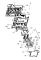
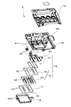
図2及び図3は、上記記録ヘッド3の構成を説明する図であり、図2は記録ヘッド3を斜め上方から観た分解斜視図、図3は記録ヘッド3を斜め下方から観た分解斜視図である。この記録ヘッド3は、上記インクカートリッジ7内のインクをヘッド3内部に導入するインク供給針11が複数配設された供給針ユニット12と、アクチュエータユニット13や流路ユニット14等のヘッド構成部材を有するヘッドユニット15(本発明におけるヘッド本体に相当)と、複数のノズル開口を列設してなるノズル列16を有するノズルプレート17(本発明におけるノズル形成部材の一種)とをヘッドケース18に備えて概略構成される。また、この記録ヘッド3において、ヘッドケース18の先端側には、ヘッドユニット15やノズルプレート17の側部を保護すると共に、ノズルプレート17を接地電位に調整するためのヘッドカバー19が取り付けられるようになっている。
2 and 3 are diagrams for explaining the configuration of the
ヘッドケース18は、上記供給針ユニット12と配線基板20が取り付けられるベース部21と、このベース部21の底部から下方に向けて延出し、開口面にヘッドユニット15が取り付けられる中空箱体状のケース部22とにより構成される部材である。このヘッドケース18と供給針ユニット12の材料としては、例えば、エポキシ系の合成樹脂等が用いられる。
The
ヘッドケース18のベース部21には、配線基板20が配設される基板配設部23が区画されている。配線基板20は、各種駆動信号用の電子部品が実装されると共に、アクチュエータユニット13のフレキシブルケーブル24の一端側端子が接続される接続端子が形成された基板である。また、この配線基板20はコネクタ25を備えており、このコネクタ25には、制御装置からのFFC(フレキシブルフラットケーブル)等の制御ケーブル(何れも図示せず)が電気的に接続されるようになっている。
The
上記ヘッドユニット15は、アクチュエータユニット13と流路ユニット14とから構成されており、これらを重ね合わせた状態で一体化してある。アクチュエータユニット13は、ノズル開口に対応する圧力室を形成した圧力室プレート、連通口を形成した連通口プレート、及び、圧電振動子を実装した振動子プレートを積層した状態で備え、また、TCP(テープキャリアパッケージ)等のフレキシブルケーブル24を、その他端側端子を圧電振動子の端子部に電気的に接続した状態で備えている。このアクチュエータユニット13における圧電振動子は、所謂撓み振動モードの圧電振動子であり、この圧電振動子を駆動、即ち、撓み振動させると、圧力室の容積が変化し、ノズル開口からインク滴(液滴の一種)が吐出されるようになっている。
The
流路ユニット14は、インク供給口30とリザーバの圧力変動を緩和するコンプライアンス部31とを形成した供給口プレート32、及び、インクカートリッジ側から導入されたインクが供給される複数のリザーバ33が形成されたリザーバプレート34により構成されている。供給口プレート32とリザーバプレート34とは、積層した状態で熱溶着フィルム等によって接合されており、リザーバ33からノズル開口に至るまでのインク流路を形成している。そして、このリザーバプレート34の供給口プレート32接合面とは反対側の面、即ち、ヘッドユニット15の底面は、ノズルプレート17が接合される。
The
このノズルプレート17の材料としては、導電性を有する材料、例えばステンレス鋼等の大型の素材基板が用いられる。そして、この素材基板に対してノズル開口の開設や、一方の面(インク滴吐出側の液滴吐出面)に撥液処理が施された後、この素材基板から複数のノズルプレート17が切り出される。したがって、撥液被膜層35は、ノズルプレート17の液滴吐出面のみに形成されるようになっている。
なお、本実施形態におけるノズル形成部材は、ステンレス鋼等の金属基板(素材基板の一種)から構成されたノズルプレート17を例示したが、これに限らず、少なくとも液滴吐出面側が導電性を有する金属基材で構成されたものであれば、どのようなものでもよい。
As the material of the
In addition, although the nozzle formation member in this embodiment illustrated the
撥液被膜層35は、薄膜蒸着技術を用いてフッ素樹脂を含有させた状態でノズルプレート17の液滴吐出面に施される。これにより、撥液性の大幅向上や耐久性の向上に加え、撥液被膜処理の工程の簡略化によるコストダウンができる。
The liquid
上記流路ユニット14における供給口プレート32、リザーバプレート34、上記ノズルプレート17、及び、このノズルプレート17に重畳して取り付けられるヘッドカバー19のフレーム部40には、これらをヘッドケース18に位置決めするための位置決めピン41に挿通可能な位置決め孔42が、この位置決めピン41に対応する位置に夫々2箇所ずつ開設されている。そして、ヘッドユニット15とノズルプレート17は、各々の位置決め孔42に位置決めピン41が挿通することで相対的な位置が合わされた上で、ノズルプレート17を下側にした姿勢でヘッドケース18に固定される。さらに、この位置決めピン41に挿通して位置を合わせた上で、これらのヘッドユニット15とノズルプレート17を外側から包囲するように、ヘッドケース18の先端側にヘッドカバー19が取り付けられる。
In order to position these on the
次にヘッドカバー19について説明する。図4は、上記ヘッドカバー19の構成を説明する図であり、(a)はヘッドカバー19の斜視図、(b)はヘッドカバー19の平面図である。このヘッドカバー19は、ノズルプレート17と同様に、例えば、ステンレス鋼等の導電性を有する金属板で作製されており、中央部分に露出窓部43が開設された額縁状のフレーム部40と、このフレーム部40の外周縁からヘッドケース18側に延出した側壁部44とにより概略構成されている。そして、ノズル列直交方向における両側の側壁部44(図5参照)には、側方に向けて耳片状の止着部45を延出しており、この止着部45には、ヘッドケース18に取り付けるための止着ピン46を挿通する止着孔47が開設されている。また、側壁部44は、プリンタ1側に通じるアースライン(図示せず)に接続されるようになっている。これにより、ヘッドカバー19が接地電位に調整されるように構成されている。
Next, the
ヘッドカバー19の露出窓部43は、上記ノズル列16を露出するように開口した窓枠状の形状をしており、その寸法(内寸)は、ノズルプレート17よりも小さめに設定されている。したがって、ヘッドカバー19をヘッドケース18に取り付けると、ノズルプレート17がこのヘッドカバー19のフレーム部40の一部に重畳する状態で、露出窓部43から露出するようになっている。
The exposed
フレーム部40は略矩形の額縁状に形成されており、このフレーム部40からノズルプレート17の液滴吐出面側に向けて突出した接点突起48が設けられている。そして、この接点突起48が、ヘッドカバー19がヘッドケース18に取り付けられた状態において、ノズルプレート17の液滴吐出面の金属基材部分に当接するようになっている。
The
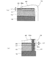
上記の接点突起48の第1の実施形態について説明する。本実施形態における接点突起48aは、ヘッドカバー19の露出窓部43の内周縁に設けられていることを特徴とする。図5は、ヘッドカバー19がヘッドケース18に取り付けられた状態の記録ヘッド3を示す図であり、図6(a)は図5におけるA−A断面図である。
A first embodiment of the contact protrusion 48 will be described. The
図6(a)に示すように、本実施形態の接点突起48aは、ノズルプレート17と接触するフレーム部40の裏面より液体吐出面側に先端が突出した突起であり、特に露出窓部43の内周縁の全周に設けられている。具体的には、接点突起48aの尖った先端は上記フレーム部40の裏面側からノズルプレート17に向けて、例えば、20μm突出している。すなわち、図中のL1=20μmとなる。また、ヘッドカバー19がヘッドケース18に取り付けられた状態において、止着ピン46の取り付け時に止着部45に掛かる面圧が、側壁部44を伝わりフレーム部40にも掛かるので、接点突起48aにもノズルプレート17の液滴吐出面方向に押圧する力が加わる。これにより、ノズルプレート17の液滴吐出面に絶縁性の高い撥液被膜層35が存在する場合においても、接点突起48aが撥液被膜層35を貫通してノズルプレート17の金属基材部分に当接する。したがって、この接点突起48aによって導通をより確実に確保することができる。これにより、ノズルプレート17をヘッドカバー19を介して接地電位に調整することができる。このため、ノズルプレート17の液滴吐出面に撥液性の高い撥液被膜層35を形成したとしても、静電気による駆動回路等の静電破壊や誤作動等の不具合を防止することができる。
As shown in FIG. 6A, the
また、本実施形態によれば、接点突起48aは、ヘッドカバー19の露出窓部43の内周縁の全周に渡って設けられているので、接点突起48aによってヘッドカバー19とノズルプレート17との隙間を塞ぐことができる。このことにより、例えば、ノズル開口から吐出される微小なインク滴がミスト化したものが、ヘッドカバー19の露出窓部43からヘッドカバー19の内部に侵入することを防止することができる。また、このヘッドカバー19とノズルプレート17との隙間に記録紙等の記録媒体を挟み込んでしまうような不具合も防止することができる。
Further, according to the present embodiment, the
なお、この接点突起48aは、露出窓部43を形成する際のプレス加工によって発生するバリを用いて形成してもよい。このようにすれば、このバリと接点突起48aの突出する方向を同一にできるため、新たな加工工程を加えることなく、容易に接点突起48aを形成することができる。
The
次に、上記の接点突起48の第2の実施形態について説明する。本実施形態における接点突起48bは、ヘッドカバー19の位置決め孔42aの内周縁に設けられていることを特徴とする。図6(b)は図5の記録ヘッド3を示す図におけるB−B断面図である。
Next, a second embodiment of the contact protrusion 48 will be described. The
図6(b)に示すように、本実施形態の接点突起48bは、フレーム部40に開設された位置決め孔42aの内周縁からノズルプレート17の液体吐出面側に向けて先端が突出した突起であり、位置決め孔42aの内周縁の全周に設けられている。具体的には、接点突起48bのリング状の先端は上記フレーム部40の裏面側からノズルプレート17に向けて、例えば、20μm突出している。すなわち、図中のL2=20μmとなる。また、ヘッドカバー19がヘッドケース18に取り付けられた状態において、止着ピン46の取り付け時に止着部45に掛かる面圧が、側壁部44を伝わりフレーム部40にも掛かるのに加えて、位置決めピン41のかしめにより掛かる押圧力が位置決め孔42a周辺にも加わるので、接点突起48bにはノズルプレート17の液滴吐出面方向に向けて力が加わる。これにより、ノズルプレート17の液滴吐出面に絶縁性の高い撥液被膜層35が存在する場合においても、接点突起48bが撥液被膜層35を貫通してノズルプレート17の金属基材部分に当接して導通をより確実に確保することができる。したがって、ノズルプレート17をヘッドカバー19を介して接地電位に調整することができる。このため、ノズルプレート17の液滴吐出面に撥液性の高い撥液被膜層35を形成しても、静電気による駆動回路等の静電破壊や誤作動等の不具合を防止することができる。
As shown in FIG. 6B, the
また、本実施形態によれば、接点突起48bは、ヘッドカバー19の位置決め孔42aの内周縁に設けられているので、ヘッドカバー19がヘッドケース18に取り付けられた状態では上述したように液滴吐出面方向に力が加わる。これにより、接点突起48bがノズルプレート17に食い込むことによって、ヘッドカバー19の位置ずれを起こし難い。したがって、ヘッドカバー19を取り付ける際に、位置決めピン41を挿通して位置を合わせられた位置精度を、取り付け後も保持することができる。
Further, according to the present embodiment, the
本実施形態における接点突起48bは、位置決め孔42aを形成する際のパンチ加工によって発生するバリ若しくは膨隆部を用いて形成してもよい。例えば、図7(a)で示すように、ヘッドカバー19に貫通孔(位置決め孔42a)を開けた後に、先の尖ったポンチ50aをその貫通孔に押し込むことによって、そのポンチ50aに倣った形状で接点突起48bを形成することも可能である。
The
また、図7(b)に示すように、例えば、パンチ加工に使用するダイ49側に予め接点突起48bの型を作り、このパンチ加工で貫通孔(位置決め孔42a)を開設する際に、ポンチ50bにより押し出された膨隆部をそのダイ49の型形状に倣った形状にしつつ、位置決め孔42aと接点突起48bとを同時に形成することも可能である。
Further, as shown in FIG. 7B, for example, when a die of the
また、接点突起48は、ヘッドカバー19の露出窓部43の内周縁と位置決め孔42aの内周縁との両方に設けてもよい。
The contact protrusions 48 may be provided on both the inner peripheral edge of the exposed
ところで、本発明は、上記実施形態に限定されるものではなく、特許請求の範囲の記載に基づいて種々の変形が可能である。例えば、ノズルプレート17の液滴吐出面上の接点突起48と当接する領域に、予め紫外線照射などにより撥液被膜層35を除去しておき、接点突起48を当接させてもよい。この場合は、ヘッドカバー取り付け状態においてフレーム部に掛かる面圧や位置決めピンからの押圧等に関係なく、確実に接点突起48をノズルプレート25の液体吐出面の金属基材部分に当接させることができる。
By the way, the present invention is not limited to the above embodiment, and various modifications can be made based on the description of the scope of claims. For example, the contact protrusion 48 may be brought into contact with the liquid
また、接点突起48に関し、上記実施形態においては、フレーム部40の内周縁の全周に設けた例2つを示したが、これには限らない。例えば、フレーム部40の内周縁における少なくとも一部に接点突起48を設けることも可能である。この際、接点突起48とノズルプレート17の液滴吐出面とに導通を確保できさえすれば、接点突起48がどのような形状でも可能である。
Moreover, regarding the contact protrusion 48, in the said embodiment, although two examples provided in the perimeter of the inner periphery of the flame | frame
以上は、液体噴射ヘッドの一種であるインクジェット式記録ヘッド3を例に挙げて説明したが、本発明は他の液体噴射ヘッドにも適用することができる。例えば、液晶ディスプレー等のカラーフィルタの製造に用いられる色材噴射ヘッド、有機EL(Electro Luminescence)ディスプレー、FED(面発光ディスプレー)等の電極形成に用いられる電極材噴射ヘッド、バイオチップ(生物化学素子)の製造に用いられる生体有機物噴射ヘッド等にも本発明を適用することができる。
In the above, the ink
1…プリンタ,2…記録媒体,3…記録ヘッド,4…キャリッジ,5…キャリッジ移動機構,6…プラテンローラ,7…インクカートリッジ,8…タイミングベルト,9…パルスモータ,10…ガイドロッド,11…インク供給針,12…供給針ユニット,13…アクチュエータユニット,14…流路ユニット,15…ヘッドユニット,16…ノズル列,17…ノズルプレート,18…ヘッドケース,19…ヘッドカバー,20…配線基板,21…ベース部,22…ケース部,23…基板配設部,24…フレキシブルケーブル,25…コネクタ,30…インク供給口,31…コンプライアンス部,32…供給口プレート,33…リザーバ,34…リザーバプレート,35…撥液被膜層,40…フレーム部,41…位置決めピン,42…位置決め孔,43…露出窓部,44…側壁部,45…止着部,46…止着ピン,47…止着孔,48…接点突起,49…ダイ,50…ポンチ
DESCRIPTION OF
Claims (3)
前記ノズル開口に連通する圧力室内の液体を液滴として前記ノズル開口から吐出させる圧力発生素子を備えたヘッド本体と、
前記ノズル形成部材及び前記ヘッド本体が固定されるヘッドケースと、
前記液滴吐出面の一部に重畳するように前記ヘッド本体の液滴吐出面側に設けられた金属製のヘッドカバーとを備え、
前記ヘッドカバーは、前記液滴吐出面と重畳するフレーム部から前記ノズル形成部材の液滴吐出面側に向けて突出した接点突起を有し、
該接点突起は、前記ヘッドカバーが前記ヘッドケースに取り付けられた状態において、前記撥液皮膜層を貫通してノズル形成部材の液滴吐出面の金属基材部分に当接することを特徴とする液体噴射ヘッド。 A nozzle forming member in which a plurality of nozzle openings are arranged, and a liquid-repellent coating layer made of an insulating material is formed on a metal substrate on a droplet discharge surface on the droplet discharge side;
A head body including a pressure generating element that discharges the liquid in the pressure chamber communicating with the nozzle opening as droplets from the nozzle opening;
A head case to which the nozzle forming member and the head body are fixed;
A metal head cover provided on the droplet discharge surface side of the head body so as to overlap a part of the droplet discharge surface ;
The head cover has a contact protrusion that protrudes from the frame portion overlapping the droplet discharge surface toward the droplet discharge surface side of the nozzle forming member,
The contact protrusion protrudes through the liquid repellent coating layer and abuts against a metal substrate portion of a droplet discharge surface of a nozzle forming member in a state where the head cover is attached to the head case. head.
前記接点突起は、前記露出窓部の内周縁に設けられていることを特徴とする請求項1に記載の液体噴射ヘッド。 The frame portion is provided with an exposure window portion capable of exposing the nozzle opening in a mounting state on the nozzle forming member.
The liquid ejecting head according to claim 1, wherein the contact protrusion is provided on an inner peripheral edge of the exposed window portion.
前記接点突起は、前記位置決め孔の内周縁に設けられていることを特徴とする請求項1又は請求項2に記載の液体噴射ヘッド。 The frame portion is provided with a positioning hole through which a positioning pin protruding from the head case is inserted,
The liquid ejecting head according to claim 1, wherein the contact protrusion is provided on an inner peripheral edge of the positioning hole.
Priority Applications (3)
| Application Number | Priority Date | Filing Date | Title |
|---|---|---|---|
| JP2004369660A JP4483568B2 (en) | 2004-12-21 | 2004-12-21 | Liquid jet head |
| US11/312,456 US7490923B2 (en) | 2004-12-21 | 2005-12-21 | Liquid ejecting head |
| US12/117,591 US20080235947A1 (en) | 2004-12-21 | 2008-05-08 | Liquid ejecting head |
Applications Claiming Priority (1)
| Application Number | Priority Date | Filing Date | Title |
|---|---|---|---|
| JP2004369660A JP4483568B2 (en) | 2004-12-21 | 2004-12-21 | Liquid jet head |
Publications (3)
| Publication Number | Publication Date |
|---|---|
| JP2006175667A JP2006175667A (en) | 2006-07-06 |
| JP2006175667A5 JP2006175667A5 (en) | 2007-08-30 |
| JP4483568B2 true JP4483568B2 (en) | 2010-06-16 |
Family
ID=36730230
Family Applications (1)
| Application Number | Title | Priority Date | Filing Date |
|---|---|---|---|
| JP2004369660A Expired - Fee Related JP4483568B2 (en) | 2004-12-21 | 2004-12-21 | Liquid jet head |
Country Status (1)
| Country | Link |
|---|---|
| JP (1) | JP4483568B2 (en) |
Families Citing this family (3)
| Publication number | Priority date | Publication date | Assignee | Title |
|---|---|---|---|---|
| JP4941021B2 (en) * | 2007-03-14 | 2012-05-30 | セイコーエプソン株式会社 | Liquid jet head |
| JP2010143004A (en) * | 2008-12-17 | 2010-07-01 | Seiko Epson Corp | Nozzle substrate, liquid droplet delivery head, and liquid droplet delivery device |
| JP5903769B2 (en) * | 2011-03-29 | 2016-04-13 | セイコーエプソン株式会社 | Liquid ejecting head and liquid ejecting apparatus |
-
2004
- 2004-12-21 JP JP2004369660A patent/JP4483568B2/en not_active Expired - Fee Related
Also Published As
| Publication number | Publication date |
|---|---|
| JP2006175667A (en) | 2006-07-06 |
Similar Documents
| Publication | Publication Date | Title |
|---|---|---|
| US7992964B2 (en) | Liquid-jet head apparatus having a fixing plate formed with a protrusion | |
| JP5444866B2 (en) | Liquid discharge head, liquid discharge device, and method of manufacturing liquid discharge head | |
| JP6323654B2 (en) | Liquid ejecting head unit and liquid ejecting apparatus | |
| JP2011025493A (en) | Liquid ejection head, method for manufacturing the same, and liquid ejection device | |
| JP2013169749A (en) | Liquid ejecting head, liquid ejecting apparatus and method of manufacturing the liquid ejecting head | |
| JP2011156845A (en) | Liquid jetting head and method for manufacturing liquid jetting head | |
| JP5018899B2 (en) | Liquid jet head | |
| US8876258B2 (en) | Liquid ejecting head and liquid ejecting apparatus | |
| JP2011201170A (en) | Liquid jetting head and liquid jetting apparatus | |
| JP2006272885A (en) | Liquid jetting head | |
| CN100431840C (en) | Liquid-jet head, liquid-jet apparatus and method for producing liquid-jet head | |
| JP4483568B2 (en) | Liquid jet head | |
| JP2007015356A (en) | Liquid injection head and liquid injection apparatus | |
| JP2007152698A (en) | Liquid jet head and liquid jet apparatus | |
| JP2013169700A (en) | Liquid ejecting head and liquid ejecting apparatus | |
| JP2012200962A (en) | Liquid ejection head, and liquid ejection device | |
| JP5645005B2 (en) | Liquid ejecting head and liquid ejecting apparatus | |
| JP2012161972A (en) | Liquid jet head and liquid jetting apparatus | |
| JP4556562B2 (en) | Liquid jet head | |
| EP3253579B1 (en) | Inkjet head and inkjet printer | |
| JP2006231584A (en) | Liquid jet head | |
| JP4761030B2 (en) | Liquid ejecting head and liquid ejecting apparatus | |
| JP2007062357A (en) | Liquid jetting head | |
| EP3175989B1 (en) | Ink jet head and printer | |
| JP2007054963A (en) | Liquid jetting head |
Legal Events
| Date | Code | Title | Description |
|---|---|---|---|
| A521 | Written amendment |
Free format text: JAPANESE INTERMEDIATE CODE: A523 Effective date: 20070711 |
|
| A621 | Written request for application examination |
Free format text: JAPANESE INTERMEDIATE CODE: A621 Effective date: 20070711 |
|
| TRDD | Decision of grant or rejection written | ||
| A01 | Written decision to grant a patent or to grant a registration (utility model) |
Free format text: JAPANESE INTERMEDIATE CODE: A01 Effective date: 20100302 |
|
| A01 | Written decision to grant a patent or to grant a registration (utility model) |
Free format text: JAPANESE INTERMEDIATE CODE: A01 |
|
| A61 | First payment of annual fees (during grant procedure) |
Free format text: JAPANESE INTERMEDIATE CODE: A61 Effective date: 20100315 |
|
| R150 | Certificate of patent (=grant) or registration of utility model |
Free format text: JAPANESE INTERMEDIATE CODE: R150 |
|
| FPAY | Renewal fee payment (prs date is renewal date of database) |
Free format text: PAYMENT UNTIL: 20130402 Year of fee payment: 3 |
|
| FPAY | Renewal fee payment (prs date is renewal date of database) |
Free format text: PAYMENT UNTIL: 20130402 Year of fee payment: 3 |
|
| FPAY | Renewal fee payment (prs date is renewal date of database) |
Free format text: PAYMENT UNTIL: 20140402 Year of fee payment: 4 |
|
| LAPS | Cancellation because of no payment of annual fees |