JP4483064B2 - Continuous firing furnace - Google Patents
Continuous firing furnace Download PDFInfo
- Publication number
- JP4483064B2 JP4483064B2 JP2000309146A JP2000309146A JP4483064B2 JP 4483064 B2 JP4483064 B2 JP 4483064B2 JP 2000309146 A JP2000309146 A JP 2000309146A JP 2000309146 A JP2000309146 A JP 2000309146A JP 4483064 B2 JP4483064 B2 JP 4483064B2
- Authority
- JP
- Japan
- Prior art keywords
- firing furnace
- tray
- firing
- furnace body
- chamber
- Prior art date
- Legal status (The legal status is an assumption and is not a legal conclusion. Google has not performed a legal analysis and makes no representation as to the accuracy of the status listed.)
- Expired - Lifetime
Links
Images


Description
【0001】
【発明の属する技術分野】
本発明は連続焼成炉に関するものである。
【0002】
【従来の技術】
図7及び図8は従来の連続焼成炉の一例であり、この連続焼成炉は、焼成対象物集合体1を載置したトレー2が通過し得る入側脱気室3と、該入側脱気室3に連なるチャンバ4内に設置され且つ一列に並んだ複数のトレー2が入側脱気室3から順次送り込まれる焼成炉本体5と、チャンバ4に連なり且つ焼成炉本体5を経たトレー2が通過し得る出側脱気室6とを備えている。
【0003】
チャンバ4内側面と焼成炉本体5外側面の間には、断熱材(図示せず)が充填され、また、チャンバ4には、二重壁水冷構造が適用されている。
【0004】
入側脱気室3及び出側脱気室6は、トレー2搬送方向上流側箇所と下流側箇所のそれぞれに昇降可能な扉体7,8,9,10を有している。
【0005】
扉体7,8,9,10を下降位置に設定すると、入側脱気室3、チャンバ4、出側脱気室6の気密が保持される状態になり、扉体7,8,9,10を上昇位置に設定すると、トレー2の通過が許容される状態になる。
【0006】
また、入側脱気室3、焼成炉本体5、並びに出側脱気室6内には、その略全長にわたって左右一対のスキッドビーム11,12,13が、トレー2を下方から摺動可能に支持するように設けられている。
【0007】
焼成炉本体5の長手方向中間部内方には、上下に延びる複数のヒータ14が、トレー2上の焼成対象物集合体1の左右両側に位置するように配置されており、これらのヒータ14によって、焼成対象物集合体1の加熱が図られる。
【0008】
更に、連続焼成炉には、入側脱気室3から焼成炉本体5へトレー2を1つずつ押し込むプッシャ15と、焼成炉本体5から出側脱気室6へトレー2を1つずつ引き出すプラー16とが付帯している。
【0009】
連続焼成炉を稼動させる際には、扉体8,9を閉じた状態で焼成炉本体5内へ無酸化ガスを充填し、ヒータ14を作動させて焼成炉本体5内を、予め設定されている温度に加熱する。
【0010】
次いで、焼成対象物集合体1が載置されているトレー2を入側脱気室3へ搬入し、扉体7を閉じて入側脱気室3内の空気を外部へ排出した後、扉体8を開いたうえ、プッシャ15によってトレー2を焼成炉本体5内へ押し込み、再び扉体8を閉じる。
【0011】
所定時間が経過した後、上述したような手順で、別のトレー2を入側脱気室3から焼成炉本体5内へ押し込み、当該トレー2によって既に入側脱気室3に押し込まれているトレー2を、出側脱気室6へ向かって押し出す。
【0012】
このような作業を繰り返すことにより、トレー2が焼成炉本体5の搬送方向最下流側まで進んだならば、扉体10を閉じた状態で扉体9を開き、プラー16によりトレー2を焼成炉本体5内から出側脱気室6内へ引き出し、更に、扉体9を閉じたうえ、扉体10を開いてトレー2を外部へ取り出す。
【0013】
これにより、焼成対象物集合体1は、焼成炉本体5内の入側脱気室3寄り部分の予熱室17で所定の時間をかけて徐々に昇温され、焼成炉本体5内の中間部分の加熱室18で所定の時間、一定温度に加熱され、更に、焼成炉本体5内の出側脱気室6寄り部分の徐冷室19で所定の時間をかけて徐々に冷却される。
【0014】
【発明が解決しようとする課題】
しかしながら、図7及び図8に示す連続焼成炉は、焼成炉本体5内を縦通するスキッドビーム12でトレー2を支持し、当該トレー2の移動経路の左右両側のヒータ14により焼成対象物集合体1を加熱する構造であるので、上方や左右両側方から焼成対象物集合体1に伝達される入熱量に比べると、下方からトレー2を介して焼成対象物集合体1へ伝達される入熱量が必然的に少なく、焼成対象物集合体1のうち、その下部に位置する焼成対象物の加熱が不充分になり、製品の歩留まりの低下の要因になっている。
【0015】
また、スキッドビーム12の代わりに、当該スキッドビーム12をトレー2の搬送方向へ多数に分割したような短柱部材を用いて、下方から焼成対象物集合体1への入熱量の増加を図ることも考えられる。
【0016】
ところが、プッシャ15によるトレー2押し出し時の水平力に耐え得る強度が短柱部材に確保されるようにするためには、当該短柱部材の断面積を大きくする必要が生じ、その結果、トレー2が短柱部材に接する影の部分が多くなり、輻射加熱効率が向上しない。
【0017】
本発明は上述した実情に鑑みてなしたもので、焼成対象物集合体を均一に加熱可能な連続焼成炉を提供することを目的としている。
【0018】
【課題を解決するための手段】
上記目的を達成するため、本発明の請求項1に記載の連続焼成炉では、焼成対象物集合体を載置した複数のトレーが一端側から他端側へ向かって内部を通過し得るように略水平に設置した焼成炉本体と、該焼成炉本体内にその略全長にわたり間隔をおいて枢支され且つ前記のトレーを下方から支持する多数のフリーローラと、焼成炉本体内の所定範囲にわたりフリーローラ間下方に位置するように配置した複数の下部ヒータと、焼成炉本体内の所定範囲にわたり焼成対象物集合体の通過経路上方に位置するように配置した複数の上部ヒータとを備え、下部ヒータ及び上部ヒータを、トレー幅方向に略水平に延びて焼成炉本体の左右壁部を貫通する加熱用通電体と、該加熱用通電体の両端に設けた電極部を変位可能に支持するホルダとで構成し、前記ホルダを、焼成炉本体の左右壁部に該壁部内方に連通するように設けた支持筒と、該支持筒の端部に締結され且つ前記電極部を周方向に取り囲む環状の支持座と、該支持座と電極部の間に介在するシールリングとで構成している。
【0019】
本発明の請求項2に記載の連続焼成炉では、前記電極部の素材に、銅を用いている。本発明の請求項3に記載の連続焼成炉では、前記電極部の内部に、冷却水が連続的に送給される流路を形成している。
【0020】
本発明の請求項4に記載の連続焼成炉では、焼成炉本体内の略全長にわたり間隔をおいて枢支される多数のフリーローラの列を、トレー幅方向へ複数条並べて配置している。
【0021】
本発明の請求項5に記載の連続焼成炉では、下部ヒータ及び上部ヒータの双方を、トレー幅方向に略水平に且つトレー通過方向から見て左右対称に配置している。
【0022】
本発明の請求項1乃至請求項5に記載の連続焼成炉のいずれにおいても、上部ヒータによる輻射熱エネルギーを、焼成対象物集合体にその上側から伝達させ、また、下部ヒータによる輻射熱エネルギーを、フリーローラ間の空隙、並びにトレーを介して焼成対象物集合体にその下側から伝達させて、焼成対象物集合体を加熱する。更に、加熱用通電体を焼成炉本体の左右壁部に貫通させ、また、当該加熱用通電体の両端の電極部をホルダに変位可能に支持させて、加熱用通電体と焼成炉本体との熱膨張差を吸収する。
【0023】
本発明の請求項3に記載の連続焼成炉においては、電極部の内部の流路に、冷却水を連続的に送給する。
【0024】
本発明の請求項4に記載の連続焼成炉においては、トレー幅方向に並ぶ複数条のフリーローラの列によりトレーを支持させ、下部ヒータから焼成対象物集合体への輻射熱エネルギーの伝達効率の向上を図る。
【0025】
本発明の請求項5に記載の連続焼成炉においては、下部ヒータ及び上部ヒータをトレー幅方向へ略水平に且つ左右対称に配置して、焼成対象物集合体の幅方向の温度分布の均一化を図る。
【0026】
【発明の実施の形態】
以下、本発明の実施の形態を、図示例とともに説明する。
【0027】
図1乃至図5は本発明の連続焼成炉の実施の形態の一例を示すもので、図中、図7及び図8と同一の符号を付した部分は同一物を表わしている。
【0028】
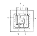
この連続焼成炉は、トレー22が通過し得る入側脱気室23と、該入側脱気室23に連なるチャンバ24内に設置され且つ複数のトレー22が入側脱気室23から順次送り込まれる焼成炉本体25と、チャンバ24に連なり且つ焼成炉本体25を経たトレー22が通過し得る出側脱気室26と、前記の焼成炉本体25の略全長、並びにチャンバ24のトレー22搬送方向下流端寄り部分にわたってトレー22の下面に接するように枢支した多数のフリーローラ32と、焼成炉本体25内の所定範囲にわたりフリーローラ32間下方に位置するように配置した複数の下部ヒータ34と、焼成炉本体25内の所定範囲にわたり焼成対象物集合体1の通過経路上方に位置するように配置した複数の上部ヒータ44とを備えている。
【0029】
トレー22の上面には、2組の焼成対象物集合体1を幅方向に並べて載置することができ、また、トレー22の下面は平滑に形成されている。
【0030】
チャンバ24内側面と焼成炉本体25外側面の間には、断熱材(図示せず)が充填され、チャンバ24には、二重壁水冷構造が適用されている。
【0031】
焼成炉本体25は、焼成対象物入口端が入側脱気室23に隣接し、焼成対象物出口端が出側脱気室26に対して所定距離を隔てており、焼成対象物入口端寄り部分及び出口端寄り部分の開口断面積が中間部分よりも小さく形成されている。
【0032】
この焼成炉本体25の素材には、耐熱性に優れた黒鉛を用いている。
【0033】
入側脱気室23及び出側脱気室26は、トレー22搬送方向上流側箇所と下流側箇所のそれぞれに昇降可能な扉体27,28,29,30を有している。
【0034】
これら扉体27,28,29,30を下降位置に設定すると、入側脱気室23、チャンバ24、出側脱気室26の気密が保持される状態に、また扉体27,28,29,30を上昇位置に設定すると、トレー22の通過が許容される状態になる。
【0035】
フリーローラ32は、焼成炉本体25の内底面などに立設した支柱32a上端部のブラケット32bに枢支されている。
【0036】
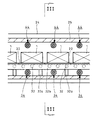
このフリーローラ32の列は、トレー22下面の幅方向一側寄り部分、幅方向中央部分、幅方向他側寄り部分のそれぞれにフリーローラ32が接するように、トレー22幅方向に3条並べて配置されている。
【0037】
また、入側脱気室23、及び出側脱気室26内には、フリーローラ31,33が、上述したフリーローラ32と同様な枢支構造でトレー22下面に接するように配置されている。
【0038】
下部ヒータ34と上部ヒータ44は、焼成炉本体25の中間部分(開口断面積が大きい部分)に配置されており、当該ヒータ34,44への通電により、焼成対象物集合体1の加熱が図られる。
【0039】
これらのヒータ34,44は、トレー22の幅方向に略水平に延び且つ焼成炉本体25の左右壁部を貫通する加熱用通電体34a,44aと、該加熱用通電体34a,44a両端に設けた電極部34b,44bを支持するホルダ54,64とで構成されている。
【0040】
上記の加熱用通電体34a,44aの素材には、耐熱性に優れた黒鉛を用いている。
【0041】
電極部34b,44bの素材には、銅を用いており、電極部34b,44bの内部には、冷却水が連続的に送給される流路(図示せず)が形成されている。
【0042】
ホルダ54,64は、チャンバ24の左右壁部に該壁部内方に連通するように設けた支持筒54a,64aと、該支持筒54a,64aの端部に締結され且つ前記の電極部34b,44bを周方向に取り囲む環状の支持座54b,64bと、該支持座54b,64bと電極部34b,44bの間に介在するシールリング54c,64cとを有しており、当該シールリング54c,64cを中心とする電極部34b,44bの揺動が許容されるようになっている。
【0043】
これに加えて、連続焼成炉には、入側脱気室23から焼成炉本体25へトレー22を1つずつ押し込むプッシャ35と、焼成炉本体25から出側脱気室26へトレー22を1つずつ引き出すプラー36と、チャンバ24の出側脱気室26に隣接する部分内の無酸化性ガスを撹拌するためのファン21とが付帯している。
【0044】
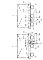
プッシャ35及びプラー36は、上方へ突出する支持部35a,36aを有し且つトレー22搬送経路に平行に前後移動し得るアーム35b,36bと、前記の支持部35a,36aにトレー22幅方向に水平に延びるピン35c,36cを介して枢支されたドック35d,36dと、当該ドック35d,36dの回動範囲を規制するように支持部35a,36aに固着したストッパ35e,36eとで構成され、トレー22の通過経路の下方に設置されている。
【0045】
ドック35d,36dは、それぞれのトレー22の同一箇所に穿設されている角孔22aの前縁部分に当接する押圧面35f,36fと、トレー22の下面に案内される摺動面35g,36gとを有しており、前記のアーム35b,36bをトレー22搬送方向上流側へ移動させると、トレー22の下面で摺動面35g,36gが案内されて傾動した状態になった後、ドック35d,36dの上端部が角孔22aに嵌合する。
【0046】
また逆に、アーム35b,36bをトレー22搬送方向下流側へ移動させると、ドック35d,36dがその自重により押圧面35f,36fが角孔22aの前縁部分に当接する方向へ回動するとともに、ストッパ35e,36eでドック35d,36dの回動が規制され、これにより、アーム35b,36bの移動に応じてトレー22が搬送方向下流側へ向かって押圧される。
【0047】
連続焼成炉を稼動させるときには、扉体28,29を閉じた状態で焼成炉本体25内へ無酸化ガスを充填し、下部ヒータ34と上部ヒータ44とを作動させて焼成炉本体25内を、予め設定されている温度に加熱し、これに加えて、ファン21を作動させておく。
【0048】
次いで、焼成対象物集合体1が載置されているトレー22を入側脱気室23へ搬入し、扉体27を閉じて入側脱気室23内の空気を外部へ排出し、扉体28を開いたうえ、プッシャ35によってトレー22を焼成炉本体25内へ押し込み、再び扉体28を閉じる。
【0049】
所定時間が経過した後、上述したような手順で、別のトレー22を入側脱気室23から焼成炉本体25内へ押し込み、当該トレー22によって既に焼成炉本体25に押し込まれているトレー22を、出側脱気室26へ向かって押し出す。
【0050】
このような作業を繰り返すことで、トレー22がチャンバ24の搬送方向最下流側まで進んだならば、扉体30を閉じた状態で扉体29を開き、プラー36によりトレー22をチャンバ24内から出側脱気室26内へ引き出し、更に、扉体29を閉じたうえ、扉体30を開いてトレー22を外部へ取り出す。
【0051】
これにより、焼成対象物集合体1は、焼成炉本体25内の入側脱気室23寄り部分の予熱室37で所定の時間をかけて徐々に昇温され、次に、焼成炉本体25内の中間部分の加熱室38で所定の時間、一定温度に加熱された後、焼成炉本体25内の出側脱気室26寄り部分の徐冷室39、及びファン21が取り付けられているチャンバ24の出側脱気室26に隣接した冷却室40で所定の時間をかけて徐々に冷却される。
【0052】
図6は、焼成対象物集合体1の所定箇所A,B,C,D及び焼成炉本体25の内側壁面所定箇所Eの温度と焼成時間との関係を示すグラフであり、このグラフからは、焼成開始から約4時間20分程度経過すると、各箇所A,B,C,D,Eの温度差が微小(実測値で約6℃程度)になり、焼成対象物集合体1が均一に加熱されることが把握できる。
【0053】
すなわち、図1乃至図5に示す連続焼成炉では、上部ヒータ44による輻射熱エネルギーを、焼成対象物集合体1にその上側から伝達させ、下部ヒータ34による輻射熱エネルギーを、フリーローラ32間の空隙、及びトレー22を介して焼成対象物集合体1にその下側から伝達させるので、互いに独立した上部ヒータ44と下部ヒータ34とを適宜制御することにより、当該焼成対象物集合体1に対する上方からの入熱量と下方からの入熱量の差を小さくすることができ、焼成対象物集合体1のうち、その下部に位置する焼成対象物も充分に加熱され、製品の歩留まりが向上する。
【0054】
また、トレー22幅方向に並ぶ複数条のフリーローラ32の列によってトレー22を支持するので、その下面がフリーローラ32に接する影の部分が少なく、下部ヒータ34から焼成対象物集合体1への輻射熱エネルギーの伝達効率の向上を図ることができる。
【0055】
更に、下部ヒータ34及び上部ヒータ44をトレー22幅方向へ略水平に且つ左右対称に配置しているので、焼成対象物集合体1の幅方向の温度分布の均一化を図ることができる。
【0056】
これに加えて、各加熱用通電体34a,44aを焼成炉本体25の左右壁部に貫通させ且つその両端の電極部34b,44bをホルダ54,64に変位可能に支持させているので、各ヒータ34,44と焼成炉本体25との熱膨張差を吸収することができる。
【0057】
なお、本発明の連続焼成炉は、上述した実施の形態のみに限定されるものではなく、本発明の要旨を逸脱しない範囲において変更を加え得ることは勿論である。
【0058】
【発明の効果】
以上述べたように、本発明の連続焼成炉によれば、下記のような種々の優れた効果を奏し得る。
【0059】
(1)本発明の請求項1乃至請求項5に記載の連続焼成炉のいずれにおいても、上部ヒータによる輻射熱エネルギーを、焼成対象物集合体にその上側から伝達させ、また、下部ヒータによる輻射熱エネルギーを、フリーローラ間の空隙、並びにトレーを介して焼成対象物集合体にその下側から伝達させるので、焼成対象物集合体に対する上方からの入熱量と下方からの入熱量の差を小さくすることができ、焼成対象物集合体の下部に位置する焼成対象物も充分に加熱され、製品の歩留まりが向上する。更に、加熱用通電体を焼成炉本体の左右壁部に貫通させ、また、当該加熱用通電体の両端の電極部をホルダに変位可能に支持させるので、加熱用通電体と焼成炉本体の熱膨張差を吸収することができる。
【0060】
(2)本発明の請求項4に記載の連続焼成炉においては、トレー幅方向に並ぶ複数条のフリーローラの列によりトレーを支持するので、下部ヒータから焼成対象物集合体への輻射熱エネルギーの伝達効率の向上を図ることができる。
【0061】
(3)本発明の請求項5に記載の連続焼成炉においては、下部ヒータ及び上部ヒータをトレー幅方向へ略水平に且つ左右対称に配置しているので、焼成対象物集合体の幅方向の温度分布の均一化を図ることができる。
【図面の簡単な説明】
【図1】本発明の連続焼成炉の実施の形態の一例を概念的に示す全体縦断面図である。
【図2】図1における焼成炉本体の主要部分を概念的に示す縦断面図である。
【図3】図2のIII−III矢視図である。
【図4】図1におけるプッシャの構造を概念的に示す側面図である。
【図5】図1におけるプラーの構造を概念的に示す側面図である。
【図6】焼成対象物集合体の所定箇所及び焼成炉本体の内側壁面所定箇所の温度と焼成時間との関係を示すグラフである。
【図7】従来の連続焼成炉の一例を概念的に示す全体縦断面図である。
【図8】図7における焼成炉本体の主要部分を概念的に示す横断面図である。
【符号の説明】
1 焼成対象物集合体
22 トレー
25 焼成炉本体
32 フリーローラ
34 下部ヒータ
34a 加熱用通電体
34b 電極部
44 上部ヒータ
44a 加熱用通電体
44b 電極部
54 ホルダ
64 ホルダ[0001]
BACKGROUND OF THE INVENTION
The present invention relates to a continuous firing furnace.
[0002]
[Prior art]
FIGS. 7 and 8 show an example of a conventional continuous firing furnace. The continuous firing furnace includes an inlet-
[0003]
A space between the inner surface of the chamber 4 and the outer surface of the firing furnace
[0004]
The inlet-
[0005]
When the
[0006]
A pair of left and right
[0007]
A plurality of
[0008]
Further, in the continuous firing furnace, a
[0009]
When the continuous firing furnace is operated, a non-oxidizing gas is filled into the
[0010]
Next, the
[0011]
After a predetermined time has passed, another
[0012]
By repeating such operations, when the
[0013]
Thereby, the
[0014]
[Problems to be solved by the invention]
However, in the continuous firing furnace shown in FIGS. 7 and 8, the
[0015]
Further, instead of the
[0016]
However, in order to ensure that the short column member has sufficient strength to withstand the horizontal force when the
[0017]
This invention is made | formed in view of the situation mentioned above, and it aims at providing the continuous baking furnace which can heat a baking target object aggregate | assembly uniformly.
[0018]
[Means for Solving the Problems]
In order to achieve the above object, in the continuous firing furnace according to
[0019]
In the continuous firing furnace according to
[0020]
In the continuous firing furnace according to claim 4 of the present invention, a plurality of rows of free rollers that are pivotally supported at substantially the entire length in the firing furnace main body are arranged in a row in the tray width direction.
[0021]
In the continuous firing furnace according to the fifth aspect of the present invention, both the lower heater and the upper heater are arranged substantially horizontally in the tray width direction and symmetrically when viewed from the tray passing direction.
[0022]
In any of the continuous firing furnaces according to
[0023]
In the continuous firing furnace according to
[0024]
In the continuous firing furnace according to claim 4 of the present invention, the tray is supported by a row of a plurality of free rollers arranged in the tray width direction, and the transmission efficiency of radiant heat energy from the lower heater to the firing object aggregate is improved. Plan.
[0025]
In the continuous firing furnace according to
[0026]
DETAILED DESCRIPTION OF THE INVENTION
Hereinafter, embodiments of the present invention will be described with reference to the drawings.
[0027]
1 to 5 show an example of an embodiment of a continuous firing furnace according to the present invention. In the figure, the same reference numerals as those in FIGS. 7 and 8 denote the same parts.
[0028]
This continuous firing furnace is installed in an inlet
[0029]
Two sets of firing
[0030]
A heat insulating material (not shown) is filled between the inner surface of the
[0031]
The firing
[0032]
As the material of the firing
[0033]
The inlet-
[0034]
When these
[0035]
The
[0036]
The rows of the
[0037]
Moreover, in the entrance
[0038]
The
[0039]
These
[0040]
As the material for the heating
[0041]
Copper is used as a material for the
[0042]
The
[0043]
In addition to this, in the continuous firing furnace, a
[0044]
The
[0045]
The
[0046]
On the other hand, when the
[0047]
When the continuous firing furnace is operated, the firing furnace
[0048]
Next, the
[0049]
After a predetermined time has passed, another
[0050]
By repeating such operations, when the
[0051]
Thereby, the firing
[0052]
FIG. 6 is a graph showing the relationship between the temperature and the firing time of the predetermined locations A, B, C, D of the
[0053]
That is, in the continuous firing furnace shown in FIGS. 1 to 5, the radiant heat energy by the
[0054]
In addition, since the
[0055]
Furthermore, since the
[0056]
In addition to this, since each heating current-carrying
[0057]
In addition, the continuous baking furnace of this invention is not limited only to embodiment mentioned above, Of course, it can add in the range which does not deviate from the summary of this invention.
[0058]
【The invention's effect】
As described above, according to the continuous firing furnace of the present invention, the following various excellent effects can be achieved.
[0059]
(1) In any of the continuous firing furnaces according to
[0060]
(2) In the continuous firing furnace according to claim 4 of the present invention, the tray is supported by a row of a plurality of free rollers arranged in the tray width direction, so that the radiant heat energy from the lower heater to the fired object aggregate is reduced. The transmission efficiency can be improved.
[0061]
(3) In the continuous firing furnace according to
[Brief description of the drawings]
FIG. 1 is an overall longitudinal sectional view conceptually showing an example of an embodiment of a continuous firing furnace of the present invention.
2 is a longitudinal sectional view conceptually showing a main part of a firing furnace body in FIG. 1. FIG.
FIG. 3 is a view taken in the direction of arrows III-III in FIG. 2;
4 is a side view conceptually showing the structure of the pusher in FIG. 1. FIG.
5 is a side view conceptually showing the structure of the puller in FIG. 1. FIG.
FIG. 6 is a graph showing the relationship between the temperature and the firing time at a predetermined location on the firing object aggregate and a predetermined location on the inner wall surface of the firing furnace main body.
FIG. 7 is an overall longitudinal sectional view conceptually showing an example of a conventional continuous firing furnace.
8 is a cross-sectional view conceptually showing the main part of the firing furnace main body in FIG. 7. FIG.
[Explanation of symbols]
1 Firing
Claims (5)
Priority Applications (11)
| Application Number | Priority Date | Filing Date | Title |
|---|---|---|---|
| JP2000309146A JP4483064B2 (en) | 2000-10-10 | 2000-10-10 | Continuous firing furnace |
| TW090123641A TW500910B (en) | 2000-10-10 | 2001-09-25 | Continuous sintering furnace and its using method |
| KR1020010061751A KR100619463B1 (en) | 2000-10-10 | 2001-10-08 | Continuous sintering furnace and use thereof |
| CA002358434A CA2358434C (en) | 2000-10-10 | 2001-10-09 | Continuous sintering furnace and use thereof |
| US09/972,933 US6530780B2 (en) | 2000-10-10 | 2001-10-10 | Continuous sintering furnace and use thereof |
| ES06076759T ES2428144T3 (en) | 2000-10-10 | 2001-10-10 | Continuous sintering furnace and use thereof |
| CNB011354054A CN100397020C (en) | 2000-10-10 | 2001-10-10 | Continuous firing furnace and its use method |
| EP01308641A EP1197720B1 (en) | 2000-10-10 | 2001-10-10 | Continuous sintering furnace and use thereof |
| EP06076759.7A EP1780487B1 (en) | 2000-10-10 | 2001-10-10 | Continuous sintering furnace and use thereof |
| DE60133520T DE60133520T2 (en) | 2000-10-10 | 2001-10-10 | Continuous sintering furnace and use thereof |
| ES01308641T ES2300308T3 (en) | 2000-10-10 | 2001-10-10 | CONTINUOUS SINTERIZATION OVEN AND ITS USE. |
Applications Claiming Priority (1)
| Application Number | Priority Date | Filing Date | Title |
|---|---|---|---|
| JP2000309146A JP4483064B2 (en) | 2000-10-10 | 2000-10-10 | Continuous firing furnace |
Publications (2)
| Publication Number | Publication Date |
|---|---|
| JP2002115976A JP2002115976A (en) | 2002-04-19 |
| JP4483064B2 true JP4483064B2 (en) | 2010-06-16 |
Family
ID=18789359
Family Applications (1)
| Application Number | Title | Priority Date | Filing Date |
|---|---|---|---|
| JP2000309146A Expired - Lifetime JP4483064B2 (en) | 2000-10-10 | 2000-10-10 | Continuous firing furnace |
Country Status (1)
| Country | Link |
|---|---|
| JP (1) | JP4483064B2 (en) |
Families Citing this family (2)
| Publication number | Priority date | Publication date | Assignee | Title |
|---|---|---|---|---|
| JP7377760B2 (en) * | 2020-03-31 | 2023-11-10 | 株式会社ノリタケカンパニーリミテド | Continuous firing furnace and continuous firing method for powder materials |
| JP7301016B2 (en) * | 2020-03-31 | 2023-06-30 | 株式会社ノリタケカンパニーリミテド | Continuous firing furnace |
-
2000
- 2000-10-10 JP JP2000309146A patent/JP4483064B2/en not_active Expired - Lifetime
Also Published As
| Publication number | Publication date |
|---|---|
| JP2002115976A (en) | 2002-04-19 |
Similar Documents
| Publication | Publication Date | Title |
|---|---|---|
| CA2358434C (en) | Continuous sintering furnace and use thereof | |
| US4373702A (en) | Jet impingement/radiant heating apparatus | |
| US3677234A (en) | Heating apparatus and process | |
| CN1596666B (en) | Convection oven and related air flow system | |
| KR101796268B1 (en) | Baking device and oven | |
| US8766148B2 (en) | Baking oven having inductors and susceptor plates | |
| JP5451702B2 (en) | Cooking oven for bakery, pastry shop, cake shop products, or similar products | |
| CN106455584A (en) | Baking oven | |
| CA2714468A1 (en) | Baking oven | |
| JP4483064B2 (en) | Continuous firing furnace | |
| US6129258A (en) | Muffle convection brazing and annealing system and method | |
| US4738705A (en) | Gas burner forced convection heating of glass sheets | |
| JP4472854B2 (en) | Continuous firing furnace and method of using the same | |
| US4444558A (en) | System for heating broadwise-end portions of metal material | |
| NL1010003C2 (en) | Reactor equipped with heating. | |
| US5787800A (en) | Oven and method for baking moldings by means of air heating | |
| JPH0582450B2 (en) | ||
| JPS6144127A (en) | Uniformly heating device for metal material in motion | |
| NL2004883C2 (en) | Annealing installation with m-shaped strip treatment tunnel. | |
| JP2608064B2 (en) | Glass sheet heating apparatus and glass sheet heating method | |
| US3854918A (en) | Method for continuous heat treating of glass articles | |
| KR101903179B1 (en) | Continuous annealing furnace | |
| US4781172A (en) | Variable flow multiple pass apparatus for heating liquids | |
| JP4587022B2 (en) | Continuous firing furnace and continuous firing method | |
| JP4479100B2 (en) | Continuous heat treatment furnace for metal strip |
Legal Events
| Date | Code | Title | Description |
|---|---|---|---|
| A621 | Written request for application examination |
Free format text: JAPANESE INTERMEDIATE CODE: A621 Effective date: 20070905 |
|
| A977 | Report on retrieval |
Free format text: JAPANESE INTERMEDIATE CODE: A971007 Effective date: 20090304 |
|
| A131 | Notification of reasons for refusal |
Free format text: JAPANESE INTERMEDIATE CODE: A131 Effective date: 20090317 |
|
| A521 | Written amendment |
Free format text: JAPANESE INTERMEDIATE CODE: A523 Effective date: 20090515 |
|
| RD02 | Notification of acceptance of power of attorney |
Free format text: JAPANESE INTERMEDIATE CODE: A7422 Effective date: 20090515 |
|
| A131 | Notification of reasons for refusal |
Free format text: JAPANESE INTERMEDIATE CODE: A131 Effective date: 20091215 |
|
| A521 | Written amendment |
Free format text: JAPANESE INTERMEDIATE CODE: A523 Effective date: 20100204 |
|
| TRDD | Decision of grant or rejection written | ||
| A01 | Written decision to grant a patent or to grant a registration (utility model) |
Free format text: JAPANESE INTERMEDIATE CODE: A01 Effective date: 20100302 |
|
| A01 | Written decision to grant a patent or to grant a registration (utility model) |
Free format text: JAPANESE INTERMEDIATE CODE: A01 |
|
| A61 | First payment of annual fees (during grant procedure) |
Free format text: JAPANESE INTERMEDIATE CODE: A61 Effective date: 20100315 |
|
| R151 | Written notification of patent or utility model registration |
Ref document number: 4483064 Country of ref document: JP Free format text: JAPANESE INTERMEDIATE CODE: R151 |
|
| FPAY | Renewal fee payment (event date is renewal date of database) |
Free format text: PAYMENT UNTIL: 20130402 Year of fee payment: 3 |
|
| FPAY | Renewal fee payment (event date is renewal date of database) |
Free format text: PAYMENT UNTIL: 20140402 Year of fee payment: 4 |
|
| R250 | Receipt of annual fees |
Free format text: JAPANESE INTERMEDIATE CODE: R250 |
|
| R250 | Receipt of annual fees |
Free format text: JAPANESE INTERMEDIATE CODE: R250 |