JP4482811B2 - Recording apparatus and method - Google Patents
Recording apparatus and method Download PDFInfo
- Publication number
- JP4482811B2 JP4482811B2 JP2005064630A JP2005064630A JP4482811B2 JP 4482811 B2 JP4482811 B2 JP 4482811B2 JP 2005064630 A JP2005064630 A JP 2005064630A JP 2005064630 A JP2005064630 A JP 2005064630A JP 4482811 B2 JP4482811 B2 JP 4482811B2
- Authority
- JP
- Japan
- Prior art keywords
- data
- history
- encoding
- picture
- stream
- Prior art date
- Legal status (The legal status is an assumption and is not a legal conclusion. Google has not performed a legal analysis and makes no representation as to the accuracy of the status listed.)
- Expired - Fee Related
Links
Images


Description
本発明は、コーディングシステム及び方法、符号化装置および方法、復号化装置及び方法、記録装置及び方法、ならびに再生装置及び方法に関し、特に、MPEG規格に基づいて過去に符号化処理が施されたことがある符号化ストリームに対して再符号化処理を施すことによって、異なるGOP(Group of Pictures)構造や異なるビットレートを有した再符号化ストリームを生成するためのトランスコーダに用いて好適なコーディングシステム及び方法、符号化装置および方法、復号化装置及び方法、記録装置及び方法、ならびに再生装置及び方法に関する。 The present invention relates to a coding system and method, an encoding device and method, a decoding device and method, a recording device and method, and a playback device and method, and in particular, encoding processing has been performed in the past based on the MPEG standard. A coding system suitable for use in a transcoder for generating a re-encoded stream having a different GOP (Group of Pictures) structure and a different bit rate by performing re-encoding processing on a certain encoded stream And a coding apparatus and method, a decoding apparatus and method, a recording apparatus and method, and a reproduction apparatus and method.
近年、テレビジョンプログラムを制作及び放送する放送局においては、ビデオデータを圧縮/符号化処理するために、MPEG(Moving Picture Experts Group)技術が一般的に使われるようになってきた。特に、ビデオデータをテープなどのランダムアクセス可能な記録媒体素材に記録する場合、及びビデオデータをケーブルや衛星を介して伝送する場合には、このMPEG技術がデファクトスタンダードになりつつある。 In recent years, MPEG (Moving Picture Experts Group) technology has been commonly used in broadcasting stations that produce and broadcast television programs in order to compress / encode video data. In particular, this MPEG technology is becoming the de facto standard when recording video data on a randomly accessible recording medium material such as a tape and when transmitting video data via a cable or satellite.
放送局において制作されたビデオプログラムが各家庭に伝送されるまでの放送局における処理の一例を簡単に説明する。まず、ビデオカメラとVTR(Video Tape Recorder)が一体となったカムコーダに設けられたエンコーダによって、ソースビデオデータをエンコード処理して磁気テープ上に記録する。この際、カムコーダのエンコーダは、VTRのテープの記録フォーマットに適するように、ソースビデオデータを符号化する。たとえば、この磁気テープ上に記録されるMPEGビットストリームのGOP構造は、2フレームから1GOPが構成される構造(たとえば、I,B,I,B,I,B,……)とされる。また磁気テープ上に記録されているMPEGビットストリームのビットレートは、18Mbpsである。 An example of processing in the broadcasting station until the video program produced in the broadcasting station is transmitted to each home will be briefly described. First, source video data is encoded and recorded on a magnetic tape by an encoder provided in a camcorder in which a video camera and a VTR (Video Tape Recorder) are integrated. At this time, the encoder of the camcorder encodes the source video data so as to be suitable for the recording format of the VTR tape. For example, the GOP structure of an MPEG bit stream recorded on the magnetic tape is a structure (for example, I, B, I, B, I, B,...) That consists of two frames and one GOP. The bit rate of the MPEG bit stream recorded on the magnetic tape is 18 Mbps.
次に、メイン放送局において、この磁気テープ上に記録されたビデオビットストリームを編集する編集処理を行う。そのために、磁気テープ上に記録されたビデオビットストリームのGOP構造を、編集処理に適したGOP構造に変換する。編集処理に適したGOP構造とは、1GOPが1フレームから構成され、すべてのピクチャがIピクチャであるGOP構造である。なぜなら、フレーム単位で編集を行うためには、他のピクチャと相関のないIピクチャがもっとも適しているからである。実際のオペレーションとしては、磁気テープ上に記録されたビデオストリームを一旦デコードしてベースバンドのビデオデータに戻す。そして、そのベースバンドのビデオ信号を、すべてのピクチャがIピクチャとなるように再エンコードする。このようにデコード処理及び再エンコード処理を行うことによって、編集処理に適したGOP構造を有したビットストリームを生成することができる。 Next, in the main broadcasting station, editing processing for editing the video bit stream recorded on the magnetic tape is performed. For this purpose, the GOP structure of the video bit stream recorded on the magnetic tape is converted into a GOP structure suitable for editing processing. A GOP structure suitable for editing processing is a GOP structure in which one GOP is composed of one frame and all pictures are I pictures. This is because an I picture having no correlation with other pictures is most suitable for editing in frame units. In actual operation, the video stream recorded on the magnetic tape is once decoded and returned to the baseband video data. Then, the baseband video signal is re-encoded so that all pictures become I pictures. By performing the decoding process and the re-encoding process in this way, it is possible to generate a bitstream having a GOP structure suitable for the editing process.
次に、上述した編集処理によって生成された編集ビデオプログラムを、メイン局から地方局に伝送するために、編集ビデオプログラムのビットストリームを、伝送処理に適したGOP構造及びビットレートに変換する。放送局間の伝送に適したGOP構造とは、たとえば、1GOPが15フレームから構成されているGOP構造(たとえば、I,B,B,P,B,B,P……)である。また、放送局間の伝送に適したビットレートは、一般的に放送局間においては、光ファイバなどの高伝送容量を有した専用線が設けらてれいるので、50Mbps以上のハイビットレートであることが望ましい。具体的には、編集処理されたビデオプログラムのビットストリームを一旦デコードしてベースバンドのビデオデータに戻す。そして、そのベースバンドのビデオデータを上述した放送局間の伝送に適したGOP構造及びビットレートを有するように再エンコードする。 Next, in order to transmit the edited video program generated by the editing process described above to the local station from the main station, the bit stream of the edited video program is converted into a GOP structure and a bit rate suitable for the transmission process. A GOP structure suitable for transmission between broadcasting stations is, for example, a GOP structure (for example, I, B, B, P, B, B, P...) In which 1 GOP is composed of 15 frames. The bit rate suitable for transmission between broadcasting stations is generally a high bit rate of 50 Mbps or more because a dedicated line having a high transmission capacity such as an optical fiber is provided between broadcasting stations. It is desirable. Specifically, the bit stream of the edited video program is once decoded and returned to baseband video data. Then, the baseband video data is re-encoded so as to have a GOP structure and a bit rate suitable for transmission between the broadcasting stations described above.
地方局においては、メイン局から伝送されてきたビデオプログラムの中に、地方特有のコマーシャルを挿入するために編集処理が行われる。つまり、上述した編集処理と同じように、メイン局から伝送されてきたビデオストリームを一旦デコードしてベースバンドのビデオデータに戻す。そして、そのベースバンドのビデオ信号を、すべてのピクチャがIピクチャとなるように再エンコードすることによって、編集処理に適したGOP構造を有したビットストリームを生成することができる。 In the local station, editing processing is performed in order to insert a commercial unique to the local area in the video program transmitted from the main station. That is, as in the editing process described above, the video stream transmitted from the main station is once decoded and returned to the baseband video data. Then, by re-encoding the baseband video signal so that all the pictures become I pictures, a bitstream having a GOP structure suitable for editing processing can be generated.
続いて、この地方局において編集処理が行われたビデオプログラムを各家庭に、ケーブルや衛星を介して伝送するために、この伝送処理に適したGOP構造及びビットレートに変換する。たとえば、各家庭に伝送するための伝送処理に適したGOP構造とは、1GOPが15フレームから構成されるGOP構造(たとえば、I,B,B,P,B,B,P……)であって、各家庭に伝送するための伝送処理に適したビットレートは、5Mbps程度の低ビットレートである。具体的には、編集処理されたビデオプログラムのビットストリームを一旦デコードしてベースバンドのビデオデータに戻す。そして、そのベースバンドのビデオデータを上述した伝送処理に適したGOP構造及びビットレートを有するように再エンコードする。 Subsequently, the video program edited in the local station is converted into a GOP structure and bit rate suitable for the transmission process in order to transmit it to each home via a cable or a satellite. For example, a GOP structure suitable for transmission processing for transmission to each home is a GOP structure (for example, I, B, B, P, B, B, P...) In which 1 GOP is composed of 15 frames. Thus, a bit rate suitable for transmission processing for transmission to each home is a low bit rate of about 5 Mbps. Specifically, the bit stream of the edited video program is once decoded and returned to baseband video data. Then, the baseband video data is re-encoded so as to have a GOP structure and a bit rate suitable for the transmission processing described above.
以上の説明からも理解できるように、放送局から各家庭にビデオプログラムが伝送される間に、複数回の復号処理及び符号化処理が繰り返されている。実際には、放送局における処理は上述した信号処理以外にもさまざまな信号処理が必要であり、そのたびに復号処理及び符号化処理を繰り返さなければならない。 As can be understood from the above description, the decoding process and the encoding process are repeated a plurality of times while the video program is transmitted from the broadcast station to each home. Actually, the processing at the broadcasting station requires various signal processing in addition to the signal processing described above, and the decoding processing and the encoding processing must be repeated each time.
しかしながら、MPEG規格に基づく符号化処理及び復号処理は、100%可逆の処理ではないことは良く知られている。つまり、エンコードされる前のベースバンドのビデオデータと、デコードされた後のビデオデータは100%同じでは無く、この符号化処理及び復号処理によって画質が劣化している。つまり、上述したように、デコード処理及びエンコード処理を繰り返すと、その処理の度に、画質が劣化してしまうと言う問題があった。別の言葉で表現すると、デコード/エンコード処理を繰り返す毎に、画質の劣化が蓄積されてしまう。 However, it is well known that encoding processing and decoding processing based on the MPEG standard are not 100% reversible processing. That is, the baseband video data before being encoded and the video data after being decoded are not 100% the same, and the image quality is degraded by this encoding process and decoding process. That is, as described above, there is a problem in that when the decoding process and the encoding process are repeated, the image quality deteriorates every time the process is performed. In other words, image quality deterioration accumulates every time decoding / encoding processing is repeated.
本発明は、このような状況に鑑みてなされたものであり、MPEG規格に基づいて符号化された符号化ビットストリームのGOP(Group of Pictures)の構造を変更するために復号及び符号化処理を繰り返したとしても画質劣化の発生しないトランスコーディングシステムを実現できるようにするものである。 The present invention has been made in view of such a situation, and performs decoding and encoding processing to change the GOP (Group of Pictures) structure of an encoded bitstream encoded based on the MPEG standard. It is intended to realize a transcoding system that does not cause image quality degradation even if it is repeated.
本発明は、過去2回以上の符号化処理または復号処理が施された符号化ストリームを再符号化ストリームに変換処理して記録媒体に記録する記録装置において、符号化ストリームに対する過去の符号化処理または復号処理において利用された履歴符号化パラメータを、符号化ストリームとともに入力する入力手段と、入力手段により入力された符号化ストリームを再符号化ストリームに変換処理する変換手段と、履歴符号化パラメータの選択的な組み合わせを示す組み合わせ情報を生成する組み合わせ情報生成手段と、組み合わせ情報生成手段により生成された組み合わせ情報及び組み合わせ情報の組み合わせに対応する履歴符号化パラメータを、再符号化ストリームとともに記録媒体に記録する記録手段とを備え、記録手段は、再符号化ストリームと履歴符号化パラメータとを、記録媒体の異なる領域に記録するようにした。
The present invention relates to a past encoding process for an encoded stream in a recording apparatus that converts the encoded stream that has been subjected to the encoding process or the decoding process twice or more into a re-encoded stream and records the same on a recording medium. Alternatively, an input unit that inputs the history encoding parameter used in the decoding process together with the encoded stream, a conversion unit that converts the encoded stream input by the input unit into a re-encoded stream, and a history encoding parameter Combination information generating means for generating combination information indicating a selective combination, and combination information generated by the combination information generating means and history coding parameters corresponding to the combination of the combination information are recorded on the recording medium together with the re-encoded stream. Recording means for performing re-encoding scanning. The streams and the history encoding parameters, and to record in different areas of the recording medium.
また本発明は、過去2回以上の符号化処理または復号処理が施された符号化ストリームを再符号化ストリームに変換処理して記録媒体に記録する記録方法において、符号化ストリームに対する過去の符号化処理または復号処理において利用された履歴符号化パラメータを、符号化ストリームとともに入力する入力ステップと、入力手段により入力された符号化ストリームを再符号化ストリームに変換処理する変換ステップと、履歴符号化パラメータの選択的な組み合わせを示す組み合わせ情報を生成する組み合わせ情報生成ステップと、組み合わせ情報生成手段により生成された組み合わせ情報及び組み合わせ情報の組み合わせに対応する履歴符号化パラメータを、再符号化ストリームとともに記録媒体に記録する記録ステップとを有し、記録ステップでは、再符号化ストリームと履歴符号化パラメータとを、記録媒体の異なる領域に記録するようにした。The present invention also provides a past encoding method for an encoded stream in a recording method in which an encoded stream that has been subjected to encoding processing or decoding processing in the past two or more times is converted into a re-encoded stream and recorded on a recording medium. An input step for inputting a history encoding parameter used in the processing or decoding process together with the encoded stream, a conversion step for converting the encoded stream input by the input means into a re-encoded stream, and a history encoding parameter A combination information generation step for generating combination information indicating a selective combination of the above, a combination information generated by the combination information generation means, and a history encoding parameter corresponding to the combination of the combination information on the recording medium together with the re-encoded stream. Recording step for recording, The step and a re-coded stream and the history encoding parameters, and to record in different areas of the recording medium.
本発明のトランスコーダによれば、後段のアプリケーションに適応した最小限の符号化パラメータで、ビデオデータの再符号化処理を繰り返したとしても、画質劣化を最小限に留めることができるコーディングシステムを実現することができる。 According to the transcoder of the present invention, it is possible to realize a coding system capable of minimizing image quality degradation even when re-encoding processing of video data is repeated with a minimum encoding parameter adapted to a subsequent application. can do.
本発明のトランスコーダは、ソース符号化ストリームを復号してビデオデータを生成するとともに、ソース符号化ストリームから過去の符号化処理により生成された過去の符号化パラメータを抽出する復号手段と、ビデオデータを再号化し、再符号化ビデオストリームを生成する符号化手段と、過去の符号化パラメータを受け取り、過去の符号化パラメータに基づいて、符号化手段の再符号化処理を制御するとともに、過去の符号化パラメータを再符号化ストリーム中に選択的に記述する制御手段とを備えている。 The transcoder of the present invention decodes a source encoded stream to generate video data, and also extracts decoding means for extracting past encoding parameters generated by past encoding processing from the source encoded stream, and video data Encoding means for generating a re-encoded video stream, receiving past encoding parameters, controlling re-encoding processing of the encoding means based on the past encoding parameters, Control means for selectively describing the coding parameters in the re-encoded stream.
本発明のトランスコーダにおける符号化装置は、過去の符号化パラメータから、符号化手段の後段に接続されるアプリケーションにおいて必要となる符号化パラメータを選択し、該選択された過去の符号化パラメータを、再符号化ストリーム中に記述する。 The encoding device in the transcoder of the present invention selects an encoding parameter required in an application connected to a subsequent stage of the encoding means from past encoding parameters, and selects the selected past encoding parameter. It is described in the re-encoded stream.
本発明のトランスコーダにおける符号化装置は、過去の符号化パラメータを選択的に再符号化ストリーム中に記述するとともに、再符号化ストリーム中に記述される過去の符号化パラメータのデータセットを示すフラグ又は/及びインジケータを、再符号化ストリーム中に記述する。 The encoding apparatus in the transcoder according to the present invention selectively describes past encoding parameters in a re-encoded stream and flags indicating a data set of past encoding parameters described in the re-encoded stream. Or / and the indicator is described in the re-encoded stream.
本発明のトランスコーダにおける符号化装置は、過去の符号化パラメータに関する情報を、符号化ストリーム中にhistory_stream()として記述するとともに、再符号化ストリームに関する情報を、re_coding_stream_info()として再符号化ストリーム中に記述する。 The encoding device in the transcoder of the present invention describes information relating to past encoding parameters as history_stream () in the encoded stream, and information relating to the re-encoded stream as re_coding_stream_info () in the re-encoded stream. Describe in.
本発明のトランスコーダにおける符号化装置は、過去の符号化パラメータを選択的に再符号化ストリーム中にhistory_stream()として記述するとともに、再符号化ストリーム中に記述される過去の符号化パラメータのデータセットに関する情報を、re_coding_stream_info()として再符号化ストリーム中に記述する。 The encoding apparatus in the transcoder of the present invention selectively describes past encoding parameters as history_stream () in the re-encoded stream, and past encoding parameter data described in the re-encoded stream. Information on the set is described in the re-encoded stream as re_coding_stream_info ().
本発明の符号化装置は、ビデオデータに関して施された過去の符号化処理に関する過去の符号化パラメータを受け取り、過去の符号化パラメータを選択的に再符号化ストリーム中に記述するとともに、再符号化ストリーム中に記述される過去の符号化パラメータのデータセットを示す情報を、再符号化ストリーム中に記述する。 The encoding apparatus of the present invention receives past encoding parameters related to past encoding processing performed on video data, selectively describes past encoding parameters in a re-encoded stream, and re-encodes the encoded data. Information indicating a data set of past encoding parameters described in the stream is described in the re-encoded stream.
本発明の復号化装置は、符号化ストリームから、符号化ストリーム中に重畳されている過去の符号化パラメータのデータセットに関する情報を抽出し、このデータセットに関する情報に基づいて、符号化ストリームから、過去の符号化パラメータを抽出する。 The decoding apparatus of the present invention extracts information on a data set of past encoding parameters superimposed in the encoded stream from the encoded stream, and based on the information on the data set, Extract past coding parameters.
本発明の復号化装置は、符号化ストリームから、符号化ストリーム中にre_coding_stream_info()として記述されているフラグ又は/及びインジケータを抽出し、このフラグ又は/及びインジケータに基づいて、符号化ストリームから、過去の符号化パラメータを抽出する。 The decoding apparatus of the present invention extracts a flag or / and an indicator described as re_coding_stream_info () in the encoded stream from the encoded stream, and based on the flag or / and the indicator, from the encoded stream, Extract past coding parameters.
以下に、本発明を適用したトランスコーダについて説明するが、その前に、動画像信号の圧縮符号化について説明する。なお、本明細書においてシステムの用語は、複数の装置、手段などにより構成される全体的な装置を意味するものである。 The transcoder to which the present invention is applied will be described below, but before that, compression coding of a moving image signal will be described. In this specification, the term “system” means an overall apparatus constituted by a plurality of apparatuses and means.
例えば、テレビ会議システム、テレビ電話システムなどのように、動画像信号を遠隔地に伝送するシステムにおいては、伝送路を効率良く利用するため、映像信号のライン相関やフレーム間相関を利用して、画像信号を圧縮符号化するようになされている。 For example, in a system that transmits a moving image signal to a remote place such as a video conference system and a video phone system, in order to efficiently use a transmission path, the line correlation of video signals and the correlation between frames are used. An image signal is compressed and encoded.
ライン相関を利用すると、画像信号を、例えばDCT(離散コサイン変換)処理するなどして圧縮することができる。 When line correlation is used, an image signal can be compressed by, for example, DCT (discrete cosine transform) processing.
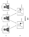
また、フレーム間相関を利用すると、画像信号をさらに圧縮して符号化することが可能となる。例えば図1に示すように、時刻t1乃至t3において、フレーム画像PC1乃至PC3がそれぞれ発生している場合、フレーム画像PC1およびPC2の画像信号の差を演算して、PC12を生成し、また、フレーム画像PC2およびPC3の差を演算して、PC23を生成する。通常、時間的に隣接するフレームの画像は、それ程大きな変化を有していないため、両者の差を演算すると、その差分信号は小さな値のものとなる。そこで、この差分信号を符号化すれば、符号量を圧縮することができる。 Further, when the inter-frame correlation is used, the image signal can be further compressed and encoded. For example, as shown in FIG. 1, when frame images PC1 to PC3 are respectively generated at times t1 to t3, the difference between the image signals of the frame images PC1 and PC2 is calculated to generate PC12. The difference between the images PC2 and PC3 is calculated to generate PC23. Normally, images of frames that are temporally adjacent do not have such a large change. Therefore, when the difference between them is calculated, the difference signal has a small value. Therefore, if this difference signal is encoded, the code amount can be compressed.
しかしながら、差分信号のみを伝送したのでは、元の画像を復元することができない。そこで、各フレームの画像を、Iピクチャ、PピクチャまたはBピクチャの3種類のピクチャタイプのいずれかとし、画像信号を圧縮符号化するようにしている。 However, if only the differential signal is transmitted, the original image cannot be restored. Therefore, the image of each frame is set to one of three types of pictures, ie, I picture, P picture, or B picture, and the image signal is compressed and encoded.
すなわち、例えば図2に示すように、フレームF1乃至F17までの17フレームの画像信号をグループオブピクチャ(GOP)とし、処理の1単位とする。そして、その先頭のフレームF1の画像信号はIピクチャとして符号化し、第2番目のフレームF2はBピクチャとして、また第3番目のフレームF3はPピクチャとして、それぞれ処理する。以下、第4番目以降のフレームF4乃至F17は、BピクチャまたはPピクチャとして交互に処理する。 That is, for example, as shown in FIG. 2, the image signals of 17 frames from frames F1 to F17 are set as a group of pictures (GOP), which is a unit of processing. The image signal of the leading frame F1 is encoded as an I picture, the second frame F2 is processed as a B picture, and the third frame F3 is processed as a P picture. Hereinafter, the fourth and subsequent frames F4 to F17 are alternately processed as a B picture or a P picture.
Iピクチャの画像信号としては、その1フレーム分の画像信号をそのまま伝送する。これに対して、Pピクチャの画像信号としては、基本的には、図2に示すように、それより時間的に先行するIピクチャまたはPピクチャの画像信号からの差分を伝送する。さらにBピクチャの画像信号としては、基本的には、図3に示すように、時間的に先行するフレームまたは後行するフレームの両方の平均値からの差分を求め、その差分を符号化する。 As an image signal of an I picture, the image signal for one frame is transmitted as it is. On the other hand, as the picture signal of the P picture, basically, as shown in FIG. 2, the difference from the picture signal of the I picture or P picture preceding in time is transmitted. Further, as an image signal of a B picture, basically, as shown in FIG. 3, a difference from the average value of both the temporally preceding frame and the succeeding frame is obtained, and the difference is encoded.
図4は、このようにして、動画像信号を符号化する方法の原理を示している。同図に示すように、最初のフレームF1は、Iピクチャとして処理されるため、そのまま伝送データF1Xとして伝送路に伝送される(画像内符号化)。これに対して、第2のフレームF2は、Bピクチャとして処理されるため、時間的に先行するフレームF1と、時間的に後行するフレームF3の平均値との差分が演算され、その差分が伝送データF2Xとして伝送される。 FIG. 4 shows the principle of a method for encoding a moving image signal in this way. As shown in the figure, since the first frame F1 is processed as an I picture, it is transmitted as it is to the transmission path as transmission data F1X (intra-picture coding). In contrast, since the second frame F2 is processed as a B picture, the difference between the temporally preceding frame F1 and the average value of the temporally following frame F3 is calculated, and the difference is calculated as It is transmitted as transmission data F2X.
ただし、このBピクチャとしての処理は、さらに細かく説明すると、4種類存在する。その第1の処理は、元のフレームF2のデータをそのまま伝送データF2Xとして伝送するものであり(SP1)(イントラ符号化)、Iピクチャにおける場合と同様の処理となる。第2の処理は、時間的に後のフレームF3からの差分を演算し、その差分(SP2)を伝送するものである(後方予測符号化)。第3の処理は、時間的に先行するフレームF1との差分(SP3)を伝送するものである(前方予測符号化)。さらに第4の処理は、時間的に先行するフレームF1と後行するフレームF3の平均値との差分(SP4)を生成し、これを伝送データF2Xとして伝送するものである(両方向予測符号化)。 However, there are four types of processing as the B picture in more detail. The first processing is to transmit the data of the original frame F2 as it is as transmission data F2X (SP1) (intra coding), and is the same processing as in the case of an I picture. The second process is to calculate a difference from the temporally subsequent frame F3 and transmit the difference (SP2) (backward predictive coding). The third process is to transmit a difference (SP3) from the temporally preceding frame F1 (forward prediction coding). Further, the fourth process is to generate a difference (SP4) between the average value of the temporally preceding frame F1 and the succeeding frame F3 and transmit this as transmission data F2X (bidirectional predictive coding). .
実際には、上述した4つの方法のうちの伝送データが最も少なくなる方法が採用される。 In practice, the method that minimizes the transmission data among the four methods described above is employed.
なお、差分データを伝送するとき、差分を演算する対象となるフレームの画像(参照画像)との間の動きベクトルx1(フレームF1とF2の間の動きベクトル)(前方予測の場合)、もしくはx2(フレームF3とF2の間の動きベクトル)(後方予測の場合)、またはx1とx2の両方(両方向予測の場合)が、差分データとともに伝送される。 Note that when transmitting difference data, a motion vector x1 (motion vector between frames F1 and F2) between the frame image (reference image) whose difference is to be calculated (in the case of forward prediction), or x2 (Motion vector between frames F3 and F2) (for backward prediction) or both x1 and x2 (for bidirectional prediction) are transmitted along with the difference data.
また、PピクチャのフレームF3は、時間的に先行するフレームF1を参照画像として、このフレームとの差分信号(SP3)と、動きベクトルx3が演算され、これが伝送データF3Xとして伝送される(前方予測符号化)。あるいはまた、元のフレームF3のデータが、そのままデータF3Xとして伝送される(SP1)(イントラ符号化)。これらの方法のうち、Bピクチャにおける場合と同様に、伝送データがより少なくなる方法が選択される。 Also, the frame F3 of the P picture is obtained by calculating a difference signal (SP3) from this frame and the motion vector x3 using the frame F1 temporally preceding as a reference image, and transmitting this as transmission data F3X (forward prediction). Coding). Alternatively, the data of the original frame F3 is transmitted as it is as data F3X (SP1) (intra coding). Among these methods, as in the case of the B picture, a method with less transmission data is selected.
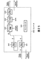
図5は、上述した原理に基づいて、動画像信号を符号化して伝送し、これを復号する装置の構成例を示している。符号化装置1は、入力された映像信号を符号化し、伝送路としての記録媒体3に伝送するようになされている。そして、復号装置2は、記録媒体3に記録された信号を再生し、これを復号して出力するようになされている。
FIG. 5 shows an example of the configuration of an apparatus that encodes and transmits a moving image signal and decodes it based on the principle described above. The
符号化装置1においては、入力された映像信号が前処理回路11に入力され、そこで輝度信号と色信号(本実施の形態の場合、色差信号)が分離され、それぞれA/D変換器12,13でアナログ信号からデジタル信号に変換される。A/D変換器12,13によりデジタル信号に変換された映像信号は、フレームメモリ14に供給され、記憶される。フレームメモリ14は、輝度信号を輝度信号フレームメモリ15に、また、色差信号を色差信号フレームメモリ16に、それぞれ記憶させる。
In the
フォーマット変換回路17は、フレームメモリ14に記憶されたフレームフォーマットの信号を、ブロックフォーマットの信号に変換する。すなわち、図6に示すように、フレームメモリ14に記憶された映像信号は、1ライン当りHドットのラインがVライン集められた、図6(A)に示すようなフレームフォーマットのデータとされている。フォーマット変換回路17は、この1フレームの信号を、図6(B)に示すように、16ラインを単位としてM個のスライスに区分する。そして、各スライスは、M個のマクロブロックに分割される。マクロブロックは、図6(C)に示すように、16×16個の画素(ドット)に対応する輝度信号により構成され、この輝度信号は、さらに8×8ドットを単位とするブロックY[1]乃至Y[4]に区分される。そして、この16×16ドットの輝度信号には、8×8ドットのCb信号と、8×8ドットのCr信号が対応される。
The
このように、ブロックフォーマットに変換されたデータは、フォーマット変換回路17からエンコーダ18に供給され、ここでエンコード(符号化)が行われる。その詳細については、図7を参照して後述する。
In this way, the data converted into the block format is supplied from the
エンコーダ18によりエンコードされた信号は、ビットストリームとして伝送路に出力される。例えば記録回路19に供給され、デジタル信号として記録媒体3に記録される。
復号装置2の再生回路30により記録媒体3より再生されたデータは、デコーダ31に供給され、デコードされる。デコーダ31の詳細については、図12を参照して後述する。
The signal encoded by the
Data reproduced from the
デコーダ31によりデコードされたデータは、フォーマット変換回路32に入力され、ブロックフォーマットからフレームフォーマットに変換される。そして、フレームフォーマットの輝度信号は、フレームメモリ33の輝度信号フレームメモリ34に供給されて記憶され、色差信号は色差信号フレームメモリ35に供給されて記憶される。輝度信号フレームメモリ34と色差信号フレームメモリ35から読み出された輝度信号と色差信号は、それぞれD/A変換器36,37によりアナログ信号に変換され、後処理回路38に供給される。後処理回路38は、輝度信号と色差信号を合成して出力する。
The data decoded by the
次に図7を参照して、エンコーダ18の構成について説明する。符号化される画像データは、マクロブロック単位で動きベクトル検出回路50に入力される。動きベクトル検出回路50は、予め設定されている所定のシーケンスに従って、各フレームの画像データを、Iピクチャ、Pピクチャ、またはBピクチャとして処理する。シーケンシャルに入力される各フレームの画像を、I,P、またはBのいずれのピクチャとして処理するかは、予め定められている(例えば、図2と図3に示したように、フレームF1乃至F17により構成されるグループオブピクチャが、I,B,P,B,P,・・・B,Pとして処理される)。
Next, the configuration of the
Iピクチャとして処理されるフレーム(例えば、フレームF1)の画像データは、動きベクトル検出回路50からフレームメモリ51の前方原画像部51aに転送、記憶され、Bピクチャとして処理されるフレーム(例えば、フレームF2)の画像データは、原画像部51bに転送、記憶され、Pピクチャとして処理されるフレーム(例えば、フレームF3)の画像データは、後方原画像部51cに転送、記憶される。
Image data of a frame processed as an I picture (for example, frame F1) is transferred from the motion
また、次のタイミングにおいて、さらにBピクチャ(フレームF4)またはPピクチャ(フレームF5)として処理すべきフレームの画像が入力されたとき、それまで後方原画像部51cに記憶されていた最初のPピクチャ(フレームF3)の画像データが、前方原画像部51aに転送され、次のBピクチャ(フレームF4)の画像データが、参照原画像部51bに記憶(上書き)され、次のPピクチャ(フレームF5)の画像データが、後方原画像部51cに記憶(上書き)される。このような動作が順次繰り返される。
At the next timing, when an image of a frame to be further processed as a B picture (frame F4) or a P picture (frame F5) is input, the first P picture stored in the rear
フレームメモリ51に記憶された各ピクチャの信号は、そこから読み出され、予測モード切り替え回路52において、フレーム予測モード処理、またはフィールド予測モード処理が行なわれる。
The signal of each picture stored in the
さらにまた、予測判定回路54の制御の下に、演算器53において、画像内予測、前方予測、後方予測、または両方向予測の演算が行なわれる。これらの処理のうち、いずれの処理を行なうかは、予測誤差信号(処理の対象とされている参照画像と、これに対する予測画像との差分)に対応して決定される。このため、動きベクトル検出回路50は、この判定に用いられる予測誤差信号の絶対値和(自乗和でもよい)を生成する。
Furthermore, under the control of the prediction determination circuit 54, the
ここで、予測モード切り替え回路52におけるフレーム予測モードとフィールド予測モードについて説明する。
Here, the frame prediction mode and the field prediction mode in the prediction
フレーム予測モードが設定された場合においては、予測モード切り替え回路52は、動きベクトル検出回路50より供給される4個の輝度ブロックY[1]乃至Y[4]を、そのまま後段の演算器53に出力する。すなわち、この場合においては、図8に示すように、各輝度ブロックに奇数フィールドのラインのデータと、偶数フィールドのラインのデータとが混在した状態となっている。このフレーム予測モードにおいては、4個の輝度ブロック(マクロブロック)を単位として予測が行われ、4個の輝度ブロックに対して1個の動きベクトルが対応される。
When the frame prediction mode is set, the prediction
これに対して、予測モード切り替え回路52は、フィールド予測モードにおいては、図8に示す構成で動きベクトル検出回路50より入力される信号を、図9に示すように、4個の輝度ブロックのうち、輝度ブロックY[1]とY[2]を、例えば奇数フィールドのラインのドットだけで構成させ、他の2個の輝度ブロックY[3]とY[4]を、偶数フィールドのラインのドットだけで構成させて、演算器53に出力する。この場合においては、2個の輝度ブロックY[1]とY[2]に対して、1個の動きベクトルが対応され、他の2個の輝度ブロックY[3]とY[4]に対して、他の1個の動きベクトルが対応される。
On the other hand, in the field prediction mode, the prediction
動きベクトル検出回路50は、フレーム予測モードにおける予測誤差の絶対値和、およびフィールド予測モードにおける予測誤差の絶対値和を予測モード切り替え回路52に出力する。予測モード切り替え回路52は、フレーム予測モードとフィールド予測モードにおける予測誤差の絶対値和を比較し、その値が小さい予測モードに対応する処理を施して、データを演算器53に出力する。
The motion
ただし、このような処理は、実際には動きベクトル検出回路50で行われる。すなわち、動きベクトル検出回路50は、決定されたモードに対応する構成の信号を予測モード切り替え回路52に出力し、予測モード切り替え回路52は、その信号を、そのまま後段の演算器53に出力する。
However, such processing is actually performed by the motion
なお、色差信号は、フレーム予測モードの場合、図8に示すように、奇数フィールドのラインのデータと偶数フィールドのラインのデータとが混在する状態で、演算器53に供給される。また、フィールド予測モードの場合、図9に示すように、各色差ブロックCb,Crの上半分(4ライン)が、輝度ブロックY[1],Y[2]に対応する奇数フィールドの色差信号とされ、下半分(4ライン)が、輝度ブロックY[3],Y[4]に対応する偶数フィールドの色差信号とされる。
In the frame prediction mode, the color difference signal is supplied to the
また、動きベクトル検出回路50は、以下に示すようにして、予測判定回路54において、画像内予測、前方予測、後方予測、または両方向予測のいずれの予測を行なうかを決定するための予測誤差の絶対値和を生成する。
In addition, the motion
すなわち、画像内予測の予測誤差の絶対値和として、参照画像のマクロブロックの信号Aijの総和ΣAijの絶対値|ΣAij|と、マクロブロックの信号Aijの絶対値|Aij|の総和Σ|Aij|の差を求める。また、前方予測の予測誤差の絶対値和として、参照画像のマクロブロックの信号Aijと、予測画像のマクロブロックの信号Bijの差Aij−Bijの絶対値|Aij−Bij|の総和Σ|Aij−Bij|を求める。また、後方予測と両方向予測の予測誤差の絶対値和も、前方予測における場合と同様に(その予測画像を前方予測における場合と異なる予測画像に変更して)求める。 That is, as the sum of absolute values of prediction errors of intra-picture prediction, the absolute value | ΣAij | of the sum ΣAij of the macroblock signal Aij of the reference image and the sum Σ | Aij | of the absolute value | Aij | of the macroblock signal Aij Find the difference. Further, as the absolute value sum of the prediction errors of the forward prediction, the sum Σ | Aij− of the absolute value | Aij−Bij | of the difference Aij−Bij between the macroblock signal Aij of the reference image and the macroblock signal Bij of the predicted image Bij | is obtained. Also, the absolute value sum of the prediction errors of the backward prediction and the bidirectional prediction is obtained in the same manner as in the forward prediction (by changing the prediction image to a prediction image different from that in the forward prediction).
これらの絶対値和は、予測判定回路54に供給される。予測判定回路54は、前方予測、後方予測および両方向予測の予測誤差の絶対値和のうちの最も小さいものを、インタ予測の予測誤差の絶対値和として選択する。さらに、このインタ予測の予測誤差の絶対値和と、画像内予測の予測誤差の絶対値和とを比較し、その小さい方を選択し、この選択した絶対値和に対応するモードを予測モードとして選択する。すなわち、画像内予測の予測誤差の絶対値和の方が小さければ、画像内予測モードが設定される。インタ予測の予測誤差の絶対値和の方が小さければ、前方予測、後方予測または両方向予測モードのうちの対応する絶対値和が最も小さかったモードが設定される。 These sums of absolute values are supplied to the prediction determination circuit 54. The prediction determination circuit 54 selects the smallest one of the absolute value sums of the prediction errors of the forward prediction, the backward prediction, and the bidirectional prediction as the absolute value sum of the prediction errors of the inter prediction. Further, the absolute value sum of the prediction error of the inter prediction and the absolute value sum of the prediction error of the intra prediction are compared, and the smaller one is selected, and the mode corresponding to the selected absolute value sum is set as the prediction mode. select. That is, if the sum of the absolute values of the prediction errors of intra prediction is smaller, the intra prediction mode is set. If the absolute value sum of the prediction errors of inter prediction is smaller, the mode with the smallest corresponding absolute value sum among the forward prediction, backward prediction, and bidirectional prediction modes is set.
このように、動きベクトル検出回路50は、参照画像のマクロブロックの信号を、フレームまたはフィールド予測モードのうち、予測モード切り替え回路52により選択されたモードに対応する構成で、予測モード切り替え回路52を介して演算器53に供給するとともに、4つの予測モードのうちの予測判定回路54により選択された予測モードに対応する予測画像と参照画像の間の動きベクトルを検出し、可変長符号化回路58と動き補償回路64に出力する。上述したように、この動きベクトルとしては、対応する予測誤差の絶対値和が最小となるものが選択される。
As described above, the motion
予測判定回路54は、動きベクトル検出回路50が前方原画像部51aよりIピクチャの画像データを読み出しているとき、予測モードとして、フレームまたはフィールド(画像)内予測モード(動き補償を行わないモード)を設定し、演算器53のスイッチ53dを接点a側に切り替える。これにより、Iピクチャの画像データがDCTモード切り替え回路55に入力される。
When the motion
DCTモード切り替え回路55は、図10または図11に示すように、4個の輝度ブロックのデータを、奇数フィールドのラインと偶数フィールドのラインが混在する状態(フレームDCTモード)、または、分離された状態(フィールドDCTモード)、のいずれかの状態にして、DCT回路56に出力する。
As shown in FIG. 10 or FIG. 11, the DCT
すなわち、DCTモード切り替え回路55は、奇数フィールドと偶数フィールドのデータを混在してDCT処理した場合における符号化効率と、分離した状態においてDCT処理した場合の符号化効率とを比較し、符号化効率の良好なモードを選択する。
That is, the DCT
例えば、入力された信号を、図10に示すように、奇数フィールドと偶数フィールドのラインが混在する構成とし、上下に隣接する奇数フィールドのラインの信号と偶数フィールドのラインの信号の差を演算し、さらにその絶対値の和(または自乗和)を求める。 For example, as shown in FIG. 10, the input signal has a configuration in which odd-numbered field and even-numbered field lines coexist, and calculates the difference between the signal of the odd-numbered line and the even-numbered line adjacent to each other. Further, the sum (or sum of squares) of the absolute values is obtained.
また、入力された信号を、図11に示すように、奇数フィールドと偶数フィールドのラインが分離した構成とし、上下に隣接する奇数フィールドのライン同士の信号の差と、偶数フィールドのライン同士の信号の差を演算し、それぞれの絶対値の和(または自乗和)を求める。 Further, as shown in FIG. 11, the input signal has a configuration in which the odd-numbered field and even-numbered field lines are separated, and the signal difference between the odd-numbered adjacent field lines and the signals of the even-numbered line lines are separated. The sum of absolute values (or the sum of squares) of each is calculated.
さらに、両者(絶対値和)を比較し、小さい値に対応するDCTモードを設定する。すなわち、前者の方が小さければ、フレームDCTモードを設定し、後者の方が小さければ、フィールドDCTモードを設定する。 Furthermore, both (absolute value sum) are compared, and a DCT mode corresponding to a small value is set. That is, if the former is smaller, the frame DCT mode is set, and if the latter is smaller, the field DCT mode is set.
そして、選択したDCTモードに対応する構成のデータをDCT回路56に出力するとともに、選択したDCTモードを示すDCTフラグを、可変長符号化回路58、および動き補償回路64に出力する。
Then, data having a configuration corresponding to the selected DCT mode is output to the
予測モード切り替え回路52における予測モード(図8と図9)と、このDCTモード切り替え回路55におけるDCTモード(図10と図11)を比較して明らかなように、輝度ブロックに関しては、両者の各モードにおけるデータ構造は実質的に同一である。
As is apparent from a comparison between the prediction mode (FIGS. 8 and 9) in the prediction
予測モード切り替え回路52において、フレーム予測モード(奇数ラインと偶数ラインが混在するモード)が選択された場合、DCTモード切り替え回路55においても、フレームDCTモード(奇数ラインと偶数ラインが混在するモード)が選択される可能性が高く、また予測モード切り替え回路52において、フィールド予測モード(奇数フィールドと偶数フィールドのデータが分離されたモード)が選択された場合、DCTモード切り替え回路55において、フィールドDCTモード(奇数フィールドと偶数フィールドのデータが分離されたモード)が選択される可能性が高い。
When the frame prediction mode (mode in which odd lines and even lines are mixed) is selected in the prediction
しかしながら、必ずしも常にこのようにモードが選択されるわけではなく、予測モード切り替え回路52においては、予測誤差の絶対値和が小さくなるようにモードが決定され、DCTモード切り替え回路55においては、符号化効率が良好となるようにモードが決定される。
However, the mode is not always selected in this way, and the prediction
DCTモード切り替え回路55より出力されたIピクチャの画像データは、DCT回路56に入力されてDCT処理され、DCT係数に変換される。このDCT係数は、量子化回路57に入力され、送信バッファ59のデータ蓄積量(バッファ蓄積量)に対応した量子化スケールで量子化された後、可変長符号化回路58に入力される。
The I-picture image data output from the DCT
可変長符号化回路58は、量子化回路57より供給される量子化スケール(スケール)に対応して、量子化回路57より供給される画像データ(いまの場合、Iピクチャのデータ)を、例えばハフマン符号などの可変長符号に変換し、送信バッファ59に出力する。
The variable
可変長符号化回路58にはまた、量子化回路57より量子化スケール(スケール)、予測判定回路54より予測モード(画像内予測、前方予測、後方予測、または両方向予測のいずれが設定されたかを示すモード)、動きベクトル検出回路50より動きベクトル、予測モード切り替え回路52より予測フラグ(フレーム予測モードまたはフィールド予測モードのいずれが設定されたかを示すフラグ)、およびDCTモード切り替え回路55が出力するDCTフラグ(フレームDCTモードまたはフィールドDCTモードのいずれが設定されたかを示すフラグ)が入力されており、これらも可変長符号化される。
The variable
送信バッファ59は、入力されたデータを一時蓄積し、蓄積量に対応するデータを量子化回路57に出力する。送信バッファ59は、そのデータ残量が許容上限値まで増量すると、量子化制御信号によって量子化回路57の量子化スケールを大きくすることにより、量子化データのデータ量を低下させる。また、これとは逆に、データ残量が許容下限値まで減少すると、送信バッファ59は、量子化制御信号によって量子化回路57の量子化スケールを小さくすることにより、量子化データのデータ量を増大させる。このようにして、送信バッファ59のオーバフローまたはアンダフローが防止される。
The
そして、送信バッファ59に蓄積されたデータは、所定のタイミングで読み出され、伝送路に出力され、例えば記録回路19を介して記録媒体3に記録される。
The data stored in the
一方、量子化回路57より出力されたIピクチャのデータは、逆量子化回路60に入力され、量子化回路57より供給される量子化スケールに対応して逆量子化される。逆量子化回路60の出力は、IDCT(逆離散コサイン変換)回路61に入力され、逆離散コサイン変換処理された後、演算器62を介してフレームメモリ63の前方予測画像部63a供給されて記憶される。
On the other hand, the I picture data output from the
動きベクトル検出回路50は、シーケンシャルに入力される各フレームの画像データを、たとえば、I,B,P,B,P,B・・・のピクチャとしてそれぞれ処理する場合、最初に入力されたフレームの画像データをIピクチャとして処理した後、次に入力されたフレームの画像をBピクチャとして処理する前に、さらにその次に入力されたフレームの画像データをPピクチャとして処理する。Bピクチャは、後方予測を伴うため、後方予測画像としてのPピクチャが先に用意されていないと、復号することができないからである。
The motion
そこで動きベクトル検出回路50は、Iピクチャの処理の次に、後方原画像部51cに記憶されているPピクチャの画像データの処理を開始する。そして、上述した場合と同様に、マクロブロック単位でのフレーム間差分(予測誤差)の絶対値和が、動きベクトル検出回路50から予測モード切り替え回路52と予測判定回路54に供給される。予測モード切り替え回路52と予測判定回路54は、このPピクチャのマクロブロックの予測誤差の絶対値和に対応して、フレーム/フィールド予測モード、または画像内予測、前方予測、後方予測、もしくは両方向予測の予測モードを設定する。
Therefore, the motion
演算器53は、画像内予測モードが設定されたとき、スイッチ53dを上述したように接点a側に切り替える。したがって、このデータは、Iピクチャのデータと同様に、DCTモード切り替え回路55、DCT回路56、量子化回路57、可変長符号化回路58、および送信バッファ59を介して伝送路に伝送される。また、このデータは、逆量子化回路60、IDCT回路61、および演算器62を介してフレームメモリ63の後方予測画像部63bに供給されて記憶される。
When the in-picture prediction mode is set, the
また、前方予測モードが設定された場合、スイッチ53dが接点bに切り替えられるとともに、フレームメモリ63の前方予測画像部63aに記憶されている画像(いまの場合、Iピクチャの画像)データが読み出され、動き補償回路64により、動きベクトル検出回路50が出力する動きベクトルに対応して動き補償される。すなわち、動き補償回路64は、予測判定回路54より前方予測モードの設定が指令されたとき、前方予測画像部63aの読み出しアドレスを、動きベクトル検出回路50が、現在、出力しているマクロブロックの位置に対応する位置から動きベクトルに対応する分だけずらしてデータを読み出し、予測画像データを生成する。
When the forward prediction mode is set, the
動き補償回路64より出力された予測画像データは、演算器53aに供給される。演算器53aは、予測モード切り替え回路52より供給された参照画像のマクロブロックのデータから、動き補償回路65より供給された、このマクロブロックに対応する予測画像データを減算し、その差分(予測誤差)を出力する。この差分データは、DCTモード切り替え回路55、DCT回路56、量子化回路57、可変長符号化回路58、および送信バッファ59を介して伝送路に伝送される。また、この差分データは、逆量子化回路60、およびIDCT回路61により局所的に復号され、演算器62に入力される。
The predicted image data output from the
この演算器62にはまた、演算器53aに供給されている予測画像データと同一のデータが供給されている。演算器62は、IDCT回路61が出力する差分データに、動き補償回路64が出力する予測画像データを加算する。これにより、元の(復号した)Pピクチャの画像データが得られる。このPピクチャの画像データは、フレームメモリ63の後方予測画像部63bに供給されて記憶される。
The
動きベクトル検出回路50は、このように、IピクチャとPピクチャのデータが前方予測画像部63aと後方予測画像部63bにそれぞれ記憶された後、次にBピクチャの処理を実行する。予測モード切り替え回路52と予測判定回路54は、マクロブロック単位でのフレーム間差分の絶対値和の大きさに対応して、フレーム/フィールドモードを設定し、また、予測モードを画像内予測モード、前方予測モード、後方予測モード、または両方向予測モードのいずれかに設定する。
As described above, the motion
上述したように、画像内予測モードまたは前方予測モードの時、スイッチ53dは接点aまたはbに切り替えられる。このとき、Pピクチャにおける場合と同様の処理が行われ、データが伝送される。
As described above, in the intra prediction mode or the forward prediction mode, the
これに対して、後方予測モードまたは両方向予測モードが設定された時、スイッチ53dは、接点cまたはdにそれぞれ切り替えられる。
On the other hand, when the backward prediction mode or the bidirectional prediction mode is set, the
スイッチ53dが接点cに切り替えられている後方予測モードの時、後方予測画像部63bに記憶されている画像(いまの場合、Pピクチャの画像)データが読み出され、動き補償回路64により、動きベクトル検出回路50が出力する動きベクトルに対応して動き補償される。すなわち、動き補償回路64は、予測判定回路54より後方予測モードの設定が指令されたとき、後方予測画像部63bの読み出しアドレスを、動きベクトル検出回路50が、現在、出力しているマクロブロックの位置に対応する位置から動きベクトルに対応する分だけずらしてデータを読み出し、予測画像データを生成する。
In the backward prediction mode in which the
動き補償回路64より出力された予測画像データは、演算器53bに供給される。演算器53bは、予測モード切り替え回路52より供給された参照画像のマクロブロックのデータから、動き補償回路64より供給された予測画像データを減算し、その差分を出力する。この差分データは、DCTモード切り替え回路55、DCT回路56、量子化回路57、可変長符号化回路58、および送信バッファ59を介して伝送路に伝送される。
The predicted image data output from the
スイッチ53dが接点dに切り替えられている両方向予測モードの時、前方予測画像部63aに記憶されている画像(いまの場合、Iピクチャの画像)データと、後方予測画像部63bに記憶されている画像(いまの場合、Pピクチャの画像)データが読み出され、動き補償回路64により、動きベクトル検出回路50が出力する動きベクトルに対応して動き補償される。
In the bidirectional prediction mode in which the
すなわち、動き補償回路64は、予測判定回路54より両方向予測モードの設定が指令されたとき、前方予測画像部63aと後方予測画像部63bの読み出しアドレスを、動きベクトル検出回路50がいま出力しているマクロブロックの位置に対応する位置から動きベクトル(この場合の動きベクトルは、前方予測画像用と後方予測画像用の2つとなる)に対応する分だけずらしてデータを読み出し、予測画像データを生成する。
That is, in the
動き補償回路64より出力された予測画像データは、演算器53cに供給される。演算器53cは、動きベクトル検出回路50より供給された参照画像のマクロブロックのデータから、動き補償回路64より供給された予測画像データの平均値を減算し、その差分を出力する。この差分データは、DCTモード切り替え回路55、DCT回路56、量子化回路57、可変長符号化回路58、および送信バッファ59を介して伝送路に伝送される。
The predicted image data output from the
Bピクチャの画像は、他の画像の予測画像とされることがないため、フレームメモリ63には記憶されない。
The B picture image is not stored in the
なお、フレームメモリ63において、前方予測画像部63aと後方予測画像部63bは、必要に応じてバンク切り替えが行われ、所定の参照画像に対して、一方または他方に記憶されているものを、前方予測画像あるいは後方予測画像として切り替えて出力することができる。
Note that, in the
上述した説明においては、輝度ブロックを中心として説明をしたが、色差ブロックについても同様に、図8乃至図11に示すマクロブロックを単位として処理されて伝送される。なお、色差ブロックを処理する場合の動きベクトルは、対応する輝度ブロックの動きベクトルを垂直方向と水平方向に、それぞれ1/2にしたものが用いられる。 In the above description, the luminance block is mainly described, but the color difference block is also processed and transmitted in units of macroblocks shown in FIGS. Note that the motion vector when processing the color difference block is obtained by halving the motion vector of the corresponding luminance block in the vertical direction and the horizontal direction, respectively.
図12は、図5のデコーダ31の構成を示すブロック図である。伝送路(記録媒体3)を介して伝送された符号化された画像データは、図示せぬ受信回路で受信されたり、再生装置で再生され、受信バッファ81に一時記憶された後、復号回路90の可変長復号回路82に供給される。可変長復号回路82は、受信バッファ81より供給されたデータを可変長復号し、動きベクトル、予測モード、予測フラグ、およびDCTフラグを動き補償回路87に出力し、量子化スケールを逆量子化回路83に出力するとともに、復号された画像データを逆量子化回路83に出力する。
FIG. 12 is a block diagram showing a configuration of the
逆量子化回路83は、可変長復号回路82より供給された画像データを、同じく可変長復号回路82より供給された量子化スケールに従って逆量子化し、IDCT回路84に出力する。逆量子化回路83より出力されたデータ(DCT係数)は、IDCT回路84により、逆離散コサイン変換処理が施され、演算器85に供給される。
The
IDCT回路84より演算器85に供給された画像データが、Iピクチャのデータである場合、そのデータは演算器85より出力され、演算器85に後に入力される画像データ(PまたはBピクチャのデータ)の予測画像データ生成のために、フレームメモリ86の前方予測画像部86aに供給されて記憶される。また、このデータは、フォーマット変換回路32(図5)に出力される。
When the image data supplied from the
IDCT回路84より供給された画像データが、その1フレーム前の画像データを予測画像データとするPピクチャのデータであり、前方予測モードのデータである場合、フレームメモリ86の前方予測画像部86aに記憶されている、1フレーム前の画像データ(Iピクチャのデータ)が読み出され、動き補償回路87で可変長復号回路82より出力された動きベクトルに対応する動き補償が施される。そして、演算器85において、IDCT回路84より供給された画像データ(差分のデータ)と加算され、出力される。この加算されたデータ、すなわち、復号されたPピクチャのデータは、演算器85に後に入力される画像データ(BピクチャまたはPピクチャのデータ)の予測画像データ生成のために、フレームメモリ86の後方予測画像部86bに供給されて記憶される。
When the image data supplied from the
Pピクチャのデータであっても、画像内予測モードのデータは、Iピクチャのデータと同様に、演算器85において処理は行われず、そのまま後方予測画像部86bに記憶される。
Even in the case of P picture data, the intra prediction mode data is not processed by the
このPピクチャは、次のBピクチャの次に表示されるべき画像であるため、この時点では、まだフォーマット変換回路32へ出力されない(上述したように、Bピクチャの後に入力されたPピクチャが、Bピクチャより先に処理され、伝送されている)。 Since this P picture is an image to be displayed next to the next B picture, at this point of time, it is not yet output to the format conversion circuit 32 (as described above, the P picture input after the B picture is Processed and transmitted before B picture).
IDCT回路84より供給された画像データが、Bピクチャのデータである場合、可変長復号回路82より供給された予測モードに対応して、フレームメモリ86の前方予測画像部86aに記憶されているIピクチャの画像データ(前方予測モードの場合)、後方予測画像部86bに記憶されているPピクチャの画像データ(後方予測モードの場合)、または、その両方の画像データ(両方向予測モードの場合)が読み出され、動き補償回路87において、可変長復号回路82より出力された動きベクトルに対応する動き補償が施されて、予測画像が生成される。但し、動き補償を必要としない場合(画像内予測モードの場合)、予測画像は生成されない。
When the image data supplied from the
このようにして、動き補償回路87で動き補償が施されたデータは、演算器85において、IDCT回路84の出力と加算される。この加算出力は、フォーマット変換回路32に出力される。
In this way, the data subjected to motion compensation by the
ただし、この加算出力はBピクチャのデータであり、他の画像の予測画像生成のために利用されることがないため、フレームメモリ86には記憶されない。
However, since this addition output is B picture data and is not used for generating a predicted image of another image, it is not stored in the
Bピクチャの画像が出力された後、後方予測画像部86bに記憶されているPピクチャの画像データが読み出され、動き補償回路87を介して演算器85に供給される。但し、このとき、動き補償は行われない。
After the B picture image is output, the P picture image data stored in the backward predicted
なお、このデコーダ31には、図5のエンコーダ18における予測モード切り替え回路52とDCTモード切り替え回路55に対応する回路が図示されていないが、これらの回路に対応する処理、すなわち、奇数フィールドと偶数フィールドのラインの信号が分離された構成を元の構成に必要に応じて戻す処理は、動き補償回路87により実行される。
The
また、上述した説明においては、輝度信号の処理について説明したが、色差信号の処理も同様に行われる。ただし、この場合の動きベクトルは、輝度信号用の動きベクトルを、垂直方向および水平方向に1/2にしたものが用いられる。 In the above description, the luminance signal processing has been described, but the color difference signal processing is performed in the same manner. However, the motion vector in this case is obtained by halving the luminance signal motion vector in the vertical and horizontal directions.
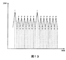
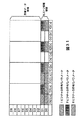
図13は、符号化された画像の品質を示している。画像の品質(SNR:Signal to Noise Ratio)は、ピクチャタイプに対応して制御され、Iピクチャ、およびPピクチャは高品質とされ、Bピクチャは、I,Pピクチャに比べて劣る品質とされて伝送される。これは、人間の視覚特性を利用した手法であり、全ての画像品質を平均化するよりも、品質を振動させたほうが視覚上の画質が良くなるためである。このピクチャタイプに対応した画質の制御は、図7の量子化回路57により実行される。
FIG. 13 shows the quality of the encoded image. Image quality (SNR: Signal to Noise Ratio) is controlled according to the picture type, I picture and P picture are of high quality, and B picture is inferior to I and P pictures. Is transmitted. This is a technique using human visual characteristics, and the visual image quality is better when the quality is oscillated than when all the image qualities are averaged. The image quality control corresponding to this picture type is executed by the
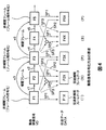
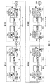
図14及び図15は、本発明を適用したトランスコーダ101の構成を示しており、図15は、図14のさらに詳細な構成を示している。このトランスコーダ101は、復号装置102に入力された符号化ビデオビットストリーム(encoded video bit stream)のGOP構造及びビットレートを、オペレータの所望するGOP構造及びビットレートに変換する。このトランスコーダ101の機能を説明するために、図15には図示されていないが、このトランスコーダ101の前段に、このトランスコーダ101とほぼ同様の機能を有した3つのトランスコーダが接続されているものとする。つまり、ビットストリームのGOP構造及びビットレートをさまざまに変更するために、第1のトランスコーダ、第2のトランスコーダ、および第3のトランスコーダが順に直列に接続され、その第3のトランスコーダの後ろに、この図15に示された第4のトランスコーダが接続されているものとする。
14 and 15 show the configuration of the transcoder 101 to which the present invention is applied, and FIG. 15 shows the more detailed configuration of FIG. The transcoder 101 converts the GOP structure and bit rate of the encoded video bit stream input to the
本発明の以下の説明において、この第1のトランスコーダにおいて行われた符号化処理を第1世代の符号化処理と定義し、第1のトランスコーダの後ろに接続された第2のトランスコーダにおいて行われた符号化処理を第2世代の符号化処理と定義し、第2のトランスコーダの後ろに接続された第3のトランスコーダにおいて行われた符号化処理を第3世代の符号化処理と定義し、第3のトランスコーダの後ろに接続された第4のトランスコーダ(図15に示されたトランスコーダ101)において行われる符号化処理を第4世代の符号化処理または現在の符号化処理と定義することにする。 In the following description of the present invention, the encoding process performed in the first transcoder is defined as the first generation encoding process, and the second transcoder connected after the first transcoder. The encoding process performed is defined as the second generation encoding process, and the encoding process performed in the third transcoder connected after the second transcoder is defined as the third generation encoding process. The encoding process performed in the fourth transcoder (transcoder 101 shown in FIG. 15) defined and connected after the third transcoder is the fourth generation encoding process or the current encoding process. We will define
また、第1世代の符号化処理において生成された符号化パラメータを第1世代の符号化パラメータと呼び、第2世代の符号化処理において生成された符号化パラメータを第2世代の符号化パラメータと呼び、第3世代の符号化処理において生成された符号化パラメータを第3世代の符号化パラメータと呼び、第4世代の符号化処理において生成された符号化パラメータを第4世代の符号化パラメータまたは現在の符号化パラメータと呼ぶことにする。 In addition, the encoding parameter generated in the first generation encoding process is referred to as a first generation encoding parameter, and the encoding parameter generated in the second generation encoding process is referred to as a second generation encoding parameter. The encoding parameter generated in the third generation encoding process is referred to as the third generation encoding parameter, and the encoding parameter generated in the fourth generation encoding process is referred to as the fourth generation encoding parameter or This is called the current encoding parameter.
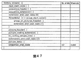
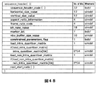
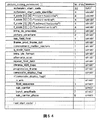
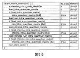
まず、この図15に示されたトランスコーダ101に供給される符号化ビデオストリームST(3rd)について説明する。ST(3rd)は、このトランスコーダ101の前段に設けられている第3のトランスコーダにおける第3世代の符号化処理において生成された第3世代の符号化ストリームであることを表わしている。この第3世代の符号化処理において生成された符号化ビデオストリームST(3rd)には、第3の符号化処理において生成された第3世代の符号化パラメータが、この符号化ビデオストリームST(3rd)のシーケンス層、GOP層、ピクチャ層、スライス層、及びマクロブロック層に、sequence_header() 関数、sequence_extension() 関数、group_of_pictures_header()関数、picture_header()関数,picture_coding_extension()関数、picture_data()関数、slice() 関数、及びmacroblock()関数として記述されている。このように第3の符号化処理によって生成された第3の符号化ストリームに、第3の符号化処理において使用した第3の符号化パラメータを記述することはMPEG2規格において定義されていることであって、何ら新規性は無い。 First, the encoded video stream ST (3rd) supplied to the transcoder 101 shown in FIG. 15 will be described. ST (3rd) represents a third generation encoded stream generated in the third generation encoding process in the third transcoder provided in the preceding stage of the transcoder 101. In the encoded video stream ST (3rd) generated in the third generation encoding process, the third generation encoding parameter generated in the third encoding process includes the encoded video stream ST (3rd ) Sequence layer, GOP layer, picture layer, slice layer, and macroblock layer, sequence_header () function, sequence_extension () function, group_of_pictures_header () function, picture_header () function, picture_coding_extension () function, picture_data () function, It is described as slice () function and macroblock () function. The description of the third encoding parameter used in the third encoding process in the third encoded stream generated by the third encoding process is defined in the MPEG2 standard. There is no novelty.
本発明のトランスコーダ101におけるユニークな点は、この第3の符号化ストリームST(3rd)中に、第3の符号化パラメータを記述するでけでなく、第1世代及び第2世代の符号化処理において生成された第1世代及び第2世代の符号化パラメータも記述されているという点である。 The unique point in the transcoder 101 of the present invention is that not only the third encoding parameter is described in the third encoded stream ST (3rd) but also the first generation and second generation encodings. The first generation and second generation encoding parameters generated in the process are also described.
具体的には、この第1世代及び第2世代の符号化パラメータは、第3世代の符号化ビデオストリームST(3rd)のピクチャ層のユーザデータエリアに、ヒストリストリームhistory_stream()として記述されている。本発明においては、第3世代の符号化ビデオストリームST(3rd)のピクチャ層のユーザデータエリアに記述されているヒストリストリームを、「ヒストリ情報」、または「履歴情報」と呼び、このヒストリストリームとして記述されている符号化パラメータを「ヒストリパラメータ」、または「履歴パラメータ」と呼んでいる。 Specifically, the first generation and second generation encoding parameters are described as a history stream history_stream () in the user data area of the picture layer of the third generation encoded video stream ST (3rd). . In the present invention, the history stream described in the user data area of the picture layer of the third generation encoded video stream ST (3rd) is called “history information” or “history information”. The described encoding parameters are called “history parameters” or “history parameters”.
また別の呼び方として、第3世代の符号化ストリームST(3rd)に記述されている第3世代の符号化パラメータを「現在の符号化パラメータ」と呼んだ場合には、第3世代の符号化処理からみて第1世代及び第2世代の符号化処理は、過去に行なわれた符号化処理であるので、第3世代の符号化ストリームST(3rd)のピクチャ層のユーザデータエリアに記述されているヒストリストリームとして記述されている符号化パラメータを「過去の符号化パラメータ」とも呼んでいる。 Alternatively, if the third generation encoding parameter described in the third generation encoded stream ST (3rd) is called “current encoding parameter”, the third generation code In view of the encoding process, the first generation and second generation encoding processes are encoding processes performed in the past, and are therefore described in the user data area of the picture layer of the third generation encoded stream ST (3rd). The encoding parameter described as a history stream is also called “past encoding parameter”.
このように、この第3の符号化ストリームST(3rd)中に、第3の符号化パラメータを記述するでけでなく、第1世代及び第2世代の符号化処理において生成された第1世代及び第2世代の符号化パラメータを記述する理由は、トランスコーディング処理によって符号化ストリームのGOP構造やビットレートの変更を繰り返したとしても、画質劣化を防止することができるからである。 Thus, not only the third encoding parameter is described in the third encoded stream ST (3rd) but also the first generation generated in the first generation and second generation encoding processes. The reason why the second generation encoding parameters are described is that even if the GOP structure and bit rate of the encoded stream are repeatedly changed by the transcoding process, the image quality can be prevented from being deteriorated.
例えば、あるピクチャを第1世代の符号化処理においてPピクチャとして符号化し、第1世代の符号化ストリームのGOP構造を変更するために、第2世代の符号化処理においてそのピクチャをBピクチャとして符号化し、第2世代の符号化ストリームのGOP構造をさらに変更するために、第3世代の符号化処理において、再度そのピクチャをPピクチャとして符号化することが考えられる。MPEG規格に基づく符号化処理及び復号処理は100%可逆の処理ではないので、符号化及び復号処理を繰り返す毎に画質が劣化していくことは知られている。 For example, a picture is encoded as a P picture in the first generation encoding process, and the picture is encoded as a B picture in the second generation encoding process in order to change the GOP structure of the first generation encoded stream. In order to further change the GOP structure of the second generation encoded stream, it may be possible to encode the picture again as a P picture in the third generation encoding process. Since encoding processing and decoding processing based on the MPEG standard are not 100% reversible processing, it is known that image quality deteriorates every time encoding and decoding processing is repeated.
このような場合に、第3の世代の符号化処理において、量子化スケール、動きベクトル、予測モードなどの符号化パラメータをもう一度計算するのではなくて、第1世代の符号化処理において生成された量子化スケール、動きベクトル、予測モードなどの符号化パラメータを再利用する。第3世代の符号化処理によって新しく生成された量子化スケール、動きベクトル、予測モードなどの符号化パラメータよりも、第1世代の符号化処理によって新しく生成された量子化スケール、動きベクトル、予測モードなどの符号化パラメータの方が、明らかに精度が良いので、この第1世代のパラメータを再利用することによって、符号化及び復号処理を繰り返したとしても画質劣化を少なくすることができる。 In such a case, in the third generation encoding process, the encoding parameters such as the quantization scale, the motion vector, and the prediction mode are not calculated again, but generated in the first generation encoding process. Reuse coding parameters such as quantization scale, motion vector, and prediction mode. Compared to encoding parameters such as quantization scale, motion vector, and prediction mode newly generated by the third generation encoding process, quantization scale, motion vector, and prediction mode newly generated by the first generation encoding process. Since the encoding parameters such as are clearly more accurate, the image quality degradation can be reduced by reusing the first generation parameters even if the encoding and decoding processes are repeated.
上述した本発明にかかる処理を説明するために、図15に示された第4世代のトランスコーダ101の処理を例に挙げてより詳しく説明する。 In order to describe the processing according to the present invention described above, the processing of the fourth generation transcoder 101 shown in FIG. 15 will be described in more detail as an example.
復号装置102は、第3世代の符号化ビットストリームST(3rd)に含まれている符号化ビデオを第3世代の符号化パラメータを使用して復号し、復号されたベースバンドのデジタルビデオデータを生成するための装置である。さらに、復号装置102は、第3世代の符号化ビットストリームST(3rd)のピクチャ層のユーザデータエリアにヒストリストリームとして記述されている第1世代及び第2世代の符号化パラメータをデコードするための装置でもある。
The
具体的には、図16に示されているように、復号装置102は、図5の復号装置2のデコーダ31(図12)と基本的に同様の構成とされ、供給されたビットストリームをバッファリングするための受信バッファ81、符号化ビットストリームを可変長復号するための可変長復号回路112、可変長復号されたデータを可変長復号回路112から供給された量子化スケールに従って逆量子化する逆量子化回路83、逆量子化されたDCT係数を逆離散コサイン変換するIDCT回路84、及び動き補償処理を行うための演算器85、フレームメモリ86及び動き補償回路87を備えている。
Specifically, as shown in FIG. 16, the
可変長復号回路112は、第3世代の符号化ビットストリームST(3rd)を復号処理するために、この第3世代の符号化ビットストリームST(3rd)のピクチャ層、スライス層及びマクロブロック層に記述されている第3世代の符号化パラメータを抽出する。たとえば、この可変長復号回路112において抽出される第3世代の符号化パラメータは、ピクチャタイプを示すpicture_coding_type、量子化スケールステップサイズを示すquantiser_scale_code、予測モードを示すmacroblock_type、動きベクトルを示すmotion_vector、Frame予測モードかField予測モードかを示すframe/field_motion_type、及びFrameDCTモードかField DCTモードかを示すdct_type等である。この可変長復号回路112において抽出されたquatntiser_scale_codeは、逆量子化回路83に供給され、picture_coding_type、quatntiser_scale_code、macroblock_type、motion_vector、frame/field_motion_type、dct_type等のパラメータは、動き補償回路87に供給される。
The variable
可変長復号回路112は、第3世代の符号化ビットストリームST(3rd)を復号処理するために必要なこれらの符号化パラメータだけではなく、後段の第5世代のトランスコーダに第3世代のヒストリ情報として伝送されるべき符号化パラメータを、第3世代の符号化ビットストリームST(3rd)のシーケンス層、GOP層、ピクチャ層、スライス層、及びマクロブロック層から抽出する。もちろん、第3世代の復号処理に使用されたpicture_coding_type、quatntiser_scale_code、macroblock_type、motion_vector、frame/field_motion_type、dct_type等の第3世代の符号化パラメータは、この第3世代のヒストリ情報に含まれている。ヒストリ情報としてどのような符号化パラメータを抽出するかについては、伝送容量などに応じてオペレータやホストコンピュータ側からあらかじめ設定されている。
The variable
さらに、可変長復号回路112は、第3世代の符号化ビットストリームST(3rd)のピクチャ層のユーザデータエリアに記述されているユーザデータを抽出し、そのユーザデータをヒストリデコーディング装置104に供給する。
Further, the variable
このヒストリデコーディング装置104は、第3世代の符号化ビットストリームST(3rd)のピクチャ層に記述されていたユーザデータから、ヒストリ情報として記述されている第1世代の符号化パラメータ及び第2世代の符号化パラメータ(直前の世代よりさらに前の世代の符号化パラメータ)を抽出するための回路である。具体的には、ヒストリデコーディング装置104は、受け取ったユーザデータのシンタックスを解析することによって、ユーザデータの中に記述されている固有のHistory_Data_Idを検出し、これによって、converted_history_stream()を抽出することができる。さらに、ヒストリデコーディング装置104は、converted_history_stream()中にある所定間隔に挿入されている1ビットのマーカービット(marker_bit)を取りさることによって、history_stream()を得、そして、そのhistory_stream()のシンタックスを解析することによって、history_stream()中に記述されている第1世代及び第2世代の符号化パラメータを得ることができる。このヒストリデコーディング装置104の詳しい動作については、後述する。
The
ヒストリ情報多重化装置103は、第1世代、第2世代及び第3世代の符号化パラメータを、第4世代の符号化処理を行う符号化装置106に供給するために、復号装置102においてデコードされたベースバンドのビデオデータに、これらの第1世代、第2世代及び第3世代の符号化パラメータを多重化するための回路である。具体的には、ヒストリ情報多重化装置103は、復号装置102の演算器85から出力されたベースバンドのビデオデータ、復号装置102の可変長復号装置112から出力された第3世代の符号化パラメータ、並びに、ヒストリデコーディング装置104から出力された第1世代の符号化パラメータと第2世代の符号化パラメータとを受け取り、このベースバンドのビデオデータに、これらの第1世代、第2世代及び第3世代の符号化パラメータを多重化する。第1世代、第2世代及び第3世代の符号化パラメータが多重化されたベースバンドのビデオデータは、伝送ケーブルを介してヒストリ情報分離装置105に供給される。
The history
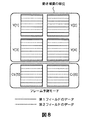
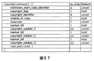
次に、これらの第1世代、第2世代及び第3世代の符号化パラメータのベースバンドビデオデータへの多重化の方法について、図17及び図18を参照して説明する。図17は、MPEG規格において定義されている、16ピクセル×16ピクセルからなる1つのマクロブロックを示している。この16ピクセル×16ピクセルのマクロブロックは、輝度信号に関しては4つの8ピクセル×8ピクセルからなるサブブロック(Y[0],[1],[2]及びY[3])と、色差信号に関しては4つの8ピクセル×8ピクセルからなるサブブロック(Cr[0],r[1],b[0],及びCb[1])から構成されている。 図18は、ビデオデータのあるフォーマットを表している。このフォーマットは、ITU勧告-RDT601において定義されているフォーマットであって、放送業界において使用されている所謂「D1フォーマット」をあらわしている。このD1フォーマットは、10ビットのビデオデータを伝送するためのフォーマットとして規格化されたので、ビデオデータの1ピクセルを10ビットで表現できるようになっている。 Next, a method of multiplexing the first generation, second generation, and third generation encoding parameters into the baseband video data will be described with reference to FIGS. FIG. 17 shows one macro block of 16 pixels × 16 pixels defined in the MPEG standard. This macro block of 16 pixels × 16 pixels has four sub-blocks (Y [0], [1], [2] and Y [3]) consisting of four 8 pixels × 8 pixels with respect to the luminance signal, and a color difference signal. Consists of four sub-blocks (Cr [0], r [1], b [0], and Cb [1]) each consisting of 8 pixels × 8 pixels. FIG. 18 shows a format of video data. This format is a format defined in the ITU recommendation-RDT 601 and represents a so-called “D1 format” used in the broadcasting industry. Since this D1 format has been standardized as a format for transmitting 10-bit video data, one pixel of the video data can be expressed by 10 bits.
MPEG規格によってデコードされたベースバンドのビデオデータは8ビットであるので、本発明のトランスコーダにおいては、図18に示したように、D1フォーマットの10ビットのうち上位8ビット(D9乃至D2)を使用して、MPEG規格にもとづいてデコードされたベースバンドのビデオデータを伝送するようにしている。このように、復号された8ビットのビデオデータをD1フォーマットに書き込むと、下位2ビット(D1とD0)は、空きビット(unallocated bits)となる。本発明のトランスコーダではこの空きエリア(unallocated area)を利用して、ヒストリ情報を伝送するようにしている。 Since the baseband video data decoded according to the MPEG standard is 8 bits, in the transcoder of the present invention, as shown in FIG. 18, the upper 8 bits (D9 to D2) out of 10 bits of the D1 format are used. It is used to transmit baseband video data decoded based on the MPEG standard. As described above, when the decoded 8-bit video data is written in the D1 format, the lower 2 bits (D1 and D0) become unallocated bits. In the transcoder of the present invention, history information is transmitted using this unallocated area.
この図18に記載されたデータブロックは、各サブブロック(Y[0],Y[1],Y[2],Y[3],Cr[0],Cr[1],Cb[0],Cb[1])における1ピクセルを伝送するためのデータブロックであるので、1マクロブロックのデータを伝送するためには、この図18に示されているデータブロックが64個伝送される。下位2ビット(D1とD0)を使用すれば、1マクロブロックのビデオデータに対して、合計で1024(=16×64)ビットのヒストリ情報を伝送できる。従って、1世代分のヒストリ情報は、256ビットとなるように生成されているので、過去の4(=1024/256)世代分のヒストリ情報を1マクロブロックのビデオデータに対して重畳することができる。図18に示した例では、第1世代のヒストリ情報、第2世代のヒストリ情報、並びに、第3世代のヒストリ情報が重畳されている。 The data block shown in FIG. 18 includes sub-blocks (Y [0], Y [1], Y [2], Y [3], Cr [0], Cr [1], Cb [0], Since this is a data block for transmitting one pixel in Cb [1]), 64 data blocks shown in FIG. 18 are transmitted to transmit one macroblock data. If the lower 2 bits (D1 and D0) are used, a total of 1024 (= 16 × 64) bits of history information can be transmitted for one macroblock of video data. Accordingly, since history information for one generation is generated to be 256 bits, history information for the past 4 (= 1024/256) generations may be superimposed on video data of one macroblock. it can. In the example shown in FIG. 18, the first generation history information, the second generation history information, and the third generation history information are superimposed.
ヒストリ情報分離装置105は、D1フォーマットとして伝送されたデータの上位8ビットから、ベースバンドビデオデータを抽出し、下位2ビットからヒストリ情報を抽出するための回路である。図15に示した例では、ヒストリ情報分離装置105は、伝送データからベースバンドのビデオデータを抽出して、そのビデオデータを符号化装置106に供給するとともに、伝送データから第1世代、第2世代及び第3世代のヒストリ情報を抽出して、符号化装置106とヒストリエンコーディング装置107にそれぞれ供給する。
The history
符号化装置106は、ヒストリ情報分離装置105から供給されたベースバンドのビデオデータを、オペレータまたはホストコンピュータから指定されたGOP構造及びビットレートを有するビットストリームになるように符号化するための装置である。なお、GOP構造を変更するとは、たとえば、GOPに含まれるピクチャの数、IピクチャとIピクチャの間に存在するPピクチャの数、及びIピクチャとPピクチャ(またはIピクチャ)の間に存在するBピクチャの数を変更することを意味する。
The
図15に示された例では、供給されたベースバンドのビデオデータには、第1世代、第2世代及び第3世代のヒストリ情報が重畳されているので、この符号化装置106は、再符号化処理による画質劣化が少なくなるように、これらのヒストリ情報を選択的に再利用して第4世代の符号化処理を行う。
In the example shown in FIG. 15, since the history information of the first generation, the second generation, and the third generation is superimposed on the supplied baseband video data, the
図19は、この符号化装置106に設けられている符号化装置106の具体的な構成を示している図である。この符号化装置106は、基本的には、図7に示したエンコーダ18と同様に構成され、動きベクトル検出回路50、フレーム/フィールド予測モード切り替え回路52、演算器53、DCTモード切り替え回路55、DCT回路56、量子化回路57、可変長符号化回路58、伝送バッファ59、逆量子化回路60、逆DCT回路61、演算器62、フレームメモリ63、並びに動き補償回路64を備えている。これらの、各回路の機能は、図7において説明したエンコーダ18における場合の機能とほぼ同じであるので、その説明は省略する。以下に、この符号化装置106と、図7において説明したエンコーダ18との異なる点を中心に説明する。
FIG. 19 is a diagram illustrating a specific configuration of the
この符号化装置106は、上述した各回路の動作及び機能を制御するためのコントローラ70を有している。このコントローラ70は、オペレータまたはホストコンピュータからGOP構造に関するインストラクションを受け取って、そのGOP構造に対応するように各ピクチャのピクチャタイプを決定する。また、このコントローラ70は、オペレータまたはホストコンピュータからタ−ゲットビットレートの情報を受け取り、この符号化装置106から出力されるビットレートがこの指定されたターゲットビットレートになるように、量子化回路57を制御する。
The
さらに、このコントローラ70は、ヒストリ情報分離装置105から出力された複数世代のヒストリ情報を受け取り、これらのヒストリ情報を再利用して参照ピクチャの符号化処理を行う。以下に詳しく説明する。
Further, the
まず、このコントローラ70は、オペレータによって指定されたGOP構造から決定された参照ピクチャのピクチャタイプと、ヒストリ情報に含まれるピクチャタイプが一致するか否かを判断する。つまり、指定されたピクチャタイプと同じピクチャタイプでこの参照ピクチャが過去において符号化されたことがあるか否かを判断する。
First, the
図15に示された例をあげてよりわかりやすく説明するのであれば、このコントローラ70は、第4世代の符号化処理としてこの参照ピクチャにアサインされたピクチャタイプが、第1世代の符号化処理おけるこの参照ピクチャのピクチャタイプ、第2世代の符号化処理おけるこの参照ピクチャのピクチャタイプ、または第3世代の符号化処理おけるこの参照ピクチャのピクチャタイプのいずれかと一致するか否かを判断する。
If the example shown in FIG. 15 is used for easier understanding, the
もし、第4世代の符号化処理としてこの参照ピクチャに指定されたピクチャタイプが、過去の符号化処理におけるどのピクチャタイプとも一致しないのであれは、このコントローラ70は、「通常符号化処理」を行う。つまり、この場合には、第1世代、第2世代または第3世代のどの世代の符号化処理においても、第4世代の符号化処理としてアサインされたピクチャタイプで、この参照ピクチャが符号化処理されたことがないということになる。一方、もし、第4世代の符号化処理としてこの参照ピクチャに指定されたピクチャタイプが、過去の符号化処理におけるいずれかのピクチャタイプと一致するのであれば、このコントローラ70は、「パラメータ再利用符号化処理」を行う。つまり、この場合には、第1世代、第2世代または第3世代のいずれかの世代の符号化処理において、第4世代の符号化処理としてアサインされたピクチャタイプで、この参照ピクチャが符号化処理されたことがあるということになる。
If the picture type designated as the reference picture as the fourth generation encoding process does not match any picture type in the past encoding process, the
まず、最初にコントローラ70の通常符号化処理について説明する。
First, the normal encoding process of the
動きベクトル検出回路50は、フレーム予測モードまたはフィールド予測モードのどちらが選択されるべきかを判断するために、フレーム予測モードにおける予測誤差とフィールド予測モードおける予測誤差をそれぞれ検出し、その予測誤差の値をコントローラ70に供給する。コントローラ70は、それらの予測誤差の値を比較し、その予測誤差の値が小さい方の予測モードを選択する。予測モード切り替え回路52は、コントローラ70によって選択された予測モードに対応するように信号処理を行い、それを演算器53に供給する。
The motion
具体的には、予測モード切り替え回路52は、フレーム予測モードが選択された場合には、図8を参照して説明したように、輝度信号に関しては、入力された状態のまま演算器53に出力するように信号処理を行い、色差信号に関しては、奇数フィールドラインと偶数フィールドラインとが混在するように信号処理する。一方、フィールド予測モードが選択された場合には、図9を参照して説明したように、輝度信号に関しては、輝度ブロックY[1]とY[2]を奇数フィールドラインで構成し、輝度ブロックY[3]とY[4]を偶数フィールドラインで構成するように信号処理し、色差信号に関しては、上4ラインを奇数フィールドラインで構成し、下4ラインを偶数フィールドラインで構成するように信号処理する。
Specifically, when the frame prediction mode is selected, the prediction
さらに、動きベクトル検出回路50は、画像内予測モード、前方予測モード、後方予測モード、または両方向予測モードのうちのいずれの予測モードを選択するかを決定するために、各予測モードにおける予測誤差を生成し、各予測モードにおける予測誤差をコントローラ70にそれぞれ供給する。コントローラ70は、前方予測、後方予測および両方向予測の予測誤差のうちの最も小さいものを、インタ予測の予測誤差として選択する。さらに、このインタ予測の予測誤差と、画像内予測の予測誤差とを比較し、その小さい方を選択し、この選択した予測誤差に対応するモードを予測モードとして選択する。すなわち、画像内予測の予測誤差の方が小さければ、画像内予測モードが設定される。インタ予測の予測誤差の方が小さければ、前方予測、後方予測または両方向予測モードのうちの対応する予測誤差が最も小さかったモードが設定される。コントローラ70は、選択した予測モードに対応するように、演算器53及び動き補償回路64を制御する。
Furthermore, the motion
DCTモード切り替え回路55は、フレームDCTモードまたはフィールドDCTモードのいずれかを選択するために、4個の輝度ブロックのデータを、奇数フィールドラインと偶数フィールドラインが混在するような信号形態(フレームDCTモード)に変換するとともに、奇数フィールドラインと偶数フィールドラインが分離された信号形態(フィールドDCTモード)に変換して、それぞれの信号をDCT回路56に供給する。DCT回路56は、奇数フィールドと偶数フィールドを混在してDCT処理した場合における符号化効率と、奇数フィールドと偶数フィールドを分離した状態においてDCT処理した場合の符号化効率を計算し、その結果をコントローラ70に供給する。コントローラ70は、DCT回路56から供給されたそれぞれの符号化効率を比較し、符号化効率の良い方のDCTモードを選択し、その選択したDCTモードとなるようにDCTモード切り替え回路55を制御する。
In order to select either the frame DCT mode or the field DCT mode, the DCT
コントローラ70は、オペレータまたはホストコンピュータから供給された目標ビットレートを示すターゲットビットレートと、送信バッファ59にバッファリングされているビット量を示す信号、つまり、バッファ残量を示す信号を受け取り、このターゲットビットレートとバッファ残量に基づいて、量子化回路57の量子化ステップサイズをコントロールするためのfeedback_q_scale_code を生成する。このfeedback_q_scale_codeは、この送信バッファ59がオーバーフローまたはアンダーフローしないように、この送信バッファ59のバッファ残量に応じて生成される制御信号であって、また、送信バッファ59から出力されるビットストリームのビットレートが、ターゲットビットレートになるように制御する信号でもある。
The
具体的には、例えば、送信バッファ59にバッファリングされているビット量が少なくなってしまった場合には、次に符号化するピクチャの発生ビット量が増えるように、量子化ステップサイズを小さくし、一方、送信バッファ59にバッファリングされているビット量が多くなってしまった場合には、次に符号化するピクチャの発生ビット量が少なくなるように、量子化ステップサイズを大きくする。なお、feedback_q_scale_codeと量子化ステップサイズは比例し、feedback_q_scale_codeを大きくすると、量子化ステップサイズは大きくなり、feedback_q_scale_codeを小さくすると、量子化ステップサイズは小さくなる。
Specifically, for example, when the bit amount buffered in the
次に、このトランスコーダ101の特徴の1つでもある、パラメータ再利用符号化処理について説明する。この処理をより分かりやすく説明するために、参照ピクチャは、第1世代の符号化処理においてPピクチャとして符号化され、第2世代の符号化処理においてIピクチャとして符号化処理され、第3世代の符号化処理においてBピクチャとして符号化されていたものとし、今回の第4世代の符号化処理において、この参照ピクチャをPピクチャとして符号化しなければいけないものとする。 Next, parameter reuse encoding processing, which is one of the features of the transcoder 101, will be described. In order to explain this process more clearly, the reference picture is encoded as a P picture in the first generation encoding process, encoded as an I picture in the second generation encoding process, It is assumed that the B picture was encoded in the encoding process, and this reference picture must be encoded as a P picture in the current fourth generation encoding process.
この場合には、第4世代のピクチャタイプとしてアサインされたピクチャタイプと同じピクチャタイプ(Iピクチャ)で、この参照ピクチャは第1世代の符号化処理において符号化されているので、コントローラ70は、供給されたビデオデータから符号化パラメータを新しく作成するのではなく、第1世代の符号化パラメータを使用して符号化処理を行う。この第4の符号化処理において再利用する符号化パラメータは、代表的なパラメータとしては、量子化スケールステップサイズを示すquantiser_scale_code、予測方向モードを示すmacroblock_type、動きベクトルを示すmotion_vector、Frame予測モードかField予測モードかを示すframe/field_motion_type、及びFrameDCTモードかField DCTモードかを示すdct_type等である。
In this case, since the reference picture is encoded in the first generation encoding process with the same picture type (I picture) as the picture type assigned as the fourth generation picture type, the
コントローラ70は、ヒストリ情報として伝送されたすべての符号化パラメータを再利用するわけではなく、再利用した方が望ましいと想定される上述したような符号化パラメータについては再利用し、再利用しない方が望ましいと考えられる符号化パラメータについては、新しく生成する。
The
次に、この符号化パラメータ再利用符号化処理について、上述した通常符号化処理と異なる点を中心に説明する。 Next, the encoding parameter reuse encoding process will be described focusing on differences from the above-described normal encoding process.
動きベクトル検出回路50は、上述した通常符号化処理においては、参照ピクチャの動きベクトルの検出を行ったが、このパラメータ再利用符号化処理においては、動きベクトルmotion_vectorの検出処理は行わずに、第1世代のヒストリ情報として供給された動きベクトルmotion_vectorを再利用する。その理由について説明する。
In the normal encoding process described above, the motion
第3世代の符号化ストリームを復号したベースバンドのビデオデータは、少なくとも3回の復号及び符号化処理が行われているので、オリジナルビデオデータに比べると、明らかに画質が劣化している。画質が劣化しているビデオデータから動きベクトルを検出したとしても、正確な動きベクトルは検出できない。つまり、第4世代の符号化処理において検出された動きベクトルよりも、第1世代のヒストリ情報として供給されている動きベクトルの方が、明らかに、精度の高い動きベクトルである。つまり、第1世代の符号化パラメータとして伝送された動きベクトルを再利用することによって、第4世代の符号化処理を行ったとしても画質が劣化しない。コントローラ70は、この第1世代のヒストリ情報として供給された動きベクトルmotion_vectorを、第4世代の符号化処理において符号化されるこの参照ピクチャの動きベクトル情報として、動き補償回路64及び可変長符号化回路58に供給する。
Since the baseband video data obtained by decoding the third generation encoded stream is subjected to at least three decoding and encoding processes, the image quality is clearly degraded as compared with the original video data. Even if a motion vector is detected from video data with degraded image quality, an accurate motion vector cannot be detected. That is, the motion vector supplied as the first generation history information is clearly a more accurate motion vector than the motion vector detected in the fourth generation encoding process. That is, by reusing the motion vector transmitted as the first generation encoding parameter, the image quality does not deteriorate even if the fourth generation encoding process is performed. The
さらに、動きベクトル検出回路50は、フレーム予測モードとフィールド予測モードのどちらが選択されるかを判断するために、フレーム予測モードにおける予測誤差とフィールド予測モードおける予測誤差をそれぞれ検出したが、このパラメータ再利用符号化処理においては、このフレーム予測モードにおける予測誤差とフィールド予測モードおける予測誤差を検出する処理は行わずに、第1世代のヒストリ情報として供給されているFrame予測モードかField予測モードかを示すframe/field_motion_typeを再利用する。なぜなら、第4世代の符号化処理において検出された各予測モードにおける予測誤差よりも、第1世代において検出された各予測モードにおける予測誤差の方が精度が高いので、精度の高い予測誤差によって決定された予測モードを選択した方がより最適な符号化処理が行うことができるからである。
Further, the motion
具体的には、コントローラ70は、この第1世代のヒストリ情報として供給されているframe/field_motion_typeに対応する制御信号を予測モード切り替え回路52に供給し、予測モード切り替え回路52は、この再利用されたframe/field_motion_typeに対応した信号処理を行う。
Specifically, the
さらには、動きベクトル検出回路50は、通常符号化処理においては、画像内予測モード、前方予測モード、後方予測モード、または両方向予測モードのうちのいずれの予測モード(以下、この予測モードを、予測方向モードとも称する)を選択するかを決定するために、各予測方向モードにおける予測誤差を計算していたが、このパラメータ再利用符号化処理においては、各予測方向モードにおける予測誤差の計算は行わず、第1世代のヒストリ情報として供給されたmacroblock_typeに基づいて予測方向モードを決定する。なぜなら、第4世代の符号化処理における各予測方向モードにおける予測誤差よりも、第1世代の符号化処理における各予測方向モードにおける予測誤差の方がより精度が高いので、より精度の高い予測誤差によって決定された予測方向モードを選択した方が、より効率の良い符号化処理が行えるからである。具体的には、コントローラ70は、第1世代のヒストリ情報に含まれているmacroblock_typeによって示される予測方向モードを選択し、その選択した予測方向モードに対応するように、演算器53及び動き補償回路64をコントロールする。
Furthermore, in the normal encoding process, the motion
DCTモード切り替え回路55は、通常符号化処理においては、フレームDCTモードの符号化効率と、フィールドDCTモードの符号化効率を比較するために、フレームDCTモードの信号形態に変換した信号と、フィールドDCTモードの信号形態に変換した信号の両方をDCT回路56に供給していたが、このパラメータ再利用符号化処理では、フレームDCTモードの信号形態に変換した信号と、フィールドDCTモードの信号形態に変換した信号の両方を生成する処理は行っておらず、第1世代のヒストリ情報に含まれれているdct_typeによって示されたDCTモードに対応する処理のみを行っている。具体的には、コントローラ70は、第1世代のヒストリ情報に含まれているdct_typeを再利用し、DCTモード切り替え回路55がこのdct_typeによって示されるDCTモードに対応した信号処理を行うように、DCTモード切り替え回路55をコントロールする。
In the normal encoding process, the DCT
コントローラ70は、通常符号化処理では、オペレータによって指定されたターゲットビットレートと送信バッファ残量に基づいて、量子化回路57の量子化ステップサイズをコントロールしていたが、このパラメータ再利用符号化処理では、ターゲットビットレート、送信バッファ残量及びヒストリ情報に含まれている過去の量子化スケールに基づいて、量子化回路57の量子化ステップサイズをコントロールする。なお、以下の説明において、ヒストリ情報に含まれている過去の量子化スケールをhistory_q_scale_code と記述することにする。また、後述するヒストリストリームにおいては、この量子化スケールを、quantiser_scale_codeと記述している。
In the normal encoding process, the
まず、コントローラ70は、通常符号化処理と同じように、現在の量子化スケールfeedback_q_scale_code を生成する。このfeedback_q_scale_codeは、この送信バッファ59がオーバーフロー及びアンダーフローしないように、この送信バッファ59のバッファ残量に応じて決定される値である。続いて、第1世代のヒストリストリームに含まれている過去の量子化スケールhistory_q_scale_codeの値と、この現在の量子化スケールfeedback_q_scale_codeの値を比較し、どちらの量子化スケールの方が大きいかを判断する。量子化スケールが大きいとは、量子化ステップが大きいことを意味する。もし、現在の量子化スケールfeedback_q_scale_codeが、過去の量子化スケールhistory_q_scale_codeよりも大きいのであれば、コントローラ70は、この現在の量子化スケールfeedback_q_scale_codeを量子化回路57に供給する。一方、過去の量子化スケールhistory_q_scale_codeが、現在の量子化スケールfeedback_q_scale_codeよりも大きいのであれば、コントローラ70は、この過去の量子化スケールhistory_q_scale_codeを量子化回路57に供給する。
First, the
つまり、コントローラ70は、ヒストリ情報に含まれている複数の過去の量子化スケールと、送信バッファの残量から計算された現在の量子化スケールの中で、もっとも大きい量子化スケールコードを選択する。また、別の言葉で説明するのであれば、コントローラ70は、過去(第1、第2及び第3世代)の符号化処理における量子化ステップまたは現在(第4世代)の符号化処理において使用された量子化ステップの中で、もっとも大きい量子化ステップを使用して量子化を行うように量子化回路57を制御する。この理由を以下に説明する。
That is, the
たとえば、第3世代の符号化処理において生成されたストリームのビットレートが4[Mbps]であって、この第4世代の符号化処理を行う符号化装置106に対して設定されたターゲットビットレートが15[Mbps]であったとする。このときに、ターゲットビットレートが上がっているので、単純に量子化ステップを小さくすれば良いかというと、実際にはそうではない。過去の符号化処理において大きい量子化ステップで符号化処理されたピクチャを、現在の符号化処理において、量子化ステップを小さくして符号化処理を行ったとしても、このピクチャの画質は向上することなない。つまり、過去の符号化処理における量子化ステップよりも小さい量子化ステップで符号化することは、単にビット量が増えるだけであって、画質を向上させることにはならない。よって、過去(第1、第2及び第3世代)の符号化処理における量子化ステップまたは現在(第4世代)の符号化処理において使用された量子化ステップの中で、もっとも大きい量子化ステップを使用して量子化を行うと、もっとも効率の良い符号化処理が行える。
For example, the bit rate of the stream generated in the third generation encoding process is 4 [Mbps], and the target bit rate set for the
次に、図15におけるヒストリデコーディング装置104とヒストリエンコーディング装置107についてさらに説明する。尚、図15においては、このヒストリデコーディング装置104が、復号化装置102とは、別の回路又は装置のように表現されているが、これはヒストリデコーディング装置104の機能及び構成をよりわかりやすく説明するために、復号化装置102とは別のブロックのように表現しただけであって、実際には、ヒストリデコーディング装置104の処理は、復号化装置102の可変長復号化回路及び復号化制御回路(復号化コントローラ)の中で行われている処理である。同様に、図15においては、このヒストリエンコーディング装置107が、符号化装置106とは、別の回路又は装置のように表現されているが、これはヒストリエンコーディング装置107の機能及び構成をよりわかりやすく説明するために、符号化装置106とは別のブロックのように表現しただけであって、実際には、ヒストリエンコーディング装置107の処理は、符号化装置102の可変長符号化回路及び符号化制御回路(符号化コントローラ)の中で行われている処理である。
Next, the
図15に示すように、ヒストリデコーディング装置104は、復号装置102より供給されるユーザデータをデコードするユーザデータデコーダ201、ユーザデータデコーダ201の出力を変換するコンバータ202、およびコンバータ202の出力から履歴情報を再生するヒストリVLD203により構成されている。
As illustrated in FIG. 15, the
また、ヒストリエンコーディング装置107は、ヒストリ情報分離装置105より供給される3世代分の符号化パラメータをフォーマット化するヒストリVLC211、ヒストリVLC211の出力を変換するコンバータ212、コンバータ212の出力をユーザデータのフォーマットにフォーマットするユーザデータフォーマッタ213により構成されている。
The
ユーザデータデコーダ201は、復号装置102より供給されるユーザデータをデコードして、コンバータ202に出力する。詳細は図51を参照して後述するが、ユーザデータ(user_data())は、user_data_start_codeとuser_dataからなり、MPEG規格においてはuser_dataの中に、連続する23ビットの”0”(start_codeと同一のコード)を発生させることを禁止している。これは、そのデータが、start_codeとして誤検出されるのを防止するためである。履歴情報(history_stream())は、ユーザデータエリアに(MPEG規格のuser_dataの一種として)記述され、その中には、このような連続する23ビット以上の”0”が存在することがあり得るので、これを、連続する23ビット以上の”0”が発生しないように、所定のタイミングで“1”を挿入処理して、converted_history_stream()(後述する図38)に変換する必要がある。この変換を行うのは、ヒストリエンコーディング装置107のコンバータ212である。ヒストリデコーディング装置104のコンバータ202は、このコンバータ212と逆の変換処理を行う(連続する23ビット以上の”0”を発生させないために挿入された”1”を除去する)ものである。
The
ヒストリVLD203は、コンバータ202の出力から履歴情報(いまの場合、第1世代の符号化パラメータと第2世代の符号化パラメータ)を生成し、ヒストリ情報多重化装置103に出力する。
The
一方、ヒストリエンコーディング装置107においては、ヒストリVLC211がヒストリ情報分離装置105より供給される3世代分の(第1世代、第2世代、および第3世代の)符号化パラメータを履歴情報のフォーマットに変換する。このフォーマットには、固定長のもの(後述する図40乃至図46)と、可変長のもの(後述する図47以降)とがある。これらの詳細については後述する。
On the other hand, in the
ヒストリVLC211により、フォーマット化された履歴情報は、コンバータ212において、converted_history_stream()に変換される。これは、上述したように、user_data()のstart_codeが誤検出されないようにするための処理である。すなわち、履歴情報内には連続する23ビット以上の”0”が存在するが、user_data中には連続する23ビット以上の”0”を配置することができないので、この禁止項目に触れないようにコンバータ212によりデータを変換する(“1”を所定のタイミングで挿入する)のである。
The history information formatted by the
ユーザデータフォーマッタ213は、コンバータ212より供給されるconverted_history_stream()に、後述する図38に基づいて、History_Data_IDを付加し、さらに、user_data_stream_codeを付加して、video stream中に挿入できるMPEG規格のuser_dataを生成し、符号化装置106に出力する。
The
図20は、ヒストリVLC211の構成例を表している。その符号語変換器301と符号長変換器305には、符号化パラメータ(今回、履歴情報として伝送する符号化パラメータ)(項目データ)と、この符号化パラメータを配置するストリームを特定する情報(例えば、シンタックスの名称(例えば、後述するsequence_headerの名称))(項目NO.)が、ヒストリ情報分離装置105から供給されている。符号語変換器301は、入力された符号化パラメータを、指示されたシンタックスに対応する符号語に変換し、バレルシフタ302に出力する。バレルシフタ302は、符号語変換器301より入力された符号語を、アドレス発生回路306より供給されるシフト量に対応する分だけシフトし、バイト単位の符号語として、スイッチ303に出力する。アドレス発生回路306が出力するビットセレクト信号により切り換えられるスイッチ303は、ビット分設けられており、バレルシフタ302より供給される符号語を、RAM304に供給し、記憶させる。このときの書き込みアドレスは、アドレス発生回路306から指定される。また、アドレス発生回路306から読み出しアドレスが指定されたとき、RAM304に記憶されているデータ(符号語)が読み出され、後段のコンバータ212に供給されるとともに、必要に応じて、スイッチ303を介してRAM304に再び供給され、記憶される。
FIG. 20 shows a configuration example of the
符号長変換器305は、入力されるシンタックスと符号化パラメータとから、その符号化パラメータの符号長を決定し、アドレス発生回路306に出力する。アドレス発生回路306は、入力された符号長に対応して、上述したシフト量、ビットセレクト信号、書き込みアドレス、または読み出しアドレスを生成し、それらを、それぞれバレルシフタ302、スイッチ303、またはRAM304に供給する。
The
以上のように、ヒストリVLC211は、いわゆる可変長符号化器として構成され、入力された符号化パラメータを可変長符号化して出力する。
As described above, the
図21は、以上のようにしてヒストリフォーマット化されたデータをデコードするヒストリVLD203の構成例を表している。このヒストリVLD203には、コンバータ202から供給された符号化パラメータのデータがRAM311に供給されて、記憶される。このときの書き込みアドレスは、アドレス発生回路315から供給される。アドレス発生回路315はまた、所定のタイミングで読み出しアドレスを発生し、RAM311に供給する。このとき、RAM311は、読み出しアドレスに記憶されているデータを読み出し、バレルシフタ312に出力する。バレルシフタ312は、アドレス発生回路315が出力するシフト量に対応する分だけ、入力されるデータをシフトし、逆符号長変換器313と逆符号語変換器314に出力する。
FIG. 21 shows a configuration example of the
逆符号長変換器313にはまた、コンバータ202から、符号化パラメータが配置されているストリームのシンタックスの名称(項目NO.)が供給されている。逆符号長変換器313は、そのシンタックスに基づいて、入力されたデータ(符号語)から符号長を求め、求めた符号長をアドレス発生回路315に出力する。
The inverse
また、逆符号語変換器314は、バレルシフタ312より供給されたデータを、シンタックスに基づいて復号し(逆符号語化し)、ヒストリ情報多重化装置103に出力する。
Further, the
また、逆符号語変換器314は、どのような符号語が含まれているのかを特定するのに必要な情報(符号語の区切りを決定するのに必要な情報)を抽出し、アドレス発生回路315に出力する。アドレス発生回路315は、この情報と逆符号長変換器313より入力された符号長に基づいて、書き込みアドレスおよび読み出しアドレスを発生し、RAM311に出力するとともに、シフト量を発生し、バレルシフタ312に出力する。
Further, the
図22は、コンバータ212の構成例を表している。この例においては、ヒストリVLC211とコンバータ212の間に配置されているバッファメモリ320の、コントローラ326が出力する読み出しアドレスから8ビットのデータが読み出され、D型フリップフロップ(D−FF)321に供給され、保持されるようになされている。そして、D型フリップフロップ321より読み出されたデータは、スタッフ回路323に供給されるとともに、8ビットのD型フリップフロップ322にも供給され、保持される。D型フリップフロップ322より読み出された8ビットのデータは、D型フリップフロップ321より読み出された8ビットのデータと合成され、16ビットのパラレルデータとして、スタッフ回路323に供給される。
FIG. 22 shows a configuration example of the
スタッフ回路323は、コントローラ326より供給されるスタッフ位置を示す信号(stuff position)の位置に符号”1”を挿入し(スタッフィングし)、合計17ビットのデータとして、バレルシフタ324に出力する。
The
バレルシフタ324は、コントローラ326より供給されるシフト量を示す信号(shift)に基づいて入力されたデータをシフトして、8ビットのデータを抽出し、8ビットのD型フリップフロップ325に出力する。D型フリップフロップ325に保持されたデータは、そこから読み出され、バッファメモリ327を介して、後段のユーザデータフォーマッタ213に供給される。この時、コントローラ326は、出力するデータとともに、書き込みアドレスを発生し、コンバータ212とユーザデータフォーマッタ213との間に介在するバッファメモリ327に供給する。
The
図23は、スタッフ回路323の構成例を表している。D型フリップフロップ322,321より入力された16ビットのデータは、それぞれスイッチ331−16乃至331−1の接点aに入力されている。スイッチ331−i(i=0乃至15)の接点cには、MSB側(図中上方)に隣接するスイッチのデータが供給されている。例えば、スイッチ331−12の接点cには、MSB側に隣接するスイッチ331−13の接点aに供給されているLSBから13番目のデータが供給されており、スイッチ331−13の接点cには、MSB側に隣接するスイッチ331−14の接点aに供給されているLSB側から14番目のデータが供給されている。
FIG. 23 illustrates a configuration example of the
但し、LSBに対応するスイッチ331−1よりさらに下側のスイッチ331−0の接点aは、開放されている。また、MSBに対応するスイッチ331−16の接点cは、それより上位のスイッチが存在しないため、開放されている。 However, the contact a of the switch 331-0 further below the switch 331-1 corresponding to the LSB is open. In addition, the contact c of the switch 331-16 corresponding to the MSB is open because there is no higher-order switch.
各スイッチ331−0乃至331−16の接点bには、データ”1”が供給されている。 Data “1” is supplied to the contact b of each of the switches 331-0 to 331-16.
デコーダ332は、コントローラ326より供給されるデータ”1”を挿入する位置を示す信号stuff positionに対応して、スイッチ331−0乃至331−16のうち、1つのスイッチを接点b側に切り替え、それよりLSB側のスイッチは、接点c側にそれぞれ切り替えさせ、それよりMSB側のスイッチは、接点a側に切り替えさせる。
The
図23は、LSB側から13番目にデータ”1”を挿入する場合の例を示している。従って、この場合、スイッチ331−0乃至スイッチ331−12は、いずれも接点c側に切り替えられ、スイッチ331−13は、接点b側に切り替えられ、スイッチ331−14乃至スイッチ331−16は、接点a側に切り替えられている。 FIG. 23 shows an example in which data “1” is inserted in the thirteenth from the LSB side. Accordingly, in this case, the switches 331-0 to 331-12 are all switched to the contact c side, the switch 331-13 is switched to the contact b side, and the switches 331-14 to 331-16 are switched to the contact c side. It has been switched to the a side.
図22のコンバータ212は、以上のような構成により、22ビットの符号を23ビットに変換して、出力することになる。
The
図24は、図22のコンバータ212の各部の出力データのタイミングを表している。コンバータ212のコントローラ326がバイト単位のクロックに同期して、読み出しアドレス(図24(A))を発生すると、バッファメモリ320から、それに対応するデータが、バイト単位で読み出され、D型フリップフロップ321に一旦保持される。そして、D型フリップフロップ321より読み出されたデータ(図24(B))は、スタッフ回路323に供給されるとともに、D型フリップフロップ322に供給され、保持される。D型フリップフロップ322に保持されたデータは、そこからさらに読み出され(図24(C))、スタッフ回路323に供給される。
FIG. 24 shows the timing of the output data of each part of the
従って、スタッフ回路323の入力(図24(D))は、読み出しアドレスA1のタイミングにおいて、最初の1バイトのデータD0とされ、次の読み出しアドレスA2のタイミングにおいて、1バイトのデータD0と1バイトのデータD1より構成される2バイトのデータとなり、さらに読み出しアドレスA3のタイミングにおいては、データD1とデータD2より構成される2バイトのデータとなる。 Therefore, the input of the stuff circuit 323 (FIG. 24D) is the first 1-byte data D0 at the timing of the read address A1, and the 1-byte data D0 and 1 byte at the timing of the next read address A2. 2 bytes of data D1 and at the timing of the read address A3, it becomes 2 bytes of data composed of data D1 and data D2.
スタッフ回路323には、データ”1”を挿入する位置を示す信号stuff position(図24(E))がコントローラ326より供給される。スタッフ回路323のデコーダ332は、スイッチ331−16乃至331−0のうち、この信号stuff positionに対応するスイッチを接点bに切り換え、それよりLSB側のスイッチを接点c側に切り換え、さらにそれよりMSB側のスイッチを接点a側に切り換える。これにより、データ”1”が挿入されるので、スタッフ回路323からは、信号stuff positionで示す位置に、データ”1”が挿入されたデータ(図24(F))が出力される。
The
バレルシフタ324は、入力されたデータを、コントローラ326より供給される信号shift(図24(G))で示される量だけバレルシフトして、出力する(図24(H)) 。この出力がさらにD型フリップフロップ325で一旦保持された後、後段に出力される(図24(I))。
The
D型フリップフロップ325より出力されるデータには、22ビットのデータの次に、データ”1”が挿入されている。従って、データ”1”と、次のデータ”1”の間には、その間のビットが全て0であったとしても、0のデータの連続する数は22となる。
Data “1” is inserted into the data output from the D-type flip-
図25は、コンバータ202の構成例を表している。このコンバータ202のD型フリップフロップ341乃至コントローラ346よりなる構成は、図22に示したコンバータ212のD型フリップフロップ321乃至コントローラ326と基本的に同様の構成であるが、コンバータ212におけるスタッフ回路323に代えて、ディリート回路343が挿入されている点がコンバータ212における場合と異なっている。その他の構成は、図22のコンバータ212における場合と同様である。
FIG. 25 illustrates a configuration example of the
すなわち、このコンバータ202においては、コントローラ346が出力する削除するビットの位置を示す信号delete positionに従って、ディリート回路343が、そのビット(図22のスタッフ回路323で挿入されたデータ”1”)が削除される。
That is, in this
その他の動作は、図22のコンバータ212における場合と同様である。
Other operations are the same as those in the
図26は、ディリート回路343の構成例を表している。この構成例においては、D型フリップフロップ342,341より入力された16ビットのデータのうち、LSB側の15ビットが、それぞれ対応するスイッチ351−0乃至351−14の接点aに供給されている。各スイッチの接点bには、1ビットだけMSB側のデータが供給されている。デコーダ352は、コントローラ346より供給される信号delete positionにより指定されるビットを削除して、15ビットのデータとして出力するようになされている。
FIG. 26 shows a configuration example of the
図26は、LSBから第13番目のビットがディリートされる状態を示している。従って、この場合、スイッチ351−0乃至スイッチ351−11が接点a側に切り替えられ、LSBから第12番目までの12ビットが、そのまま選択、出力されている。また、スイッチ351−12乃至351−14は、それぞれ接点b側に切り替えられているので、第14番目乃至第16番目のデータが、第13番目乃至第15番目のビットのデータとして選択、出力される。 FIG. 26 shows a state where the 13th bit from the LSB is deleted. Accordingly, in this case, the switches 351-0 to 351-11 are switched to the contact a side, and 12 bits from the LSB to the 12th are selected and output as they are. Further, since the switches 351-12 to 351-14 are respectively switched to the contact b side, the 14th to 16th data are selected and output as the 13th to 15th bit data. The
図23のスタッフ回路323および図26のディリート回路343の入力が16ビットとなっているのは、それぞれ図22のコンバータ212のスタッフ回路323の入力が、D型フリップフロップ322,321より供給される16ビットとされており、また、図25のコンバータ202においても、ディリート回路343の入力が、D型フリップフロップ342,341により16ビットとされているためである。図22において、スタッフ回路323の出力する17ビットをバレルシフタ324でバレルシフトすることにより、例えば8ビットを最終的に選択、出力しているのと同様に、図25のコンバータ202においても、ディリート回路343の出力する15ビットのデータを、バレルシフタ344で所定量だけバレルシフトすることにより、8ビットのデータとしている。
The input of the
図27は、コンバータ212の他の構成例を表している。この構成例においては、カウンタ361が入力データのうち、連続する0のビットの数をカウントし、そのカウント結果をコントローラ326に出力するようになされている。コントローラ326は、例えばカウンタ361が連続する0のビットを22個カウントしたとき、信号stuff positionをスタッフ回路323に出力する。また、このとき、コントローラ326は、カウンタ361をリセットし、再び連続する0のビットの数をカウンタ361にカウントさせる。
FIG. 27 illustrates another configuration example of the
その他の構成と動作は、図22における場合と同様である。 Other configurations and operations are the same as those in FIG.
図28は、コンバータ202の他の構成例を表している。この構成例においては、入力データのうち、連続する0の数をカウンタ371がカウントし、そのカウント結果をコントローラ346に出力するようになされている。カウンタ371のカウント値が22に達したとき、コントローラ346は、信号delete positionをディリート回路343に出力するとともに、カウンタ371をリセットし、再び新たな連続する0のビットの数をカウンタ371にカウントさせる。その他の構成は、図25における場合と同様である。
FIG. 28 illustrates another configuration example of the
このように、この構成例においては、所定のパターン(データ”0”の連続する数)に基づいて、マーカービットとしてのデータ”1”が挿入され、また、削除されることになる。 Thus, in this configuration example, data “1” as a marker bit is inserted and deleted based on a predetermined pattern (the number of consecutive data “0”).
図27と図28に示す構成は、図22と図25に示す構成よりも効率的な処理が可能となる。但し、変換後の長さが元の履歴情報に依存することになる。 The configuration shown in FIGS. 27 and 28 enables more efficient processing than the configuration shown in FIGS. 22 and 25. However, the converted length depends on the original history information.
図29は、ユーザデータフォーマッタ213の構成例を表している。この例においては、コントローラ383がコンバータ212とユーザデータフォーマッタ213との間に配置されているバッファメモリ(図示せず)に読み出しアドレスを出力すると、そこから読み出されたデータが、ユーザデータフォーマッタ213のスイッチ382の接点a側に供給される。ROM381には、ユーザデータスタートコード、データIDなどのuser_data()を生成するのに必要なデータが記憶されている。コントローラ313は、所定のタイミングにおいて、スイッチ382を接点a側または接点b側に切り替え、ROM381に記憶されているデータ、またはコンバータ212より供給されるデータを適宜選択し、出力する。これにより、user_data()のフォーマットのデータが符号化装置106に出力される。
FIG. 29 shows a configuration example of the
なお、図示は省略するが、ユーザデータデコーダ201は、図29のROM381より読み出され、挿入されたデータを削除するスイッチを介して、入力データを出力するようにすることで実現することができる。
Although not shown, the
図30は、例えば映像編集スタジオにおいて、複数のトランスコーダ101−1乃至101−Nが直列に接続されて使用される状態を示している。各トランスコーダ101−i(i=1乃至N)のヒストリ情報多重化装置103−iは、上述した符号化パラメータ用の領域の最も古い符号化パラメータが記録されている区画に、自己が用いた最新の符号化パラメータを上書きする。このことにより、ベースバンドの画像データには、同一のマクロブロックに対応する直近の4世代分の符号化パラメータ(世代履歴情報)が記録されることになる(図18)。 FIG. 30 shows a state where a plurality of transcoders 101-1 to 101-N are connected in series and used in a video editing studio, for example. The history information multiplexing apparatus 103-i of each transcoder 101-i (i = 1 to N) is used by the self in the section in which the oldest encoding parameter in the above-described encoding parameter area is recorded. Overwrite the latest encoding parameters. As a result, the encoding parameters (generation history information) for the latest four generations corresponding to the same macroblock are recorded in the baseband image data (FIG. 18).
各符号化装置106−iの符号化装置106−i(図19)は、その可変長符号化回路58において、ヒストリ情報分離装置105−iから供給される今回用いる符号化パラメータに基づいて、量子化回路57より供給されるビデオデータを符号化する。このようにして生成されるビットストリーム(例えば、picture_header())中に、その現符号化パラメータは多重化される。
The encoding device 106-i (FIG. 19) of each encoding device 106-i uses a variable
可変長符号化回路58はまた、ヒストリエンコーディング装置107−iより供給されるユーザデータ(世代履歴情報を含む)を、出力するビットストリーム中に多重化する(図18に示すような埋め込み処理ではなく、ビットストリーム中に多重化する)。そして、符号化装置106−iの出力するビットストリームは、SDTI(Serial Data Transfer Interface)108−iを介して、後段のトランスコーダ101−(i+1)に入力される。
The variable-
トランスコーダ101−iとトランスコーダ101−(i+1)は、それぞれ図15に示すように構成されている。従って、その処理は、図15を参照して説明した場合と同様となる。 The transcoder 101-i and the transcoder 101- (i + 1) are configured as shown in FIG. Therefore, the process is the same as that described with reference to FIG.
実際の符号化パラメータの履歴を利用した符号化として、現在Iピクチャとして符号化されていたものを、PもしくはBピクチャに変更したい場合、過去の符号化パラメータの履歴を見て、過去にPもしくはBピクチャであった場合を探し、これらの履歴が存在した場合は、その動きベクトルなどのパラメータを利用して、ピクチャタイプを変更する。反対に過去に履歴がない場合は、動き検出を行わないピクチャタイプの変更を断念する。もちろん履歴がない場合であっても、動き検出を行えばピクチャタイプを変更できる。 When it is desired to change what is currently encoded as an I picture to P or B picture as the encoding using the actual encoding parameter history, the past encoding parameter history is referred to and P or A case where the picture is a B picture is searched. If these histories exist, the picture type is changed using parameters such as a motion vector. On the other hand, if there is no history in the past, the change of the picture type without motion detection is given up. Of course, even if there is no history, the picture type can be changed by performing motion detection.
図18に示すフォーマットの場合、4世代分の符号化パラメータを埋め込むようにしたが、I、P、Bの各ピクチャタイプのパラメータを埋め込むようにすることもできる。図31は、この場合のフォーマットの例を示している。この例では、同一のマクロブロックが、過去にピクチャタイプの変更を伴って符号化されたときにおける、ピクチャタイプ毎に1世代分の符号化パラメータ(ピクチャ履歴情報)が記録される。したがって、図16に示した復号化装置102、および図19に示した符号化装置106は、現在(最新)、第3世代、第2世代、および第1世代の符号化パラメータの代わりに、Iピクチャ、Pピクチャ、およびBピクチャに対応する1世代分の符号化パラメータを入出力することになる。
In the format shown in FIG. 18, encoding parameters for four generations are embedded. However, parameters of picture types of I, P, and B can be embedded. FIG. 31 shows an example of the format in this case. In this example, one generation of encoding parameters (picture history information) is recorded for each picture type when the same macroblock has been encoded with a change in picture type in the past. Accordingly, the
また、この例の場合、Cb[1][x]とCr[1][x]の空き領域は利用しないので、Cb[1][x]とCr[1][x]の領域を有さない4:2:0フォーマットの画像データにも本発明を適用することができる。 In this example, the free space of Cb [1] [x] and Cr [1] [x] is not used, so the Cb [1] [x] and Cr [1] [x] areas are available. The present invention can also be applied to 4: 2: 0 format image data.
この例の場合、復号装置102は、符号化パラメータを復号と同時に取り出し、ピクチャタイプを判定して、画像信号のピクチャタイプに対応した場所に符号化パラメータを書き込んで(多重化して)ヒストリ情報分離装置105に出力する。ヒストリ情報分離装置105は、符号化パラメータを分離し、これから符号化したいピクチャタイプと、入力された過去の符号化パラメータを考慮して、ピクチャタイプを変更しながら再符号化を行うことができる。
In this example, the
次に、各トランスコーダ101において、変更が可能なピクチャタイプを判定する処理について、図32のフローチャートを参照して説明する。なお、トランスコーダ101におけるピクチャタイプの変更は、過去の動きベクトルを利用するので、この処理は動き検出を行わないで実行されることを前提としている。また、以下に説明する処理は、ヒストリ情報分離装置105により実行される。
Next, processing for determining a picture type that can be changed in each transcoder 101 will be described with reference to the flowchart of FIG. Note that since the picture type change in the transcoder 101 uses a past motion vector, it is assumed that this process is performed without performing motion detection. Further, the process described below is executed by the history
ステップS1において、ピクチャタイプ毎に1世代分の符号化パラメータ(ピクチャ履歴情報)がヒストリ情報分離装置105に入力される。
In step S <b> 1, one generation of encoding parameters (picture history information) is input to the history
ステップS2において、ヒストリ情報分離装置105は、ピクチャ履歴情報の中に、Bピクチャに変更したときの符号化パラメータが存在するか否かを判定する。ピクチャ履歴情報にBピクチャに変更したときの符号化パラメータが存在すると判定された場合、ステップS3に進む。
In step S2, the history
ステップS3において、ヒストリ情報分離装置105は、ピクチャ履歴情報の中に、Pピクチャに変更したときの符号化パラメータが存在するか否かを判定する。ピクチャ履歴情報にPピクチャに変更したときの符号化パラメータが存在すると判定された場合、ステップS4に進む。
In step S3, the history
ステップS4において、ヒストリ情報分離装置105は、変更可能なピクチャタイプがIピクチャ、Pピクチャ、およびBピクチャであると判断する。
In step S4, the history
ステップS3において、ピクチャ履歴情報にPピクチャに変更したときの符号化パラメータが存在しないと判定された場合、ステップS5に進む。 If it is determined in step S3 that there is no coding parameter when the picture history information is changed to the P picture, the process proceeds to step S5.
ステップS5において、ヒストリ情報分離装置105は、変更可能なピクチャタイプがIピクチャ、およびBピクチャであると判断する。さらに、ヒストリ情報分離装置105は、特殊処理(Bピクチャの履歴情報に含まれる後方予測ベクトルを使わず、前方予測ベクトルだけを使う)を施すことにより、擬似的にPピクチャに変更可能であると判断する。
In step S5, the history
ステップS2において、ピクチャ履歴情報にBピクチャに変更したときの符号化パラメータが存在しないと判定された場合、ステップS6に進む。 If it is determined in step S2 that there is no coding parameter when the picture history information is changed to the B picture, the process proceeds to step S6.
ステップS6において、ヒストリ情報分離装置105は、ピクチャ履歴情報にPピクチャに変更したときの符号化パラメータが存在するか否かを判定する。ピクチャ履歴情報にPピクチャに変更したときの符号化パラメータが存在すると判定された場合、ステップS7に進む。
In step S6, the history
ステップS7において、ヒストリ情報分離装置105は、変更可能なピクチャタイプがIピクチャ、およびPピクチャであると判断する。さらに、ヒストリ情報分離装置105は、特殊処理(Pピクチャに履歴情報に含まれる前方予測ベクトルだけを使う)を施すことにより、Bピクチャに変更可能であると判断する。
In step S7, the history
ステップS6において、ピクチャ履歴情報にPピクチャに変更したときの符号化パラメータが存在しないと判定された場合、ステップS8に進む。ステップS8において、ヒストリ情報分離装置105は、動きベクトルが存在しないので、変更可能なピクチャタイプがIピクチャだけである(IピクチャなのでIピクチャ以外には変更できない)と判断する。
If it is determined in step S6 that there is no coding parameter when the picture history information is changed to the P picture, the process proceeds to step S8. In step S8, since there is no motion vector, the history
ステップS4,S5,S7,S8の処理の次にステップS9において、ヒストリ情報分離装置105は、変更可能なピクチャタイプを表示装置(図示せず)に表示してユーザに通知する。
Following step S4, S5, S7, and S8, in step S9, the history
図33は、ピクチャタイプ変更の例を示している。ピクチャタイプを変更する場合、GOPを構成するフレーム数が変更される。すなわち、この例の場合、N=15(GOPのフレーム数N=15)、M=3(GOP内のI、またはPピクチャの出現周期M=3)のフレームから構成される4MbpsのLong GOP(第1世代)から、N=1,M=1のフレームで構成される50MbpsのShort GOP(第2世代)に変換され、再度、N=15,M=3のフレームから構成される4MbpsのLong GOP(第3世代)に変換されている。なお、図中において破線は、GOPの境界を示している。 FIG. 33 shows an example of changing the picture type. When the picture type is changed, the number of frames constituting the GOP is changed. That is, in this example, a 4-Mbps Long GOP (N = 15 (GOP frame number N = 15)) and M = 3 (I or G picture appearance period M = 3) frames are included. The first generation) is converted to a 50 Mbps Short GOP (second generation) composed of N = 1, M = 1 frames, and again a 4 Mbps Long composed of N = 15, M = 3 frames. It has been converted to GOP (3rd generation). In the figure, a broken line indicates a GOP boundary.
第1世代から第2世代にピクチャタイプが変更される場合において、上述した変更可能ピクチャタイプ判定処理の説明から明らかなように、全てのフレームは、ピクチャタイプをIピクチャに変更することが可能である。このピクチャタイプ変更のとき、動画像(第0世代)が第1世代に変換されたときに演算された全ての動きベクトルは、ピクチャ履歴情報に保存された(残された)状態となる。次に、再度Long GOPに変換される(第2世代から第3世代にピクチャタイプが変更される)場合、第0世代から第1世代に変換されたときのピクチャタイプ毎の動きベクトルが保存されているので、これを再利用することにより、画質劣化を抑えて、再度、Long GOPに変換することが可能となる。 When the picture type is changed from the first generation to the second generation, as is clear from the description of the changeable picture type determination process described above, it is possible to change the picture type to I picture for all frames. is there. When the picture type is changed, all motion vectors calculated when the moving image (0th generation) is converted to the 1st generation are stored (remained) in the picture history information. Next, when converting to Long GOP again (the picture type is changed from the second generation to the third generation), the motion vector for each picture type when converted from the zeroth generation to the first generation is stored. Therefore, by reusing this, it is possible to suppress degradation in image quality and convert it back to a Long GOP again.
図34は、ピクチャタイプ変更の他の例を示している。この例の場合、N=14,M=2である4MbpsのLong GOP(第1世代)から、N=2,M=2である18MbpsのShort GOP(第2世代)に変換され、さらに、N=1,M=1であるフレーム数が1の50MbpsのShort GOP(第3世代)に変換されて、1Mbpsの、フレーム数NがランダムなGOP(第4世代)に変換される。 FIG. 34 shows another example of picture type change. In this example, N = 14, M = 2 4 Mbps Long GOP (first generation) is converted to N = 2, M = 2 18 Mbps Short GOP (second generation). = 1, M = 1 frame number is converted to 50 Mbps Short GOP (3rd generation), 1 Mbps frame number N is converted to random GOP (4th generation).
この例においても、第0世代から第1世代に変換されたときのピクチャタイプ毎の動きベクトルが、第3世代から第4世代への変換のときまで保存される。そこで、図34に示すように、複雑にピクチャタイプを変更しても、保存されている符号化パラメータを再利用されることにより、画質劣化を小さく抑えることができる。さらに、保存されている符号化パラメータの量子化スケールを有効に利用すれば画質劣化の少ない符号化を実現できる。 Also in this example, the motion vector for each picture type when converted from the 0th generation to the 1st generation is stored until the conversion from the 3rd generation to the 4th generation. Therefore, as shown in FIG. 34, even when the picture type is changed in a complicated manner, the stored image parameters can be reused, so that image quality deterioration can be suppressed to a small level. Furthermore, if the stored quantization parameter quantization scale is used effectively, it is possible to realize encoding with little image quality degradation.
この量子化スケールの再利用について、図35を参照して説明する。図35は、所定のフレームが、第1世代から第4世代まで常に、Iピクチャに変換されており、ビットレートだけが、4Mbps,18Mbps、または50Mbpsに変更されていることを示している。 The reuse of the quantization scale will be described with reference to FIG. FIG. 35 shows that a predetermined frame is always converted into an I picture from the first generation to the fourth generation, and only the bit rate is changed to 4 Mbps, 18 Mbps, or 50 Mbps.
例えば、第1世代(4Mbps)から第2世代(18Mbps)への変換の際に、ビットレートの高速化に伴って、細かい量子化スケールで再符号化しても画質は向上しない。なぜならば、過去において粗い量子化ステップで量子化されたデータは、復元しないからである。したがって、図35に示すように、途中でビットレートが高速化しても、それに伴って細かい量子化ステップで量子化することは、情報量が増加するだけであって画質の向上には繋がらない。したがって、過去のもっとも粗い(大きい)量子化スケールを維持するように制御すれば、最も無駄が無く、効率的な符号化が可能となる。 For example, when converting from the first generation (4 Mbps) to the second generation (18 Mbps), the image quality does not improve even if re-encoding is performed with a fine quantization scale as the bit rate increases. This is because data quantized in the past in a coarse quantization step is not restored. Therefore, as shown in FIG. 35, even if the bit rate is increased in the middle, the quantization in fine quantization steps is accompanied by an increase in the amount of information and does not lead to an improvement in image quality. Therefore, if control is performed so as to maintain the coarsest (larger) quantization scale in the past, the most efficient and efficient encoding is possible.
なお、第3世代から第4世代への変更時には、ビットレートは、50Mbpsから4Mbpsに低下されているが、この場合にも、過去のもっとも粗い(大きい)量子化スケールが維持される。 Note that when changing from the third generation to the fourth generation, the bit rate is reduced from 50 Mbps to 4 Mbps, but in this case as well, the coarsest (larger) quantization scale in the past is maintained.
上述したように、ビットレートが変更されるときは、過去の量子化スケールの履歴を利用して符号化することは非常に有効である。 As described above, when the bit rate is changed, it is very effective to encode using the history of the past quantization scale.
この量子化制御処理について、図36のフローチャートを参照して説明する。ステップS11において、ヒストリ情報分離装置105は、入力されたピクチャ履歴情報に、いまから変換するピクチャタイプの符号化パラメータが存在するか否かを判定する。変換するピクチャタイプの符号化パラメータが存在すると判定された場合、ステップS12に進む。
This quantization control process will be described with reference to the flowchart of FIG. In step S11, the history
ステップS12において、ヒストリ情報分離装置105は、ピクチャ履歴情報の対象となる符号化パラメータから、history_q_scale_codeを抽出する。
In step S12, the history
ステップS13において、ヒストリ情報分離装置105は、送信バッファ59から量子化回路57にフィードバックされるバッファ残量に基づいて、feedback_q_scale_codeを演算する。
In step S <b> 13, the history
ステップS14において、ヒストリ情報分離装置105は、history_q_scale_codeがfeedback_q_scale_codeよりも大きい(粗い)か否かを判定する。history_q_scale_codeがfeedback_q_scale_codeよりも大きいと判定された場合、ステップS15に進む。
In step S14, the history
ステップS15において、ヒストリ情報分離装置105は、量子化スケールとしてhistory_q_scale_codeを量子化回路57に出力する。量子化回路57は、history_q_scale_codeを用いて量子化を実行する。
In step S15, the history
ステップS16において、フレームに含まれる全てのマクロブロックが量子化されたか否かが判定される。全てのマクロブロックがまだ量子化されていないと判定された場合、ステップS12に戻り、ステップS12乃至S16の処理が、全てのマクロブロックが量子化されるまで繰り返される。 In step S16, it is determined whether all macroblocks included in the frame have been quantized. If it is determined that all the macroblocks have not been quantized, the process returns to step S12, and the processes of steps S12 to S16 are repeated until all the macroblocks are quantized.
ステップS14において、history_q_scale_codeがfeedback_q_scale_codeよりも大きくない(細かい)いと判定された場合、ステップS17に進む。 If it is determined in step S14 that history_q_scale_code is not larger (fine) than feedback_q_scale_code, the process proceeds to step S17.
ステップS17において、ヒストリ情報分離装置105は、量子化スケールとしてfeedback_q_scale_codeを量子化回路57に出力する。量子化回路57は、feedback_q_scale_codeを用いて量子化を実行する。
In step S <b> 17, the history
ステップS11において、変換するピクチャタイプの符号化パラメータが、ヒストリ情報中に存在しないと判定された場合、ステップS18に進む。 If it is determined in step S11 that the encoding parameter of the picture type to be converted does not exist in the history information, the process proceeds to step S18.
ステップS18において、ヒストリ情報分離装置105は、送信バッファ59から量子化回路57にフィードバックされるバッファ残量に基づいて、feedback_q_scale_codeを演算する。
In step S <b> 18, the history
ステップS19において、量子化回路57は、Feedback_q_scale_codeを用いて量子化を実行する。
In step S19, the
ステップS20において、フレームに含まれる全てのマクロブロックが量子化されたか否かが判定される。全てのマクロブロックがまだ量子化されていないと判定された場合、ステップS18に戻り、ステップS18乃至S20の処理が、全てのマクロブロックが量子化されるまで繰り返される。 In step S20, it is determined whether all macroblocks included in the frame have been quantized. If it is determined that all the macroblocks are not yet quantized, the process returns to step S18, and the processes of steps S18 to S20 are repeated until all the macroblocks are quantized.
なお、本実施の形態におけるトランスコーダ101の内部においては、上述したように、復号側と符号側が粗結合されており、符号化パラメータを画像データに多重化させて伝送させたが、図37に示すように、復号装置102と符号化装置106を直接接続する(密結合する)ようにしてもよい。
In the transcoder 101 in the present embodiment, as described above, the decoding side and the code side are roughly coupled, and the encoding parameters are multiplexed and transmitted to the image data. As shown, the
図15において説明したトランスコーダ101は、第1世代から第3世代の過去の符号化パラメータを符号化装置106に供給するために、ベースバンドビデオデータに過去の符号化パラメータを多重化して伝送するようにしていた。しかしながら、本発明においては、ベースバンドビデオデータに過去の符号化パラメータを多重化する技術は必須ではなく、図37に示されたように、ベースバンドビデオデータとは異なる伝送路(たとえばデータ転送バス)を使用して、過去の符号化パラメータを伝送するようにしても良い。
The transcoder 101 described in FIG. 15 multiplexes and transmits the past coding parameters to the baseband video data in order to supply the first to third generation past coding parameters to the
つまり、図37に示した、復号装置102、ヒストリデコーディング装置104、符号化装置106及びヒストリエンコーディング装置107は、図15において説明した復号装置102、ヒストリデコーディング装置104、符号化装置106及びヒストリエンコーディング装置107とまったく同じ機能及び構成を有している。
That is, the
復号装置102の可変長復号回路112は、第3世代の符号化ストリームST(3rd)のシーケンス層、GOP層、ピクチャ層、スライス層及びマクロブロック層から、第3世代の符号化パラメータを抽出し、それを、ヒストリエンコーディング装置107及び符号化装置106のコントローラ70にそれぞれ供給する。ヒストリエンコーディング装置107は、受け取った第3世代の符号化パラメータをピクチャ層のユーザデータエリアに記述できるようにconverted_history_stream()に変換し、converted_history_stream()をユーザデータとして符号化装置106の可変長符号化回路58に供給する。
The variable
さらに可変長復号回路112は、第3世代の符号化ストリームのピクチャ層のユーザデータエリアから、第1世代の符号化パラメータ及び第2の符号化パラメータを含んでいるユーザデータuser_data を抽出し、ヒストリデコーディング装置104及び符号化装置106の可変長符号化回路58に供給する。ヒストリデコーディング装置104は、ユーザデータエリアにconverted_history_stream()として記述されたヒストリストリームから、第1世代の符号化パラメータ及び第2世代の符号化パラメータを抽出し、それを符号化装置106のコントローラに供給する。
Further, the variable
符号化装置106のコントローラ70は、ヒストリデコーディング装置104から受け取った第1世代及び第2世代の符号化パラメータと、符号化装置102から受け取った第3世代の符号化パラメータとに基づいて、符号化装置106の符号化処理をコントロールする。
The
符号化装置106の可変長符号化回路58は、復号装置102から第1世代の符号化パラメータ及び第2の符号化パラメータを含んでいるユーザデータuser_dataを受け取るとともに、ヒストリエンコーディング装置107から第3世代の符号化パラメータを含んでいるユーザデータuser_dataを受け取り、それらのユーザデータをヒストリ情報として、第4世代の符号化ストリームのピクチャ層のユーザデータエリアに記述する。
The variable
図38は、MPEGのビデオストリームをデコードするためのシンタックスを表わした図である。デコーダは、このシンタックスに従ってMPEGビットストリームをデコードすることによって、ビットストリームから意味のある複数のデータ項目(データエレメント)を抽出する。以下に説明するシンタックスは、図において、その関数や条件文は細活字で表わされ、そのデータエレメントは、太活字で表されている。データ項目は、その名称、ビット長、及びそのタイプと伝送順序を示すニーモニック(Mnemonic)で記述されている。 FIG. 38 is a diagram illustrating a syntax for decoding an MPEG video stream. The decoder extracts a plurality of meaningful data items (data elements) from the bit stream by decoding the MPEG bit stream according to this syntax. In the drawing, the syntax described below has functions and conditional statements expressed in small letters, and data elements are shown in bold letters. The data item is described by a mnemonic indicating its name, bit length, type, and transmission order.
まず、この図38に示されているシンタックスにおいて使用されている関数について説明する。 First, functions used in the syntax shown in FIG. 38 will be described.
next_start_code()関数は、ビットストリーム中に記述されているスタートコードを探すための関数である。この図38に示されたシンタックスにおいて、このnext_start_code()関数の次に、sequence_header()関数とsequence_extension()関数とが順に配置されているので、このビットストリームには、このsequence_header()関数とsequence_extension()関数によって定義されたデータエレメントが記述されている。従って、ビットストリームのデコード時には、このnext_start_code()関数によって、sequence_header()関数とsequence_extension()関数の先頭に記述されているスタートコード(データエレメントの一種)をビットストリーム中から見つけ、それを基準にして、sequence_header()関数とsequence_extension()関数をさらに見つけ、それらによって定義された各データエレメントをデコードする。 The next_start_code () function is a function for searching for a start code described in the bitstream. In the syntax shown in FIG. 38, the sequence_header () function and the sequence_extension () function are arranged in this order next to the next_start_code () function. Therefore, in this bitstream, the sequence_header () function and The data element defined by the sequence_extension () function is described. Therefore, when decoding the bitstream, the next_start_code () function uses the next_start_code () function to find the start code (a type of data element) described at the beginning of the sequence_header () function and sequence_extension () function from the bitstream. Then, the sequence_header () function and the sequence_extension () function are further found, and each data element defined by them is decoded.
尚、sequence_header()関数は、MPEGビットストリームのシーケンス層のヘッダデータを定義するための関数であって、sequence_extension()関数は、MPEGビットストリームのシーケンス層の拡張データを定義するための関数である。 The sequence_header () function is a function for defining the header data of the sequence layer of the MPEG bit stream, and the sequence_extension () function is a function for defining the extension data of the sequence layer of the MPEG bit stream. .
sequence_extension()関数の次に配置されている do{ }while構文は、while文によって定義されている条件が真である間、do文の{ }内の関数に基いて記述されたデータエレメントをデータストリーム中から抽出するための構文である。すなわち、do{ }while構文によって、while文によって定義されている条件が真である間、ビットストリーム中から、do文内の関数に基いて記述されたデータエレメントを抽出するデコード処理が行われる。 The do {} while syntax placed next to the sequence_extension () function is a data element written based on the function in {} of the do statement while the condition defined by the while statement is true. This is a syntax for extracting from the stream. That is, with the do {} while syntax, while the condition defined by the while statement is true, a decoding process is performed to extract the data element described based on the function in the do statement from the bitstream.
このwhile文に使用されているnextbits()関数は、ビットストリーム中に現れるビット又はビット列と、次にデコードされるデータエレメントとを比較するための関数である。この図38のシンタックスの例では、nextbits()関数は、ビットストリーム中のビット列とビデオシーケンスの終わりを示すsequence_end_codeとを比較し、ビットストリーム中のビット列とsequence_end_codeとが一致しないときに、このwhile文の条件が真となる。従って、sequence_extension()関数の次に配置されている do{ }while構文は、ビットストリーム中に、ビデオシーケンスの終わりを示すsequence_end_codeが現れない間、do文中の関数によって定義されたデータエレメントがビットストリーム中に記述されていることを示している。 The nextbits () function used in the while statement is a function for comparing a bit or a bit string appearing in the bit stream with a data element to be decoded next. In the syntax example of FIG. 38, the nextbits () function compares the bit string in the bit stream with sequence_end_code indicating the end of the video sequence. When the bit string in the bit stream does not match the sequence_end_code, this while The sentence condition is true. Therefore, the do {} while syntax placed next to the sequence_extension () function means that the data element defined by the function in the do statement is not bitstreamed while the sequence_end_code indicating the end of the video sequence does not appear in the bitstream. It shows that it is described in.
ビットストリーム中には、sequence_extension()関数によって定義された各データエレメントの次には、extension_and_user_data(0)関数によって定義されたデータエレメントが記述されている。このextension_and_user_data(0)関数は、MPEGビットストリームのシーケンス層の拡張データとユーザデータを定義するための関数である。 In the bitstream, after each data element defined by the sequence_extension () function, a data element defined by the extension_and_user_data (0) function is described. The extension_and_user_data (0) function is a function for defining extension data and user data in the sequence layer of the MPEG bit stream.
このextension_and_user_data(0)関数の次に配置されている do{ }while構文は、while文によって定義されている条件が真である間、do文の{ }内の関数に基いて記述されたデータエレメントを、ビットストリーム中から抽出するための関数である。このwhile文において使用されているnextbits()関数は、ビットストリーム中に現れるビット又はビット列と、picture_start_code又はgroup_start_codeとの一致を判断するための関数であって、ビットストリーム中に現れるビット又はビット列と、picture_start_code又はgroup_start_codeとが一致する場合には、while文によって定義された条件が真となる。よって、このdo{ }while構文は、ビットストリーム中において、picture_start_code又はgroup_start_codeが現れた場合には、そのスタートコードの次に、do文中の関数によって定義されたデータエレメントのコードが記述されているので、このpicture_start_code又はgroup_start_codeによって示されるスタートコードを探し出すことによって、ビットストリーム中からdo文中に定義されたデータエレメントを抽出することができる。 The do {} while syntax placed next to this extension_and_user_data (0) function is a data element described based on the function in {} of the do statement while the condition defined by the while statement is true. Is a function for extracting from the bitstream. The nextbits () function used in this while statement is a function for determining a match between a bit or a bit string appearing in the bit stream and picture_start_code or group_start_code, and the bit or bit string appearing in the bit stream, If picture_start_code or group_start_code matches, the condition defined by the while statement is true. Therefore, in this do {} while syntax, when picture_start_code or group_start_code appears in the bitstream, the code of the data element defined by the function in the do statement is described next to the start code. By searching for the start code indicated by this picture_start_code or group_start_code, the data element defined in the do statement can be extracted from the bitstream.
このdo文の最初に記述されているif文は、ビットストリーム中にgroup_start_codeが現れた場合、という条件を示しいる。このif文による条件が真である場合には、ビットストリーム中には、このgroup_start_codeの次にgroup_of_picture_header(1)関数及びextension_and_user_data(1)関数によって定義されているデータエレメントが順に記述されている。 The if statement described at the beginning of the do statement indicates a condition that group_start_code appears in the bitstream. When the condition by this if statement is true, the data elements defined by the group_of_picture_header (1) function and the extension_and_user_data (1) function are sequentially described in the bitstream after this group_start_code.
このgroup_of_picture_header(1)関数は、MPEGビットストリームのGOP層のヘッダデータを定義するための関数であって、extension_and_user_data(1)関数は、MPEGビットストリームのGOP層の拡張データ(extension_data)及びユーザデータ(user_data)を定義するための関数である。 The group_of_picture_header (1) function is a function for defining the header data of the GOP layer of the MPEG bit stream, and the extension_and_user_data (1) function is the extension data (extension_data) and user data (extension_data) of the GOP layer of the MPEG bit stream. This is a function for defining (user_data).
さらに、このビットストリーム中には、group_of_picture_header(1)関数及びextension_and_user_data(1)関数によって定義されているデータエレメントの次に、picture_header()関数とpicture_coding_extension()関数によって定義されたデータエレメントが記述されている。もちろん、先に説明したif文の条件が真とならない場合には、group_of_picture_header(1)関数及びextension_and_user_data(1)関数によって定義されているデータエレメントは記述されていないので、extension_and_user_data(0)関数によって定義されているデータエレメントの次に、picture_header()関数とpicture_coding_extension()関数によって定義されたデータエレメントが記述されている。 Furthermore, in this bitstream, data elements defined by the picture_header () function and the picture_coding_extension () function are described after the data elements defined by the group_of_picture_header (1) function and the extension_and_user_data (1) function. Yes. Of course, if the condition of the if statement described above is not true, the data element defined by the group_of_picture_header (1) function and the extension_and_user_data (1) function is not described, so it is defined by the extension_and_user_data (0) function. The data element defined by the picture_header () function and the picture_coding_extension () function is described after the data element.
このpicture_header()関数は、MPEGビットストリームのピクチャ層のヘッダデータを定義するための関数であって、picture_coding_extension()関数は、MPEGビットストリームのピクチャ層の第1の拡張データを定義するための関数である。 The picture_header () function is a function for defining the header data of the picture layer of the MPEG bit stream, and the picture_coding_extension () function is a function for defining the first extension data of the picture layer of the MPEG bit stream It is.
次のwhile文は、このwhile文によって定義されている条件が真である間、次のif文の条件判断を行うための関数である。このwhile文において使用されているnextbits()関数は、ビットストリーム中に現れるビット列と、extension_start_code又はuser_data_start_codeとの一致を判断するための関数であって、ビットストリーム中に現れるビット列と、extension_start_code又はuser_data_start_codeとが一致する場合には、このwhile文によって定義された条件が真となる。 The next while statement is a function for determining the condition of the next if statement while the condition defined by the while statement is true. The nextbits () function used in this while statement is a function for determining a match between a bit string appearing in the bit stream and extension_start_code or user_data_start_code, and the bit string appearing in the bit stream, extension_start_code or user_data_start_code, If they match, the condition defined by this while statement is true.
第1のif文は、ビットストリーム中に現れるビット列とextension_start_codeとの一致を判断するための関数である。ビットストリーム中に現れるビット列と32ビットのextension_ start_codeとが一致する場合には、ビットストリーム中において、extension_start_codeの次にextension_data(2)関数によって定義されるデータエレメントが記述されている。 The first if statement is a function for determining whether the bit string appearing in the bitstream matches extension_start_code. When the bit string appearing in the bitstream matches the 32-bit extension_start_code, the data element defined by the extension_data (2) function is described next to the extension_start_code in the bitstream.
第2のif文は、ビットストリーム中に現れるビット列とuser_data_start_codeとの一致を判断するための構文であって、ビットストリーム中に現れるビット列と32ビットのuser_data_start_codeとが一致する場合には、第3のif文の条件判断が行われる。このuser_data_start_codeは、MPEGビットストリームのピクチャ層のユーザデータエリアの開始を示すためのスタートコードである。 The second if statement is a syntax for determining a match between the bit string appearing in the bitstream and user_data_start_code. If the bit string appearing in the bitstream matches the 32-bit user_data_start_code, the third if statement Condition judgment of if statement is performed. This user_data_start_code is a start code for indicating the start of the user data area of the picture layer of the MPEG bit stream.
第3のif文は、ビットストリーム中に現れるビット列とHistory_Data_IDとの一致を判断するための構文である。ビットストリーム中に現れるビット列とこの32ビットのHistory_Data_IDとが一致する場合には、このMPEGビットストリームのピクチャ層のユーザデータエリアにおいて、この32ビットのHistory_Data_IDによって示されるコードの次に、converted_history_stream()関数によって定義されるデータエレメントが記述されている。 The third if statement is a syntax for determining whether the bit string appearing in the bitstream matches History_Data_ID. If the bit string appearing in the bitstream matches this 32-bit History_Data_ID, then in the user data area of the picture layer of this MPEG bitstream, after the code indicated by this 32-bit History_Data_ID, the converted_history_stream () function Describes data elements defined by.
converted_history_stream()関数は、MPEG符号化時に使用したあらゆる符号化パラメータを伝送するための履歴情報及び履歴データを記述するための関数である。このconverted_history_stream()関数によって定義されているデータエレメントの詳細は、図40乃至図47を参照して、history_stream()として後述する。また、このHistory_Data_IDは、MPEGビットストリームのピクチャ層のユーザデータエリアに記述されたこの履歴情報及び履歴データが記述されている先頭を示すためのスタートコードである。 The converted_history_stream () function is a function for describing history information and history data for transmitting all the encoding parameters used at the time of MPEG encoding. Details of the data element defined by the converted_history_stream () function will be described later as history_stream () with reference to FIGS. 40 to 47. The History_Data_ID is a start code indicating the history information and history data described in the user data area of the picture layer of the MPEG bit stream.
else文は、第3のif文において、条件が非真であることを示すための構文である。従って、このMPEGビットストリームのピクチャ層のユーザデータエリアにおいて、converted_history_stream()関数によって定義されたデータエレメントが記述されていない場合には、user_data()関数によって定義されたデータエレメントが記述されている。 The else statement is a syntax for indicating that the condition is not true in the third if statement. Therefore, when the data element defined by the converted_history_stream () function is not described in the user data area of the picture layer of the MPEG bit stream, the data element defined by the user_data () function is described.
図38において、履歴情報は、converted_history_stream()に記述され、user_data()に記述される訳ではないが、このconverted_history_stream()は、MPEG規格のuser_dataの一種として記述される。そこで、本明細書中においては、場合によって、履歴情報がuser_dataに記述されるとも説明するが、それは、MPEG規格のuser_dataの一種として記述されるということを意味する。 In FIG. 38, the history information is described in converted_history_stream () and is not described in user_data (), but this converted_history_stream () is described as a kind of user_data in the MPEG standard. Therefore, in this specification, it is also described that history information is described in user_data depending on the case, but this means that it is described as a kind of user_data of the MPEG standard.
picture_data()関数は、MPEGビットストリームのピクチャ層のユーザデータの次に、スライス層及びマクロブロック層に関するデータエレメントを記述するための関数である。通常は、このpicture_data()関数によって示されるデータエレメントは、ビットストリームのピクチャ層のユーザデータエリアに記述されたconverted_history_stream()関数によって定義されるデータエレメント又はuser_data()関数によって定義されたデータエレメントの次に記述されているが、ピクチャ層のデータエレメントを示すビットストリーム中に、extension_start_code又はuser_data_start_code が存在しない場合には、このpicture_data()関数によって示されるデータエレメントは、picture_coding_extension()関数によって定義されるデータエレメントの次に記述されている。 The picture_data () function is a function for describing data elements related to the slice layer and the macroblock layer after the user data in the picture layer of the MPEG bit stream. Normally, the data element indicated by this picture_data () function is the data element defined by the converted_history_stream () function described in the user data area of the picture layer of the bit stream or the data element defined by the user_data () function. As described below, if there is no extension_start_code or user_data_start_code in the bitstream indicating the data element of the picture layer, the data element indicated by this picture_data () function is defined by the picture_coding_extension () function It is described after the data element.
このpicture_data()関数によって示されるデータエレメントの次には、sequence_header()関数とsequence_extension()関数とによって定義されたデータエレメントが順に配置されている。このsequence_header()関数とsequence_extension()関数によって記述されたデータエレメントは、ビデオストリームのシーケンスの先頭に記述されたsequence_header()関数とsequence_extension()関数によって記述されたデータエレメントと全く同じである。このように同じデータをストリーム中に記述する理由は、ビットストリーム受信装置側でデータストリームの途中(例えばピクチャ層に対応するビットストリーム部分)から受信が開始された場合に、シーケンス層のデータを受信できなくなり、ストリームをデコード出来なくなることを防止するためである。 Next to the data element indicated by the picture_data () function, data elements defined by the sequence_header () function and the sequence_extension () function are arranged in order. The data elements described by the sequence_header () function and the sequence_extension () function are exactly the same as the data elements described by the sequence_header () function and the sequence_extension () function described at the beginning of the video stream sequence. The reason why the same data is described in the stream in this way is that the data of the sequence layer is received when the reception starts from the middle of the data stream (for example, the bit stream portion corresponding to the picture layer) on the bit stream receiver side This is to prevent the stream from being able to be decoded and the stream from being decoded.
この最後のsequence_header()関数とsequence_extension()関数とによって定義されたデータエレメントの次、つまり、データストリームの最後には、シーケンスの終わりを示す32ビットのsequence_end_codeが記述されている。 Following the data element defined by the last sequence_header () function and sequence_extension () function, that is, at the end of the data stream, 32-bit sequence_end_code indicating the end of the sequence is described.
以上のシンタックスの基本的な構成の概略を示すと、図39に示すようになる。 An outline of the basic configuration of the above syntax is as shown in FIG.
次に、converted_history_stream()関数によって定義されたヒストリストリームに関して説明する。 Next, a history stream defined by the converted_history_stream () function will be described.
このconverted_history_stream()は、MPEGのピクチャ層のユーザデータエリアに履歴情報を示すヒストリストリームを挿入するための関数である。尚、「converted」の意味は、スタートエミュレーションを防止するために、ユーザエリアに挿入すべき履歴データから構成される履歴ストリームの少なくとも22ビット毎にマーカービット(1ビット)を挿入する変換処理を行ったストリームであることを意味している。 This converted_history_stream () is a function for inserting a history stream indicating history information into the user data area of the MPEG picture layer. The meaning of “converted” is a conversion process that inserts a marker bit (1 bit) at least every 22 bits of a history stream composed of history data to be inserted into the user area to prevent start emulation. It means that it is a stream.
このconverted_history_stream()は、以下に説明する固定長の履歴ストリーム(図40乃至図46)又は可変長の履歴ストリーム(図47)のいずれかの形式で記述される。エンコーダ側において固定長の履歴ストリームを選択した場合には、デコーダ側において履歴ストリームから各データエレメントをデコードするための回路及びソフトウエアが簡単になるというメリットがある。一方、エンコーダ側において可変長の履歴ストリームを選択した場合には、エンコーダにおいてピクチャ層のユーザエリアに記述される履歴情報(データエレメント)を必要に応じて任意に選択することができるので、履歴ストリームのデータ量を少なくすることができ、その結果、符号化されたビットストリーム全体のデータレートを低減することができる。 This converted_history_stream () is described in either a fixed-length history stream (FIGS. 40 to 46) or a variable-length history stream (FIG. 47) described below. When a fixed-length history stream is selected on the encoder side, there is an advantage that a circuit and software for decoding each data element from the history stream on the decoder side are simplified. On the other hand, when a variable length history stream is selected on the encoder side, history information (data elements) described in the user area of the picture layer can be arbitrarily selected in the encoder as needed. Can be reduced, and as a result, the data rate of the entire encoded bitstream can be reduced.
本発明において説明する「履歴ストリーム」、「ヒストリストリーム」、「履歴情報」、「ヒストリ情報」、「履歴データ」、「ヒストリデータ」、「履歴パラメータ」、「ヒストリパラメータ」とは、過去の符号化処理において使用した符号化パラメータ(又はデータエレメント)を意味し、現在の(最終段の)符号化処理において使用した符号化パラメータを意味するものではない。例えば、第1世代の符号化処理において、あるピクチャをIピクチャで符号化して伝送し、次なる第2世代の符号化処理において、このピクチャを今度はPピクチャとして符号化して伝送し、さらに、第3世代の符号化処理において、このピクチャをBピクチャで符号化して伝送する例をあげて説明する。 The “history stream”, “history stream”, “history information”, “history information”, “history data”, “history data”, “history parameter”, and “history parameter” described in the present invention are past codes. It means the encoding parameter (or data element) used in the encoding process, and does not mean the encoding parameter used in the current (final stage) encoding process. For example, in the first generation encoding process, a certain picture is encoded and transmitted with an I picture, and in the next second generation encoding process, this picture is encoded and transmitted as a P picture. In the third generation encoding process, an example will be described in which this picture is encoded with a B picture and transmitted.
第3世代の符号化処理において使用した符号化パラメータが、第3世代の符号化処理において生成された符号化ビットストリームのシーケンス層、GOP層、ピクチャ層、スライス層及びマクロブロック層の所定位置に記述されている。一方、過去の符号化処理である第1世代及び第2世代の符号化処理において使用した符号化パラメータは、第3世代の符号化処理において使用した符号化パラメータが記述されるシーケンス層やGOP層に記述されるのでは無く、既に説明したシンタックスに従って、符号化パラメータの履歴情報として、ピクチャ層のユーザデータエリアに記述される。 The encoding parameters used in the third generation encoding process are set to predetermined positions in the sequence layer, GOP layer, picture layer, slice layer, and macroblock layer of the encoded bitstream generated in the third generation encoding process. is described. On the other hand, the encoding parameters used in the first generation and second generation encoding processes, which are past encoding processes, are sequence layers and GOP layers in which the encoding parameters used in the third generation encoding process are described. Is described in the user data area of the picture layer as the history information of the encoding parameter according to the syntax described above.
まず、固定長の履歴ストリームシンタックスについて図40乃至図46を参照して説明する。 First, the fixed-length history stream syntax will be described with reference to FIGS.
最終段(例えば第3世代)の符号化処理において生成されたビットストリームのピクチャ層のユーザデータエリアには、まず最初に、過去(例えば第1世代及び第2世代)の符号化処理において使用されていたシーケンス層のシーケンスヘッダに含められる符号化パラメータが、履歴ストリームとして挿入される。尚、過去の符号化処理において生成されたビットストリームのシーケンス層のシーケンスヘッダ等の履歴情報は、最終段の符号化処理において生成されたビットストリームのシーケンス層のシーケンスヘッダに挿入されることは無いという点に注意すべきである。 The user data area in the picture layer of the bitstream generated in the final stage (for example, third generation) encoding process is first used in the past (for example, first generation and second generation) encoding processes. The encoding parameter included in the sequence header of the sequence layer that has been stored is inserted as a history stream. Note that history information such as the sequence header of the sequence layer of the bit stream generated in the past encoding process is not inserted into the sequence header of the sequence layer of the bit stream generated in the encoding process of the final stage. It should be noted that.
過去の符号化処理で使用したシーケンスヘッダ(sequence_header)に含められるデータエレメントは、sequence_header_code、sequence_header_present_flag、horizontal_size_value、marker_bit、vertical_size_value、aspect_ratio_information、frame_rate_code、bit_rate_value、VBV_buffer_size_value、constrained_parameter_flag、load_intra_quantiser_matrix、load_non_intra_quantiser_matrix、intra_quantiser_matrix、及びnon_intra_quantiser_matrix等から構成される。 The data elements included in the sequence header (sequence_header) used in the past encoding process are sequence_header_code, sequence_header_present_flag, horizontal_size_value, marker_bit, vertical_size_value, aspect_ratio_information, frame_rate_code, bit_rate_value, VBV_buffer_size_value, constant_in_traiter, Composed.
sequence_header_codeは、シーケンス層のスタート同期コードを表すデータである。sequence_header_present_flagは、sequence_header内のデータが有効か無効かを示すデータである。 horizontal_size_valueは、画像の水平方向の画素数の下位12ビットから成るデータである。marker_bitは、スタートコードエミュレーションを防止するために挿入されるビットデータである。vertical_size_valueは、画像の縦のライン数の下位12ビットからなるデータである。aspect_ratio_informationは、画素のアスペクト比(縦横比)または表示画面アスペクト比を表すデータである。frame_rate_codeは、画像の表示周期を表すデータである。 The sequence_header_code is data representing the start synchronization code of the sequence layer. The sequence_header_present_flag is data indicating whether the data in the sequence_header is valid or invalid. horizontal_size_value is data consisting of the lower 12 bits of the number of pixels in the horizontal direction of the image. The marker_bit is bit data inserted to prevent start code emulation. vertical_size_value is data consisting of the lower 12 bits of the number of vertical lines of the image. Aspect_ratio_information is data representing the pixel aspect ratio (aspect ratio) or display screen aspect ratio. The frame_rate_code is data representing an image display cycle.
bit_rate_valueは、発生ビット量に対する制限のためのビット・レートの下位18ビット(400bsp単位で切り上げる)データである。VBV_buffer_size_valueは、発生符号量制御用の仮想バッファ(ビデオバッファベリファイヤー)の大きさを決める値の下位10ビットデータである。constrained_parameter_flagは、各パラメータが制限以内であることを示すデータである。load_intra_quantiser_matrixは、イントラMB用量子化マトリックス・データの存在を示すデータである。load_non_intra_quantiser_matrixは、非イントラMB用量子化マトリックス・データの存在を示すデータである。intra_quantiser_matrixは、イントラMB用量子化マトリックスの値を示すデータである。non_intra_quantiser_matrixは、非イントラMB用量子化マトリックスの値を表すデータである。 bit_rate_value is lower 18 bits (rounded up in units of 400 bsp) of the bit rate for limiting the amount of generated bits. VBV_buffer_size_value is lower 10-bit data of a value that determines the size of the generated code amount control virtual buffer (video buffer verifier). constrained_parameter_flag is data indicating that each parameter is within the limit. The load_intra_quantiser_matrix is data indicating the presence of intra MB quantization matrix data. load_non_intra_quantiser_matrix is data indicating the presence of non-intra MB quantization matrix data. intra_quantiser_matrix is data indicating the value of the intra MB quantization matrix. non_intra_quantiser_matrix is data representing a value of a non-intra MB quantization matrix.
最終段の符号化処理において生成されたビットストリームのピクチャ層のユーザデータエリアには、過去の符号化処理において使用されたシーケンス層のシーケンスエクステンションを表わすデータエレメントが、履歴ストリームとして記述される。 In the user data area of the picture layer of the bit stream generated in the encoding process at the final stage, a data element representing a sequence extension of the sequence layer used in the past encoding process is described as a history stream.
この過去の符号化処理で使用したシーケンスエクステンション(sequence_extension)を表わすデータエレメントは、extension_start_code、extension_start_code_identifier、sequence_extension_present_flag、profile_and_level_indication、progressive_sequence、chroma_format、horizontal_size_extension、vertical_size_extension、bit_rate_extension、vbv_buffer_size_extension、low_delay、frame_rate_extension_n、及びframe_rate_extension_d等のデータエレメントである。 Data elements representing the sequence extensions (sequence_extension) used in the past encoding process are extension_start_code, extension_start_code_identifier, sequence_extension_present_flag, profile_and_level_indication, progressive_sequence, chroma_format, horizontal_size_extension, vertical_size_ext_frame_extension_, extension_bit_rate_extension_, It is.
extension_start_codeは、エクステンションデータのスタート同期コードを表すデータである。extension_start_code_identifierは、どの拡張データが送られるかを示すデータである。sequence_extension_present_flagは、シーケンスエクステンション内のデータが有効であるか無効であるかを示すデータである。profile_and_level_indicationは、ビデオデータのプロファイルとレベルを指定するためのデータである。progressive_sequenceは、ビデオデータが順次走査であることを示すデータである。chroma_formatは、ビデオデータの色差フォーマットを指定するためのデータである。 extension_start_code is data representing a start synchronization code of extension data. extension_start_code_identifier is data indicating which extension data is sent. The sequence_extension_present_flag is data indicating whether the data in the sequence extension is valid or invalid. Profile_and_level_indication is data for designating the profile and level of video data. progressive_sequence is data indicating that the video data is sequentially scanned. chroma_format is data for designating the color difference format of the video data.
horizontal_size_extensionは、シーケンスヘッダのhorizntal_size_valueに加える上位2ビットのデータである。vertical_size_extensionは、シーケンスヘッダのvertical_size_valueに加える上位2ビットのデータである。bit_rate_extensionは、シーケンスヘッダのbit_rate_valueに加える上位12ビットのデータである。vbv_buffer_size_extensionは、シーケンスヘッダのvbv_buffer_size_valueに加える上位8ビットのデータである。low_delayは、Bピクチャを含まないことを示すデータである。frame_rate_extension_nは、シーケンスヘッダのframe_rate_codeと組み合わせてフレームレートを得るためのデータである。frame_rate_extension_dは、シーケンスヘッダのframe_rate_codeと組み合わせてフレームレートを得るためのデータである。 The horizontal_size_extension is upper 2 bits data added to the horizntal_size_value of the sequence header. vertical_size_extension is upper 2 bits of data to be added to the vertical_size_value of the sequence header. bit_rate_extension is upper 12-bit data added to bit_rate_value of the sequence header. vbv_buffer_size_extension is upper 8-bit data to be added to vbv_buffer_size_value of the sequence header. low_delay is data indicating that a B picture is not included. Frame_rate_extension_n is data for obtaining a frame rate in combination with frame_rate_code of the sequence header. Frame_rate_extension_d is data for obtaining a frame rate in combination with frame_rate_code of the sequence header.
続いて、ビットストリームのピクチャ層のユーザエリアには、過去の符号化処理において使用されたシーケンス層のシーケンスディスプレイエクステンションを表わすデータエレメントが、履歴ストリームとして記述される。 Subsequently, in the user area of the picture layer of the bit stream, a data element representing a sequence layer sequence display extension used in the past encoding process is described as a history stream.
このシーケンスディスプレイエクステンション(sequence_display_extension)として記述されているデータエレメントは、extension_start_code、extension_start_code_identifier、sequence_display_extension_present_flag、video_format、colour_description、colour_primaries、transfer_characteristics、matrix_coeffients、display_horizontal_size、及びdisplay_vertical_sizeから構成される。 The data element described as this sequence display extension (sequence_display_extension) includes extension_start_code, extension_start_code_identifier, sequence_display_extension_present_flag, video_format, colour_description, colour_primaries, transfer_characteristics, matrix_coeffients, display_horizontal_size, and display_vertical_size.
extension_start_codeは、エクステンションデータのスタート同期コードを表すデータである。extension_start_code_identifierは、どの拡張データが送られるかを示すコードである。sequence_display_extension_present_flagは、シーケンスディスプレイエクステンション内のデータエレメントが有効か無効かを示すデータである。video_formatは、原信号の映像フォーマットを表すデータである。color_descriptionは、色空間の詳細データがあることを示すデータである。color_primariesは、原信号の色特性の詳細を示すデータである。transfer_characteristicsは、光電変換がどのように行われたのかの詳細を示すデータである。matrix_coeffientsは、原信号が光の三原色からどのように変換されたかの詳細を示すデータである。display_horizontal_sizeは、意図するディスプレイの活性領域(水平サイズ)を表すデータである。display_vertical_sizeは、意図するディスプレイの活性領域(垂直サイズ)を表すデータである。 extension_start_code is data representing a start synchronization code of extension data. extension_start_code_identifier is a code indicating which extension data is sent. The sequence_display_extension_present_flag is data indicating whether the data element in the sequence display extension is valid or invalid. video_format is data representing the video format of the original signal. color_description is data indicating that there is detailed data of the color space. color_primaries is data indicating details of the color characteristics of the original signal. transfer_characteristics is data indicating details of how photoelectric conversion is performed. Matrix_coeffients is data indicating details of how the original signal is converted from the three primary colors of light. display_horizontal_size is data representing the active area (horizontal size) of the intended display. display_vertical_size is data representing the active area (vertical size) of the intended display.
続いて、最終段の符号化処理において生成されたビットストリームのピクチャ層のユーザエリアには、過去の符号化処理において生成されたマクロブロックの位相情報を示すマクロブロックアサイメントデータ(macroblock_assignment_in_user_data)が、履歴ストリームとして記述される。 Subsequently, macroblock assignment data (macroblock_assignment_in_user_data) indicating the phase information of the macroblock generated in the past encoding process is stored in the user area of the picture layer of the bitstream generated in the final stage encoding process. It is described as a history stream.
このマクロブロックの位相情報を示すmacroblock_assignment_in_user_dataは、macroblock_assignment_present_flag、v_phase、h_phase等のデータエレメントから構成される。 Macroblock_assignment_in_user_data indicating the phase information of the macroblock is composed of data elements such as macroblock_assignment_present_flag, v_phase, and h_phase.
このmacroblock_assignment_present_flagは、macroblock_assignment_in_user_data内のデータエレメントが有効か無効かを示すデータである。 This macroblock_assignment_present_flag is data indicating whether the data element in macroblock_assignment_in_user_data is valid or invalid.
v_phaseは、画像データからマクロブロックを切り出す際の垂直方向の位相情報を示すデータである。 v_phase is data indicating vertical phase information when a macroblock is cut out from image data.
h_phaseは、画像データからマクロブロックを切り出す際の水平方向の位相情報を示すデータである。 h_phase is data indicating horizontal phase information when a macroblock is cut out from image data.
続いて、最終段の符号化処理によって生成されたビットストリームのピクチャ層のユーザエリアには、過去の符号化処理において使用されたGOP層のGOPヘッダを表わすデータエレメントが、履歴ストリームとして記述されている。 Subsequently, in the user area of the picture layer of the bitstream generated by the encoding process at the final stage, a data element representing the GOP header of the GOP layer used in the past encoding process is described as a history stream. Yes.
このGOPヘッダ(group_of_picture_header)を表わすデータエレメントは、group_start_code、group_of_picture_header_present_flag、time_code、closed_gop、及びbroken_linkから構成される。 The data element representing this GOP header (group_of_picture_header) is composed of group_start_code, group_of_picture_header_present_flag, time_code, closed_gop, and broken_link.
group_start_codeは、GOP層の開始同期コードを示すデータである。group_of_picture_header_present_flagは、group_of_picture_header内のデータエレメントが有効であるか無効であるかを示すデータである。 time_codeは、GOPの先頭ピクチャのシーケンスの先頭からの時間を示すタイムコードである。closed_gopは、GOP内の画像が他のGOPから独立再生可能なことを示すフラグデータである。broken_linkは、編集などのためにGOP内の先頭のBピクチャが正確に再生できないことを示すフラグデータである。 group_start_code is data indicating the start synchronization code of the GOP layer. group_of_picture_header_present_flag is data indicating whether the data element in group_of_picture_header is valid or invalid. time_code is a time code indicating the time from the beginning of the sequence of the first picture of the GOP. closed_gop is flag data indicating that an image in a GOP can be reproduced independently from other GOPs. Broken_link is flag data indicating that the first B picture in the GOP cannot be accurately reproduced for editing or the like.
続いて、最終段の符号化処理によって生成されたビットストリームのピクチャ層のユーザエリアには、過去の符号化処理において使用されたピクチャ層のピクチャヘッダを表わすデータエレメントが、履歴ストリームとして記述されている。 Subsequently, in the user area of the picture layer of the bitstream generated by the encoding process at the final stage, a data element representing the picture header of the picture layer used in the past encoding process is described as a history stream. Yes.
このピクチャヘッダ(picture_header)に関するデータエレメントは、picture_start_code、temporal_reference、picture_coding_type、vbv_delay、full_pel_forward_vector、forward_f_code、full_pel_backward_vector、及び backward_f_codeから構成される。 Data elements related to this picture header (picture_header) are composed of picture_start_code, temporal_reference, picture_coding_type, vbv_delay, full_pel_forward_vector, forward_f_code, full_pel_backward_vector, and backward_f_code.
具体的には、picture_start_codeは、ピクチャ層の開始同期コードを表すデータである。temporal_referenceは、ピクチャの表示順を示す番号でGOPの先頭でリセットされるデータである。picture_coding_typeは、ピクチャタイプを示すデータである。vbv_delayは、ランダムアクセス時の仮想バッファの初期状態を示すデータである。full_pel_forward_vectorは、順方向動きベクトルの精度が整数単位か半画素単位かを示すデータである。forward_f_codeは、順方向動きベクトル探索範囲を表すデータである。full_pel_backward_vectorは、逆方向動きベクトルの精度が整数単位か半画素単位かを示すデータである。backward_f_codeは、逆方向動きベクトル探索範囲を表すデータである。 Specifically, picture_start_code is data representing the start synchronization code of the picture layer. temporal_reference is a number indicating the display order of pictures and is data to be reset at the top of the GOP. picture_coding_type is data indicating a picture type. vbv_delay is data indicating the initial state of the virtual buffer at the time of random access. full_pel_forward_vector is data indicating whether the accuracy of the forward motion vector is an integer unit or a half pixel unit. forward_f_code is data representing the forward motion vector search range. full_pel_backward_vector is data indicating whether the accuracy of the backward motion vector is an integer unit or a half pixel unit. backward_f_code is data representing the backward motion vector search range.
続いて、最終段の符号化処理によって生成されたビットストリームのピクチャ層のユーザエリアには、過去の符号化処理において使用されたピクチャ層のピクチャコーディングエクステンションが、履歴ストリームとして記述されている。 Subsequently, in the user area of the picture layer of the bit stream generated by the encoding process at the final stage, the picture coding extension of the picture layer used in the past encoding process is described as a history stream.
このピクチャコーディングエクステンション(picture_coding_extension)に関するデータエレメントは、extension_start_code、extension_start_code_identifier、f_code[0][0]、f_code[0][1]、f_code[1][0]、f_code[1][1]、intra_dc_precision、picture_structure、top_field_first、frame_predictive_frame_dct、concealment_motion_vectors、q_scale_type、intra_vlc_format、alternate_scan、repeat_firt_field、chroma_420_type、progressive_frame、composite_display_flag、v_axis、field_sequence、sub_carrier、burst_amplitude、及びsub_carrier_phaseから構成される。 The data elements for this picture coding extension (picture_coding_extension) are extension_start_code, extension_start_code_identifier, f_code [0] [0], f_code [0] [1], f_code [1] [0], f_code [1] [1], intra_dc_precision, picture_structure, top_field_first, frame_predictive_frame_dct, concealment_motion_vectors, q_scale_type, intra_vlc_format, alternate_scan, repeat_firt_field, chroma_420_type, progressive_frame, composite_display_flag, v_axis, field_sequence, sub_carrier, burst_amplitude, burst_amplitude
extension_start_codeは、ピクチャ層のエクステンションデータのスタートを示す開始コードである。extension_start_code_identifierは、どの拡張データが送られるかを示すコードである。f_code[0][0]は、フォワード方向の水平動きベクトル探索範囲を表すデータである。f_code[0][1]は、フォワード方向の垂直動きベクトル探索範囲を表すデータである。f_code[1][0]は、バックワード方向の水平動きベクトル探索範囲を表すデータである。f_code[1][1]は、バックワード方向の垂直動きベクトル探索範囲を表すデータである。 extension_start_code is a start code indicating the start of extension data of the picture layer. extension_start_code_identifier is a code indicating which extension data is sent. f_code [0] [0] is data representing the horizontal motion vector search range in the forward direction. f_code [0] [1] is data representing a vertical motion vector search range in the forward direction. f_code [1] [0] is data representing the horizontal motion vector search range in the backward direction. f_code [1] [1] is data representing a vertical motion vector search range in the backward direction.
intra_dc_precisionは、DC係数の精度を表すデータである。picture_structureは、フレームストラクチャかフィールドストラクチャかを示すデータである。フィールドストラクチャの場合は、上位フィールドか下位フィールドかもあわせて示すデータである。top_field_firstは、フレームストラクチャの場合、最初のフィールドが上位か下位かを示すデータである。frame_predictive_frame_dctは、フレーム・ストラクチャの場合、フレーム・モードDCTの予測がフレーム・モードだけであることを示すデータである。concealment_motion_vectorsは、イントラマクロブロックに伝送エラーを隠蔽するための動きベクトルがついていることを示すデータである。 intra_dc_precision is data representing the precision of the DC coefficient. Picture_structure is data indicating a frame structure or a field structure. In the case of a field structure, the data indicates whether the upper field or the lower field. top_field_first is data indicating whether the first field is upper or lower in the case of a frame structure. In the case of a frame structure, frame_predictive_frame_dct is data indicating that the prediction of the frame mode DCT is only the frame mode. concealment_motion_vectors is data indicating that a motion vector for concealing a transmission error is attached to an intra macroblock.
q_scale_typeは、線形量子化スケールを利用するか、非線形量子化スケールを利用するかを示すデータである。intra_vlc_formatは、イントラマクロブロックに、別の2次元VLCを使うかどうかを示すデータである。alternate_scanは、ジグザグスキャンを使うか、オルタネート・スキャンを使うかの選択を表すデータである。repeat_firt_fieldは、2:3プルダウンの際に使われるデータである。chroma_420_typeは、信号フォーマットが4:2:0の場合、次のprogressive_frame と同じ値、そうでない場合は0を表すデータである。progressive_frameは、このピクチャが、順次走査できているかどうかを示すデータである。composite_display_flagは、ソース信号がコンポジット信号であったかどうかを示すデータである。 q_scale_type is data indicating whether to use a linear quantization scale or a nonlinear quantization scale. The intra_vlc_format is data indicating whether another two-dimensional VLC is used for the intra macroblock. The alternate_scan is data representing a selection between using a zigzag scan or an alternate scan. repeat_firt_field is data used for 2: 3 pull-down. The chroma_420_type is data representing the same value as the next progressive_frame when the signal format is 4: 2: 0, and 0 otherwise. progressive_frame is data indicating whether or not this picture can be sequentially scanned. composite_display_flag is data indicating whether the source signal is a composite signal.
v_axisは、ソース信号が、PALの場合に使われるデータである。field_sequenceは、ソース信号が、PALの場合に使われるデータである。sub_carrierは、ソース信号が、PALの場合に使われるデータである。burst_amplitudeは、ソース信号が、PALの場合に使われるデータである。sub_carrier_phaseは、ソース信号が、PALの場合に使われるデータである。 v_axis is data used when the source signal is PAL. The field_sequence is data used when the source signal is PAL. sub_carrier is data used when the source signal is PAL. burst_amplitude is data used when the source signal is PAL. sub_carrier_phase is data used when the source signal is PAL.
続いて、最終段の符号化処理によって生成されたビットストリームのピクチャ層のユーザエリアには、過去の符号化処理において使用された量子化マトリックスエクステンションが、履歴ストリームとして記述されている。 Subsequently, the quantization matrix extension used in the past encoding process is described as a history stream in the user area of the picture layer of the bit stream generated by the encoding process at the final stage.
この量子化マトリックスエクステンション(quant_matrix_extension)に関するデータエレメントは、extension_start_code、extension_start_code_identifier、quant_matrix_extension_present_flag、load_intra_quantiser_matrix、intra_quantiser_matrix[64]、load_non_intra_quantiser_matrix、non_intra_quantiser_matrix[64]、load_chroma_intra_quantiser_matrix、chroma_intra_quantiser_matrix[64]、load_chroma_non_intra_quantiser_matrix、及びchroma_non_intra_quantiser_matrix[64] から構成される。 Data elements related to the quantization matrix extension (quant_matrix_extension) are, extension_start_code, extension_start_code_identifier, quant_matrix_extension_present_flag, load_intra_quantiser_matrix, intra_quantiser_matrix [64], load_non_intra_quantiser_matrix, non_intra_quantiser_matrix [64], load_chroma_intra_quantiser_matrix, chroma_intra_quantiser_matrix [64], is composed of Load_chroma_non_intra_quantiser_matrix, and chroma_non_intra_quantiser_matrix [64] The
extension_start_codeは、この量子化マトリックスエクステンションのスタートを示す開始コードである。extension_start_code_identifierは、どの拡張データが送られるかを示すコードである。 quant_matrix_extension_present_flagは、この量子化マトリックスエクステンション内のデータエレメントが有効か無効かを示すためのデータである。load_intra_quantiser_matrixは、イントラマクロブロック用の量子化マトリックスデータの存在を示すデータである。intra_quantiser_matrixは、イントラマクロブロック用の量子化マトリックスの値を示すデータである。 extension_start_code is a start code indicating the start of the quantization matrix extension. extension_start_code_identifier is a code indicating which extension data is sent. quant_matrix_extension_present_flag is data for indicating whether the data element in the quantization matrix extension is valid or invalid. load_intra_quantiser_matrix is data indicating the presence of quantization matrix data for intra macroblocks. Intra_quantiser_matrix is data indicating the value of a quantization matrix for an intra macroblock.
load_non_intra_quantiser_matrixは、非イントラマクロブロック用の量子化マトリックスデータの存在を示すデータである。non_intra_quantiser_matrixは、非イントラマクロブロック用の量子化マトリックスの値を表すデータである。load_chroma_intra_quantiser_matrixは、色差イントラマクロブロック用の量子化マトリックス・データの存在を示すデータである。chroma_intra_quantiser_matrixは、色差イントラマクロブロック用の量子化マトリックスの値を示すデータである。load_chroma_non_intra_quantiser_matrixは、色差非イントラマクロブロック用の量子化マトリックス・データの存在を示すデータである。chroma_non_intra_quantiser_matrixは、色差非イントラマクロブロック用の量子化マトリックスの値を示すデータである。 load_non_intra_quantiser_matrix is data indicating the presence of quantization matrix data for non-intra macroblocks. non_intra_quantiser_matrix is data representing the value of a quantization matrix for a non-intra macroblock. load_chroma_intra_quantiser_matrix is data indicating the presence of quantization matrix data for the color difference intra macroblock. chroma_intra_quantiser_matrix is data indicating the value of the quantization matrix for the color difference intra macroblock. load_chroma_non_intra_quantiser_matrix is data indicating the presence of quantization matrix data for color difference non-intra macroblocks. chroma_non_intra_quantiser_matrix is data indicating the value of the quantization matrix for the chrominance non-intra macroblock.
続いて、最終段の符号化処理によって生成されたビットストリームのピクチャ層のユーザエリアには、過去の符号化処理において使用されたコピーライトエクステンションが、履歴ストリームとして記述されている。 Subsequently, the copyright extension used in the past encoding process is described as the history stream in the user area of the picture layer of the bit stream generated by the encoding process in the final stage.
このコピーライトエクステンション(copyright_extension)に関するデータエレメントは、extension_start_code、extension_start_code_itentifier、copyright_extension_present_flag、copyright_flag、copyright_identifier、original_or_copy、copyright_number_1、copyright_number_2、及び copyright_number_3から構成される。 Data elements related to this copyright extension (copyright_extension) are composed of extension_start_code, extension_start_code_itentifier, copyright_extension_present_flag, copyright_flag, copyright_identifier, original_or_copy, copyright_number_1, copyright_number_2, and copyright_number_3.
extension_start_codeは、コピーライトエクステンションのスタート示す開始コードである。extension_start_code_itentifierのどのエクステンションデータが送られるかを示すコードである。copyright_extension_present_flagは、このコピーライトエクステンション内のデータエレメントが有効か無効かを示すためのデータである。copyright_flagは、次のコピーライトエクステンション又はシーケンスエンドまで、符号化されたビデオデータに対してコピー権が与えられているか否かを示す。 extension_start_code is a start code indicating the start of the copyright extension. This code indicates which extension data of extension_start_code_itentifier is sent. The copyright_extension_present_flag is data for indicating whether the data element in this copyright extension is valid or invalid. copyright_flag indicates whether or not a copy right is given to the encoded video data until the next copyright extension or sequence end.
copyright_identifierは、ISO/IEC JTC/SC29によって指定されたコピー権の登録機関を識別するためのデータである。original_or_copyは、ビットストリーム中のデータが、オリジナルデータであるかコピーデータであるかを示すデータである。copyright_number_1は、コピーライトナンバーのビット44から63を表わすデータである。copyright_number_2は、コピーライトナンバーのビット22から43を表わすデータである。copyright_number_3は、コピーライトナンバーのビット0から21を表わすデータである。
The copyright_identifier is data for identifying the registration organization of the copy right specified by ISO / IEC JTC / SC29. original_or_copy is data indicating whether the data in the bitstream is original data or copy data. copyright_number_1 is data representing bits 44 to 63 of the copyright number. copyright_number_2 is
続いて、最終段の符号化処理によって生成されたビットストリームのピクチャ層のユーザエリアには、過去の符号化処理において使用されたピクチャディスプレイエクステンション( picture_display_extension )が、履歴ストリームとして記述されている。 Subsequently, the picture display extension (picture_display_extension) used in the past encoding process is described as a history stream in the user area of the picture layer of the bitstream generated by the encoding process at the final stage.
このピクチャディスプレイエクステンションを表わすデータエレメントは、extension_start_code、extension_start_code_identifier、picture_display_extension_present_flag、frame_center_horizontal_offset_1、frame_center_vertical_offset_1、frame_center_horizontal_offset_2、frame_center_vertical_offset_2、frame_center_horizontal_offset_3、及びframe_center_vertical_offset_3から構成される。 Data elements representing this picture display extension include extension_start_code, extension_start_code_identifier, picture_display_extension_present_flag, frame_center_horizontal_offset_1, frame_center_vertical_offset_1, frame_center_horizontal_offset_2, frame_center_vertical_offset_2, frame_center_horizontal_offset_3, and frame_center_horizontal_offset_3.
extension_start_codeは、ピクチャディスプレイエクステンションのスタートを示すための開始コードである。extension_start_code_identifierは、どの拡張データが送られるかを示すコードである。picture_display_extension_present_flagは、ピクチャディスプレイエクステンション内のデータエレメントが有効か無効かを示すデータである。frame_center_horizontal_offsetは、表示エリアの水平方向のオフセットを示すデータであって、3つのオフセット値まで定義することができる。frame_center_vertical_offsetは、表示エリアを垂直方向のオフセットを示すデータであって、3つのオフセット値まで定義することができる。 extension_start_code is a start code for indicating the start of the picture display extension. extension_start_code_identifier is a code indicating which extension data is sent. picture_display_extension_present_flag is data indicating whether a data element in the picture display extension is valid or invalid. The frame_center_horizontal_offset is data indicating a horizontal offset of the display area, and can be defined up to three offset values. The frame_center_vertical_offset is data indicating the vertical offset of the display area, and can be defined up to three offset values.
本発明の特徴的な点として、このピクチャディスプレイエクステンションを表わす履歴情報の次に、re_coding_stream_information に関するデータエレメントが記述されている。re_coding_stream_information はre_coding_stream_information に関するデータエレメントは、user_data_start_code,re_coding_stream_info_ID,red_bw_flag,red_bw_indicatorなどのデータエレメントより構成される。 As a characteristic point of the present invention, a data element related to re_coding_stream_information is described next to the history information indicating the picture display extension. In re_coding_stream_information, data elements related to re_coding_stream_information are composed of data elements such as user_data_start_code, re_coding_stream_info_ID, red_bw_flag, and red_bw_indicator.
user_data_start_codeは、user_dataが開始することを表すスタートコードである。re_coding_stream_info_IDは、16ビットの整数であり、re_coding_stream_info()関数の識別のために用いられる。その値は、具体的には、”1001 0001 1110 1100”(0x91ec)とされる。 user_data_start_code is a start code indicating that user_data starts. The re_coding_stream_info_ID is a 16-bit integer and is used for identifying the re_coding_stream_info () function. Specifically, the value is “1001 0001 1110 1100” (0x91ec).
red_bw_flagは、1ビットのフラグであり、全ての履歴情報に関するコーディングパラメータを伝送する場合には0とされ、履歴情報に関するコーディングパラメータが選択的に伝送する場合には1とされる。 red_bw_indicatorは、2ビットの整数であり、コーディングパラメータのデータセットを定義するためのインジケータである。 red_bw_flag is a 1-bit flag, and is set to 0 when coding parameters related to all history information are transmitted, and set to 1 when coding parameters related to history information are selectively transmitted. red_bw_indicator is a 2-bit integer and is an indicator for defining a data set of coding parameters.
このre_coding_stream_information、red_bw_flag、red_bw_indicato及びデータセットに関しては、詳しくは後述する。 Details of this re_coding_stream_information, red_bw_flag, red_bw_indicato, and data set will be described later.
最終段の符号化処理において生成されたビットストリームのピクチャ層のユーザエリアには、過去の符号化処理において使用されたユーザデータ(user_data)が、履歴ストリームとして記述されている。 In the user area of the picture layer of the bitstream generated in the final stage encoding process, user data (user_data) used in the past encoding process is described as a history stream.
このユーザデータの次には、過去の符号化処理において使用されたマクロブロック層に関する情報が、履歴ストリームとして記述されている。 Next to the user data, information on the macroblock layer used in the past encoding process is described as a history stream.
このマクロブロック層に関する情報は、macroblock_address_h、macroblock_address_v、slice_header_present_flag、skipped_macroblock_flag等のマクロブロック(macroblock)の位置に関するデータエレメントと、macroblock_quant、macroblock_motion_forward、macroblock_motion_backward、mocroblock_pattern、macroblock_intra、spatial_temporal_weight_code_flag、frame_motion_type、及びdct_type等のマクロブロックモード(macroblock_modes[])に関するデータエレメントと、quantiser_scale_code等の量子化ステップ制御に関するデータエレメントと、PMV[0][0][0]、PMV[0][0][1]、motion_vertical_field_select[0][0]、PMV[0][1][0]、PMV[0][1][1]、motion_vertical_field_select[0][1]、PMV[1][0][0]、PMV[1][0][1]、motion_vertical_field_select[1][0]、PMV[1][1][0]、PMV[1][1][1]、motion_vertical_field_select[1][1]等の動き補償に関するデータエレメントと、coded_block_pattern等のマクロブロックパターンに関するデータエレメントと、num_mv_bits、num_coef_bits、及びnum_other_bits等の発生符号量に関するデータエレメントから構成されている。 Information about the macroblock layer includes data elements related to macroblock (macroblock) positions such as macroblock_address_h, macroblock_address_v, slice_header_present_flag, skipped_macroblock_flag, macroblock_quant, macroblock_motion_forward, macroblock_motion_backward, macroblock_pattern, macro_block_frame, (Macroblock_modes []), data elements related to quantization step control such as quantizer_scale_code, PMV [0] [0] [0], PMV [0] [0] [1], motion_vertical_field_select [0] [0 ], PMV [0] [1] [0], PMV [0] [1] [1], motion_vertical_field_select [0] [1], PMV [1] [0] [0], PMV [1] [0] Data elements related to motion compensation such as [1], motion_vertical_field_select [1] [0], PMV [1] [1] [0], PMV [1] [1] [1], motion_vertical_field_select [1] [1] Macroblock such as coded_block_pattern And data elements related to the turn, num_mv_bits, is configured Num_coef_bits, and the data elements relating to the generated code amount of such Num_other_bits.
以下にマクロブロック層に関するデータエレメントについて詳細に説明する。 Hereinafter, data elements related to the macroblock layer will be described in detail.
macroblock_address_hは、現在のマクロブロックの水平方向の絶対位置を定義するためのデータである。macroblock_address_vは、現在のマクロブロックの垂直方向の絶対位置を定義するためのデータである。slice_header_present_flagは、このマクロブロックがスライス層の先頭であり、スライスヘッダを伴なうか否かを示すデータである。skipped_macroblock_flagは、復号処理においてこのマクロブロックをスキップするか否かを示すデータでる。 macroblock_address_h is data for defining the absolute position of the current macroblock in the horizontal direction. macroblock_address_v is data for defining the absolute position of the current macroblock in the vertical direction. The slice_header_present_flag is data indicating whether or not this macroblock is the head of the slice layer and is accompanied by a slice header. skipped_macroblock_flag is data indicating whether or not to skip this macroblock in the decoding process.
macroblock_quantは、後述する図63と図64に示されたマクロブロックタイプ(macroblock_type )から導かれるデータであって、quantiser_scale_codeがビットストリーム中に現れるか否かを示すデータである。macroblock_motion_forwardは、図63と図64に示されたマクロブロックタイプから導かれるデータであって、復号処理で使用されるデータである。macroblock_motion_backwardは、図63と図64に示されたマクロブロックタイプから導かれるデータであって、復号処理で使用されるデータである。mocroblock_patternは、図63と図64に示されたマクロブロックタイプから導かれるデータであって、coded_block_patternがビットストリーム中に現れるか否かを示すデータである。 The macroblock_quant is data derived from a macroblock type (macroblock_type) shown in FIGS. 63 and 64, which will be described later, and indicates whether quantizer_scale_code appears in the bitstream. The macroblock_motion_forward is data derived from the macroblock type shown in FIGS. 63 and 64, and is data used in the decoding process. The macroblock_motion_backward is data derived from the macroblock type shown in FIGS. 63 and 64, and is data used in the decoding process. mocroblock_pattern is data derived from the macroblock type shown in FIGS. 63 and 64, and indicates whether or not coded_block_pattern appears in the bitstream.
macroblock_intraは、図63と図64に示されたマクロブロックタイプから導かれるデータであって、復号処理で使用されるデータである。spatial_temporal_weight_code_flagは、図63と図64に示されたマクロブロックタイプから導かれるデータであって、時間スケーラビリティで下位レイヤ画像のアップサンプリング方法を示すspatial_temporal_weight_codeは、ビットストリーム中に存在するか否かを示すデータである。 The macroblock_intra is data derived from the macroblock type shown in FIGS. 63 and 64, and is data used in the decoding process. spatial_temporal_weight_code_flag is data derived from the macroblock type shown in FIGS. 63 and 64, and spatial_temporal_weight_code indicating the upsampling method of the lower layer image with temporal scalability is data indicating whether or not the bitstream exists. It is.
frame_motion_typeは、フレームのマクロブロックの予測タイプを示す2ビットのコードである。予測ベクトルが2個でフィールドベースの予測タイプであれば「00」であって、予測ベクトルが1個でフィールドベースの予測タイプであれば「01」であって、予測ベクトルが1個でフレームベースの予測タイプであれば「10」であって、予測ベクトルが1個でディアルプライムの予測タイプであれば「11」である。field_motion_typeは、フィールドのマクロブロックの動き予測を示す2ビットのコードである。予測ベクトルが1個でフィールドベースの予測タイプであれば「01」であって、予測ベクトルが2個で18×8マクロブロックベースの予測タイプであれば「10」であって、予測ベクトルが1個でディアルプライムの予測タイプであれば「11」である。dct_typeは、DCTがフレームDCTモードか、フィールドDCTモードかを示すデータである。quantiser_scale_codeはマクロブロックの量子化ステップサイズを示すデータである。 frame_motion_type is a 2-bit code indicating the prediction type of the macroblock of the frame. If the number of prediction vectors is two and the field-based prediction type is “00”, if the number of prediction vectors is one and the field-based prediction type is “01”, the number of prediction vectors is one and the frame base The prediction type is “10”, and if the prediction type is one and the prime prediction type is “11”. field_motion_type is a 2-bit code indicating motion prediction of a macroblock in a field. If the prediction vector is one and the field-based prediction type is “01”, if the prediction vector is two and the 18 × 8 macroblock-based prediction type is “10”, the prediction vector is 1 It is “11” if the prediction type is individual and prime prime. dct_type is data indicating whether the DCT is a frame DCT mode or a field DCT mode. quantiser_scale_code is data indicating the quantization step size of the macroblock.
次に動きベクトルに関するデータエレメントについて説明する。動きベクトルは、復号時に必要な動きベクトルを減少させるために、先に符号化されたベクトルに関し差分として符号化される。動きベクトルの復号を行うために復号器は、4個の動きベクトル予測値(それぞれ水平及び垂直成分を伴なう)を維持しなければいけない。この予測動きベクトルをPMV[r][s][v]と表わすことにしている。[r]は、マクロブロックにおける動きベクトルが第1のベクトルであるのか、第2のベクトルであるのかを示すフラグであって、マクロブロックにおけるベクトルが第1のベクトルである場合には「0」となって、マクロブロックにおけるベクトルが第2のベクトルである場合には「1」となる。[s]は、マクロブロックにおける動きベクトルの方向が、前方向であるのか後方向であるのかを示すフラグであって、前方向動きベクトルの場合には「0」となって、後方向動きベクトルの場合には「1」となる。[v]は、マクロブロックにおけるベクトルの成分が、水平方向であるのか垂直方向であるのかを示すフラグであって、水平方向成分の場合には「0」となって、垂直方向成分の場合には「1」となる。 Next, data elements relating to motion vectors will be described. The motion vector is encoded as a difference with respect to the previously encoded vector in order to reduce the motion vector required during decoding. In order to perform motion vector decoding, the decoder must maintain four motion vector prediction values (with horizontal and vertical components, respectively). This predicted motion vector is expressed as PMV [r] [s] [v]. [r] is a flag indicating whether the motion vector in the macroblock is the first vector or the second vector, and is “0” when the vector in the macroblock is the first vector. Thus, when the vector in the macroblock is the second vector, “1” is obtained. [s] is a flag indicating whether the direction of the motion vector in the macroblock is the forward direction or the backward direction, and is “0” in the case of the forward motion vector, and the backward motion vector In this case, it is “1”. [v] is a flag indicating whether the vector component in the macroblock is the horizontal direction or the vertical direction, and is “0” in the case of the horizontal component, and in the case of the vertical component Becomes “1”.
従って、PMV[0][0][0]は、第1のベクトルの前方向の動きベクトルの水平方向成分のデータを表わし、PMV[0][0][1]は、第1のベクトルの前方向の動きベクトルの垂直方向成分のデータを表わし、PMV[0][1][0]は、第1のベクトルの後方向の動きベクトルの水平方向成分のデータを表わし、PMV[0][1][1]は、第1のベクトルの後方向の動きベクトルの垂直方向成分のデータを表わし、PMV[1][0][0]は、第2のベクトルの前方向の動きベクトルの水平方向成分のデータを表わし、PMV[1][0][1]は、第2のベクトルの前方向の動きベクトルの垂直方向成分のデータを表わし、PMV[1][1][0]は、第2のベクトルの後方向の動きベクトルの水平方向成分のデータを表わし、PMV[1][1][1]は、第2のベクトルの後方向の動きベクトルの垂直方向成分のデータを表わしている。 Therefore, PMV [0] [0] [0] represents the horizontal component data of the forward motion vector of the first vector, and PMV [0] [0] [1] represents the first vector. PMV [0] [1] [0] represents the vertical component data of the forward motion vector, PMV [0] [1] [0] represents the horizontal component data of the backward motion vector of the first vector, and PMV [0] [ 1] [1] represents the vertical component data of the backward motion vector of the first vector, and PMV [1] [0] [0] represents the horizontal of the forward motion vector of the second vector. Represents the direction component data, PMV [1] [0] [1] represents the vertical component data of the forward motion vector of the second vector, and PMV [1] [1] [0] PMV [1] [1] [1] represents the horizontal component data of the backward motion vector of the second vector, and PMV [1] [1] [1] represents the vertical component data of the backward motion vector of the second vector. Yes.
motion_vertical_field_select[r][s]は、予測の形式にいずれの参照フィールドを使用するのかを示すデータである。このmotion_vertical_field_select[r][s]が「0」の場合には、トップ参照フィールドを使用し、「1」の場合には、ボトム参照フィールドを使用することを示している。 motion_vertical_field_select [r] [s] is data indicating which reference field is used for the prediction format. When the motion_vertical_field_select [r] [s] is “0”, the top reference field is used, and when it is “1”, the bottom reference field is used.
よって、motion_vertical_field_select[0][0]は、第1のベクトルの前方向の動きベクトルを生成する際の参照フィールドを示し、motion_vertical_field_select[0][1]は、第1のベクトルの後方向の動きベクトルを生成する際の参照フィールドを示し、motion_vertical_field_select[1][0]は、第2のベクトルの前方向の動きベクトルを生成する際の参照フィールドを示し、motion_vertical_field_select[1][1]は、第2ベクトルの後方向の動きベクトルを生成する際の参照フィールドを示している。 Therefore, motion_vertical_field_select [0] [0] indicates a reference field for generating a forward motion vector of the first vector, and motion_vertical_field_select [0] [1] indicates a backward motion vector of the first vector. , Motion_vertical_field_select [1] [0] indicates a reference field when generating a forward motion vector of the second vector, and motion_vertical_field_select [1] [1] indicates the second A reference field for generating a backward motion vector of the vector is shown.
coded_block_patternは、DCT係数を格納する複数のDCTブロックのうち、どのDCTブロックに、有意係数(非0係数)があるかを示す可変長のデータである。num_mv_bitsは、マクロブロック中の動きベクトルの符号量を示すデータである。num_coef_bitsは、マクロブロック中のDCT係数の符号量を示すデータである。num_other_bitsは、マクロブロックの符号量で、動きベクトル及びDCT係数以外の符号量を示すデータである。 The coded_block_pattern is variable-length data indicating which DCT block has a significant coefficient (non-zero coefficient) among a plurality of DCT blocks storing DCT coefficients. num_mv_bits is data indicating the code amount of the motion vector in the macroblock. num_coef_bits is data indicating the code amount of the DCT coefficient in the macroblock. num_other_bits is data indicating the code amount of the macroblock and the code amount other than the motion vector and the DCT coefficient.
次に、可変長の履歴ストリームから各データエレメントをデコードするためのシンタックスについて、図47乃至図67を参照して説明する。 Next, a syntax for decoding each data element from a variable-length history stream will be described with reference to FIGS.
この可変長の履歴ストリームは、next_start_code()関数、sequence_header()関数、sequence_extension()関数、extension_and_user_data(0)関数、group_of_picture_header()関数、extension_and_user_data(1)関数、picture_header()関数、picture_coding_extension()関数、re_coding_stream_info()関数、extension_and_user_data(2)関数、及びpicture_data()関数によって定義されたデータエレメントによって構成される。 This variable length history stream consists of next_start_code () function, sequence_header () function, sequence_extension () function, extension_and_user_data (0) function, group_of_picture_header () function, extension_and_user_data (1) function, picture_header () function, picture_coding_extension () function, It consists of data elements defined by the re_coding_stream_info () function, extension_and_user_data (2) function, and picture_data () function.
next_start_code()関数は、ビットストリーム中に存在するスタートコードを探すための関数であるので、履歴ストリームの最も先頭には、図48に示すような、過去の符号化処理において使用されたデータエレメントであってsequence_header()関数によって定義されたデータエレメントが記述されている。 Since the next_start_code () function is a function for searching for a start code existing in the bit stream, the top of the history stream is a data element used in the past encoding process as shown in FIG. A data element defined by the sequence_header () function is described.
sequence_header()関数によって定義されたデータエレメントは、sequence_header_code、sequence_header_present_flag、horizontal_size_value、vertical_size_value、aspect_ratio_information、frame_rate_code、bit_rate_value、marker_bit、VBV_buffer_size_value、constrained_parameter_flag、load_intra_quantiser_matrix、intra_quantiser_matrix、load_non_intra_quantiser_matrix、及びnon_intra_quantiser_matrix等である。 The data elements defined by the sequence_header () function are sequence_header_code, sequence_header_present_flag, horizontal_size_value, vertical_size_value, aspect_ratio_information, frame_rate_code, bit_rate_value, marker_bit, VBV_buffer_size_value, constrained_parameter_flag, load_intra_intra_intra_iser_iser, etc.
sequence_header_codeは、シーケンス層のスタート同期コードを表すデータである。sequence_header_present_flagは、sequence_header内のデータが有効か無効かを示すデータである。 horizontal_size_valueは、画像の水平方向の画素数の下位12ビットから成るデータである。vertical_size_valueは、画像の縦のライン数の下位12ビットからなるデータである。aspect_ratio_informationは、画素のアスペクト比(縦横比)または表示画面アスペクト比を表すデータである。frame_rate_codeは、画像の表示周期を表すデータである。bit_rate_valueは、発生ビット量に対する制限のためのビット・レートの下位18ビット(400bsp単位で切り上げる)データである。 The sequence_header_code is data representing the start synchronization code of the sequence layer. The sequence_header_present_flag is data indicating whether the data in the sequence_header is valid or invalid. horizontal_size_value is data consisting of the lower 12 bits of the number of pixels in the horizontal direction of the image. vertical_size_value is data consisting of the lower 12 bits of the number of vertical lines of the image. Aspect_ratio_information is data representing the pixel aspect ratio (aspect ratio) or display screen aspect ratio. The frame_rate_code is data representing an image display cycle. bit_rate_value is lower 18 bits (rounded up in units of 400 bsp) of the bit rate for limiting the amount of generated bits.
marker_bitは、スタートコードエミュレーションを防止するために挿入されるビットデータである。VBV_buffer_size_valueは、発生符号量制御用の仮想バッファ(ビデオバッファベリファイヤー)の大きさを決める値の下位10ビットデータである。constrained_parameter_flagは、各パラメータが制限以内であることを示すデータである。load_intra_quantiser_matrixは、イントラMB用量子化マトリックス・データの存在を示すデータである。intra_quantiser_matrixは、イントラMB用量子化マトリックスの値を示すデータである。load_non_intra_quantiser_matrixは、非イントラMB用量子化マトリックス・データの存在を示すデータである。non_intra_quantiser_matrixは、非イントラMB用量子化マトリックスの値を表すデータである。 The marker_bit is bit data inserted to prevent start code emulation. VBV_buffer_size_value is lower 10-bit data of a value that determines the size of the generated code amount control virtual buffer (video buffer verifier). constrained_parameter_flag is data indicating that each parameter is within the limit. The load_intra_quantiser_matrix is data indicating the presence of intra MB quantization matrix data. intra_quantiser_matrix is data indicating the value of the intra MB quantization matrix. load_non_intra_quantiser_matrix is data indicating the presence of non-intra MB quantization matrix data. non_intra_quantiser_matrix is data representing a value of a non-intra MB quantization matrix.
sequence_header()関数によって定義されたデータエレメントの次には、図49で示すような、sequence_extension()関数によって定義されたデータエレメントが、履歴ストリームとして記述されている。 Next to the data element defined by the sequence_header () function, the data element defined by the sequence_extension () function as shown in FIG. 49 is described as a history stream.
sequence_extension()関数によって定義されたデータエレメントとは、extension_start_code、extension_start_code_identifier、sequence_extension_present_flag、profile_and_level_indication、progressive_sequence、chroma_format、horizontal_size_extension、vertical_size_extension、bit_rate_extension、vbv_buffer_size_extension、low_delay、frame_rate_extension_n、及びframe_rate_extension_d等のデータエレメントである。 The data elements defined by the sequence_extension () function are extension_start_code, extension_start_code_identifier, sequence_extension_present_flag, profile_and_level_indication, progressive_sequence, chroma_format, horizontal_size_extension, vertical_size_extension, bit_rate_extension, vbv_buffer_size_extframe_rate_delay_rate_delay
extension_start_codeは、エクステンションデータのスタート同期コードを表すデータである。extension_start_code_identifierは、どの拡張データが送られるかを示すデータである。sequence_extension_present_flagは、シーケンスエクステンション内のデータが有効であるか無効であるかを示すスデータである。profile_and_level_indicationは、ビデオデータのプロファイルとレベルを指定するためのデータである。progressive_sequenceは、ビデオデータが順次走査であることを示すデータである。chroma_formatは、ビデオデータの色差フォーマットを指定するためのデータである。horizontal_size_extensionは、シーケンスヘッダのhorizntal_size_valueに加える上位2ビットのデータである。vertical_size_extensionは、シーケンスヘッダのvertical_size_value加える上位2ビットのデータである。bit_rate_extensionは、シーケンスヘッダのbit_rate_valueに加える上位12ビットのデータである。vbv_buffer_size_extensionは、シーケンスヘッダのvbv_buffer_size_valueに加える上位8ビットのデータである。 extension_start_code is data representing a start synchronization code of extension data. extension_start_code_identifier is data indicating which extension data is sent. The sequence_extension_present_flag is data indicating whether the data in the sequence extension is valid or invalid. Profile_and_level_indication is data for designating the profile and level of video data. progressive_sequence is data indicating that the video data is sequentially scanned. chroma_format is data for designating the color difference format of the video data. The horizontal_size_extension is upper 2 bits data added to the horizntal_size_value of the sequence header. vertical_size_extension is upper 2 bits of data added to vertical_size_value of the sequence header. bit_rate_extension is upper 12-bit data added to bit_rate_value of the sequence header. vbv_buffer_size_extension is upper 8-bit data to be added to vbv_buffer_size_value of the sequence header.
low_delayは、Bピクチャを含まないことを示すデータである。frame_rate_extension_nは、シーケンスヘッダのframe_rate_codeと組み合わせてフレームレートを得るためのデータである。frame_rate_extension_dは、シーケンスヘッダのframe_rate_codeと組み合わせてフレームレートを得るためのデータである。 low_delay is data indicating that a B picture is not included. Frame_rate_extension_n is data for obtaining a frame rate in combination with frame_rate_code of the sequence header. Frame_rate_extension_d is data for obtaining a frame rate in combination with frame_rate_code of the sequence header.
sequence_extension()関数によって定義されたデータエレメントの次には、図50に示すようなextension_and_user_data(0)関数によって定義されたデータエレメントが、履歴ストリームとして記述されている。 extension_and_user_data(i)関数は、「i」が1以外のときは、extension_data()関数によって定義されるデータエレメントは記述せずに、user_data()関数によって定義されるデータエレメントのみを履歴ストリームとして記述する。よって、extension_and_user_data(0)関数は、user_data()関数によって定義されるデータエレメントのみを履歴ストリームとして記述する。 Next to the data element defined by the sequence_extension () function, the data element defined by the extension_and_user_data (0) function as shown in FIG. 50 is described as a history stream. The extension_and_user_data (i) function describes only the data element defined by the user_data () function as a history stream without describing the data element defined by the extension_data () function when “i” is other than 1. . Therefore, the extension_and_user_data (0) function describes only the data element defined by the user_data () function as a history stream.
user_data()関数は、図51に示されたようなシンタックスに基いて、ユーザデータを履歴ストリームとして記述する。 The user_data () function describes user data as a history stream based on the syntax as shown in FIG.
extension_and_user_data(0)関数によって定義されたデータエレメントの次には、図52に示すようなgroup_of_picture_header()関数によって定義されたデータエレメント、及びextension_and_user_data(1)関数によって定義されるデータエレメントが、履歴ストリームとして記述されている。但し、履歴ストリーム中に、GOP層のスタートコードを示すgroup_start_codeが記述されている場合にのみ、group_of_picture_header()関数によって定義されたデータエレメント、及びextension_and_user_data(1)関数によって定義されるデータエレメントが記述されている。 Next to the data element defined by the extension_and_user_data (0) function, the data element defined by the group_of_picture_header () function as shown in FIG. 52 and the data element defined by the extension_and_user_data (1) function are used as a history stream. is described. However, the data element defined by the group_of_picture_header () function and the data element defined by the extension_and_user_data (1) function are described only when group_start_code indicating the GOP layer start code is described in the history stream. ing.
group_of_picture_header()関数によって定義されたデータエレメントは、group_start_code、group_of_picture_header_present_flag、time_code、closed_gop、及びbroken_linkから構成される。 The data element defined by the group_of_picture_header () function is composed of group_start_code, group_of_picture_header_present_flag, time_code, closed_gop, and broken_link.
group_start_codeは、GOP層の開始同期コードを示すデータである。group_of_picture_header_present_flagは、group_of_picture_header内のデータエレメントが有効であるか無効であるかを示すデータである。 time_codeは、GOPの先頭ピクチャのシーケンスの先頭からの時間を示すタイムコードである。closed_gopは、GOP内の画像が他のGOPから独立再生可能なことを示すフラグデータである。broken_linkは、編集などのためにGOP内の先頭のBピクチャが正確に再生できないことを示すフラグデータである。 group_start_code is data indicating the start synchronization code of the GOP layer. group_of_picture_header_present_flag is data indicating whether the data element in group_of_picture_header is valid or invalid. time_code is a time code indicating the time from the beginning of the sequence of the first picture of the GOP. closed_gop is flag data indicating that an image in a GOP can be reproduced independently from other GOPs. Broken_link is flag data indicating that the first B picture in the GOP cannot be accurately reproduced for editing or the like.
extension_and_user_data(1)関数は、extension_and_user_data(0)関数と同じように、user_data()関数によって定義されるデータエレメントのみを履歴ストリームとして記述する。 Similar to the extension_and_user_data (0) function, the extension_and_user_data (1) function describes only data elements defined by the user_data () function as a history stream.
もし、履歴ストリーム中に、GOP層のスタートコードを示すgroup_start_codeが存在しない場合には、これらのgroup_of_picture_header()関数及びextension_and_user_data(1)関数によって定義されるデータエレメントは、履歴ストリーム中には記述されていない。その場合には、extension_and_user_data(0)関数によって定義されたデータエレメントの次に、picture_headr()関数によって定義されたデータエレメントが履歴ストリームとして記述されている。 If there is no group_start_code indicating the GOP layer start code in the history stream, the data elements defined by these group_of_picture_header () and extension_and_user_data (1) functions are not described in the history stream. Absent. In that case, after the data element defined by the extension_and_user_data (0) function, the data element defined by the picture_headr () function is described as a history stream.
picture_headr()関数によって定義されたデータエレメントは、図53に示すように、picture_start_code、temporal_reference、picture_coding_type、vbv_delay、full_pel_forward_vector、forward_f_code、full_pel_backward_vector、backward_f_code、extra_bit_picture、及びextra_information_pictureである。 Data elements defined by the picture_headr () function are picture_start_code, temporal_reference, picture_coding_type, vbv_delay, full_pel_forward_vector, forward_f_code, full_pel_backward_vector, backward_f_code, extra_bit_picture, and extra_information_picture, as shown in FIG.
具体的には、picture_start_codeは、ピクチャ層の開始同期コードを表すデータである。temporal_referenceは、ピクチャの表示順を示す番号でGOPの先頭でリセットされるデータである。picture_coding_typeは、ピクチャタイプを示すデータである。vbv_delayは、ランダムアクセス時の仮想バッファの初期状態を示すデータである。full_pel_forward_vectorは、順方向動きベクトルの精度が整数単位か半画素単位かを示すデータである。forward_f_codeは、順方向動きベクトル探索範囲を表すデータである。full_pel_backward_vectorは、逆方向動きベクトルの精度が整数単位か半画素単位かを示すデータである。backward_f_codeは、逆方向動きベクトル探索範囲を表すデータである。 extra_bit_pictureは、後続する追加情報の存在を示すフラグである。このextra_bit_pictureが「1」の場合には、次にextra_information_pictureが存在し、extra_bit_pictureが「0」の場合には、これに続くデータが無いことを示している。extra_information_pictureは、規格において予約された情報である。 Specifically, picture_start_code is data representing the start synchronization code of the picture layer. temporal_reference is a number indicating the display order of pictures and is data to be reset at the top of the GOP. picture_coding_type is data indicating a picture type. vbv_delay is data indicating the initial state of the virtual buffer at the time of random access. full_pel_forward_vector is data indicating whether the accuracy of the forward motion vector is an integer unit or a half pixel unit. forward_f_code is data representing the forward motion vector search range. full_pel_backward_vector is data indicating whether the accuracy of the backward motion vector is an integer unit or a half pixel unit. backward_f_code is data representing the backward motion vector search range. extra_bit_picture is a flag indicating the presence of subsequent additional information. When this extra_bit_picture is “1”, there is next extra_information_picture, and when extra_bit_picture is “0”, it indicates that there is no subsequent data. extra_information_picture is information reserved in the standard.
picture_headr()関数によって定義されたデータエレメントの次には、図54に示すようなpicture_coding_extension()関数によって定義されたデータエレメントが、履歴ストリームとして記述されている。 Next to the data element defined by the picture_headr () function, the data element defined by the picture_coding_extension () function as shown in FIG. 54 is described as a history stream.
このpicture_coding_extension()関数によって定義されたデータエレメントとは、extension_start_code、extension_start_code_identifier、f_code[0][0]、f_code[0][1]、f_code[1][0]、f_code[1][1]、intra_dc_precision、picture_structure、top_field_first、frame_predictive_frame_dct、concealment_motion_vectors、q_scale_type、intra_vlc_format、alternate_scan、repeat_firt_field、chroma_420_type、progressive_frame、composite_display_flag、v_axis、field_sequence、sub_carrier、burst_amplitude、及びsub_carrier_phaseから構成される。 The data elements defined by this picture_coding_extension () function are extension_start_code, extension_start_code_identifier, f_code [0] [0], f_code [0] [1], f_code [1] [0], f_code [1] [1], intra_dc_precision, picture_structure, top_field_first, frame_predictive_frame_dct, concealment_motion_vectors, q_scale_type, intra_vlc_format, alternate_scan, repeat_firt_field, chroma_420_type, progressive_frame, composite_display_flag, v_axis, field_sequence, sub_mplitude, phase_st, sub_carrier, burst
extension_start_codeは、ピクチャ層のエクステンションデータのスタートを示す開始コードである。extension_start_code_identifierは、どの拡張データが送られるかを示すコードである。 f_code[0][0]は、フォワード方向の水平動きベクトル探索範囲を表すデータである。f_code[0][1]は、フォワード方向の垂直動きベクトル探索範囲を表すデータである。f_code[1][0]は、バックワード方向の水平動きベクトル探索範囲を表すデータである。f_code[1][1]は、バックワード方向の垂直動きベクトル探索範囲を表すデータである。intra_dc_precisionは、DC係数の精度を表すデータである。 extension_start_code is a start code indicating the start of extension data of the picture layer. extension_start_code_identifier is a code indicating which extension data is sent. f_code [0] [0] is data representing the horizontal motion vector search range in the forward direction. f_code [0] [1] is data representing a vertical motion vector search range in the forward direction. f_code [1] [0] is data representing the horizontal motion vector search range in the backward direction. f_code [1] [1] is data representing a vertical motion vector search range in the backward direction. intra_dc_precision is data representing the precision of the DC coefficient.
picture_structureは、フレームストラクチャかフィールドストラクチャかを示すデータである。フィールドストラクチャの場合は、上位フィールドか下位フィールドかもあわせて示すデータである。top_field_firstは、フレームストラクチャの場合、最初のフィールドが上位か下位かを示すデータである。frame_predictive_frame_dctは、フレーム・ストラクチャの場合、フレーム・モードDCTの予測がフレーム・モードだけであることを示すデータである。concealment_motion_vectorsは、イントラマクロブロックに伝送エラーを隠蔽するための動きベクトルがついていることを示すデータである。q_scale_typeは、線形量子化スケールを利用するか、非線形量子化スケールを利用するかを示すデータである。intra_vlc_formatは、イントラマクロブロックに、別の2次元VLCを使うかどうかを示すデータである。 Picture_structure is data indicating a frame structure or a field structure. In the case of a field structure, the data indicates whether the upper field or the lower field. top_field_first is data indicating whether the first field is upper or lower in the case of a frame structure. In the case of a frame structure, frame_predictive_frame_dct is data indicating that the prediction of the frame mode DCT is only the frame mode. concealment_motion_vectors is data indicating that a motion vector for concealing a transmission error is attached to an intra macroblock. q_scale_type is data indicating whether to use a linear quantization scale or a nonlinear quantization scale. The intra_vlc_format is data indicating whether another two-dimensional VLC is used for the intra macroblock.
alternate_scanは、ジグザグスキャンを使うか、オルタネート・スキャンを使うかの選択を表すデータである。repeat_firt_fieldは、2:3プルダウンの際に使われるデータである。chroma_420_typeは、信号フォーマットが4:2:0の場合、次のprogressive_frameと同じ値、そうでない場合は0を表すデータである。progressive_frameは、このピクチャが、順次走査できているかどうかを示すデータである。composite_display_flagは、ソース信号がコンポジット信号であったかどうかを示すデータである。v_axisは、ソース信号が、PALの場合に使われるデータである。field_sequenceは、ソース信号が、PALの場合に使われるデータである。sub_carrierは、ソース信号が、PALの場合に使われるデータである。burst_amplitudeは、ソース信号が、PALの場合に使われるデータである。sub_carrier_phaseは、ソース信号が、PALの場合に使われるデータである。 The alternate_scan is data representing a selection between using a zigzag scan or an alternate scan. repeat_firt_field is data used for 2: 3 pull-down. The chroma_420_type is data representing the same value as the next progressive_frame when the signal format is 4: 2: 0, and 0 otherwise. progressive_frame is data indicating whether or not this picture can be sequentially scanned. composite_display_flag is data indicating whether the source signal is a composite signal. v_axis is data used when the source signal is PAL. The field_sequence is data used when the source signal is PAL. sub_carrier is data used when the source signal is PAL. burst_amplitude is data used when the source signal is PAL. sub_carrier_phase is data used when the source signal is PAL.
picture_coding_extension()関数によって定義されたデータエレメントの次には、re_coding_stream_info()関数によって定義されたデータエレメントが履歴ストリームとして記述されている。このre_coding_stream_info()関数は、本発明の特徴的な関数であって、主に履歴情報の組み合わせを記述する場合に用いられるものであり、その詳細については、図68を参照して後述する。 Next to the data element defined by the picture_coding_extension () function, the data element defined by the re_coding_stream_info () function is described as a history stream. The re_coding_stream_info () function is a characteristic function of the present invention, and is mainly used when describing a combination of history information. Details thereof will be described later with reference to FIG.
re_coding_stream_info()関数によって定義されたデータエレメントの次には、extensions_and_user_data(2)によって定義されたデータエレメントが、履歴ストリームとして記述されている。このextension_and_user_data(2)関数は、図50に示したように、ビットストリーム中にエクステンションスタートコード(extension_start_code)が存在する場合には、extension_data()関数によって定義されるデータエレメントが記述されている。このデータエレメントの次には、ビットストリーム中にユーザデータスタートコード(user_data_start_code)が存在する場合には、user_data()関数によって定義されるデータエレメントが記述されている。但し、ビットストリーム中にエクステンションスタートコード及びユーザデータスタートコードが存在しない場合には extension_data()関数 及びuser_data()関数によって定義されるデータエレメントはビットトリーム中には記述されていない。 Next to the data element defined by the re_coding_stream_info () function, the data element defined by extensions_and_user_data (2) is described as a history stream. As shown in FIG. 50, the extension_and_user_data (2) function describes data elements defined by the extension_data () function when an extension start code (extension_start_code) exists in the bitstream. Next to this data element, when a user data start code (user_data_start_code) exists in the bitstream, a data element defined by the user_data () function is described. However, when the extension start code and the user data start code do not exist in the bit stream, the data elements defined by the extension_data () function and the user_data () function are not described in the bit stream.
extension_data()関数は、図55に示すように、extension_start_codeを示すデータエレメントと、quant_matrix_extension()関数、copyright_extension()関数、及びpicture_display_extension()関数によって定義されるデータエレメンエトとを、ビットストリーム中に履歴ストリームとして記述するための関数である。 As shown in FIG. 55, the extension_data () function records a data element indicating extension_start_code and data elements defined by the quant_matrix_extension () function, copyright_extension () function, and picture_display_extension () function in the bitstream. This is a function to describe as a stream.
quant_matrix_extension()関数によって定義されるデータエレメントは、図56に示すように、extension_start_code、extension_start_code_identifier、quant_matrix_extension_present_flag、load_intra_quantiser_matrix、intra_quantiser_matrix[64]、load_non_intra_quantiser_matrix、non_intra_quantiser_matrix[64]、load_chroma_intra_quantiser_matrix、chroma_intra_quantiser_matrix[64]、load_chroma_non_intra_quantiser_matrix、及びchroma_non_intra_quantiser_matrix[64]である。 Data elements defined by the quant_matrix_extension () function, as shown in FIG. 56, extension_start_code, extension_start_code_identifier, quant_matrix_extension_present_flag, load_intra_quantiser_matrix, intra_quantiser_matrix [64], load_non_intra_quantiser_matrix, non_intra_quantiser_matrix [64], load_chroma_intra_quantiser_matrix, chroma_intra_quantiser_matrix [64], load_chroma_non_intra_quantiser_matrix, and chroma_non_intra_quantiser_matrix [64].
extension_start_codeは、この量子化マトリックスエクステンションのスタートを示す開始コードである。extension_start_code_identifierは、どの拡張データが送られるかを示すコードである。quant_matrix_extension_present_flagは、この量子化マトリックスエクステンション内のデータエレメントが有効か無効かを示すためのデータである。load_intra_quantiser_matrixは、イントラマクロブロック用の量子化マトリックスデータの存在を示すデータである。intra_quantiser_matrixは、イントラマクロブロック用の量子化マトリックスの値を示すデータである。 extension_start_code is a start code indicating the start of the quantization matrix extension. extension_start_code_identifier is a code indicating which extension data is sent. quant_matrix_extension_present_flag is data for indicating whether the data element in the quantization matrix extension is valid or invalid. load_intra_quantiser_matrix is data indicating the presence of quantization matrix data for intra macroblocks. Intra_quantiser_matrix is data indicating the value of a quantization matrix for an intra macroblock.
load_non_intra_quantiser_matrixは、非イントラマクロブロック用の量子化マトリックスデータの存在を示すデータである。non_intra_quantiser_matrixは、非イントラマクロブロック用の量子化マトリックスの値を表すデータである。load_chroma_intra_quantiser_matrixは、色差イントラマクロブロック用の量子化マトリックス・データの存在を示すデータである。chroma_intra_quantiser_matrixは、色差イントラマクロブロック用の量子化マトリックスの値を示すデータである。load_chroma_non_intra_quantiser_matrixは、色差非イントラマクロブロック用の量子化マトリックス・データの存在を示すデータである。chroma_non_intra_quantiser_matrixは、色差非イントラマクロブロック用の量子化マトリックスの値を示すデータである。 load_non_intra_quantiser_matrix is data indicating the presence of quantization matrix data for non-intra macroblocks. non_intra_quantiser_matrix is data representing the value of a quantization matrix for a non-intra macroblock. load_chroma_intra_quantiser_matrix is data indicating the presence of quantization matrix data for the color difference intra macroblock. chroma_intra_quantiser_matrix is data indicating the value of the quantization matrix for the color difference intra macroblock. load_chroma_non_intra_quantiser_matrix is data indicating the presence of quantization matrix data for a color difference non-intra macroblock. chroma_non_intra_quantiser_matrix is data indicating the value of the quantization matrix for the chrominance non-intra macroblock.
copyright_extension()関数によって定義されるデータエレメントは、図57に示すように、extension_start_code、extension_start_code_itentifier、copyright_extension_present_flag、copyright_flag、copyright_identifier、original_or_copy、copyright_number_1、copyright_number_2、及び copyright_number_3から構成される。 As shown in FIG. 57, the data element defined by the copyright_extension () function includes extension_start_code, extension_start_code_itentifier, copyright_extension_present_flag, copyright_flag, copyright_identifier, original_or_copy, copyright_number_1, copyright_number_2, and copyright_number_3.
extension_start_codeは、コピーライトエクステンションのスタート示す開始コードである。extension_start_code_itentifierどのエクステンションデータが送られるかを示すコードである。 copyright_extension_present_flagは、このコピーライトエクステンション内のデータエレメントが有効か無効かを示すためのデータである。 extension_start_code is a start code indicating the start of the copyright extension. extension_start_code_itentifier This code indicates which extension data is sent. The copyright_extension_present_flag is data for indicating whether the data element in this copyright extension is valid or invalid.
copyright_flagは、次のコピーライトエクステンション又はシーケンスエンドまで、符号化されたビデオデータに対してコピー権が与えられているか否かを示す。copyright_identifierは、ISO/IEC JTC/SC29によって指定されたコピー権の登録機関を識別するためのデータである。original_or_copyは、ビットストリーム中のデータが、オリジナルデータであるかコピーデータであるかを示すデータである。copyright_number_1は、コピーライトナンバーのビット44から63を表わすデータである。copyright_number_2は、コピーライトナンバーのビット22から43を表わすデータである。copyright_number_3は、コピーライトナンバーのビット0から21を表わすデータである。
copyright_flag indicates whether or not a copy right is given to the encoded video data until the next copyright extension or sequence end. The copyright_identifier is data for identifying the registration organization of the copy right specified by ISO / IEC JTC / SC29. original_or_copy is data indicating whether the data in the bitstream is original data or copy data. copyright_number_1 is data representing bits 44 to 63 of the copyright number. copyright_number_2 is
picture_display_extension()関数によって定義されるデータエレメントは、図58に示すように、extension_start_code_identifier、frame_center_horizontal_offset、frame_center_vertical_offset等である。 Data elements defined by the picture_display_extension () function are extension_start_code_identifier, frame_center_horizontal_offset, frame_center_vertical_offset, etc., as shown in FIG.
extension_start_code_identifierは、どの拡張データが送られるかを示すコードである。 frame_center_horizontal_offsetは、表示エリアの水平方向のオフセットを示すデータであって、number_of_frame_center_offsetsによって定義される数のオフセット値を定義することができる。frame_center_vertical_offsetは、表示エリアを垂直方向のオフセットを示すデータであって、number_of_frame_center_offsetsによって定義される数のオフセット値を定義することができる。 extension_start_code_identifier is a code indicating which extension data is sent. The frame_center_horizontal_offset is data indicating the horizontal offset of the display area, and the number of offset values defined by number_of_frame_center_offsets can be defined. The frame_center_vertical_offset is data indicating a vertical offset in the display area, and the number of offset values defined by number_of_frame_center_offsets can be defined.
再び図47に戻って、extension_and_user_data(2)関数によって定義されるデータエレメントの次には、picture_data()関数によって定義されるデータエレメントが、履歴ストリームとして記述されている。但し、このpicture_data()関数は、red_bw_flagが1ではないか、または、red_bw_indicatorが2以下である場合に存在する。このred_bw_flagとred_bw_indicatorは、re_coding_stream_info()関数に記述されており、これらについては、図68と図69を参照して後述する。 Returning again to FIG. 47, after the data element defined by the extension_and_user_data (2) function, the data element defined by the picture_data () function is described as a history stream. However, this picture_data () function exists when red_bw_flag is not 1 or red_bw_indicator is 2 or less. The red_bw_flag and red_bw_indicator are described in the re_coding_stream_info () function, which will be described later with reference to FIGS. 68 and 69.
picture_data()関数によって定義されるデータエレメントは、図59に示すように、slice()関数によって定義されるデータエレメントである。このslice()関数によって定義されるデータエレメントはビットストリーム中に少なくとも1個記述されている。 The data element defined by the picture_data () function is a data element defined by the slice () function as shown in FIG. At least one data element defined by the slice () function is described in the bit stream.
slice()関数は、図60に示されるように、slice_start_code、slice_quantiser_scale_code、intra_slice_flag、intra_slice、reserved_bits、extra_bit_slice、extra_information_slice、及びextra_bit_slice 等のデータエレメントと、macroblock()関数によって定義されるデータエレメントを、履歴ストリームとして記述するための関数である。 As shown in FIG. 60, the slice () function includes data elements such as slice_start_code, slice_quantiser_scale_code, intra_slice_flag, intra_slice, reserved_bits, extra_bit_slice, extra_information_slice, and extra_bit_slice, as well as data elements defined by the macroblock () function. It is a function to describe as.
slice_start_codeは、slice()関数によって定義されるデータエレメントのスタートを示すスタートコードである。slice_quantiser_scale_codeは、このスライス層に存在するマクロブロックに対して設定された量子化ステップサイズを示すデータである。しかし、各マクロブロック毎に、quantiser_scale_codeが設定されている場合には、各マクロブロックに対して設定されたmacroblock_quantiser_scale_codeのデータが優先して使用される。 The slice_start_code is a start code indicating the start of the data element defined by the slice () function. The slice_quantiser_scale_code is data indicating the quantization step size set for the macroblock existing in this slice layer. However, when quantiser_scale_code is set for each macroblock, the macroblock_quantiser_scale_code data set for each macroblock is used preferentially.
intra_slice_flagは、ビットストリーム中にintra_slice及びreserved_bitsが存在するか否かを示すフラグである。intra_sliceは、スライス層中にノンイントラマクロブロックが存在するか否かを示すデータである。スライス層におけるマクロブロックのいずれかがノンイントラマクロブロックである場合には、intra_sliceは「0」となり、スライス層におけるマクロブロックの全てがノンイントラマクロブロックである場合には、intra_sliceは「1」となる。reserved_bitsは、7ビットのデータであって「0」の値を取る。extra_bit_sliceは、履歴ストリームとして追加の情報が存在することを示すフラグであって、次にextra_information_sliceが存在する場合には「1」に設定される。追加の情報が存在しない場合には「0」に設定される。これらのデータエレメントの次には、macroblock()関数によって定義されたデータエレメントが、履歴ストリームとして記述されている。 intra_slice_flag is a flag indicating whether or not intra_slice and reserved_bits exist in the bitstream. intra_slice is data indicating whether or not a non-intra macroblock exists in the slice layer. If any of the macroblocks in the slice layer is a non-intra macroblock, intra_slice is “0”, and if all of the macroblocks in the slice layer are non-intra macroblocks, intra_slice is “1”. Become. reserved_bits is 7-bit data and takes a value of “0”. extra_bit_slice is a flag indicating that additional information exists as a history stream, and is set to “1” when extra_information_slice exists next. If there is no additional information, it is set to “0”. Next to these data elements, data elements defined by the macroblock () function are described as a history stream.
macroblock()関数は、図61に示すように、macroblock_escape、macroblock_address_increment、及びmacroblock_quantiser_scale_code、及びmarker_bit等のデータエレメントと、macroblock_modes()関数、motion_vectors(s)関数、及びcode_block_pattern()関数によって定義されたデータエレメントを記述するための関数である。 As shown in FIG. 61, the macroblock () function includes data elements such as macroblock_escape, macroblock_address_increment, macroblock_quantiser_scale_code, and marker_bit, and data elements defined by the macroblock_modes () function, motion_vectors (s) function, and code_block_pattern () function. Is a function for describing
macroblock_escapeは、参照マクロブロックと前のマクロブロックとの水平方向の差が34以上であるか否かを示す固定ビット列である。参照マクロブロックと前のマクロブロックとの水平方向の差が34以上の場合には、macroblock_address_incrementの値に33をプラスする。macroblock_address_incrementは、参照マクロブロックと前のマクロブロックとの水平方向の差を示すデータである。もし、このmacroblock_address_incrementの前にmacroblock_escapeが1つ存在するのであれば、このmacroblock_address_incrementの値に33をプラスした値が、実際の参照マクロブロックと前のマクロブロックとの水平方向の差分を示すデータとなる。 macroblock_escape is a fixed bit string indicating whether or not the horizontal difference between the reference macroblock and the previous macroblock is 34 or more. If the horizontal difference between the reference macroblock and the previous macroblock is 34 or more, 33 is added to the value of macroblock_address_increment. The macroblock_address_increment is data indicating a horizontal difference between the reference macroblock and the previous macroblock. If there is one macroblock_escape before this macroblock_address_increment, the value obtained by adding 33 to the value of this macroblock_address_increment is the data indicating the horizontal difference between the actual reference macroblock and the previous macroblock. .
macroblock_quantiser_scale_codeは、各マクロブロック毎に設定された量子化ステップサイズであり、macroblock_quantが”1”のときだけ存在する。各スライス層には、スライス層の量子化ステップサイズを示すslice_quantiser_scale_codeが設定されているが、参照マクロブロックに対してmacroblock_quantiser_scale_codeが設定されている場合には、この量子化ステップサイズを選択する。 The macroblock_quantiser_scale_code is a quantization step size set for each macroblock, and exists only when the macroblock_quant is “1”. In each slice layer, slice_quantiser_scale_code indicating the quantization step size of the slice layer is set, but when macroblock_quantiser_scale_code is set for the reference macroblock, this quantization step size is selected.
macroblock_address_incrementの次には、macroblock_modes()関数によって定義されるデータエレメントが記述されている。macroblock_modes()関数は、図62に示すように、macroblock_type、frame_motion_type、field_motion_type、dct_type等のデータエレメントを、履歴ストリームとして記述するための関数である。 Next to macroblock_address_increment, a data element defined by the macroblock_modes () function is described. As shown in FIG. 62, the macroblock_modes () function is a function for describing data elements such as macroblock_type, frame_motion_type, field_motion_type, and dct_type as a history stream.
macroblock_typeは、マクログブロックの符号化タイプを示すデータである。その詳細は、図65乃至図67を参照して後述する。 macroblock_type is data indicating the coding type of the macroblock. Details thereof will be described later with reference to FIGS. 65 to 67.
もし、macroblock_motion_forward又はmacroblock_motion_backwardが「1」であり、ピクチャ構造がフレームであり、さらにframe_pred_frame_dctが「0」である場合には、macroblock_typeを表わすデータエレメントの次にframe_motion_typeを表わすデータエレメントが記述されている。尚、このframe_pred_frame_dctは、frame_motion_typeがビットストリーム中に存在するか否かを示すフラグである。 If macroblock_motion_forward or macroblock_motion_backward is “1”, the picture structure is a frame, and frame_pred_frame_dct is “0”, a data element representing frame_motion_type is described after the data element representing macroblock_type. The frame_pred_frame_dct is a flag indicating whether or not the frame_motion_type exists in the bitstream.
frame_motion_typeは、フレームのマクロブロックの予測タイプを示す2ビットのコードである。予測ベクトルが2個でフィールドベースの予測タイプであれば「00」であって、予測ベクトルが1個でフィールドベースの予測タイプであれば「01」であって、予測ベクトルが1個でフレームベースの予測タイプであれば「10」であって、予測ベクトルが1個でディアルプライムの予測タイプであれば「11」である。 frame_motion_type is a 2-bit code indicating the prediction type of the macroblock of the frame. If the number of prediction vectors is two and the field-based prediction type is “00”, if the number of prediction vectors is one and the field-based prediction type is “01”, the number of prediction vectors is one and the frame base The prediction type is “10”, and if the prediction type is one and the prime prediction type is “11”.
frame_motion_typeを記述する条件が満足されない場合には、macroblock_typeを表わすデータエレメントの次にfield_motion_typeを表わすデータエレメントが記述されている。 If the condition describing the frame_motion_type is not satisfied, the data element representing the field_motion_type is described next to the data element representing the macroblock_type.
field_motion_typeは、フィールドのマクロブロックの動き予測を示す2ビットのコードである。予測ベクトルが1個でフィールドベースの予測タイプであれば「01」であって、予測ベクトルが2個で18×8マクロブロックベースの予測タイプであれば「10」であって、予測ベクトルが1個でディアルプライムの予測タイプであれば「11」である。 field_motion_type is a 2-bit code indicating motion prediction of a macroblock in a field. If the prediction vector is one and the field-based prediction type is “01”, if the prediction vector is two and the 18 × 8 macroblock-based prediction type is “10”, the prediction vector is 1 It is “11” if the prediction type is individual and prime prime.
もし、ピクチャ構造がフレームで、frame_pred_frame_dctがframe_motion_typeがビットストリーム中に存在することを示し、且つ、frame_pred_frame_dctがdct_typeがビットストリーム中に存在することを示している場合には、macroblock_typeを表わすデータエレメントの次にdct_typeを表わすデータエレメントが記述されている。尚、dct_typeは、DCTがフレームDCTモードか、フィールドDCTモードかを示すデータである。 If the picture structure is a frame, frame_pred_frame_dct indicates that frame_motion_type is present in the bitstream, and frame_pred_frame_dct indicates that dct_type is present in the bitstream, then the data element representing the macroblock_type Describes a data element representing dct_type. Dct_type is data indicating whether the DCT is a frame DCT mode or a field DCT mode.
再び図61に戻って、もし、参照マクロブロックが前方予測マクロブロックであるか、又は参照マクロブロックがイントラマクロブロックであって且つコンシール処理のマクロブロックのいずれかの場合には、motion_vectors(0)関数によって定義されるデータエレメントが記述される。また、参照マクロブロックが後方予測マクロブロックである場合には、motion_vectors(1)関数によって定義されるデータエレメントが記述される。尚、motion_vectors(0)関数は、第1番目の動きベクトルに関するデータエレメントを記述するための関数であって、motion_vectors(1)関数は、第2番目の動きベクトルに関するデータエレメントを記述するための関数である。 Referring back to FIG. 61, if the reference macroblock is a forward prediction macroblock or the reference macroblock is an intra macroblock and is a concealment macroblock, motion_vectors (0) Describes a data element defined by a function. When the reference macroblock is a backward prediction macroblock, a data element defined by the motion_vectors (1) function is described. The motion_vectors (0) function is a function for describing a data element related to the first motion vector, and the motion_vectors (1) function is a function for describing a data element related to the second motion vector. It is.
motion_vectors(s)関数は、図63に示されるように、動きベクトルに関するデータエレメントを記述するための関数である。 The motion_vectors (s) function is a function for describing data elements relating to motion vectors, as shown in FIG.
もし、動きベクトルが1個でディアルプライム予測モードを使用していない場合には、motion_vertical_field_select[0][s]とmotion_vector(0,s)によって定義されるデータエレメントが記述される。 If there is one motion vector and the dial prime prediction mode is not used, a data element defined by motion_vertical_field_select [0] [s] and motion_vector (0, s) is described.
このmotion_vertical_field_select[r][s]は、第1番目の動きベクトル(前方又は後方のどちらのベクトルであっても良い)が、ボトムフィールドを参照して作られたベクトルであるかトップフィールドを参照して作られたベクトルであるかを示すフラグである。この指標“r”は、第1番めのベクトル又は第2番めのベクトルのいずれのベクトルであるかを示す指標であって、“s”は、予測方向が前方又は後方予測のいずれであるかを示す指標である。 In this motion_vertical_field_select [r] [s], the first motion vector (which may be either forward or backward vector) is a vector created by referring to the bottom field or refers to the top field. Is a flag indicating whether the vector is a This index “r” is an index indicating whether the vector is the first vector or the second vector, and “s” is whether the prediction direction is forward or backward prediction. It is an indicator that shows.
motion_vector(r,s)関数は、図64に示されるように、motion_code[r][s][t]に関するデータ列と、motion_residual[r][s][t]に関するデータ列と、dmvector[t]を表わすデータとを記述するための関数である。 As shown in FIG. 64, the motion_vector (r, s) function includes a data string related to motion_code [r] [s] [t], a data string related to motion_residual [r] [s] [t], and dmvector [t ] Is a function for describing the data representing [].
motion_code[r][s][t]は、動きベクトルの大きさを−16〜+16の範囲で表わす可変長のデータである。 motion_residual[r][s][t]は、動きベクトルの残差を表わす可変長のデータである。よって、このmotion_code[r][s][t]と motion_residual[r][s][t]との値によって詳細な動きベクトルを記述することができる。 dmvector[t]は、ディユアルプライム予測モードのときに、一方のフィールド(例えばボトムフィールドに対してトップフィールドを一方のフィールドとする)における動きベクトルを生成するために、時間距離に応じて既存の動きベクトルがスケールされると共に、トップフィールドとボトムフィールドとのライン間の垂直方向のずれを反映させるために垂直方向に対して補正を行うデータである。この指標“r”は、第1番めのベクトル又は第2番めのベクトルのいずれのベクトルであるかを示す指標であって、“s”は、予測方向が前方又は後方予測のいずれであるかを示す指標である。“s”は、動きベクトルが垂直方向の成分であるか水平方向の成分であるかを示すデータである。 motion_code [r] [s] [t] is variable-length data representing the magnitude of the motion vector in the range of −16 to +16. motion_residual [r] [s] [t] is variable-length data representing a motion vector residual. Therefore, a detailed motion vector can be described by the values of motion_code [r] [s] [t] and motion_residual [r] [s] [t]. dmvector [t] is an existing value according to the time distance in order to generate a motion vector in one field (for example, the top field is one field with respect to the bottom field) in the dual prime prediction mode. The motion vector is scaled and the vertical direction is corrected in order to reflect the vertical shift between the top field and the bottom field lines. This index “r” is an index indicating whether the vector is the first vector or the second vector, and “s” is whether the prediction direction is forward or backward prediction. It is an indicator that shows. “S” is data indicating whether the motion vector is a vertical component or a horizontal component.
図64に示されmotion_vector(r,s)関数によって、まず、水平方向のmotion_coder[r][s][0]を表わすデータ列が、履歴ストリームとして記述される。motion_residual[0][s][t]及びmotion_residual[1][s][t]の双方のビット数は、f_code[s][t]で示されるので、f_code[s][t]が1でない場合には、motion_residual[r][s][t]がビットストリーム中に存在することを示すことになる。水平方向成分のmotion_residual[r][s][0]が「1」でなくて、水平方向成分のmotion_code[r][s][0]が「0」でないということは、ビットストリーム中にmotion_residual[r][s][0]を表わすデータエレメントが存在し、動きベクトルの水平方向成分が存在するということを意味しているので、その場合には、水平方向成分のmotion_residual[r][s][0]を表わすデータエレメントが記述されている。 64. First, a data string representing motion_coder [r] [s] [0] in the horizontal direction is described as a history stream by the motion_vector (r, s) function shown in FIG. The number of bits of both motion_residual [0] [s] [t] and motion_residual [1] [s] [t] is indicated by f_code [s] [t], so f_code [s] [t] is not 1 In this case, motion_residual [r] [s] [t] indicates that the bitstream exists. The motion_residual [r] [s] [0] of the horizontal component is not “1” and the motion_code [r] [s] [0] of the horizontal component is not “0”. Since there is a data element representing [r] [s] [0], which means that there is a horizontal component of the motion vector, in that case, motion_residual [r] [s ] A data element representing [0] is described.
続いて、垂直方向のmotion_coder[r][s][1]を表わすデータ列が、履歴ストリームとして記述される。同じようにmotion_residual[0][s][t]及びmotion_residual[1][s][t]の双方のビット数は、f_code[s][t]で示されるので、f_code[s][t]が1でない場合には、motion_residual[r][s][t]がビットストリーム中に存在することを表わすことになる。motion_residual[r][s][1]が「1」でなくて、motion_code[r][s][1]が「0」でないということは、ビットストリーム中にmotion_residual[r][s][1]を表わすデータエレメントが存在し、動きベクトルの垂直方向成分が存在するということを意味しているので、その場合には、垂直方向成分のmotion_residual[r][s][1]を表わすデータエレメントが記述されている。 Subsequently, a data string representing motion_coder [r] [s] [1] in the vertical direction is described as a history stream. Similarly, since the number of bits of both motion_residual [0] [s] [t] and motion_residual [1] [s] [t] is indicated by f_code [s] [t], f_code [s] [t] If is not 1, it indicates that motion_residual [r] [s] [t] is present in the bitstream. motion_residual [r] [s] [1] is not “1” and motion_code [r] [s] [1] is not “0”. This means that motion_residual [r] [s] [1] Means that there is a vertical component of the motion vector, and in this case, the data element that represents the vertical component motion_residual [r] [s] [1] Is described.
次に、図65乃至図67を参照して、macroblock_typeについて説明する。macroblock_typeは、macroblock_quant、dct_type_flag、macroblock_motion_forward、及びmacroblock_motion_backwardなどのフラグから生成された可変長データである。 macroblock_quantは、マクロブロックに対して量子化ステップサイズを設定するためのmacroblock_quantiser_scale_codeが設定されているか否かを示すフラグあって、ビットストリーム中にmacroblock_quantiser_scale_codeが存在する場合には、macroblock_quantは「1」の値を取る。 Next, macroblock_type will be described with reference to FIGS. The macroblock_type is variable length data generated from flags such as macroblock_quant, dct_type_flag, macroblock_motion_forward, and macroblock_motion_backward. macroblock_quant is a flag indicating whether or not macroblock_quantiser_scale_code for setting the quantization step size for the macroblock is set. When macroblock_quantiser_scale_code is present in the bitstream, macroblock_quant is a value of “1”. I take the.
dct_type_flagは、参照マクロブロックがフレームDCT又はフィールドDCTで符号化されているかを示すdct_typeが存在するか否かを示すためのフラグ(言い換えるとDCTされているか否かを示すフラグ)であって、ビットストリーム中にdct_typeが存在する場合には、このdct_type_flagは「1」の値を取る。macroblock_motion_forwardは、参照マクロブロックが前方予測されているか否かを示すフラグであって、前方予測されている場合には「1」の値を取る。macroblock_motion_backwardは、参照マクロブロックが後方予測されているか否かを示すフラグであって、後方予測されている場合には「1」の値を取る。 dct_type_flag is a flag for indicating whether or not dct_type indicating whether the reference macroblock is encoded in the frame DCT or the field DCT exists (in other words, a flag indicating whether or not the DCT is DCT), and is a bit. When dct_type exists in the stream, this dct_type_flag takes a value of “1”. The macroblock_motion_forward is a flag indicating whether or not the reference macroblock is predicted forward, and takes a value of “1” when the reference macroblock is predicted forward. macroblock_motion_backward is a flag indicating whether or not the reference macroblock is predicted backward, and takes a value of “1” when backward prediction is performed.
なお、可変長フォーマットにおいては、伝送するビットレートを減少させるために、履歴情報を削減することができる。 In the variable length format, history information can be reduced in order to reduce the transmission bit rate.
すなわち、macroblock_typeとmotion_vectors()は転送するが、quantiser_scale_codeを転送しない場合には、slice_quantiser_scale_codeを”00000”とすることで、ビットレートを減少させることができる。 That is, when macroblock_type and motion_vectors () are transferred but quantizer_scale_code is not transferred, the bit rate can be reduced by setting slice_quantiser_scale_code to “00000”.
また、macroblock_typeのみ転送し、motion_vectors()、quantiser_scale_code、およびdct_typeを転送しない場合には、macroblock_typeとして、”not coded”を使用することで、ビットレートを減少することができる。 In addition, when only macroblock_type is transferred and motion_vectors (), quantizer_scale_code, and dct_type are not transferred, the bit rate can be reduced by using “not coded” as macroblock_type.
さらにまた、picture_coding_typeのみ転送し、slice()以下の情報は全て転送しない場合には、slice_start_codeを持たないpicture_data()を使用することで、ビットレートを減少させることができる。 Furthermore, when only picture_coding_type is transferred and all information below slice () is not transferred, the bit rate can be reduced by using picture_data () without slice_start_code.
以上においては、user_data内の23ビットの連続する”0”が出ないようにする場合に、22ビット毎に”1”を挿入するようにしたが、22ビット毎でなくてもよい。また、連続する”0”の個数を数えて”1”を挿入するのではなく、Byte_allignを調べて挿入するようにすることも可能である。 In the above, “1” is inserted every 22 bits in order to prevent the continuous “0” of 23 bits in user_data from being output. However, it may not be every 22 bits. Further, instead of counting the number of consecutive “0” s and inserting “1”, it is possible to check and insert Byte_allign.
さらに、MPEGにおいては、23ビットの連続する”0”の発生を禁止しているが、実際には、バイトの先頭から23ビット連続する場合だけが問題とされ、バイトの先頭ではなく、途中から0が23ビット連続する場合は、問題とされない。従って、例えば24ビット毎に、LSB以外の位置に”1”を挿入するようにしてもよい。 Furthermore, in MPEG, the generation of 23 bits of continuous “0” is prohibited, but in reality, only the case where 23 bits are continued from the beginning of the byte is a problem. If 0 continues for 23 bits, this is not a problem. Therefore, for example, “1” may be inserted at a position other than the LSB every 24 bits.
また、以上においては、履歴情報を、video elementary streamに近い形式にしたが、packetized elementary streamやtransport streamに近い形式にしてもよい。また、Elementary Streamのuser_dataの場所を、picture_dataの前としたが、他の場所にすることもできる。 In the above description, the history information is in a format close to a video elementary stream, but may be in a format close to a packetized elementary stream or a transport stream. In addition, although the location of user_data in Elementary Stream is in front of picture_data, it can be other locations.
図15において説明したトランスコーダ101は、複数世代の符号化パラメータを履歴情報として後段のプロセスに提供するようにしたが、実際には、前述した履歴情報の全てが必要となるわけではない。例えば、比較的記憶容量に制限の無い大容量の記録媒体を備えた記録再生システムが、このトランスコーダの後段に接続されている場合には、符号化パラメータの中に前述した全ての履歴情報が記述されていても問題はないが、比較的記憶容量が小さい記録媒体を備えた記録再生装置が、このトランスコーダの後段に接続されている場合には、符号化ストリームのデータレートを少しでも低減するために、符号化パラメータの中に前述した全ての履歴情報を記述するのではなく、必要な履歴情報を記述する方が望ましい。また、他の例として、比較的伝送容量に制限の無い大容量の伝送容量を有した伝送路が、このトランスコーダの後段に接続されている場合には、符号化パラメータの中に前述した全ての履歴情報が記述されていても問題はないが、比較的伝送容量が少ない伝送路が、このトランスコーダの後段に接続されている場合には、符号化ストリームのデータレートを少しでも低減するために、符号化パラメータの中に前述した全ての履歴情報を記述するのではなく、必要な履歴情報を記述する方が望ましい。 The transcoder 101 described with reference to FIG. 15 provides a plurality of generation encoding parameters as history information to subsequent processes, but in reality, not all of the history information described above is required. For example, when a recording / reproducing system provided with a large-capacity recording medium having a relatively limited storage capacity is connected to the subsequent stage of this transcoder, all the history information described above is included in the encoding parameters. Even if it is described, there is no problem. However, if a recording / reproducing apparatus equipped with a recording medium having a relatively small storage capacity is connected to the subsequent stage of this transcoder, the data rate of the encoded stream is reduced as much as possible. Therefore, it is desirable to describe the necessary history information instead of describing all the history information described above in the encoding parameter. As another example, when a transmission path having a large transmission capacity with relatively no limitation on transmission capacity is connected to the subsequent stage of this transcoder, all of the above-mentioned coding parameters are included. There is no problem even if the history information is described, but if a transmission path with a relatively small transmission capacity is connected to the subsequent stage of this transcoder, the data rate of the encoded stream is reduced as much as possible. In addition, it is desirable to describe the necessary history information instead of describing all the history information described above in the encoding parameter.
本発明の特徴的な点は、トランスコーディング装置の後段に接続される様々なアプリケーションのそれぞれに必要な履歴情報を、アプリケーションに応じて適応的にかつ選択的に、符号化ストリーム中に記述するものである。これを実現するために、本実施例では、符号化ストリー中に、re-coding_stream_info という情報を記述している。 The characteristic feature of the present invention is that the history information necessary for each of the various applications connected to the subsequent stage of the transcoding apparatus is described in the encoded stream adaptively and selectively according to the application. It is. In order to realize this, in this embodiment, information called re-coding_stream_info is described in the encoding stream.
以下に、図68を参照して、re-coding_stream_infoのシンタックス及びデータエレメントについて詳細に説明する。 Hereinafter, the syntax and data elements of re-coding_stream_info will be described in detail with reference to FIG.
図68に示すように、re_coding_stream_info()関数は、user_data_start_code,re_coding_stream_info_ID,red_bw_flag,red_bw_indicator,marker_bit,num_other_bits,num_mv_bits,num_coef_bitsなどのデータエレメントより構成される。 As shown in FIG. 68, the re_coding_stream_info () function includes data elements such as user_data_start_code, re_coding_stream_info_ID, red_bw_flag, red_bw_indicator, marker_bit, num_other_bits, num_mv_bits, and num_coef_bits.
user_data_start_codeは、user_dataが開始することを表すスタートコードである。re_coding_stream_info_IDは、16ビットの整数であり、re_coding_stream_info()関数の識別のために用いられる。その値は、具体的には、”1001 0001 1110 1100”(0x91ec)とされる。 user_data_start_code is a start code indicating that user_data starts. The re_coding_stream_info_ID is a 16-bit integer and is used for identifying the re_coding_stream_info () function. Specifically, the value is “1001 0001 1110 1100” (0x91ec).
red_bw_flagは、1ビットのフラグであり、全ての履歴情報に関するコーディングパラメータを伝送する場合には0とされ、履歴情報に関するコーディングパラメータが選択的に伝送する場合には1とされる。具体的には、図69に示すように、red_bw_flagが1である場合、このフラグに続くred_bw_indicatorを調べることにより、5つのデータセットのうちどのデータセットを使用して履歴情報に関するコーディングパラメータが送られているのかを決定することができる。このデータセットは、history_stream()として、再符号化された符号化ストリームと一緒に伝送されるコーディングパラメータの組み合わせを決定するための情報である。したがって、このデータセットに従って、符号化ストリーム中に記述されるコーディングパラメータが選択される。 red_bw_flag is a 1-bit flag, and is set to 0 when coding parameters related to all history information are transmitted, and set to 1 when coding parameters related to history information are selectively transmitted. Specifically, as shown in FIG. 69, when red_bw_flag is 1, by checking the red_bw_indicator following this flag, the coding parameter relating to the history information is transmitted using which of the five data sets. Can be determined. This data set is information for determining a combination of coding parameters to be transmitted together with the re-encoded encoded stream as history_stream (). Therefore, the coding parameters described in the encoded stream are selected according to this data set.
red_bw_indicatorは、2ビットの整数であり、コーディングパラメータのデータセットを定義するためのインジケータである。具体的には、図69に示すように、red_bw_indicatorは、データセット2からデータセット5のうち、どのデータセットを表すかを示すデータである。 red_bw_indicator is a 2-bit integer and is an indicator for defining a data set of coding parameters. Specifically, as shown in FIG. 69, red_bw_indicator is data indicating which data set of data set 2 to data set 5 is represented.
よって、符号化ストリーム中に記述されている、このred_bw_flagとred_bw_indicatorとを参照することによって、5つのデータセットのうちどのデータセットを使用して履歴情報に関するコーディングパラメータが送られているのかを決定することができる。 Therefore, by referring to the red_bw_flag and red_bw_indicator described in the encoded stream, it is determined which of the five data sets is used to transmit the coding parameter related to the history information. be able to.
次に、図70を参照して、各データセットにおいて、履歴情報に関してどのようなコーディングパラメータが伝送されるかについて説明する。 Next, with reference to FIG. 70, what kind of coding parameters are transmitted with respect to history information in each data set will be described.
履歴情報は、大別すると、picture単位の情報と、macroblock単位の情報に分けることができる。slice単位の情報は、それに含まれるmacroblockの情報を収集することで得ることができ、GOP単位の情報は、それに含まれるpicture単位の情報を収集することで得ることができる。 The history information can be roughly divided into information in picture units and information in macroblock units. Information in units of slices can be obtained by collecting information on macroblocks included therein, and information in units of GOPs can be obtained by collecting information in units of pictures included therein.
picture単位の情報は、1フレーム毎に1回伝送されるだけなので、符号化ストリーム中に挿入される履歴情報に対して占めるビットレートはそれほど大きくはない。これに対して、macroblock単位の情報は、各macroblock毎に伝送されるため、例えば1フレームの走査線数が525本で、フィールドレートが60フィールド/秒のビデオシステムにおいて、1フレームの画素数を720×480とすると、macroblock単位の情報は、1フレームあたり1350(=(720/16)×(480/16))回伝送することが必要となる。このため、履歴情報の相当の部分がmacroblock毎の情報で占められることになる。 Since the information in units of picture is transmitted only once per frame, the bit rate occupied for the history information inserted in the encoded stream is not so large. On the other hand, since information in units of macroblocks is transmitted for each macroblock, for example, in a video system having 525 scanning lines per frame and a field rate of 60 fields / second, the number of pixels per frame is set. Assuming 720 × 480, the information in units of macroblocks needs to be transmitted 1350 (= (720/16) × (480/16)) times per frame. For this reason, a considerable part of the history information is occupied by information for each macroblock.
そこで、本実施例においては、符号化ストリーム中に挿入される履歴情報としては、少なくともpicture単位の情報は常に伝送するが、macroblock単位の情報は、アプリケーションに応じて選択して伝送するようにすることで、伝送する情報量を抑制することができる。 Therefore, in this embodiment, as history information inserted into the encoded stream, at least information in picture units is always transmitted, but information in macroblock units is selected and transmitted according to the application. Thus, the amount of information to be transmitted can be suppressed.
図70に示したように、履歴情報として伝送されるmacroblock単位の情報には、例えばnum_coef_bits,num_mv_bits,num_other_bits,q_scale_code,q_scale_type,motion_type,mv_vert_field_sel[][],mv[][][],mb_mfwd,mb_mbwd,mb_pattern,coded_block_pattern,mb_intra,slice_start,dct_type,mb_quant,skipped_mbなどがある。これらは、SMPTE-327Mにおいて定義されているmacroblock_rate_informationの要素を用いて表現されたものである。 As shown in FIG. 70, information in units of macroblocks transmitted as history information includes, for example, num_coef_bits, num_mv_bits, num_other_bits, q_scale_code, q_scale_type, motion_type, mv_vert_field_sel [] [], mv [] [] [], mb_mfwd, There are mb_mbwd, mb_pattern, coded_block_pattern, mb_intra, slice_start, dct_type, mb_quant, skipped_mb, etc. These are expressed using the macroblock_rate_information element defined in SMPTE-327M.
num_coef_bitsは、macroblockの符号量のうち、DCT係数に要した符号量を表す。num_mv_bitsは、macroblockの符号量のうち、動きベクトルに要した符号量を表す。num_other_bitsは、macroblockの符号量のうち、num_coef_bits及びnum_mv_bits以外の符号量を表す。 num_coef_bits represents the code amount required for the DCT coefficient among the code amounts of the macroblock. num_mv_bits represents the code amount required for the motion vector among the code amounts of the macroblock. num_other_bits represents a code amount other than num_coef_bits and num_mv_bits among the code amounts of the macroblock.
q_scale_codeは、macroblockに適用されたq_scale_codeを表す。motion_typeは、macroblockに適用された動きベクトルのtypeを表す。mv_vert_field_sel[][]は、macroblockに適用された動きベクトルのfield selectを表す。 q_scale_code represents q_scale_code applied to the macroblock. motion_type represents the type of motion vector applied to the macroblock. mv_vert_field_sel [] [] represents a field select of a motion vector applied to a macroblock.
mv[][][]は、macroblockに適用された動きベクトルを表す。mb_mfwdは、macroblockの予測モードが前方向予測であることを示すフラグである。mb_mbwdは、macroblockの予測モードが後方向予測であることを示すフラグである。mb_patternは、macroblockのDCT係数の非0のものの有無を示すフラグである。 mv [] [] [] represents a motion vector applied to a macroblock. mb_mfwd is a flag indicating that the prediction mode of the macroblock is forward prediction. mb_mbwd is a flag indicating that the prediction mode of the macroblock is backward prediction. The mb_pattern is a flag indicating whether or not there is a non-zero DCT coefficient of the macroblock.
coded_block_patternは、macroblockのDCT係数の非0のものの有無をDCTブロック毎に示すフラグである。mb_intraは、macroblockがintra_macroかそうでないかを示すフラグである。slice_startは、macroblockがsliceの先頭であるか否かを示すフラグである。dct_typeは、macroblockがfield_dctかflame_dctかを示すフラグである。 The coded_block_pattern is a flag indicating the presence or absence of non-zero macroblock DCT coefficients for each DCT block. mb_intra is a flag indicating whether the macroblock is intra_macro or not. slice_start is a flag indicating whether or not the macroblock is the head of the slice. dct_type is a flag indicating whether the macroblock is field_dct or flame_dct.
mb_quantは、macroblockがquantiser_scale_codeを伝送するか否かを示すフラグである。skipped_mbは、macroblockがskipped macroblockであるか否かを示すフラグである。 mb_quant is a flag indicating whether or not the macroblock transmits quantizer_scale_code. skipped_mb is a flag indicating whether or not the macroblock is a skipped macroblock.
これらのコーディングパラメータは、常に全て必要であるわけではなく、トランスコーダの後段に接続されたアプリケーションに応じて、必要となるコーディングパラメータが変化する。例えば、num_coef_bitsやslice_startといったコーディングパラメータは、再エンコードした際のビットストリームをできる限り元の形に戻したいというtransparentという要求を有するアプリケーションにおいて必要となる。ここで、「transparentという要求」とは、入力ビットストリームに対して画質の劣化していない出力ビットストリームを生成することが可能になる要求である。 These coding parameters are not always necessary, and the necessary coding parameters vary depending on the application connected downstream of the transcoder. For example, coding parameters such as num_coef_bits and slice_start are necessary in an application having a request for transparent to return the bit stream at the time of re-encoding as much as possible. Here, the “transparent request” is a request that makes it possible to generate an output bitstream in which the image quality is not deteriorated with respect to the input bitstream.
つまり、トランスコーディング処理によって、ビットレートの変更のみを要求しているようなアプリケーションにおいては、これらのnum_coef_bitsやslice_startといったコーディングパラメータは必要ではない。また、非常に伝送路の制限が厳しい場合には、各ピクチャの符号化タイプのみを必要としているようなアプリケーションも存在する。 That is, in an application that requires only a change in the bit rate by transcoding processing, these coding parameters such as num_coef_bits and slice_start are not necessary. In addition, there are applications that require only the coding type of each picture when the transmission path is extremely limited.
このような状況を鑑みて、本実施例においては、履歴情報を伝送する際の、コーディングパラメータのデータセットの例として、例えば図70に示すようなデータセットを用意している。 In view of such a situation, in this embodiment, for example, a data set as shown in FIG. 70 is prepared as an example of a coding parameter data set when history information is transmitted.
図70において、各データセットの中のコーディングパラメータに対応する値「2」は、その情報が履歴情報として符号化ストリーム中に存在し、利用可能であることを意味し、「0」は、その情報が符号化ストリーム中に存在しないことを意味する。「1」は、他の情報の存在を補助する目的のため、あるいは、シンタックス上存在するが、元のビットストリーム情報とは関係がないなど、その情報自身には意味がないことを表している。例えば、slice_startは、履歴情報を伝送する際のsliceの先頭のmacroblockにおいて、「1」になるが、本来のビットストリームに対して、sliceが必ずしも同一位置関係にあるわけではない場合には、履歴情報としては無意味になる。 In FIG. 70, the value “2” corresponding to the coding parameter in each data set means that the information exists in the encoded stream as history information and can be used, and “0” Means that no information is present in the encoded stream. “1” indicates that the information itself has no meaning for the purpose of assisting the existence of other information, or exists in the syntax but is not related to the original bitstream information. Yes. For example, slice_start is “1” in the first macroblock of the slice when transmitting history information, but if the slice is not necessarily in the same positional relationship with the original bitstream, It becomes meaningless as information.
本実施例においては、選択されたデータセットに応じて、(num_coef_bits,num_mv_bits,num_other_bits),(q_scale_code,q_scale_type),(motion_type,mv_vert_field_sel[][],mv[][][]),(mb_mfwd,mb_mbwd),(mb_pattern),(coded_block_pattern),(mb_intra),(slice_start),(dct_type),(mb_quant),(skipped_mb)の各コーディングパラメータが、選択的に符号化ストリーム中に記述される。 In the present embodiment, according to the selected data set, (num_coef_bits, num_mv_bits, num_other_bits), (q_scale_code, q_scale_type), (motion_type, mv_vert_field_sel [] [], mv [] [] []), (mb_mfwd, The coding parameters of (mb_mbwd), (mb_pattern), (coded_block_pattern), (mb_intra), (slice_start), (dct_type), (mb_quant), and (skipped_mb) are selectively described in the encoded stream.
データセット1は、完全にtransparentなビットストリームを再構成することを目的としたデータセットである。このデータセット1によれば、入力ビットストリームに対して画質劣化のほとんど無い出力ビットストリームを出力することができる精度の高いトランスコーディングが実現できる。データセット2も、完全にtransparentなビットストリームを再構成することを目的としたデータセットである。データセット3は、完全にtransparentなビットストリームを再構成することはできないが、視覚的にほぼtransparentなビットストリームを再構成できるようにするためのデータセットである。データセット4は、transparentという観点からはデータセット3よりも劣るが、視覚上問題がないビットストリームの再構成ができるデータセットである。データセット5は、transparentという観点からはデータセット4よりも劣るが、少ない履歴情報でビットストリームの完全ではない再構成ができるデータセットである。
これらのデータセットのうち、データセットの番号が小さいものほど、機能的には上位であるが、履歴情報を伝送するのに必要となる容量が多くなる。従って、想定するアプリケーションと履歴情報に使用できる容量を考慮することによって、伝送するデータセットが決定される。 Among these data sets, the smaller the data set number, the higher the function, but the larger the capacity required for transmitting history information. Therefore, the data set to be transmitted is determined by considering the assumed application and the capacity available for the history information.
図70に示した5つのデータセットのうち、データセット1の場合、red_bw_flagは0とされ、データセット2乃至データセット5のとき、red_bw_flagは1とされる。これに対して、red_bw_indicatorは、データセット2の場合0とされ、データセット3の場合1とされ、データセット4の場合2とされ、データセット5の場合3とされる。
Of the five data sets shown in FIG. 70, red_bw_flag is 0 for data set 1, and red_bw_flag is 1 for
従って、red_bw_indicatorは、red_bw_flagが1の場合に(データセット2乃至データセット5の場合に)規定される。
Therefore, red_bw_indicator is defined when red_bw_flag is 1 (in the case of
さらに、red_bw_flagが0である場合(データセット1の場合)、マクロブロック毎に、marker_bit,num_other_bits,num_mv_bits,num_coef_bitsが記述される。これら4つのデータエレメントは、データセット2乃至データセット5の場合(red_bw_flagが1の場合)、符号化ストリーム中には記述されない。
Furthermore, when red_bw_flag is 0 (in the case of data set 1), marker_bit, num_other_bits, num_mv_bits, and num_coef_bits are described for each macroblock. These four data elements are not described in the encoded stream in the case of
データセット5の場合、picture_data()関数(図59参照)を含めて、それ以下のシンタックス要素は伝送されない。つまり、picture_data()関数に含まれる複数のslice()関数(図60参照)に関する符号化パラメータは全く伝送されない。よって、データセット5の場合、選択された履歴情報は、picture_typeなどのpicture単位のコーディングパラメータのみの伝送を意図したものとなる。
In the case of the
データセット1乃至データセット4の場合、picture_data()関数に含まれる複数のslice()関数に関する符号化パラメータが存在する。しかしながら、このslice()関数によって決定されるsliceのアドレス情報と、元のビットストリームのsliceのアドレス情報は、選択されたデータセットに依存する。データセット1またはデータセット2の場合、履歴情報の元となったビットストリームのsliceのアドレス情報と、slice()関数によって決定されるsliceのアドレス情報とは、同一である必要がある。
In the case of the
macroblock()関数のシンタックス要素(図61参照)は、選択されたデータセットに依存する。macroblock_escape,macroblock_address_increment,macroblock_modes()関数は、常に符号化ストリーム中に存在する。しかしながら、macroblock_escapeとmacroblock_address_incrementの情報としての有効性は、選択されたデータセットによって決定される。履歴情報に関するコーディングパラメータのデータセットが、データセット1またはデータセット2の場合、元のビットストリームのskipped_mb情報と同じものが伝送される必要がある。
The syntax element of the macroblock () function (see FIG. 61) depends on the selected data set. The macroblock_escape, macroblock_address_increment, and macroblock_modes () functions are always present in the encoded stream. However, the validity of macroblock_escape and macroblock_address_increment as information is determined by the selected data set. When the data set of the coding parameters related to the history information is the
データセット4の場合、motion_vectors()関数は符号化ストリーム中には存在しない。データセット1乃至データセット3の場合、macroblock_modes()関数のmacroblock_typeによって、motion_vectors()関数の符号化ストリーム中における存在が決定される。データセット3またはデータセット4の場合には、coded_block_pattern()関数は符号化ストリーム中には存在しない。データセット1とデータセット2の場合、macroblock_modes()関数のmacroblock_typeによって、coded_block_pattern()関数の符号化ストリーム中における存在が決定される。
For
macroblock_modes()関数のシンタックス要素(図62参照)は、選択されたデータセットに依存する。macroblock_typeは、常に存在する。データセット4の場合、flame_motion_type,field_motion_type,dct_typeは符号化ストリーム中には存在しない。
The syntax element of the macroblock_modes () function (see FIG. 62) depends on the selected data set. macroblock_type is always present. In the case of the
macroblock_typeより得られるパラメータの情報としての有効性は、選択されたデータセットによって決定される。 The effectiveness of the parameter obtained from macroblock_type as information is determined by the selected data set.
データセット1またはデータセット2の場合、macroblock_quantは、元のビットストリームのmacroblock_quantと同じである必要がある。データセット3またはデータセット4の場合、macroblock_quantは、macroblock()関数内のquantiser_scale_codeの存在を表し、元のビットストリームと同じである必要はない。
For data set 1 or
データセット1乃至データセット3の場合、macroblock_motion_forwardとmacroblock_motion_backwardは、元のビットストリームと同一である必要がある。データセットがデータセット4またはデータセット5である場合、その必要はない。
In the case of
データセット1またはデータセット2の場合、macroblock_patternは、元のビットストリームと同一である必要がある。データセット3の場合、macroblock_patternは、dct_typeの存在を示すのに用いられる。データセット4の場合、データセット1乃至データセット3における場合のような関係は成立しない。
In the case of the data set 1 or the
履歴情報のコーディングパラメータのデータセットがデータセット1乃至データセット3の場合、macroblock_intraは、元のビットストリームと同一である必要がある。データセット4の場合には、その限りでない。
When the data set of the coding parameter of the history information is
次に、データセットに関する情報を含んでいる符号化ストリームに対するトランスコーダ101の処理及び、設定されたデータセットに基づいて、符号化ストリームを生成するトランスコーダ101の処理について、図15に示したトランスコーダ101を参照して説明する。 Next, with respect to the processing of the transcoder 101 for the encoded stream including the information on the data set and the processing of the transcoder 101 for generating the encoded stream based on the set data set, the transformer shown in FIG. A description will be given with reference to the coder 101.
この図15に示したトランスコーダの例は、第3世代のエンコード処理によって生成された符号化ストリームST(3rd)を受け取り、この符号化ストリームST(3rd)のGOP構造又は/及びビットレートを変換した新たな符号化ストリームST(4th)を生成するための例である。 The example of the transcoder shown in FIG. 15 receives the encoded stream ST (3rd) generated by the third generation encoding process, and converts the GOP structure or / and bit rate of the encoded stream ST (3rd). This is an example for generating a new encoded stream ST (4th).
まず最初に、復号装置102は、第3世代の符号化ストリームST(3rd)を符号化する際に使用した第3世代のコーディングパラメータ(3th)を、第3世代の符号化ストリームST(3rd)から抽出し、この抽出した符号化パラメータに基づいて、符号化ストリームST(3rd)ををデコードし、ベースバンドビデオ信号を生成する。さらに、復号装置102は、抽出した第3世代のコーディングパラメータ(3th)を、ヒストリ情報多重化装置103に出力する。さらに、復号装置102は、第3世代の符号化ストリームST(3rd)のピクチャレイヤからuser_data()を抽出して、そのuser_data()ヒストリデコーディング装置104に供給する。
First, the
ヒストリデコーディング装置104は、復号装置102から供給されたuser_data()からhistry_stream()を抽出する。このhistry_stream()は可変長符号化されているデータエレメントからなるストリームであるので、ヒストリデコーディング装置104は、histry_stream()に対して可変長復号化処理を施す。その結果、それぞれが所定のデータ長を有したデータエレメントからなるストリームを生成することができる。次に、ヒストリデコーディング装置104は、可変長復号化したデータストリームのシンタックスをパージング(parsing)。尚、パージングとは、ストリームの構文を解釈することである。
The
このパージング処理を行う際、ヒストリデコーディング装置104は、history_stream()関数内の re_coding_stream_info() 関数の中に記述されているred_bw_flag と red_bw_indicator を参照する。ヒストリデコーディング装置104は、ストリーム中から抜き出したred_bw_flag と red_bw_indicator を参照することによって、受け取ったhistry_stream()に対して、5つのデータセットのうち、どのデータセットが設定されているかを判断する。これによって、ヒストリデコーディング装置104は、red_bw_flag と red_bw_indicatorによってデータセットの種類を決定することによって、どのコーディングパラメータがhistry_stream()に含まれているかを知ることができる。
When performing this parsing process, the
具体的には、red_bw_flag =0の場合には、データセット1であるので、histry_stream()中には、picture_data()関数として、num_coef_bits,num_mv_bits,num_other_bits,q_scale_code,q_scale_type,motion_type,mv_vert_field_sel[][],mv[][][], mb_mfwd,mb_mbwd, mb_pattern, coded_block_pattern, mb_intra, slice_start,dct_type, mb_quant, skipped_mb 等の全てのコーディングパラメータが記述されている。 Specifically, when red_bw_flag = 0, since the data set is 1, the history_stream () includes num_coef_bits, num_mv_bits, num_other_bits, q_scale_code, q_scale_type, motion_type, mv_vert_field_sel [] [] in the picture_data () function. , Mv [] [] [], mb_mfwd, mb_mbwd, mb_pattern, coded_block_pattern, mb_intra, slice_start, dct_type, mb_quant, skipped_mb, etc.
red_bw_flag =1かつred_bw_indicator=0の場合には、データセット2であるので、histry_stream()中には、 picture_data()関数として、q_scale_code,q_scale_type,motion_type,mv_vert_field_sel[][],mv[][][], mb_mfwd,mb_mbwd, mb_pattern,coded_block_pattern, mb_intra, slice_start,dct_type, mb_quant, skipped_mb 等のコーディングパラメータが記述されている。
In the case of red_bw_flag = 1 and red_bw_indicator = 0, since it is
red_bw_flag =1 かつ red_bw_indicator=1の場合には、データセット3であるので、 histry_stream()中には、 picture_data()関数として、q_scale_code,q_scale_type,motion_type,mv_vert_field_sel[][],mv[][][], mb_mfwd,mb_mbwd, mb_pattern, mb_intra, slice_start,dct_type, mb_quant, skipped_mb 等のコーディングパラメータが記述されている。
In the case of red_bw_flag = 1 and red_bw_indicator = 1, since it is the
red_bw_flag =1 かつ red_bw_indicator=2の場合には、データセット4であるので、 histry_stream()中には、 picture_data()関数として、q_scale_code,q_scale_typeのコーディングパラメータが記述されている。
In the case of red_bw_flag = 1 and red_bw_indicator = 2, since it is the
red_bw_flag =1 かつ red_bw_indicator=3の場合には、データセット5であるので、 histry_stream()中には、picture_data()関数として、どのコーディングパラメータも記述されていない。
In the case of red_bw_flag = 1 and red_bw_indicator = 3, since it is the
ヒストリデコーディング装置104は、red_bw_flag と red_bw_indicatorの情報を参照することによって、histry_stream()中に含まれているコーディングパラメータを、histry_stream()中から抽出する。図15に示したトランスコーダーの実施例においては、このヒストリーデコーディング装置104トランスコーダーに供給された入力符号化ストリームは、第3世代の符号化処理によって生成された符号化ストリームであるので、から出力される履歴情報は、第1世代のコーディングパラメータと第2世代のコーディングパラメータである。
The
ヒストリ情報多重化装置103は、復号装置102から供給される第3世代の符号化パラメータ(3th)と、ヒストリデコーディング装置104から供給される過去のコーディングパラメータ(1st,2nd)とを、復号装置102から供給されるベースバンドのビデオデータに、図68から図73に示したようなフォーマットに従って多重化する。
The history
ヒストリ情報分離装置105は、ヒストリ情報多重化装置103より供給されたベースバンドビデオデータを受け取り、このベースバンドビデオデータから第1、第2及び第3世代のコーディングパラメータ(1st、2nd、3rd)を抽出し、符号化装置106に供給する。
The history
符号化装置106は、ヒストリ情報分離装置105からベースバンドビデオデータとコーディングパラメータ(1st、2nd、3rd)を受け取り、受け取ったコーディングパラメータに基づいてベースバンドビデオデータを再符号化する。この際、符号化装置106は、過去の符号化処理において生成されたコーディングパラメータ(1st、2nd、3rd)と、供給されたベースバンドビデオデータから新たに生成されたコーディングパラメータとから、符号化処理に最適なコーディングパラメータを選択する。符号化装置106は、供給されたベースバンドビデオデータから新たに生成されたコーディングパラメータを使用して符号化処理を行う場合には、符号化装置106は、前述した「通常符号化処理」を行い、符号化装置106は、過去のコーディングパラメータ(1st、2nd、3rd)のうちからいずれかのコーディングパラメータを再利用する場合には、前述した「パラメータ再利用符号化処理」を行う。
The
ネットワーク上に設けられたコンピュータ100は、復号化装置102のデコーディング処理及び符号化装置106のエンコーディング処理をコントロールするための装置である。例えば、符号化装置106から出力される符号化ストリームを伝送するための伝送路の容量を検出し、その伝送容量に応じて適切なデータセットを、前述した5つのデータセットの中から選択する。また、符号化装置106の出力段に接続されている装置の記憶容量を検出し、その記憶容量に応じて適切なデータセットを、前述した5つのデータセットの中から選択する。
A computer 100 provided on the network is a device for controlling the decoding process of the
符号化装置106は、コンピュータ100からデータセットを示す情報を受け取り、それに基づいてred_bw_flag 及びred_bw_indicator を生成する。コンピュータ100から与えられた情報が、データセット1の場合には red_bw_flag = 0となり、データセット2の場合には、red_bw_flag =1 かつ red_bw_indicator=0となり、データセット3の場合には、red_bw_flag =1 かつ red_bw_indicator=1となり、データセット4の場合には、red_bw_flag =1 かつ red_bw_indicator=2となり、データセット5の場合には、red_bw_flag =1 かつ red_bw_indicator=3となる。
The
符号化装置106は、決定されたred_bw_flag の値及び red_bw_indicatorの値に応じて、histry_stream()として、符号化ストリーム中に記述するコーディングパラメータを選択し、選択したコーディングパラメータをhistry_stream()として符号化ストリーム中に記述するとともに、red_bw_flag 及び red_bw_indicatorをre_coding_stream_info()として符号化ストリーム中に記述する。尚、histry_stream()として伝送されるコーディングパラメータの選択処理は、第1世代、第2世代及び第3世代の過去のコーディングパラメータに対して、夫々行われる処理である。
The
符号化装置106は、red_bw_flag =0の場合には、histry_stream()中には、picture_data()関数として、num_coef_bits,num_mv_bits,num_other_bits, q_scale_code,q_scale_type,motion_type,mv_vert_field_sel[][],mv[][][], mb_mfwd,mb_mbwd, mb_pattern, coded_block_pattern, mb_intra, slice_start,dct_type, mb_quant, skipped_mb 等の全てのコーディングパラメータを符号化ストリーム中に記述する。
When red_bw_flag = 0, the
符号化装置106は、red_bw_flag =1 かつ red_bw_indicator=0の場合には、histry_stream()中には、 picture_data()関数として、q_scale_code,q_scale_type,motion_type,mv_vert_field_sel[][],mv[][][], mb_mfwd,mb_mbwd, mb_pattern, coded_block_pattern, mb_intra, slice_start,dct_type, mb_quant, skipped_mb のコーディングパラメータを符号化ストリーム中に記述する。
When red_bw_flag = 1 and red_bw_indicator = 0, the
符号化装置106は、red_bw_flag =1 かつ red_bw_indicator=1の場合には、histry_stream()中には、 picture_data()関数として、q_scale_code,q_scale_type,motion_type,mv_vert_field_sel[][],mv[][][], mb_mfwd,mb_mbwd, mb_pattern, mb_intra, slice_start,dct_type, mb_quant, skipped_mb のコーディングパラメータを符号化ストリーム中に記述する。
When red_bw_flag = 1 and red_bw_indicator = 1, the
符号化装置106は、red_bw_flag =1 かつ red_bw_indicator=2の場合には、histry_stream()中には、 picture_data()関数として、q_scale_code,q_scale_typeのコーディングパラメータを符号化ストリーム中に記述する。
When red_bw_flag = 1 and red_bw_indicator = 2, the
符号化装置106は、red_bw_flag =1 かつ red_bw_indicator=3の場合には、histry_stream()中には、 picture_data()関数として、どのコーディングパラメータも符号化ストリーム中に記述しない。
When red_bw_flag = 1 and red_bw_indicator = 3, the
すなわち、符号化装置106は、供給された過去のコーディングパラメータの全てをhistry_stream()として伝送するのでは無く、コンピュータ100から指定されたデータセットを示す情報に基づいて、histry_stream()として伝送されるコーディングパラメータを選択する。従って、符号化装置105は、受け取ったデータセットを示す情報に基づいて、様々なデータ容量のhistry_stream()を含んだ符号化ストリームを生成することができる。また、符号化装置105は、符号化装置105の後段に接続される伝送メディアの伝送容量、記録メディアの記憶容量又はアプリケーションに見合った適切なデータ量からなるhistry_stream()を含んだ符号化ストリームを生成することができる。また、本実施例のトランスコーダによれば、このようにhistry_stream()として伝送する符号化パラメータを、符号化装置の後段に接続されるアプリケーションに応じて、選択するようにしているので、アプリケーションに応じた履歴を最適なデータ量で伝送するようにすることができる。
That is, the
次に、図71から図74を参照して、これらの履歴情報を、ヒストリ情報多重化装置103が出力するベースバンドビデオ信号に多重して伝送するフォーマットについて説明する。
Next, with reference to FIG. 71 to FIG. 74, a description will be given of a format in which the history information is multiplexed and transmitted on the baseband video signal output from the
図71は、ベースバンドビデオ信号に多重して伝送するフォーマット「 Re_Coding information Bus macroblock format」を示す図である。このマクロブロックは、16×16(=256)ビットで構成される。そして、そのうちの図71において上から3行目と4行目に示す32ビットが、picrate_elementとされる。このpicrate_elementには、図72乃至図74に示すPicture rate elementsが記述される。図72の上から2行目に1ビットのred_bw_flagが規定されており、また、3行目に3ビットのred_bw_indicatorが規定されている。即ち、これらのフラグred_bw_flag,red_bw_indicatorは、図71のpicrate_elementとして伝送される。 FIG. 71 is a diagram illustrating a format “Re_Coding information Bus macroblock format” for multiplexing and transmitting a baseband video signal. This macro block is composed of 16 × 16 (= 256) bits. Then, 32 bits shown in the third and fourth rows from the top in FIG. 71 are picrate_element. In this picrate_element, picture rate elements shown in FIGS. 72 to 74 are described. In FIG. 72, 1-bit red_bw_flag is defined in the second line from the top, and 3-bit red_bw_indicator is defined in the third line. That is, these flags red_bw_flag and red_bw_indicator are transmitted as picrate_element in FIG.
図71のその他のデータについて説明すると、SRIB_sync_codeは、このフォーマットのマクロブロックの最初の行が左詰めにアライメントされていることを表すコードであり、具体的には、”11111”に設定される。fr_fl_SRIBは、picture_structureがフレームピクチャ構造の場合(その値が”11”である場合)、1に設定され、Re_Coding Information Bus macroblockが16ラインを超えて伝送されることを表し、picture_structureがフレーム構造ではない場合、0に設定され、Re_Coding Information Busが16ラインを超えて伝送されることを意味する。この機構により、Re_Coding Information Busが、空間的かつ時間的にデコードされたビデオフレームまたはフィールドの対応する画素にロックされる。 The other data in FIG. 71 will be described. SRIB_sync_code is a code indicating that the first row of the macroblock of this format is aligned left-justified, and specifically, is set to “11111”. fr_fl_SRIB is set to 1 when picture_structure has a frame picture structure (when its value is “11”), indicating that Re_Coding Information Bus macroblock is transmitted over 16 lines, and picture_structure is not a frame structure In this case, it is set to 0, which means that Re_Coding Information Bus is transmitted over 16 lines. This mechanism locks the Re_Coding Information Bus to the corresponding pixel of the video frame or field decoded spatially and temporally.
SRIB_top_field_firstは、元のビットストリームに保持されているtop_field_firstと同じ値に設定され、関連するビデオのRe_Coding Information Busの時間的アライメントをrepeat_first_fieldとともに表している。SRIB_repeat_first_fieldは、元のビットストリームに保持されているrepeat_first_fieldと同じ値に設定される。first fieldのRe_Coding Information Busの内容は、このフラグに示されるように繰り返される必要がある。 SRIB_top_field_first is set to the same value as top_field_first held in the original bitstream, and represents the temporal alignment of Re_Coding Information Bus of the related video together with repeat_first_field. SRIB_repeat_first_field is set to the same value as repeat_first_field held in the original bitstream. The content of Re_Coding Information Bus in the first field needs to be repeated as indicated by this flag.
422_420_chromaは、元のビットストリームが4:2:2または4:2:0のいずれであるかを表す。その値の0は、ビットストリームが4:2:0であり、色差信号のアップサンプリングが、4:2:2のビデオが出力されるように行われたことを表す。その値の0は、色差信号のフィルタリング処理が実行されていないことを表す。
422_420_chroma represents whether the original bit stream is 4: 2: 2 or 4: 2: 0. The value of 0 indicates that the bitstream is 4: 2: 0 and that the upsampling of the color difference signal is performed so that 4: 2: 2 video is output. The
rolling_SRIB_mb_refは、16ビットのモジュロ65521を表し、この値は、毎マクロブロック毎にインクリメントされる。この値は、フレームピクチャ構造のフレームに渡って連続している必要がある。さもなくば、この値は、フィールドに渡って連続している必要がある。この値は、0から65520の間の所定の値に初期化される。これにより、レコーダのシステムに、ユニークなRe_Coding Information Busの識別子を組み込むことが許容される。 rolling_SRIB_mb_ref represents a 16-bit modulo 65521, and this value is incremented for each macroblock. This value must be continuous across frames of the frame picture structure. Otherwise, this value must be continuous across the field. This value is initialized to a predetermined value between 0 and 65520. This allows the incorporation of a unique Re_Coding Information Bus identifier into the recorder system.
Re_Coding Information Bus macroblockのその他のデータの意味は、上述した通りであるので、ここでは省略する。 The meaning of the other data of the Re_Coding Information Bus macroblock is as described above, and is omitted here.
図75に示すように、図71の256ビットのRe_Coding Information Busのデータは、1ビットずつ、色差データのLSBであるCb[0][0],Cr[0][0],Cb[1][0],Cr[1][0]に配置される。図75に示すフォーマットにより、4ビットのデータを送ることができるので、図71の256ビットのデータは、図75のフォーマットを64(=256/4)個送ることで伝送することができる。 As shown in FIG. 75, the 256-bit Re_Coding Information Bus data in FIG. 71 is Cb [0] [0], Cr [0] [0], Cb [1] which are LSBs of color difference data bit by bit. [0], Cr [1] [0]. Since the 4-bit data can be sent with the format shown in FIG. 75, the 256-bit data in FIG. 71 can be transmitted by sending 64 (= 256/4) formats in FIG.
本発明のトランスコーダによれば、過去の符号化処理において生成された符号化パラメータを、現在の符号化処理において再利用するようにしているので、復号処理及び符号化処理を繰り返したとしても画質劣化が発生しない。つまり、復号処理及び符号化処理の繰り返しによる画質劣化の蓄積を低減することができる。 According to the transcoder of the present invention, since the encoding parameters generated in the past encoding process are reused in the current encoding process, the image quality can be improved even if the decoding process and the encoding process are repeated. No deterioration occurs. That is, accumulation of image quality degradation due to repetition of decoding processing and encoding processing can be reduced.
図76と図77は、本発明のトランスコーダをビデオテープレコーダに適用した場合の構成例を表している。図76は、ビデオテープレコーダ601の記録系の構成例を表しており、図77は、ビデオテープレコーダ601の再生系の構成例を表している。 76 and 77 show configuration examples when the transcoder of the present invention is applied to a video tape recorder. FIG. 76 shows a configuration example of the recording system of the video tape recorder 601, and FIG. 77 shows a configuration example of the playback system of the video tape recorder 601.
図76のビデオテープレコーダ601は、トランスコーダ101R、チャンネルエンコーディング装置602、記録ヘッド603により構成されている。トランスコーダ101Rの構成は、図37に示したトランスコーダと基本的に同様とされている。この構成例においては、トランスコーダ101Rにおいては、Long GOPのビットストリームSTが、Short GOPのビットストリームSTに変換される。
The video tape recorder 601 in FIG. 76 includes a transcoder 101R, a
トランスコーダ101Rの符号化装置106より出力された、第4世代の符号化ストリームSTが、チャンネルエンコーディング装置602に供給される。上述したように、この第4世代の符号化ストリームSTのピクチャ層のユーザデータエリアには、第1世代乃至第3世代の符号化パラメータを含むユーザデータuser_dataが記録されている。
The fourth generation encoded stream ST output from the
チャンネルエンコーディング装置602は、入力された第4世代の符号化ストリームに、誤り訂正のためのパリティ符号を付けた後、例えば、NRZI変調方式でチャンネルエンコードし、記録ヘッド603に供給する。記録ヘッド603は入力された符号化ストリームを磁気テープ604に記録する。
The
図77に示すように、再生系においては、磁気テープ604から、再生ヘッド611により信号が生成され、チャンネルデコーディング装置612に供給される。チャンネルデコーディング装置612は、再生ヘッド611から供給された信号をチャンネルデコードし、パリティを用いて、誤り訂正する。
As shown in FIG. 77, in the reproducing system, a signal is generated from the
チャンネルデコーディング装置612により出力された第4世代の符号化ストリームSTは、トランスコーダ101Pに入力される。トランスコーダ101Pの基本的な構成は、図37に示したトランスコーダと同様の構成とされている。
The fourth generation encoded stream ST output from the
トランスコーダ101Pの復号装置102は、第4世代の符号化ストリームから、第1世代乃至第3世代の符号化パラメータを含むユーザデータuser_dataを抽出し、ヒストリデコーディング装置104と、符号化装置106に供給する。ヒストリデコーディング装置104は、入力されたユーザデータuser_dataを復号し、得られた第1世代乃至第3の符号化パラメータを符号化装置106に供給する。
The
復号装置102はまた、第4世代の符号化ストリームSTを復号し、ベースバンドビデオ信号と、第4世代の符号化パラメータを出力する。ベースバンドビデオ信号は、符号化装置106に供給され、第4世代の符号化パラメータは、符号化装置106と、ヒストリエンコーディング装置107に供給される。
The
ヒストリエンコーディング装置107は、入力された第4世代の符号化パラメータを、ユーザデータuser_dataに変換し、符号化装置106に供給する。
The
上述したように、符号化装置106のコントローラ70は、オペレータによって指定されたGOP構造から決定された各ピクチャのピクチャタイプと、ヒストリ情報(ユーザデータuser_data)に含まれるピクチャタイプが一致するか否かを判断する。そしてその判断結果に対応して、上述した、「通常符号化処理」、または「パラメータ再利用符号化処理」を実行する。この処理により符号化装置106から、Short GOPからLong GOPに変換された、第4世代の符号化ストリームSTが出力される。この符号化ストリームSTのユーザデータuser_dataには、第1世代乃至第4世代の符号化パラメータがヒストリ情報として記録されている。
As described above, the
図76と図77に示したビデオテープレコーダ601においては、ヒストリ情報をピクチャレイヤのuser_dataに記録するようにしたが、ヒストリ情報は、磁気テープ604のビデオデータとは異なる領域に記録することも可能である。図78と図79は、この場合のビデオテープレコーダ601の構成例を表している。図78は、ビデオテープレコーダ601の記録系の構成例を表しており、図79は、再生系の構成例を表している。
In the video tape recorder 601 shown in FIGS. 76 and 77, the history information is recorded in the user_data of the picture layer. However, the history information can also be recorded in an area different from the video data of the
図78に示すように、このビデオテープレコーダ601においては、そのトランスコーダ101Rの復号装置102より出力されたユーザデータuser_dataが、ヒストリデコーディング装置104に入力され、そこで過去の符号化パラメータ(この例の場合、第1世代と第2世代の符号化パラメータ)が復号され、符号化装置106に供給されている。また、この例においては、磁気テープ604にユーザデータuser_dataとして、ヒストリ情報を記録する必要がないので、図15に示したヒストリエンコーディング装置107のうち、ヒストリVLC211のみが採用されている。そしてこのヒストリVLC211に、復号装置102が出力した符号化パラメータ(この例の場合、第3世代の符号化パラメータ)と、ヒストリデコーディング装置104がユーザデータuser_dataから復号、出力した符号化パラメータ(この例の場合、第1世代と第2世代の符号化パラメータ)が供給されている。ヒストリVLC211は、この第1世代乃至第3世代の符号化パラメータを可変長符号化し、図40乃至図46、または図47に示したhistory_streamを生成し、マルチプレクサ621に供給する。
As shown in FIG. 78, in this video tape recorder 601, the user data user_data output from the
マルチプレクサ621には、また、符号化装置106より出力された第4世代の符号化ストリームSTが入力されている。マルチプレクサ621は、符号化装置106より供給された符号化ストリーム(ビットストリーム)をヒストリVLC211より供給されたヒストリよりも安全な領域に多重化する。
The
例えば、図80に示すように、磁気テープ604において、符号化装置106より出力されたビデオストリームは、シンクコードに近い位置に記録され、ヒストリVLC211より出力されたhistory_streamは、シンクコードからビデオストリームより、より離れた位置に記録される。特殊再生時などにおいて、ビデオストリームを検索するとき、最初にシンクコードが検出され、そのシンクコードを基準として、それに続くビデオストリームが検索される。従って、シンクコードに近い位置にビデオストリームを配置した方が、高速再生時などにおいても、より確実にビデオデータを再生することが可能になる。history_streamは、高速再生時などにおいて、必要とされる情報ではない。そこで、このhistory_streamは、シンクコードからより離れた位置に配置しても、それほど支障は生じない。
For example, as shown in FIG. 80, in the
マルチプレクサ621により多重化された信号は、チャンネルエンコーディング装置602に入力され、チャンネルエンコードされた後、記録ヘッド603により、磁気テープ604に記録される。
The signal multiplexed by the
このように、この例においては、history_streamが、ビデオデータとは異なる位置に多重化されるため、仮にそこにスタートコードが現れたとしても、ビデオデータとは充分区別することが可能である。そこで、この例においては、マーカビットを挿入し、histroy_streamをconverted_history_streamとする必要はない。 In this way, in this example, history_stream is multiplexed at a position different from that of video data, so even if a start code appears there, it can be sufficiently distinguished from video data. Therefore, in this example, it is not necessary to insert a marker bit and set histroy_stream to converted_history_stream.
また、符号化パラメータをhistory_streamのフォーマットにしないで、そのままマルチプレクサ621に供給し、多重化させることも可能データあるが、そのようにすると、圧縮されていないので、符号化パラメータのデータ量が多くなり、磁気テープ604の利用効率が低下する。そこで、ヒストリVLC211により圧縮し、history_streamのフォーマットにして、多重化するようにするのが好ましい。
In addition, there is data that can be supplied to the
図79に示すように、ビデオテープレコーダ601の再生系においては、磁気テープ604から、再生ヘッド611により再生された信号が、チャンネルデコーディング装置612でチャンネルデコードされる。デマルチプレクサ631は、チャンネルデコーディング装置612でチャンネルデコードされる。デマルチプレクサ631は、チャンネルデコーディング装置612から供給された第4世代の符号化ストリームSTを、ビデオストリームと、history_streamとに分離し、ビデオストリームを復号装置102に供給し、history_streamをヒストリVLD203に供給する。
As shown in FIG. 79, in the reproduction system of the video tape recorder 601, a signal reproduced by the
すなわちこの例においては、図15に示したヒストリデコーディング装置104のうち、ヒストリVLD203のみが採用される。
That is, in this example, only the
ヒストリVLD203は、history_streamを可変長復号処理し、得られた第1世代乃至第3世代の符号化パラメータを符号化装置106に出力する。
The
また、デマルチプレクサ631より出力されたhistory_streamは、コンバータ212’入力される。このコンバータ212’と、後段のユーザデータフォーマッタ213’は、ヒストリエンコーディング装置107に内蔵されているコンバータ212、およびユーザデータフォーマッタ213(図15参照)とは、別個のものであるが、それらと同一の機能を果たすものである。
The history_stream output from the demultiplexer 631 is input to the
すなわちコンバータ212’は、デマルチプレクサ631より入力されたhistory_streamにマーカビットを付加して、converted_history_streamを生成し、ユーザデータフォーマッタ213’に出力する。ユーザデータフォーマッタ213’は、入力されたconverted_history_streamをuser_dataに変換し、符号化装置106に出力する。このuser_dataには、第1世代乃至第3世代の符号化パラメータが含まれていることになる。
That is, the converter 212 'adds a marker bit to the history_stream input from the demultiplexer 631, generates a converted_history_stream, and outputs it to the user data formatter 213'. The user data formatter 213 ′ converts the input converted_history_stream into user_data and outputs it to the
復号装置102は、デマルチプレクサ631から入力されたビデオストリームを復号し、ベースバンドビデオ信号を符号化装置106に出力する。、また、復号装置102は、第4世代の符号化パラメータを符号化装置106に供給するとともに、ヒストリ円コーディング装置107に出力する。ヒストリエンコーディング装置107は、入力された第4世代の符号化パラメータからuser_dataを生成し、符号化装置106に出力する。
The
符号化装置106は、図77における符号化装置106と同様に、「通常符号化処理」または「パラメータ再利用符号化処理」を実行し、第5世代の符号化ストリームSTを出力する。この第5世代の符号化ストリームSTには、そのピクチャ層のuser_dataに、第1世代乃至第4世代の符号化パラメータが記録されている。
Similar to the
以上の説明から理解できるように、本発明のトランスコーダによれば、過去の符号化処理において生成された符号化パラメータを、現在の符号化処理において生成された符号化ストリームのユーザデータエリアに記述するようにし、生成されたビットストリームは、MPEG規格に準じた符号化ストリームであるので、既存のどのデコーダでも復号処理を行うことができる。さらには、本発明のトランスコーダによれば、過去の符号化処理における符号化パラメータを伝送するために専用線のようなものを設ける必要がないので、従来のデータストリーム伝送環境をそのまま使用して、過去の符号化パラメータを伝送することができる。 As can be understood from the above description, according to the transcoder of the present invention, the encoding parameters generated in the past encoding process are described in the user data area of the encoded stream generated in the current encoding process. Thus, since the generated bit stream is an encoded stream conforming to the MPEG standard, any existing decoder can perform the decoding process. Furthermore, according to the transcoder of the present invention, since it is not necessary to provide a dedicated line for transmitting the encoding parameters in the past encoding process, the conventional data stream transmission environment is used as it is. Past coding parameters can be transmitted.
本実施例のトランスコーダによれば、過去の符号化処理において生成された符号化パラメータを、選択的に現在の符号化処理において生成された符号化ストリーム中に記述するようにしているので、出力されるビットストリームのビットレートを極端に上げることなく、過去の符号化パラメータを伝送することができる。 According to the transcoder of the present embodiment, the encoding parameters generated in the past encoding process are selectively described in the encoded stream generated in the current encoding process. The past encoding parameters can be transmitted without extremely increasing the bit rate of the bit stream to be transmitted.
本実施例のトランスコーダによれば、過去の符号化パラメータと現在の符号化ラメータの中から、現在の符号化処理に最適な符号化パラメータを選択して符号化処理を行うようにしているので、復号処理及び符号化処理を繰り返したとしても、画質劣化が蓄積されることはない。 According to the transcoder of the present embodiment, the encoding process is performed by selecting the optimal encoding parameter for the current encoding process from the past encoding parameter and the current encoding parameter. Even if the decoding process and the encoding process are repeated, the image quality deterioration is not accumulated.
本実施例のトランスコーダによれば、過去の符号化パラメータの中から、ピクチャタイプに応じて現在の符号化処理に最適な符号化パラメータを選択して符号化処理を行うようにしているので、復号処理及び符号化処理を繰り返したとしても、画質劣化が蓄積されることはない。 According to the transcoder of the present embodiment, the encoding process is performed by selecting the optimal encoding parameter for the current encoding process according to the picture type from the past encoding parameters. Even if the decoding process and the encoding process are repeated, the image quality deterioration is not accumulated.
また、本実施例のトランスコーダによれば、過去の符号化パラメータに含まれるピクチャタイプに基づいて、過去の符号化パラメータを再利用するか否かを決定しているので、最適な符号化処理を行うことができる。 なお、上記各処理を行うコンピュータプログラムは、磁気ディスク、光ディスク、光磁気ディスク、半導体メモリなどの記録媒体に記録して提供するほか、インターネット、ATM、デジタル衛星などのネットワークを介して伝送し、ユーザの記録媒体に記録させることで提供することができる。 In addition, according to the transcoder of the present embodiment, since it is determined whether to reuse the past coding parameter based on the picture type included in the past coding parameter, the optimum coding process It can be performed. The computer program for performing each of the above processes is provided by being recorded on a recording medium such as a magnetic disk, an optical disk, a magneto-optical disk, a semiconductor memory, etc. It can be provided by recording on the recording medium.
また、本実施例のトランスコーダによれば、トランスコーダによって再符号化された符号化ストリームに対して、それまでの符号化処理における符号化履歴の組み合わせを表すデータセットに関する情報を記述するようにしたので、少ない容量の伝送路を介して伝送可能な履歴情報を含むストリームを生成することが可能となる。 Also, according to the transcoder of the present embodiment, information on a data set representing a combination of encoding histories in the previous encoding process is described for an encoded stream re-encoded by the transcoder. Therefore, it is possible to generate a stream including history information that can be transmitted through a transmission path with a small capacity.
本実施例のトランスコーダによれば、過去の符号化処理において使用された複数の符号化パラメータを、選択的に組み合わせて、その符号化履歴情報を生成し、符号化ストリームに重畳するようにしたので、再符号化に伴う画像の劣化を抑制可能なストリームを、少ない容量のメディアを介して伝送することが可能となる。 According to the transcoder of the present embodiment, a plurality of encoding parameters used in past encoding processes are selectively combined to generate the encoding history information, which is superimposed on the encoded stream. Therefore, it is possible to transmit a stream capable of suppressing image degradation due to re-encoding via a medium having a small capacity.
本実施例のトランスコーダによれば、データセットを示す情報に基づいて、符号化パラメータを抽出し、抽出した符号化パラメータに基づいて、再符号化された符号化ストリームを生成するようにしたので、再符号化に伴う画像の劣化を抑制した、少ない伝送容量の伝送メディアに伝送可能なストリームを符号化することが可能となる。 According to the transcoder of the present embodiment, the encoding parameter is extracted based on the information indicating the data set, and the re-encoded encoded stream is generated based on the extracted encoding parameter. Thus, it is possible to encode a stream that can be transmitted to a transmission medium with a small transmission capacity, in which image degradation due to re-encoding is suppressed.
また、本実施例のトランスコーダによれば、検出された過去の符号化処理における符号化履歴を記録媒体に記録するようにしたので、符号化ストリームを記録媒体に記録した場合においても、画質の劣化を抑制することが可能となる。 Further, according to the transcoder of the present embodiment, since the encoding history in the detected past encoding process is recorded on the recording medium, the image quality can be improved even when the encoded stream is recorded on the recording medium. Deterioration can be suppressed.
本実施例のトランスコーダによれば、記録媒体から再生された符号化ストリームに含まれる符号化履歴を検出し、再符号化された符号化ストリームと多重化して出力するようにしたので、記録媒体から再生された符号化ストリームを再度トランスコーディングする場合においても、画質の劣化を抑制することが可能となる。 According to the transcoder of this embodiment, the encoding history included in the encoded stream reproduced from the recording medium is detected, multiplexed with the re-encoded encoded stream, and output. Even when the encoded stream reproduced from the above is transcoded again, it is possible to suppress the deterioration of the image quality.
本発明は、コーディングシステム及び方法、符号化装置および方法、復号化装置及び方法、記録装置及び方法、ならびに再生装置及び方法に関し、特に、MPEG規格に基づいて過去に符号化処理が施されたことがある符号化ストリームに対して再符号化処理を施すことによって、異なるGOP(Group of Pictures)構造や異なるビットレートを有した再符号化ストリームを生成するためのトランスコーダになどに利用できる。 The present invention relates to a coding system and method, an encoding device and method, a decoding device and method, a recording device and method, and a playback device and method, and in particular, encoding processing has been performed in the past based on the MPEG standard. By performing re-encoding processing on a certain encoded stream, it can be used for a transcoder for generating a re-encoded stream having a different GOP (Group of Pictures) structure or a different bit rate.
1、106……符号化装置、2、102……復号装置、3……記録媒体、14、33……フレームメモリー、17、32……フォーマット変換回路、18……エンコーダ、19……記録回路、30……再生回路、31……デコーダ、50……動きベクトル検出回路、57……量子化回路、58……可変長符号化回路、59……送信バッファ、64、87……動き補償回路、70……コントローラ、81……受信バッファ、82……可変長復号回路、83……逆量子化回路、84……IDCT回路、100……コンピユータ、101……トランスコーダ、103……ヒストリ情報多重化装置、104……ヒストリデコーディング装置、105……ヒストリ情報分離装置、107……ヒストリエンコーディング装置、201……ユーザデータデコーダ、202、212……コンバータ、203、211……ヒストリVLC。
DESCRIPTION OF SYMBOLS 1,106 ... Encoding apparatus, 2, 102 ... Decoding apparatus, 3 ... Recording medium, 14, 33 ... Frame memory, 17, 32 ... Format conversion circuit, 18 ... Encoder, 19 ... Recording circuit , 30... Reproduction circuit, 31... Decoder, 50... Motion vector detection circuit, 57... Quantization circuit, 58 .. Variable length coding circuit, 59 ... Transmission buffer, 64, 87. , 70 ... Controller, 81 ... Receive buffer, 82 ... Variable length decoding circuit, 83 ... Inverse quantization circuit, 84 ... IDCT circuit, 100 ... Computer, 101 ... Transcoder, 103 ... History information Multiplexer, 104 ... History decoding device, 105 ... History information separation device, 107 ... History encoding device, 201 ... User data deco Da, 202 and 212 ...... converter, 203 and 211 ...... history VLC.
Claims (16)
前記符号化ストリームに対する過去の符号化処理または復号処理において利用された履歴符号化パラメータを、前記符号化ストリームとともに入力する入力手段と、
前記入力手段により入力された前記符号化ストリームを前記再符号化ストリームに変換処理する変換手段と、
前記履歴符号化パラメータの選択的な組み合わせを示す組み合わせ情報を生成する組み合わせ情報生成手段と、
前記組み合わせ情報生成手段により生成された前記組み合わせ情報及び前記組み合わせ情報の組み合わせに対応する前記履歴符号化パラメータを、前記再符号化ストリームとともに前記記録媒体に記録する記録手段と
を備え、
前記記録手段は、前記再符号化ストリームと前記履歴符号化パラメータとを、前記記録媒体の異なる領域に記録する
記録装置。 In a recording apparatus that converts an encoded stream that has been subjected to encoding processing or decoding processing of the past two or more times into a re-encoded stream and records the same on a recording medium.
Input means for inputting history coding parameters used in past coding processing or decoding processing for the coded stream together with the coded stream;
Conversion means for converting the encoded stream input by the input means into the re-encoded stream;
Combination information generating means for generating combination information indicating a selective combination of the history encoding parameters;
Recording means for recording the combination information generated by the combination information generation means and the history encoding parameter corresponding to the combination of the combination information on the recording medium together with the re-encoded stream ,
The recording means records the re-encoded stream and the history encoding parameter in different areas of the recording medium.
Record apparatus.
前記記録手段は、前記再符号化ストリームをシンクコードに近い位置に記録し、前記履歴符号化パラメータを前記シンクコードから前記再符号化ストリームの記録位置より離れた位置に記録する
請求項1に記載の記録装置。 The recording medium is a magnetic tape;
Said recording means, said re-coded stream recorded at a position close to the sync code, according to claim 1 for recording the history encoding parameter at a position away from the recording position of the re-encoded stream from said sync codes Recording device.
前記組み合わせ情報生成手段は、前記履歴符号化パラメータ及び現在の符号化パラメータの選択的な組み合わせを示す組み合わせ情報を生成する
請求項1に記載の記録装置。 A coding parameter calculating means for calculating a current coding parameter;
The recording apparatus according to claim 1, wherein the combination information generation unit generates combination information indicating a selective combination of the history encoding parameter and a current encoding parameter.
請求項1に記載の記録装置。 The conversion means selects a history coding parameter to be reused in the conversion process from the history coding parameters input by the input means as a reuse coding parameter, and selects the selected reuse coding parameter. The recording apparatus according to claim 1, wherein the recording device is reused to perform conversion processing into the re-encoded stream.
前記変換手段は、前記入力手段により入力された前記履歴符号化パラメータ及び前記現在の符号化パラメータの中から、変換処理において再利用する履歴符号化パラメータを再利用符号化パラメータとして選択し、選択した前記再利用符号化パラメータを再利用して前記再符号化ストリームに変換処理する
請求項1に記載の記録装置。 A coding parameter calculating means for calculating a current coding parameter;
The conversion unit selects a history coding parameter to be reused in the conversion process as a reuse coding parameter from the history coding parameter and the current coding parameter input by the input unit, and selects The recording apparatus according to claim 1, wherein the reuse coding parameter is reused to perform conversion processing into the recoded stream.
前記記録手段は、前記符号化履歴情報又は前記再利用符号化パラメータを、前記再符号化ストリームとともに前記記録媒体に記録する
請求項5に記載の記録装置。 A generating unit that generates encoding history information including an encoding parameter obtained by removing the reuse encoding parameter from the history encoding parameter and the current encoding parameter ;
The recording apparatus according to claim 5 , wherein the recording unit records the encoding history information or the reuse encoding parameter on the recording medium together with the re-encoded stream.
請求項1に記載の記録装置。 The recording apparatus according to claim 1, wherein the combination information is information that is distinguished according to a degree of image quality deterioration due to conversion processing.
前記組み合わせ情報生成手段は、前記アプリケーションからの要求に基づいて、上記組み合わせ情報を生成する
請求項1に記載の記録装置。 The combination information is information that is distinguished according to an application that uses the re-encoded stream,
The recording apparatus according to claim 1, wherein the combination information generation unit generates the combination information based on a request from the application.
請求項1に記載の記録装置。 The recording apparatus according to claim 1, wherein the combination information is information that is distinguished according to a transmission path through which the re-encoded stream is transmitted or a capacity of the recording medium.
を含む請求項1に記載の記録装置。 The combination information includes first identification information for identifying whether to output all of the history coding parameters or a part of the history coding parameters, and one of the history coding parameters. The recording apparatus according to claim 1, further comprising: second identification information for identifying a combination when outputting a part.
を含む請求項5に記載の記録装置。 The combination information is a first for identifying whether to output all of the history coding parameter and the current coding parameter or to output a part of the history coding parameter and the current coding parameter. 6. The recording apparatus according to claim 5 , further comprising: identification information of: and second identification information for identifying a combination when outputting a part of the history encoding parameter and the current encoding parameter.
請求項1に記載の記録装置。 The recording apparatus according to claim 1, wherein the conversion unit performs conversion processing so as to change a bit rate or a GOP structure.
請求項1に記載の記録装置。 The recording apparatus according to claim 1, wherein the conversion unit performs conversion processing by an MPEG method having a sequence layer, a GOP layer, a picture layer, a slice layer, and a macroblock layer.
請求項1に記載の記録装置。 The recording apparatus according to claim 1, wherein the history encoding parameter is a plurality of past generation encoding parameters for the encoded stream.
請求項14に記載の記録装置。 The recording apparatus according to claim 14 , wherein the history encoding parameter is an encoding parameter for the latest four generations with respect to the encoded stream.
前記符号化ストリームに対する過去の符号化処理または復号処理において利用された履歴符号化パラメータを、前記符号化ストリームとともに入力する入力ステップと、
前記入力手段により入力された前記符号化ストリームを前記再符号化ストリームに変換処理する変換ステップと、
前記履歴符号化パラメータの選択的な組み合わせを示す組み合わせ情報を生成する組み合わせ情報生成ステップと、
前記組み合わせ情報生成手段により生成された前記組み合わせ情報及び前記組み合わせ情報の組み合わせに対応する前記履歴符号化パラメータを、前記再符号化ストリームとともに前記記録媒体に記録する記録ステップと
を有し、
前記記録ステップでは、前記再符号化ストリームと前記履歴符号化パラメータとを、前記記録媒体の異なる領域に記録する
記録方法。
In a recording method in which an encoded stream that has been subjected to encoding processing or decoding processing at least twice in the past is converted into a re-encoded stream and recorded on a recording medium.
An input step of inputting history coding parameters used in past coding processing or decoding processing for the coded stream together with the coded stream;
A conversion step of converting the encoded stream input by the input means into the re-encoded stream;
A combination information generating step for generating combination information indicating a selective combination of the history encoding parameters;
A recording step of recording the history encoding parameters corresponding to the combination information generated by the combination information generation unit and the combination information on the recording medium together with the re-encoded stream , and
In the recording step, the re-encoded stream and the history encoding parameter are recorded in different areas of the recording medium.
Record method.
Priority Applications (1)
| Application Number | Priority Date | Filing Date | Title |
|---|---|---|---|
| JP2005064630A JP4482811B2 (en) | 1999-02-09 | 2005-03-08 | Recording apparatus and method |
Applications Claiming Priority (2)
| Application Number | Priority Date | Filing Date | Title |
|---|---|---|---|
| JP3194499 | 1999-02-09 | ||
| JP2005064630A JP4482811B2 (en) | 1999-02-09 | 2005-03-08 | Recording apparatus and method |
Related Parent Applications (1)
| Application Number | Title | Priority Date | Filing Date |
|---|---|---|---|
| JP2000599213A Division JP3672185B2 (en) | 1999-02-09 | 2000-02-09 | CODING SYSTEM, DEVICE USING THE SAME, AND RECORDING MEDIUM |
Publications (3)
| Publication Number | Publication Date |
|---|---|
| JP2005245002A JP2005245002A (en) | 2005-09-08 |
| JP2005245002A5 JP2005245002A5 (en) | 2006-06-08 |
| JP4482811B2 true JP4482811B2 (en) | 2010-06-16 |
Family
ID=35026137
Family Applications (1)
| Application Number | Title | Priority Date | Filing Date |
|---|---|---|---|
| JP2005064630A Expired - Fee Related JP4482811B2 (en) | 1999-02-09 | 2005-03-08 | Recording apparatus and method |
Country Status (1)
| Country | Link |
|---|---|
| JP (1) | JP4482811B2 (en) |
Families Citing this family (1)
| Publication number | Priority date | Publication date | Assignee | Title |
|---|---|---|---|---|
| JP4229149B2 (en) | 2006-07-13 | 2009-02-25 | ソニー株式会社 | Video signal processing device, video signal processing method, video signal encoding device, video signal encoding method, and program |
-
2005
- 2005-03-08 JP JP2005064630A patent/JP4482811B2/en not_active Expired - Fee Related
Also Published As
| Publication number | Publication date |
|---|---|
| JP2005245002A (en) | 2005-09-08 |
Similar Documents
| Publication | Publication Date | Title |
|---|---|---|
| JP3672185B2 (en) | CODING SYSTEM, DEVICE USING THE SAME, AND RECORDING MEDIUM | |
| KR100766740B1 (en) | Apparatus and method for converting data using encoding history information | |
| JP3694888B2 (en) | Decoding device and method, encoding device and method, information processing device and method, and recording medium | |
| JP3724205B2 (en) | Decoding device and method, and recording medium | |
| JP3874153B2 (en) | Re-encoding device and re-encoding method, encoding device and encoding method, decoding device and decoding method, and recording medium | |
| JP2005304065A (en) | Decoding device and method, coding device and method, information processing device and method, and recording medium | |
| JP3724204B2 (en) | Encoding apparatus and method, and recording medium | |
| JP3724203B2 (en) | Encoding apparatus and method, and recording medium | |
| JP3890838B2 (en) | Encoded stream conversion apparatus, encoded stream conversion method, and recording medium | |
| JP4139983B2 (en) | Encoded stream conversion apparatus, encoded stream conversion method, stream output apparatus, and stream output method | |
| JP4016290B2 (en) | Stream conversion device, stream conversion method, encoding device, encoding method, and recording medium | |
| JP4482811B2 (en) | Recording apparatus and method | |
| JP4543321B2 (en) | Playback apparatus and method | |
| JP4539637B2 (en) | Stream recording apparatus and stream recording method, stream reproduction apparatus and stream reproduction method, stream transmission apparatus and stream transmission method, and program storage medium | |
| JP3817951B2 (en) | Stream transmission apparatus and method, and recording medium | |
| JP4016294B2 (en) | Encoding apparatus and encoding method, stream conversion apparatus and stream conversion method, and recording medium | |
| JP4478630B2 (en) | Decoding device, decoding method, program, and recording medium | |
| JP3817952B2 (en) | Re-encoding device and method, encoding device and method, and recording medium | |
| JP3724202B2 (en) | Image data processing apparatus and method, and recording medium | |
| JP4016348B2 (en) | Stream conversion apparatus, stream conversion method, and recording medium | |
| JP4016349B2 (en) | Stream conversion apparatus, stream conversion method, and recording medium | |
| JP4016347B2 (en) | Stream conversion apparatus, stream conversion method, and recording medium | |
| JP4016293B2 (en) | Encoding apparatus, encoding method, and recording medium | |
| JP2007124703A (en) | Decoder and decoding method, transmitter and transmitting method, and recording medium | |
| JP2007124704A (en) | Decoder and decoding method, transmitter and transmitting method, and recording medium |
Legal Events
| Date | Code | Title | Description |
|---|---|---|---|
| A521 | Written amendment |
Free format text: JAPANESE INTERMEDIATE CODE: A523 Effective date: 20060414 |
|
| A621 | Written request for application examination |
Free format text: JAPANESE INTERMEDIATE CODE: A621 Effective date: 20060414 |
|
| A521 | Written amendment |
Free format text: JAPANESE INTERMEDIATE CODE: A523 Effective date: 20060622 |
|
| A131 | Notification of reasons for refusal |
Free format text: JAPANESE INTERMEDIATE CODE: A131 Effective date: 20090917 |
|
| A521 | Written amendment |
Free format text: JAPANESE INTERMEDIATE CODE: A523 Effective date: 20091104 |
|
| TRDD | Decision of grant or rejection written | ||
| A01 | Written decision to grant a patent or to grant a registration (utility model) |
Free format text: JAPANESE INTERMEDIATE CODE: A01 Effective date: 20100225 |
|
| A01 | Written decision to grant a patent or to grant a registration (utility model) |
Free format text: JAPANESE INTERMEDIATE CODE: A01 |
|
| A61 | First payment of annual fees (during grant procedure) |
Free format text: JAPANESE INTERMEDIATE CODE: A61 Effective date: 20100310 |
|
| FPAY | Renewal fee payment (event date is renewal date of database) |
Free format text: PAYMENT UNTIL: 20130402 Year of fee payment: 3 |
|
| FPAY | Renewal fee payment (event date is renewal date of database) |
Free format text: PAYMENT UNTIL: 20130402 Year of fee payment: 3 |
|
| FPAY | Renewal fee payment (event date is renewal date of database) |
Free format text: PAYMENT UNTIL: 20140402 Year of fee payment: 4 |
|
| R250 | Receipt of annual fees |
Free format text: JAPANESE INTERMEDIATE CODE: R250 |
|
| R250 | Receipt of annual fees |
Free format text: JAPANESE INTERMEDIATE CODE: R250 |
|
| R250 | Receipt of annual fees |
Free format text: JAPANESE INTERMEDIATE CODE: R250 |
|
| R250 | Receipt of annual fees |
Free format text: JAPANESE INTERMEDIATE CODE: R250 |
|
| LAPS | Cancellation because of no payment of annual fees |