JP4481648B2 - A method for compensating for the effects of object motion in an image - Google Patents
A method for compensating for the effects of object motion in an image Download PDFInfo
- Publication number
- JP4481648B2 JP4481648B2 JP2003551742A JP2003551742A JP4481648B2 JP 4481648 B2 JP4481648 B2 JP 4481648B2 JP 2003551742 A JP2003551742 A JP 2003551742A JP 2003551742 A JP2003551742 A JP 2003551742A JP 4481648 B2 JP4481648 B2 JP 4481648B2
- Authority
- JP
- Japan
- Prior art keywords
- space
- data
- data set
- image
- mri
- Prior art date
- Legal status (The legal status is an assumption and is not a legal conclusion. Google has not performed a legal analysis and makes no representation as to the accuracy of the status listed.)
- Expired - Fee Related
Links
- 238000000034 method Methods 0.000 title claims abstract description 67
- 230000000694 effects Effects 0.000 title description 14
- 238000002595 magnetic resonance imaging Methods 0.000 claims abstract description 46
- 238000012545 processing Methods 0.000 claims description 12
- 238000004422 calculation algorithm Methods 0.000 claims description 11
- 230000008859 change Effects 0.000 claims description 9
- 238000003384 imaging method Methods 0.000 claims description 6
- 230000001131 transforming effect Effects 0.000 claims description 4
- 238000012937 correction Methods 0.000 claims description 2
- 238000006073 displacement reaction Methods 0.000 abstract 2
- 230000008569 process Effects 0.000 description 14
- 239000013598 vector Substances 0.000 description 8
- 230000006870 function Effects 0.000 description 5
- 230000003068 static effect Effects 0.000 description 4
- 230000007704 transition Effects 0.000 description 4
- 239000012141 concentrate Substances 0.000 description 3
- 238000010586 diagram Methods 0.000 description 3
- 230000005284 excitation Effects 0.000 description 3
- 230000005415 magnetization Effects 0.000 description 3
- 230000010363 phase shift Effects 0.000 description 3
- 230000003595 spectral effect Effects 0.000 description 3
- 238000001228 spectrum Methods 0.000 description 3
- 230000008901 benefit Effects 0.000 description 2
- 239000006185 dispersion Substances 0.000 description 2
- 238000005259 measurement Methods 0.000 description 2
- 230000007246 mechanism Effects 0.000 description 2
- 238000012546 transfer Methods 0.000 description 2
- 238000013519 translation Methods 0.000 description 2
- 238000012935 Averaging Methods 0.000 description 1
- UFHFLCQGNIYNRP-UHFFFAOYSA-N Hydrogen Chemical compound [H][H] UFHFLCQGNIYNRP-UHFFFAOYSA-N 0.000 description 1
- 238000004364 calculation method Methods 0.000 description 1
- 230000015556 catabolic process Effects 0.000 description 1
- 230000002301 combined effect Effects 0.000 description 1
- 239000002131 composite material Substances 0.000 description 1
- 238000004590 computer program Methods 0.000 description 1
- 238000005094 computer simulation Methods 0.000 description 1
- 238000013480 data collection Methods 0.000 description 1
- 230000007423 decrease Effects 0.000 description 1
- 238000006731 degradation reaction Methods 0.000 description 1
- 230000001419 dependent effect Effects 0.000 description 1
- 238000002059 diagnostic imaging Methods 0.000 description 1
- 229910052739 hydrogen Inorganic materials 0.000 description 1
- 239000001257 hydrogen Substances 0.000 description 1
- 230000001939 inductive effect Effects 0.000 description 1
- 230000003993 interaction Effects 0.000 description 1
- 238000011835 investigation Methods 0.000 description 1
- 229920002521 macromolecule Polymers 0.000 description 1
- 239000000463 material Substances 0.000 description 1
- 239000011159 matrix material Substances 0.000 description 1
- 238000013508 migration Methods 0.000 description 1
- 230000005012 migration Effects 0.000 description 1
- 238000012986 modification Methods 0.000 description 1
- 230000004048 modification Effects 0.000 description 1
- 230000002250 progressing effect Effects 0.000 description 1
- 238000001303 quality assessment method Methods 0.000 description 1
- 230000004044 response Effects 0.000 description 1
- 238000004088 simulation Methods 0.000 description 1
- 238000003530 single readout Methods 0.000 description 1
- 230000002123 temporal effect Effects 0.000 description 1
Images


Classifications
-
- G06T5/73—
-
- G—PHYSICS
- G06—COMPUTING; CALCULATING OR COUNTING
- G06T—IMAGE DATA PROCESSING OR GENERATION, IN GENERAL
- G06T2207/00—Indexing scheme for image analysis or image enhancement
- G06T2207/10—Image acquisition modality
- G06T2207/10072—Tomographic images
- G06T2207/10088—Magnetic resonance imaging [MRI]
Abstract
Description
本発明は、画像中の物体の動きの影響を減少させる方法および装置、特に、磁気共鳴映像法で被写体の動きの影響を減少させることに関する。本発明は特に、焦点の合った画像を作り出すために患者の動きを補償する方法および装置に関する。 The present invention relates to a method and apparatus for reducing the effects of motion of the object in an image, in particular, to reducing the influence of the movement of the subject in the magnetic resonance imaging. In particular, the present invention relates to a method and apparatus for compensating for patient motion to produce a focused image.
磁気共鳴映像法もしくはMRIは、よく知られている医学的映像技術である。本質的にこの技術は、印加される磁場に対する或る核の磁気モーメントの反応に頼る。核の基本的な構成要素である陽子と中性子は、磁気双極子モーメントを有する。偶数の陽子と偶数の中性子を備えた核では、正味量の影響で残留磁気モーメントは存在しない。しかしながら偶数ではない原子番号(偶数ではない原子量)を備えた核は、正味量の磁気双極子を有し、それゆえに磁気モーメントを有する。室温で外部磁場が存在しない場合、媒質中では磁気モーメントの無秩序の配向を見出すことが予期される。 Magnetic resonance imaging or MRI is a well-known medical imaging technique. In essence, this technique relies on the response of a certain nuclear magnetic moment to an applied magnetic field. Protons and neutrons, the basic components of the nucleus, have a magnetic dipole moment. In nuclei with an even number of protons and an even number of neutrons, there is no residual magnetic moment due to the net effect. However, nuclei with non-even atomic numbers (non-even atomic weights) have a net amount of magnetic dipole and hence a magnetic moment. In the absence of an external magnetic field at room temperature, it is expected to find a disordered orientation of the magnetic moment in the medium.
MRI映像システムでは、強い磁場が画像化される領域に印加される。この磁場は習慣的にz方向と称される1つの方向に印加される。印加磁場の影響は画像化される物体内の磁気双極子を整列させることである。しかしながら、双極子が全部正確に同じ方向に整列するわけではない。双極子は平行性と称される磁場と同じ方向に整列した配向、または双極子が磁場方向と反対に整列する逆行性の配向のいずれかを取り入れる傾向がある。室温では、平行の状態がエネルギーの点でわずかに有利であるせいで、核は逆行性の配位よりもわずかに平行性の配位を取り入れる傾向がある。これは結果として印加磁場と平行な媒質の全体的正味量の磁気モーメントにつながる。 In MRI imaging systems, a strong magnetic field is applied to the area to be imaged. This magnetic field is applied in one direction customarily called the z-direction. The effect of the applied magnetic field is to align the magnetic dipoles in the object being imaged. However, not all dipoles are aligned in exactly the same direction. Dipoles tend to adopt either an orientation aligned in the same direction as the magnetic field, called parallelism, or a retrograde orientation in which the dipole aligns opposite the magnetic field direction. At room temperature, the nuclei tend to adopt a slightly parallel configuration rather than a retrograde configuration, since the parallel state is slightly advantageous in terms of energy. This results in an overall net magnetic moment of the medium parallel to the applied magnetic field.
核の磁気モーメントと印加磁場の結合効果が、核のモーメントと印加磁場の確実な整列を引き起こすわけではない。その代わりに、磁気モーメントが印加磁場の周りで歳差運動する。ラーモア周波数と呼ばれる歳差運動の周波数は印加磁場の強さに比例する。印加磁場が強くなるにつれて歳差運動の速度も速くなる。 The combined effect of the nuclear magnetic moment and the applied magnetic field does not cause a reliable alignment of the nuclear moment and the applied magnetic field. Instead, the magnetic moment precesses around the applied magnetic field. The frequency of precession called the Larmor frequency is proportional to the strength of the applied magnetic field. As the applied magnetic field increases, the speed of precession increases.
事実上、核の双極子モーメントはそのように整列しており、モーメントの或る成分はz方向にあり、或る成分はラーモア周波数でx−y平面で回転していると考えることが可能である。述べたように、画像化される物体全体を通してz方向に対して逆行性よりも平行性の多くの成分が存在し、それゆえに物体に関する正味量のモーメントが存在する。しかしながら、単一磁場の存在下ではx−y平面の成分はまだ無秩序に配列し、それゆえにx−y平面で正味量のモーメントは存在しない。 In effect, the nuclear dipole moments are so aligned, and it is possible to think that some component of the moment is in the z direction and some component is rotating in the xy plane at the Larmor frequency. is there. As stated, there are many components that are parallel rather than retrograde to the z direction throughout the object being imaged, and therefore there is a net amount of moment about the object. However, in the presence of a single magnetic field, the components in the xy plane are still randomly arranged and therefore there is no net amount of moment in the xy plane.
印加磁場に直交してラーモア周波数でRF磁場を印加することが双極子を横切る、もしくはx−y平面に傾ける原因となる。それはまた、双極子の整列も生じさせる。したがって、最終的な結果はラーモア周波数で回転するx−y平面内の正味量の磁気モーメントとなる。 Applying an RF magnetic field at a Larmor frequency orthogonal to the applied magnetic field causes the dipole to cross or tilt to the xy plane. It also causes dipole alignment. Thus, the net result is a net amount of magnetic moment in the xy plane that rotates at the Larmor frequency.
RF磁場が取り除かれるとき、受信コイル内に生じるインダクタンスのせいでこの正味量の磁気モーメントが測定されることが可能である。もちろん、いったんRF磁場が取り除かれると核の磁気モーメントが再びz方向に整列し始めるので、画像化される物体の正味量の磁化はそれがかつてあった状態に戻り始めるであろう。 When the RF field is removed, this net amount of magnetic moment can be measured due to the inductance that occurs in the receiving coil. Of course, once the RF field is removed, the magnetic moment of the nuclei will begin to align again in the z direction, so the net amount of magnetization of the object being imaged will begin to return to what it was once.
生じる2つの別の減衰過程が存在する。第1は全体的磁気モーメントのz方向成分の増加である。これは、ときには縦もしくはスピン軸の緩和と称され、励起された核と格子、もしくは近接マクロ分子の間のエネルギーの転移に起因する。第1とは無関係の第2の過程は、直交rf磁場によって同相に至っていた核のモーメントの歳差運動が位相分散を生じ始めてx−y成分を減少させることである。横緩和もしくはスピン−スピン相互作用として知られている位相分散の過程は、異なる状態の核の間のエネルギー転移に起因し、磁場の不均質性からもまた由来する。両方の減衰過程で、物体に存在する異なるタイプの物質、すなわち患者の中の異なるタイプの組織が、緩和過程に影響を与えるであろう。それゆえに、異なるタイプの組織が受ける信号の強度を違えて測定することが画像のコントラストを明瞭にするであろう。 There are two separate decay processes that occur. The first is an increase in the z-direction component of the overall magnetic moment. This is sometimes referred to as longitudinal or spin axis relaxation and is due to energy transfer between excited nuclei and lattices or neighboring macromolecules. The second process unrelated to the first is that the precession of the moment of the nucleus, which has been brought into phase by the orthogonal rf magnetic field, starts to cause phase dispersion and decreases the xy component. The process of phase dispersion, known as transverse relaxation or spin-spin interaction, results from energy transfer between nuclei in different states and also derives from magnetic field inhomogeneities. In both decay processes, different types of material present in the object, ie different types of tissue in the patient, will affect the relaxation process. Therefore, measuring different signal intensities received by different types of tissue will make the contrast of the image clear.
磁化の後に核によって発射された信号は、それら核の空間位置に関する情報を有する。画像化処理は、普通、以下の項目で説明されることが可能である。先ず最初は、画像スライス、すなわち画像化されるべき小さい体積を選択し、その後、そのスライスから発散される磁気共鳴信号を空間的に符号化する工程である。これに関する根拠は、核が共鳴する周波数であるラーモア周波数が、それが所在する静磁場の強度の関数であるということである。したがって、位置の関数として磁場の強度を変化させる、すなわち磁場の勾配を導入することによって、ラーモア周波数もまた位置の関数として変わるであろう。 Signals emitted by the nuclei after magnetization, that have a information about the spatial positions of the nucleus. The imaging process can usually be described in the following items. The first step is to select an image slice, ie a small volume to be imaged, and then spatially encode the magnetic resonance signal emanating from that slice. The basis for this is that the Larmor frequency, the frequency at which the nucleus resonates, is a function of the strength of the static magnetic field in which it is located. Thus, by changing the strength of the magnetic field as a function of position, i.e. by introducing a gradient of the magnetic field, the Larmor frequency will also change as a function of position.
したがって、通常、位置と共に直線的に変化する弱い磁場が主静磁場に重畳されることでz方向に沿った磁場勾配が作り出される。その後、周波数範囲の狭いRFパルスが横断方向で印加される。そのラーモア周波数が印加RFパルスと一致する核だけが、実際にRFエネルギーを吸収し、上述した傾きと整列を受けるであろう。したがって、RF周波数を慎重に選択することによって、画像化される物体の狭いバンドもしくはスライスだけが励起されるであろう。 Therefore, a weak magnetic field that varies linearly with position is usually superimposed on the main static magnetic field to create a magnetic field gradient along the z direction. Thereafter, RF pulses with a narrow frequency range are applied in the transverse direction. Only nuclei whose Larmor frequency coincides with the applied RF pulse will actually absorb RF energy and will be aligned with the slope described above. Thus, by carefully selecting the RF frequency, only a narrow band or slice of the object being imaged will be excited.
画像化される物体のスライスを選択的に励起するために、スライス内で空間的分解能を確立することが必要である。1次元、すなわちx方向の空間的分解能は、周波数エンコード磁場勾配の使用を通じて確立されることが可能である。RF励起パルスの直後に、選択されたスライス内の関心対象の核のすべてのスピンは同じ周波数で歳差運動するであろう。z方向に直交する追加的な勾配の適用が、1次元の空間的分解能を与える。周波数エンコード磁場勾配として知られるこの追加的な勾配は、スライスを横切ってスピンの歳差運動のラーモア周波数を変化させ、空間的分解能を可能にするであろう。 In order to selectively excite a slice of an object to be imaged, it is necessary to establish a spatial resolution within the slice. One-dimensional or x-direction spatial resolution can be established through the use of a frequency encoding magnetic field gradient. Immediately following the RF excitation pulse, all spins of the nucleus of interest in the selected slice will precess at the same frequency. Application of an additional gradient orthogonal to the z direction gives a one-dimensional spatial resolution. This additional gradient, known as the frequency encoding magnetic field gradient, will change the Larmor frequency of the spin precession across the slice, allowing spatial resolution.
医学的なMRIに関すると、関心対象の核が殆ど排他的に水素の核であることに留意すべきである。しかしながら或る種の応用では他の核の種が関心対象である可能性がある。スライスを横切って二次元の解像度を得るために、位相符号化工程を同様に使用することが必要である。ここでは、RF励起パルスに続いて、位相エンコード磁場勾配が短時間についてy方向に加えられる。RF励起パルスの直後に、選択されたスライスのすべてのスピンが同相であり、同じ周波数で歳差運動することを想起されたい。位相エンコード磁場勾配がy方向に加えられた場合には、スピンはそれらの共鳴周波数を有し、それゆえに歳差運動の速度は、y方向に沿ったそれらの位置に従って変化するであろう。位相エンコード磁場勾配が取り除かれると、スライス内のすべての核は再び同じ静磁場強度に晒され、それゆえにスピンは再び同じ周波数で歳差運動を始めるであろう。位相エンコード磁場勾配の影響は、スピンの位相をy軸に沿ったそれらの位置に従って知られている方式で変えているであろう。その後、周波数エンコード磁場勾配が再び加えられることが可能である。 It should be noted that for medical MRI, the nuclei of interest are almost exclusively hydrogen nuclei. However, in certain applications, other nuclear species may be of interest. In order to obtain a two-dimensional resolution across the slice, it is necessary to use a phase encoding process as well. Here, following the RF excitation pulse, a phase encoding magnetic field gradient is applied in the y direction for a short time. Recall that immediately after the RF excitation pulse, all spins in the selected slice are in phase and precess at the same frequency. If a phase encoding magnetic field gradient is applied in the y direction, the spins will have their resonance frequency and hence the precession speed will vary according to their position along the y direction. When the phase encoding field gradient is removed, all nuclei in the slice are again exposed to the same static magnetic field strength, so the spin will again begin precessing at the same frequency. The effect of the phase encoding magnetic field gradient will change the phase of the spin in a known manner according to their position along the y-axis. Thereafter, the frequency encoding magnetic field gradient can be applied again.
特定の周波数(およびそれゆえにx軸に沿った位置)で測定された信号は、y方向のスピンの行からの全ベクトルの寄与の合計である。もちろん測定された実際の信号はx軸に沿った全周波数成分の合成である。 The signal measured at a particular frequency (and hence the position along the x-axis) is the sum of all vector contributions from the row of spins in the y direction. Of course, the actual signal measured is a composite of all frequency components along the x-axis.
周波数エンコード磁場勾配が加えられている時間に画像を作り出すために、信号がNx回サンプリングされ、Nx個の点を有するデータのベクトルもしくは線である「PEライン」を生じる。その測定をy磁場勾配の値を違えてNy回測定を繰り返し、Nx×Nyの振幅の点のマトリックスを生じる。概して、N×N画素の最終画像を作り出すために、位相エンコード工程は位相エンコード磁場勾配の異なる値でN回繰り返されねばならない。 To create an image at a time when a frequency encoding magnetic field gradient is applied, the signal is sampled N x times to produce a “ PE line” that is a vector or line of data having N x points. The measurement is repeated N y times with different values of the y magnetic field gradient, resulting in a matrix of points of amplitude N x × N y . In general, to produce a final image of N × N pixels, the phase encoding process must be repeated N times with different values of the phase encoding magnetic field gradient.
スライスもしくは体積の画像化のための他の収集の仕組みが存在し、それは異なる方式でデータを収集するが、しかしながら基本原理は同じままである。応用可能ないくつかの異なる画像化シーケンスもやはり存在する。しかしながら、すべてのケースで、収集される生データはk空間と呼ばれるものの中にある。 There are other collection schemes for slice or volume imaging, which collect data in a different manner, but the basic principles remain the same. There are also several different imaging sequences that can be applied. However, in all cases, the raw data collected is in what is called k-space.
画像を得るために、xおよびy軸の両方に沿ってフーリエ変換が実施され、それによってその強度が画像化スライス内の信号分布を表わすデータポイントの2Dスペクトルを作り出す。 To obtain an image, a Fourier transform is performed along both the x and y axes, thereby creating a 2D spectrum of data points whose intensity represents the signal distribution within the imaging slice.
MRI画像の収集時の患者の動きは、結果的に画像の劣化につながり、それは診断関連の情報を不明瞭にする可能性がある。各々の読み出し時間、すなわち(位相エンコードラインとして知られている)一連のNx個のデータポイントの読み出しは、数ミリ秒を要するだけであるが、それに対して読み出し間の時間間隔、すなわち位相エンコード磁場勾配の次の値、は100と4000msの間である可能性がある。患者の動きによって引き起こされる大部分のぼやけとゴーストアーチファクトは、単一の読み出しの間の動きではなく、k空間内のライン間での動きに起因する。 Patient movement during acquisition of MRI images can result in image degradation, which can obscure diagnostic-related information. Reading each reading time, ie a series of N x data points (known as phase encoding lines) only takes a few milliseconds, whereas the time interval between readings, ie phase encoding. The next value of the magnetic field gradient can be between 100 and 4000 ms. Most blurring and ghosting artifacts caused by patient motion are due to motion between lines in k-space, not motion during a single readout.
動きはk空間のライン間でのエラーにつながり、それは、結果的に得られる画像内で、ぼやけおよびゴーストとして現れ、それは位相エンコード(PE)および周波数エンコード(FE)の方向である可能性がある。これらのエラーはPEおよびFE方向の並進の動き、および回転の動きからもやはり結果的に生じる可能性がある。読み出し方向で患者が並進することは、k空間の各ラインで、周波数依存性の位相シフトの結果となる。空間領域での回転は、やはりk空間での回転でもあり、k空間内の位置のさらに複雑な関数である、k空間の変化の結果的となる。 Motion leads to errors between lines in k-space, which appear as blurs and ghosts in the resulting image, which can be in the direction of phase encoding ( PE ) and frequency encoding ( FE ) . These errors can also result from translational and rotational movements in the PE and FE directions. Translation of the patient in the readout direction results in a frequency dependent phase shift at each line in k-space. A rotation in the space domain is also a rotation in k-space and results in a change in k-space, which is a more complex function of the position in k-space.
動きを通じて画像内に導入される画像のアーチファクトを補正する試みのために様々な技術が使用されてきた。しかしながら、患者の動きを補正するための知られている技術の大部分は追加的な走査あるいは追加的な機器すら含む可能性のある改造された信号収集技術を含む。 Various techniques have been used to attempt to correct image artifacts introduced into the image through motion. However, most of the known techniques for correcting patient motion include modified signal acquisition techniques that may include additional scanning or even additional equipment.
国際特許出願WO98/01828号は、純粋にデータ収集後の信号処理の効果を使用して画像内に導入される動きのアーチファクトの影響を低減させるための技術を開示している。そこに述べられている技術では、データは、アーチファクトを誘導する可能な動きの影響を打ち消すように操作され、操作されたデータが、画像品質が改善されるかどうかを調べるために焦点条件を使用して比較される。この技術は、動きのパラメータの空間内の高次元の探査を実施する必要性に起因して多量の処理を含む可能性がある。さらに、この方法は動きのパラメータをさらに正確に決定するためにk空間のラインのグループ化を含むが、しかしながらこのグループ化は見受けられた動きのその時間の解像度を低下させる可能性がある。 International patent application WO 98/01828 discloses a technique for reducing the effects of motion artifacts introduced into an image using the effects of signal processing purely after data collection. In the technique described there, the data is manipulated to counteract the possible movement effects that induce artifacts, and the manipulated data uses focus conditions to see if the image quality is improved. To be compared. This technique can involve a large amount of processing due to the need to perform high-dimensional exploration in the space of motion parameters. In addition, the method includes grouping of k-space lines to more accurately determine motion parameters, however, this grouping can reduce the temporal resolution of the observed motion.
動きで誘導される画像のアーチファクトを補正する別の方法はHedley M、Hong YとRosenfeld DのProjection onto Complex Sets(POCS)法、「Motion Artifact Correction in MRI using generalized Projections」、IEEE Trans.Med.Imag.,10巻、40〜46頁、1991年である。これはバイナリマスクを形成するために良質の画像が使用される方法である。このマスクは、組織と大気の境界を規定する、すなわちマスクの外側で信号は存在しないはずである。得られる画像内で動きにより誘導されるアーチファクトは、大気中に明らかな信号を生じさせる。POCS法は、得られる画像内でマスクの外側すべてを暗黒に設定する。その後、画像データはk空間へとフーリエ変換される。測定されたデータのモジュラスおよび前段から得られる推定値の位相から新たな複素k空間が形成される。この新たなk空間が画像領域へとフーリエ変換され、そしてこの処理が反復する。しかしながら、この方法は、処理が反復するので、多量のフーリエ変換を含み、それゆえに多量の計算労力および時間を含む。さらに、この方法は、処理の前にバイナリマスクと得られる画像の空間的位置合わせを必要とし、それは常に達成することが可能であるわけではない。 Another method for correcting motion-induced image artifacts is Hedley M, Hong Y and Rosenfeld D's Projection on Complex Sets (POCS) method, “Motion Artificial Correction in MRI using ProjectEffects,” Med. Imag. 10, pp. 40-46, 1991. This is a method in which a good quality image is used to form a binary mask. This mask defines the boundary between the tissue and the atmosphere, i.e. there should be no signal outside the mask. Artifacts induced by motion in the resulting image give rise to obvious signals in the atmosphere. The POCS method sets everything outside the mask dark in the resulting image. Thereafter, the image data is Fourier transformed to k-space. A new complex k-space is formed from the modulus of the measured data and the phase of the estimate obtained from the previous stage. This new k-space is Fourier transformed into the image domain and the process repeats. However, this method involves a large amount of Fourier transform and therefore a large amount of computational effort and time as the process is iterative. Furthermore, this method requires a spatial alignment of the resulting image with the binary mask prior to processing, which is not always possible to achieve.
本発明は、画像内で動きにより誘導されるアーチファクトを補正するための別の選択肢の方法を提供することを探求する。 The present invention seeks to provide another alternative method for correcting motion-induced artifacts in an image.
したがって本発明に従って、走査中の物体の望ましくない動きによって導入されるアーチファクトを補正された、走査された前記被写体の画像を作成する方法であって、物体の走査から得られるいくつかのデータポイントを含むk空間の画像データセットをとるステップ、k空間の画像データポイントのいくつかから第1のデータセットを形成するステップ、第1のデータセットに少なくとも1つの追加データポイントを加えて第2のデータセットを形成するステップ、第1のデータセットから少なくとも1つの追加データポイントを予測するステップ、少なくとも1つの追加データポイントを予測された少なくとも1つのデータポイントと比較していかなる動きの程度を決定するステップ、およびいかなる検出された動きを補償するために少なくとも1つの追加データポイントを補正するステップを含む、方法が提供される。 Thus, in accordance with the present invention, a method of creating an image of the scanned subject, corrected for artifacts introduced by unwanted movement of the object being scanned, comprising several data points obtained from scanning the object Taking a k-space image data set comprising, forming a first data set from some of the k-space image data points, adding at least one additional data point to the first data set and second data Forming a set; predicting at least one additional data point from the first data set; comparing at least one additional data point with at least one predicted data point to determine a degree of movement; To compensate for any detected motion, and Even without comprising the step of correcting one of the additional data points, a method is provided.
上記で検討したMRI画像は、一般的に、k空間内のデータポイントのアレーとして収集される。各々のk空間データポイントが全体的画像に寄与する。したがって、アンダーサンプリングされず、かつゼロの空間周波数を含むk空間データポイントのいかなるセットも画像を形成するために使用される可能性がある。画像の解像度は、画像を形成するのに使用されるk空間データポイントの数が増加するにつれて増大する。 The MRI images discussed above are generally collected as an array of data points in k-space. Each k-space data point contributes to the overall image. Thus, any set of k-space data points that are not undersampled and contain zero spatial frequencies can be used to form an image. Image resolution increases as the number of k-space data points used to form the image increases.
本発明は、k空間のデータポイントのサブセットによって形成される低い解像度の画像が、次のデータポイントもしくは複数ポイントのセットとなるものを予測するために使用されることが可能であるという事実にある。データポイントもしくは複数データポイントのセットは、便宜的にデータベクトルと称されることが可能である。したがって、本発明に従った方法は、直接的焦点合わせ法と称されることが可能なものであり、いかなる動きの程度も計算を通じて直接的に決定される。これは、多数の高次の調査が動きのパラメータ空間内で実行されることを必要とする焦点判定基準を使用する焦点合わせ法と比較すると、大幅に処理の量を削減する。これは速度に利点を提供するだけでなく、焦点判定基準を使用する焦点合わせ法が全体の最小ではなく局所に集中する可能性があって、したがって動きの低質な評価を与える焦点合わせ法に大幅な頑強性の程度を提供する。 The invention resides in the fact that a low resolution image formed by a subset of k-space data points can be used to predict what will be the next data point or set of points. . A data point or set of data points can be referred to as a data vector for convenience. Thus, the method according to the present invention can be referred to as a direct focusing method, and the degree of any movement is determined directly through calculation. This significantly reduces the amount of processing when compared to focusing methods that use focus criteria that require a large number of higher order investigations to be performed within the motion parameter space. This not only provides an advantage in speed, but the focusing method using the focus criterion may concentrate locally rather than the overall minimum, thus greatly reducing the focusing method giving a low quality assessment of motion. Provide a degree of robustness.
予測は生のk空間の第1のデータセットを使用して実行される可能性がある。代わりに、予測は第1のデータセットから形成される画像を使用して画像空間内で実行される可能性がある。ここで、画像という用語はk空間のデータセット上に二次元フーリエ変換(FT)を行なうことによって得られる複素データセットに関して使用されることを書き留めておく。使用される実際の可視画像はこの画像の実部の振幅によって得られる。 The prediction may be performed using a first data set in raw k-space. Instead, the prediction may be performed in image space using an image formed from the first data set. It is noted here that the term image is used with respect to a complex data set obtained by performing a two-dimensional Fourier transform (FT) on a k-space data set. The actual visible image used is obtained by the amplitude of the real part of this image.
さらなる別の選択肢として、予測はハイブリッド空間で実行される可能性がある。ハイブリッド空間はk空間のデータセットを一方向でのみフーリエ変換することによって得られる。周波数エンコード(FE)方向または位相エンコード(PE)方向のいずれかでFTを実行することによって異なるハイブリッド空間が得られる。FEで変換されたハイブリッド空間が使用され得ることが好都合である。 As yet another option, the prediction may be performed in a hybrid space. Hybrid space is obtained by Fourier transforming a k-space data set in only one direction. Different hybrid spaces are obtained by performing FT in either the frequency encoding (FE) direction or the phase encoding (PE) direction. Conveniently, a hybrid space transformed with FE can be used.
生のk空間データに関して予測を実行することは、実行されるべきいかなるフーリエ変換の必要性も取り除き、かつ最速の処理を提供する。しかしながら、k空間データは画像空間またはハイブリッド空間よりも大きな量で変化するので正確な予測は一層困難である。複素画像空間が使用されることが可能であるが、しかしハイブリッド空間の使用は過度の処理の要求を伴なわずに優れた予測可能性を提供することが可能である。 Performing predictions on raw k-space data eliminates the need for any Fourier transform to be performed and provides the fastest processing. However, accurate prediction is more difficult because k-space data changes by a larger amount than image space or hybrid space. Complex image space can be used, but the use of hybrid space can provide good predictability without undue processing requirements.
本発明は、k空間データにデータポイントを追加することによって画像の解像度が増加するので、新たなデータが追加された間で患者の動きが生じなかったと仮定すると、追加されるこれらの新たなデータポイントは、新たなデータの追加前に存在するデータセットから大部分が予測可能であるという事実に基づいている。 Since the present invention increases the resolution of the image by adding data points to the k-space data, assuming that no patient movement occurred while the new data was added, these new data added The point is based on the fact that most is predictable from the existing data set before the addition of new data.
位相エンコードデータの新たなラインの収集時に生じる患者の動きは、そのPEライン上の位相のランプへと変わり、それはk空間またはハイブリッド空間内の画像またはデータの中で目に見える可能性がある。予測された追加の複素データが、追加データの実際の位相と比較され、それらの間の差がいかなる動きの程度も決定するために使用されることが好ましい。周波数エンコード方向に存在するいかなる移動も、いかなる位相エンコード方向の移動を決定するよりも前に判定される可能性がある。その後、一方の方向の移動が他方の方向のいかなる移動の程度の決定よりも前に補償されることが可能であることが好都合である。 Patient movement that occurs during the acquisition of a new line of phase-encoded data turns into a phase ramp on that PE line, which may be visible in images or data in k-space or hybrid space. The predicted additional complex data is preferably compared with the actual phase of the additional data and the difference between them is used to determine the extent of any movement. Any movement present in the frequency encoding direction can be determined prior to determining any phase encoding direction movement. It is then advantageous that movement in one direction can be compensated before determining any degree of movement in the other direction.
本発明は帰納的に使用されることが好ましい。焦点合わせされた低解像度の画像が、第1のデータセットとして使用され、それにデータポイントが追加されて第2のデータセットを形成する。検出されたいかなる移動も補償するためにいったん追加データポイントが補正されると、焦点合わせされた第2のデータセットが出発点、すなわち次の反復での第1のデータセットとして使用されることが可能である。本発明の或る利点は、第1のデータセットの焦点が合っているので、それら追加の点に付随する移動のみが考慮される必要があることである。 The present invention is preferably used inductively. The focused low resolution image is used as the first data set and data points are added to form a second data set. Once the additional data points have been corrected to compensate for any detected movement, the focused second data set can be used as the starting point, i.e., the first data set in the next iteration. Is possible. One advantage of the present invention is that since the first data set is in focus, only the movements associated with those additional points need to be considered.
第1のデータセットは、いくつかの位相エンコードラインを含むことが好ましい。位相エンコードラインは、特定の位相エンコード磁場勾配が印加された後にとられる一連のデータポイントを表わす。位相エンコードラインを構成するデータポイントは典型的には一瞬のうちにとられるので、物体の動きに起因するライン内部の有意の歪みは普通は存在しないであろう。したがって、つながった位相エンコードライン間の動きの増分に純粋に集中することが可能であり、それはライン全体について殆ど一定であると想定されることが可能である。 The first data set preferably includes several phase encode lines. A phase encode line represents a series of data points taken after a particular phase encode magnetic field gradient is applied. Since the data points that make up the phase encode line are typically taken in an instant, there will normally be no significant distortion within the line due to object motion. Thus, it is possible to concentrate purely on the increment of motion between connected phase encoding lines, which can be assumed to be almost constant for the entire line.
第2のデータセットを形成するために第1のデータセットに追加されるデータポイントもやはりいくつかの位相エンコードラインで構成されることが好都合である。上述したように、位相エンコードラインはライン内部に最小の動きの影響を有すると見なされることが可能である。したがって、或るPEライン全体または一度に複数のラインに追加することが、最大解像度まで画像を構築する便利な方式である。しかしながら、画像の全空間周波数を網羅する位相エンコードラインの完全なセットは、集めるのに何十秒もかかり、それはライン間で物体の動きについて補償を行なう必要性につながる結果となる可能性がある。しかしながら、データポイントの小さいグループを追加することは可能であり、所望であれば一度に1データポイントですら可能である。 The data points added to the first data set to form the second data set are also advantageously composed of several phase encode lines. As mentioned above, a phase encode line can be considered to have minimal motion effects within the line. Therefore, adding to an entire PE line or multiple lines at once is a convenient way to construct an image to maximum resolution. However, a complete set of phase encoding lines that cover the entire spatial frequency of the image can take tens of seconds to collect, which can result in the need to compensate for object motion between the lines. . However, it is possible to add a small group of data points, even one data point at a time if desired.
容易に予測を行い、かつ精度を最大にするために、位相エンコードラインは一度に1つ追加されることが好ましい。 In order to make predictions easily and maximize accuracy, it is preferable to add one phase encode line at a time.
第1のデータセットが極めて少ない位相エンコードラインしか含まないとき、予測のための情報が殆ど無いので追加されたデータがいずれであるかを予測することは一層困難である。したがって、或る数の位相エンコードライン、言わば8または10を含む第1のデータセットが出発時の第1のデータセットとしてとられ、かつ位相エンコードラインが一度に1つ、またはDCについて対称的に対で追加されて最大解像度まで画像を構築する可能性がある。この出発時の第1のデータセットの画像は、焦点判定基準のような何らかの他の手段を使用して初期に焦点合わせされる可能性がある。出発時の第1のデータセットはDCについて対称的であるように選択されることが好ましい。その後、追加の位相エンコードラインがDCの両側に交互に順番に追加されることが可能である。DCは位相エンコード磁場勾配が印加されておらず、かつ周波数エンコード磁場勾配の無い点、すなわちk空間のゼロもしくは中心点である。それは生データ空間のPEおよびFE方向でゼロの空間周波数に相当する。位相エンコードラインが時間的に順々に取得されている必要がないことはもちろん気付かれるはずである。しかしながら、k空間のラインの観点から画像がk空間のブロック内で「穴」として順々に構築される場合には、ラインはアンダーサンプリングされているデータセットと同様であり、かつ画像内のアーチファクトの結果となる可能性があることが最善である。 When the first data set contains very few phase encode lines, it is more difficult to predict which data has been added since there is little information for prediction. Thus, a first data set containing a certain number of phase encoding lines, so to say 8 or 10, is taken as the starting first data set and phase encoding lines one at a time or symmetrically about DC There is a possibility to build an image up to the maximum resolution added in pairs. The image of the starting first data set may be initially focused using some other means such as a focus criterion. The starting first data set is preferably chosen to be symmetric about DC. Thereafter, additional phase encode lines can be added in turn alternately on either side of the DC. DC is a point where no phase encoding magnetic field gradient is applied and there is no frequency encoding magnetic field gradient, that is, zero or center point of k-space. It corresponds to zero spatial frequency in the PE and FE directions of the raw data space. It will of course be noticed that the phase encode lines do not have to be acquired sequentially in time. However, if the image is built sequentially as “holes” in k-space blocks in terms of k-space lines, then the lines are similar to the undersampled data set and artifacts in the image It is best that this can result in
ここでは、位相エンコードラインという用語は限定として見られるべきではない。本方法論が、極形式の収集で集めれれるような非デカルトのデータセットにも適用可能であることは当業者にとって明らかであろう。特定の位相エンコード磁場勾配の値でとられたデータポイントのセットが、位相エンコードラインという用語によって単純に意味される。 Here, the term phase encode line should not be seen as a limitation. It will be apparent to those skilled in the art that the methodology is also applicable to non-Cartesian datasets such as those collected in a polar format collection. A set of data points taken at a particular phase encoding field gradient value is simply meant by the term phase encoding line.
周波数エンコード方向の移動を判定する1つの方式は、k空間のデータセット上で周波数エンコード方向に沿って1Dのフーリエ変換を実施してハイブリッド空間のデータセットを形成することである。その後、ハイブリッド空間のデータが、ハイブリッド空間のデータの次のラインとなるものを予測するために、分析される。その後、予測されたデータと共にハイブリッドのデータセットは、k空間へと戻る方向に変換されてk空間内の予測されたラインを供給する。その後、実際のk空間の追加ラインに対する予測されたk空間のラインの点毎の比が形成され、直線的位相変化の量がFE方向での移動の推定値として使用される。その後、決定されたFE移動を補償するために追加データが補正される。代わりに、予測されたk空間のラインと実際の追加ラインのベクトル比がフーリエ変換され、DCに関してスペクトル最大値をエンコードする周波数の位置が使用されてFE方向の移動の推定値を与える。 One way to determine movement in the frequency encoding direction is to perform a 1D Fourier transform along the frequency encoding direction on the k-space data set to form a hybrid space data set. The hybrid space data is then analyzed to predict what will be the next line of hybrid space data. The hybrid data set along with the predicted data is then transformed back into k-space to provide the predicted lines in k-space. Thereafter, a point-to-point ratio of the predicted k-space line to the actual additional k-space line is formed, and the amount of linear phase change is used as an estimate of movement in the FE direction. Thereafter, the additional data is corrected to compensate for the determined FE movement. Instead, the vector ratio of the predicted k-space line to the actual additional line is Fourier transformed and the frequency location encoding the spectral maximum with respect to DC is used to give an estimate of the movement in the FE direction.
その後、PE方向のいかなる移動も補償するために、DCに関してスペクトル最大値をエンコードする周波数の位相がPE方向の移動の推定値として使用される。 Then, to compensate for any movement in the PE direction, the phase of the frequency encoding the spectral maximum with respect to DC is used as an estimate of the movement in the PE direction.
物体の走査は磁気共鳴映像装置で実行されることが好ましい。 The scanning of the object is preferably performed with a magnetic resonance imaging device.
本発明の方法は、MRI画像の自動の焦点合わせのためのコンピュータプログラムとして導入されることが好都合である。
また、本発明に従って、磁気共鳴映像法(MRI)の走査中の物体の望ましくない動きによって導入されるアーチファクトを補正された走査された前記物体の画像を作成する磁気共鳴映像(MRI)システムであって、a)データポイントを生成するために物体を走査するMRI画像手段、およびb)i)磁気共鳴映像法(MRI)の走査から得られるいくつかのデータポイントを含むk空間の画像データセットを画定し、ii)k空間の画像データポイントのいくつかから第1のデータセットを形成し、iii)第1のデータセットよりも高い画像の解像度に対応する第2のデータセットを形成するために第1のデータセットにデータを追加し、iv)第1のデータセットに基づいて追加されたデータを予測するために予測アルゴリズムを使用するステップであって予測されたデータを提供し、v)望ましくない動きを決定するために追加されたデータを予測されたデータと比較し、vi)望ましくない動きに関する第2のデータセットを補償するために追加された補正し、補正されたデータセットを生成し、およびvii)補正されたデータセットを第1のデータセットとして処理し、そして累進的に解像度を増加させ、走査された物体の動きの補正された画像を得るためにステップiii)からvii)を繰り返すようにプログラムされたコンピュータ手段を含む、磁気共鳴映像(MRI)システムが提供される。
The method of the present invention is advantageously implemented as a computer program for automatic focusing of MRI images.
There is also a magnetic resonance imaging (MRI) system for creating an image of the scanned object corrected for artifacts introduced by unwanted motion of the object during the magnetic resonance imaging (MRI) scan according to the present invention. A) an MRI image means for scanning an object to generate data points; and b) i) an image data set in k-space containing several data points obtained from a magnetic resonance imaging (MRI) scan. To define and ii) form a first data set from some of the k-space image data points, and iii) form a second data set corresponding to a higher image resolution than the first data set. Adding data to the first data set, and iv) using a prediction algorithm to predict the added data based on the first data set. Providing predicted data, v) comparing the added data with the predicted data to determine the undesired motion, and vi) compensating for a second data set for the undesired motion. Added to generate a corrected data set, and vii) treat the corrected data set as a first data set and progressively increase the resolution of the scanned object A magnetic resonance imaging (MRI) system is provided that includes computer means programmed to repeat steps iii) to vii) to obtain motion corrected images.
ここで添付の図面を参照しながら単なる範例に過ぎない方式で本発明が述べられるであろう。 The present invention will now be described in an illustrative manner only with reference to the accompanying drawings.
図1を参照すると、磁気共鳴映像システム10の概略図が示されている。システム10は従来のタイプの磁気共鳴映像スキャナ12を組み入れている。スキャナ12は超伝導または抵抗型の主マグネット20を有し、これが患者の内部で原子核の磁場方向に沿った正味の整列を生じさせるのに充分な強さの磁場を発生する。スキャナ12はまた、主マグネット20の磁場の望ましくない不均質性を補正するためにシムコイル22も含む。シムコイル22によって発生される磁場は、シムコイル電力供給ユニット24によって制御される。
Referring to FIG. 1, a schematic diagram of a magnetic
特定の原子核の共鳴周波数は、原子核と印加磁場の強度の特性である。空間情報を供給するために、磁場勾配はコイル26のような傾斜磁場コイルによって発生される。傾斜磁場コイルは、しばしば3つの直交方向で傾斜磁場を作り出すように配置される。傾斜磁場コイルによって作り出される磁場は、傾斜磁場コイル電力供給ユニット28によって制御される。患者の原子核から信号を生じさせるために、送信コイル30によって無線周波数の磁気パルスが作り出される。このパルスが、患者の或るスライスの体積の中の核スピンの角度を「切り換える」。そして、これらの励起されたスピンまたは磁化が、送信コイル30と同じコイルであることも可能な受信コイル内に電流を誘導する。コイル30は送信ユニット32と受信ユニット34に接続され、それらの各々がやはり周波数源36から信号を受信する。
The resonance frequency of a particular nucleus is a characteristic of the strength of the nucleus and the applied magnetic field. In order to provide spatial information, the magnetic field gradient is generated by a gradient coil, such as
システム10は、制御用コンピュータ38を含み、それがシステム10の構成要素の動作を制御する。コンピュータ38は勾配タイミング、磁場強度および配向の制御の形で傾斜磁場コイル電力供給ユニット28を制御する。更に、コンピュータは送信器のタイミングと共に受信ユニット34から信号を受信する。
The
患者の組織の画像を形成するために、患者がシステム10内に入れられ、静的および/または変化する傾斜磁場の多様な組み合わせで一連の測定値が取られる。患者の組織から得られる信号は、組織の特性、磁場勾配強度、勾配の配向および、印加される無線周波数パルスに関係するタイミング具によって決まる。変化する勾配は、受信信号の位相、周波数および強度を符号化する。時間の関数として受信された信号は順序化されたセットを形成し、それがその後の処理のためにコンピュータ38のメモリ内に記憶される。
To form an image of the patient's tissue, the patient is placed in the
引き続く信号処理ステージでは、受信された信号の順序化セットにフーリエ変換が実施され、画像を形成するために信号を階調へと割り当てるのに変換のモジュラスが使用される。受信された信号のセットは、k空間に存在すると言われる。 In subsequent signal processing stages, a Fourier transform is performed on the ordered set of received signals, and the modulus of the transform is used to assign the signals to tones to form an image. The set of received signals is said to exist in k-space.
従来式のMRIでは、データ収集の間に患者が動く場合には、受信される信号が影響を受け、k空間の信号の一部が位相誤差によって崩される。画像が再構成される方式が理由で、この動きは全体の画像に影響を及ぼし、最終画像内のぼやけおよび/またはゴースト映像の原因となる。 In conventional MRI, if the patient moves during data acquisition, the received signal is affected and part of the k-space signal is corrupted by the phase error. Because of the way in which the image is reconstructed, this movement affects the entire image and causes blurring and / or ghost video in the final image.
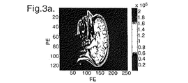
図3は画像に与える動きの影響を示している。図3aは最大解像度のMRI画像を示している。図3bは同じ画像であるが処理された変移を伴なった画像を示している。その変移は、DC+18のラインで導入されたものであって、1画素の周波数エンコード変移および−2画素の位相エンコード変移で構成される。この範例では1画素は約2mmである。形成された画像に与える影響は極めて顕著であって、移動を伴なった画像は明らかに、焦点集束および明確さで劣る。したがってそのような画像の診断的価値は、それ相応に下がる。 FIG. 3 shows the influence of motion on the image. FIG. 3a shows a maximum resolution MRI image. FIG. 3b shows the same image but with a processed transition. The transition is introduced in the DC + 18 line, and is composed of a frequency encoding transition of one pixel and a phase encoding transition of -2 pixels. In this example, one pixel is about 2 mm. The effect on the formed image is very significant, and the image with movement is clearly inferior in focus and clarity. Accordingly, the diagnostic value of such an image is correspondingly reduced.
ここで図2を参照すると、システム10の動作の機能ブロック図が示されている。コンピュータ38は、スキャナ12を制御してそこから情報を受け取り、ディスプレイ50上で画像を作成するためにこの情報を使用する。この画像は初期に再構成される画像である。初期画像が崩れているとシステム10の操作者が考える場合には、追加的な信号処理ルーチンが選択される。代わりに、さらなる信号処理が自動的に生じる可能性がある。いずれのケースでも、記憶された画像データは患者の動きの影響を削減するように処理される。
Referring now to FIG. 2, a functional block diagram of the operation of
本発明では、焦点合わせは、低い解像度の画像を焦点集束させ、その後、わずかに高い解像度へと進み、追加されるまさに新たなデータポイントに集中するという増加の手順によって実施される。患者の動きの量は、追加されたデータを予測されたデータと比較することによって決定される。 In the present invention, focusing is performed by an increasing procedure of focusing the low resolution image, then proceeding to a slightly higher resolution and focusing on just the new data points that are added. The amount of patient motion is determined by comparing the added data with the predicted data.
本発明の一実施形態では、わずかに高い解像度の画像は、低い解像度の画像に1つの追加の位相エンコードラインを加えることによって形成される。言い換えると、DCに対称的にまたがる2m+1の位相エンコードラインが考えられ、ここでmは小さい正の整数である。これらは位相エンコード空間周波数、またはk空間、ラインkであり、ここで−m≦k≦mであり、k=0でDCである。各々の位相エンコード(PE)ラインはn FE 個のデータポイントで構成され、すなわちそれらデータポイントは周波数エンコード方向で取られる。位相エンコードライン内のn FE 個のデータポイントは数ミリ秒で取得され、それゆえに普通では位相エンコードライン内部で有意の画像歪みが動きの影響から生じることはないであろう。 In one embodiment of the invention, a slightly higher resolution image is formed by adding one additional phase encode line to the lower resolution image. In other words, 2m + 1 phase encode lines that span DC symmetrically are conceivable, where m is a small positive integer. These are the phase encoding spatial frequencies, or k-space, line k, where -m ≦ k ≦ m, and k = 0 and DC. Each phase encode (PE) line is composed of n FE data points, i.e., the data points are taken in the frequency encode direction. The n FE data points in the phase encode line are acquired in a few milliseconds, so normally no significant image distortion will arise from the motion effects within the phase encode line.
n FE 個の点によるこの(2m+1)の第1のデータセットから、低い解像度の複素MRI画像I2m+1が普通の方式で二次元フーリエ変換(FT)によって形成されることが可能である。図4はこの方式で得られる低い解像度の画面の例を示している。図4aでは画像の焦点は合っており、図4bでは画像の焦点は合っていない。本発明に従った方法は帰納的であるので、低い解像度の画像は処理の早いステージで焦点合わせされる。一般的に、何らかの他の手段によって、或る数のPEラインを有する低い解像度の画像の焦点を合わせることによって処理に着手し、その後、本発明の方法を使用して一度に1つの位相エンコードラインを追加して画像を構築することが好ましい。 From this (2m + 1) first data set with n FE points, a low resolution complex MRI image I 2m + 1 can be formed by a two-dimensional Fourier transform (FT) in the usual manner. FIG. 4 shows an example of a low resolution screen obtained by this method. In FIG. 4a the image is in focus and in FIG. 4b the image is not in focus. Since the method according to the present invention is inductive, low resolution images are focused in the early stage of processing. In general, the process is undertaken by focusing some low resolution image with a certain number of PE lines by some other means, and then one phase encoding line at a time using the method of the present invention. It is preferable to construct an image by adding.
焦点の合ったI2m+1画像から、I2m+1よりもわずかに高い解像度の(2m+1)×nFE画像I2m+2が形成されることを想定する。この画像はPEラインkから成る生のK空間データ上の2DのFTによって得られ、ここで−m≦k≦m+1である。特に患者の未補償の動きがラインk=m+1で生じていた可能性があるので、一般にこの画像は焦点の合っていないものである可能性がある。前の画像の焦点が合っていたので、追加された新たなPEラインにのみ集中する必要がある。こうして、低い方の解像度の画像からわずかに高い解像度の画像へと画像が構築され、その目的は、最後の追加ラインについて最初はK空間のプラス側、その後マイナス側等々でδx(FE移動)、δy(PE移動)およびδθ(患者の角回転移動)を推定することである。一般則を損なうことなく、それらの移動は、K空間内のDCライン上の患者の何らかの「基準」位置に関すると考えられることが可能である。MRI画像の解像度増大として追加された新たなPEラインが必ずしも時間的に順番に取得されておらず、これが問題にならないことにやはり留意すべきである。PEラインのどのような通常の収集順序もあるであろう。ここではデカルト収集が記載されるが、しかし当業者によって理解されるであろうが、「ハーフフーリエ」または螺旋タイプの収集法も適切な変更を伴なって同様の方式で含まれることが可能である。 Assume that an in-focus I 2m + 1 image forms a (2m + 1) × n FE image I 2m + 2 with slightly higher resolution than I 2m + 1 . This image is obtained by 2D FT on raw K-space data consisting of PE line k, where -m≤k≤m + 1. In general, this image may be out of focus, as the patient's uncompensated motion may have occurred at line k = m + 1. Since the previous image was in focus, it is necessary to concentrate only on the new PE line added. In this way, an image is constructed from a lower resolution image to a slightly higher resolution image, the purpose of which is δx (FE movement) first on the positive side of K space, then on the negative side, etc. for the last additional line, δy ( PE movement) and δθ (patient angular rotation movement). Without compromising the general rule, their movement can be thought of as relating to some “reference” position of the patient on the DC line in K-space. It should also be noted that the new PE lines added as an increase in the resolution of the MRI image are not necessarily acquired sequentially in time, and this is not a problem. There will be any normal collection order of PE lines. Cartesian collection is described here, but as will be appreciated by those skilled in the art, “half Fourier” or spiral type collection methods can also be included in a similar manner with appropriate modifications. is there.
本方法は、前に焦点合わせされた画像I2m+1に関連する画像データから焦点の合った(2m+2)ラインの画像I2m+2への妥当な近似J2m+2を予測することが可能であることを基本として進行する。その予測はI2m+1に関連する生のk空間データで実行されることが可能である。しかしながら、図3の画像のk空間データの振幅と位相のプロットを示す図5から分かるように、生のk空間データは急速に変化する構造を有する可能性があり、それは予測を一層困難にする可能性がある。さらにk空間内のあらゆる点が画像内のあらゆる点に影響を与える。 This method has a basic that it is possible to predict a reasonable approximation J 2m + 2 from the front to the image data associated with the focused image I 2m + 1 in focus to (2m + 2) image I 2m + 2 line proceed. The prediction can be performed on raw k-space data associated with I 2m + 1 . However, as can be seen from FIG. 5, which shows a plot of the amplitude and phase of the k-space data of the image of FIG. 3, the raw k-space data can have a rapidly changing structure, which makes it more difficult to predict. there is a possibility. In addition, every point in k-space affects every point in the image.
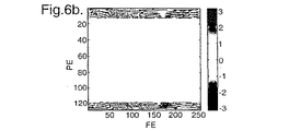
本実施形態では、予測はFE変換されたハイブリッド空間、すなわちk空間データ上で実行された。FE変換されたハイブリッド空間H2m+1は、FE方向に沿って生のk空間データ上でフーリエ変換を行なうことによって形成された。図6はm=11の場合にk空間データ上で形成されたハイブリッド空間を示している。ハイブリッド空間はk空間よりもいくぶん少なく変化し、それゆえに追加ラインを予測することはさらに容易である。さらに、このFE変換されたハイブリッド空間内の所定のFE位置にある更なるラインは、最終画像内の同じFE値にあるラインにマップし、それはハイブリッド空間の変化が二次元的であるよりも一次元的であることを意味し、やはりハイブリッド空間内の予測をさらに容易にする。 In the present embodiment, the prediction is performed on the FE-transformed hybrid space, that is, k-space data. The FE-transformed hybrid space H 2m + 1 was formed by performing a Fourier transform on the raw k-space data along the FE direction. FIG. 6 shows a hybrid space formed on the k-space data when m = 11. The hybrid space changes somewhat less than the k-space, so it is easier to predict additional lines. In addition, further lines at a given FE position in this FE transformed hybrid space map to lines at the same FE value in the final image, which is more linear than the change in hybrid space is two-dimensional. It means original and again makes predictions in hybrid space easier.
追加される次のラインはラインk=m+1である。m=11である図6に示した例については、次のラインはライン+12、すなわちDCラインの右に12のPEラインである。最も負のライン(ラインm=−11、DCの左へ11のライン)を1として数えると、追加される次のラインはライン(2m+2)=24である。このラインを予測するために、すべてのFE値でハイブリッド空間を通る断面が考慮される。図7は、図6に示したハイブリッド空間を通る特定のFE値にある断面の例を示している。図7aは実部を通る断面を示し、図7bは虚部の断面を示している。両方のケースでとられるFE値はFE=1であって、すなわちFE移動は1画素と仮定された。両方の図中で実線はI2m+2の焦点の合ったバージョンに関する実際の断面である。新たなデータポイントを予測するために、フィッティングアルゴリズムが(既に焦点の合っている)第1のハイブリッドデータセットに関連する最初の23の点に使用され、24番目を予測するために伸ばされる。ARMA級数を適合させることによって得られる可能性のある、予測された適合は点線で示される。ここで選択された特定のフィッティングと予測のアルゴリズムは、プロニーアルゴリズムであり、それは本例内の最初の23の点に自己回帰移動平均(ARMA)級数を適合させ(すなわち線形予測フィルタ)、その後、これを点24に外挿する。図7で実際の24番目の点が予測された点と比較するために示されていることに留意すべきである。予測された点が焦点の合った画像の24番目の点の値にほぼ近似していることを見て取ることが可能である。ここでは特定の線形予測アルゴリズムが指名されているけれども、なおもさらに適している可能性のある他の候補が存在する。さらに、線形のARMAタイプの予測よりも優れているなら、非線形の予測器が考えられることすら可能であろう。 The next line to be added is line k = m + 1. For the example shown in FIG. 6 where m = 11, the next line is line +12, ie, 12 PE lines to the right of the DC line. Counting the most negative lines (line m = -11, 11 lines to the left of DC) as 1, the next line added is line (2m + 2) = 24. To predict this line, the cross-section through the hybrid space is considered at all FE values. FIG. 7 shows an example of a cross section at a specific FE value passing through the hybrid space shown in FIG. 7a shows a cross section through the real part, and FIG. 7b shows a cross section of the imaginary part. The FE value taken in both cases was FE = 1, ie the FE movement was assumed to be 1 pixel. The solid line in both figures is the actual cross section for the focused version of I 2m + 2 . In order to predict a new data point, a fitting algorithm is used for the first 23 points associated with the first hybrid data set (which is already in focus) and extended to predict the 24th. The predicted fit that may be obtained by fitting the ARMA series is indicated by a dotted line. The particular fitting and prediction algorithm chosen here is the Plony algorithm, which fits the autoregressive moving average (ARMA) series to the first 23 points in this example (ie a linear prediction filter) and then This is extrapolated to point 24. Note that the actual 24th point is shown in FIG. 7 for comparison with the predicted point. It can be seen that the predicted point is approximately approximating the value of the 24th point in the focused image. Although a specific linear prediction algorithm is nominated here, there are other candidates that may still be more suitable. Furthermore, if it is better than linear ARMA type prediction, a non-linear predictor could even be considered.
最初の2m+1のPEラインから2m+2番目のラインへと前方に予測されたハイブリッド空間内の2m+2ラインを作り出すために、この処理はハイブリッド空間を通る各々の断面について異なるFE位置で繰り返される。 This process is repeated at a different FE location for each cross-section through the hybrid space to create a 2m + 2 line in the hybrid space predicted forward from the first 2m + 1 PE line to the 2m + 2 line.
そして、「予測された」2m+2ラインの画像J2m+2を作り出すためにPE方向に沿ってフーリエ変換を実行することが可能である。そのような予測された画像は、図8aに示される実際の焦点の合った画像との比較で図8bに示されている。画像はフーリエシフトされており、それゆえに、生およびハイブリッドの空間内で位相変化を最少限にするために、4の4分割として現れることに留意すべきである。画像は、視覚的に非常に近く現れるが、予測されて焦点合わせされた(2m+2)ラインの画像のK空間の位相が、ライン2m+2上のおそらく焦点の合っていない実際の画像の位相とそれを、意味を持って比較することが可能なように、十分に良好に振舞うことを立証するわけではない。それでもやはり、その位相がそのような比較に適していることはコンピュータシミュレーションによって示されている。
A Fourier transform can then be performed along the PE direction to produce a “predicted” 2m + 2 line image J 2m + 2 . Such a predicted image is shown in FIG. 8b in comparison with the actual focused image shown in FIG. 8a. It should be noted that the image is Fourier shifted and therefore appears as a quadrant of 4 in order to minimize phase changes in raw and hybrid space. The image appears very close visually, but the K-space phase of the predicted and focused (2m + 2) line image matches the phase of the possibly unfocused actual image on
特に、予測されて焦点合わせされた複素画像J2m+2は、逆2D FTを介して生のk空間形式J2m+2 rawへと変換される。そして、k空間に追加された焦点の合っていない実際の新たなラインの点毎の比が、断定されたk空間データJ2m+2 raw内の対応するラインを伴なって形成される。後者のラインはおそらく焦点の合っていないラインの予測であり、それに対してベクトル比の最初のラインは、FE移動に起因して直線的な位相変化を有する。したがって、予測が適切な場合には、この線形位相は2つのラインの点毎の比の中で識別可能であろう。実際では、ベクトル比がフーリエ変換される場合には、FE方向の動きに起因する線形位相は、ライン+m+1上で生じる、FE移動δxの量を与える(DCに関する)位置でスペクトルの最大値として検出可能であろう。右の場所で生じるそのようなスペクトル最大値の存在は、シミュレーションで検証されており、存在するPE移動の量と独立である。 In particular, the predicted and focused complex image J 2m + 2 is converted to the raw k-space format J 2m + 2 raw via an inverse 2D FT. A point-to-point ratio of the actual new line added to k-space that is out of focus is then formed with the corresponding line in the determined k-space data J 2m + 2 raw . The latter line is probably a prediction of an out-of-focus line, whereas the first line of vector ratio has a linear phase change due to FE movement. Thus, if the prediction is appropriate, this linear phase will be distinguishable in the point-to-point ratio of the two lines. In practice, when the vector ratio is Fourier transformed, the linear phase due to the movement in the FE direction is detected as the maximum value of the spectrum at the position (with respect to DC) giving rise to the amount of FE movement δx occurring on line + m + 1. It will be possible. The presence of such spectral maxima occurring at the right location has been verified by simulation and is independent of the amount of PE migration present.
いったん周波数エンコード方向のいかなる移動の程度も決定されると、PE移動の量を直接的に推定することが必要とされる。最初に、ちょうど決定されたいかなるFE移動に関するk空間データも補償する。そして、DC+m+1にある新たなPEラインで、焦点の合っていない実際の画像I2m+2に関するハイブリッド空間の位相を焦点の合った予測された画像の位相と比較する。上述したようなFE移動の決定については、この比較はすべてのFE位置にわたって為される。その結果は複素数のベクトルであり、そしてそれはPE移動δyに起因する位相オフセットのさらに優れた推定値を与えるために、位相がとられる前に平均化される。当業者によく知られ、かつ容易に導き出されるように、位相オフセットは理論的に2π.δy.(m+1)/nPEで与えられ、ここでnPEは最大解像度画像のPEラインの数であり、δyはPE移動である。こうして、位相オフセットはPE方向のいかなる移動の程度も与えるために使用されることが可能である。そして、k空間データがいかなるそのような移動について補償されることが可能であり、データセットは、いかなるPEもしくはFEの平行移動についても焦点合わせされる。 Once any degree of movement in the frequency encoding direction is determined, it is necessary to directly estimate the amount of PE movement. First, it compensates k-space data for any FE movement just determined. The new PE line at DC + m + 1 then compares the phase of the hybrid space for the actual image I 2m + 2 that is not in focus with the phase of the predicted image that is in focus. For the determination of FE movement as described above, this comparison is made across all FE positions. The result is a complex vector, which is averaged before the phase is taken to give a better estimate of the phase offset due to PE movement δy. As is well known to those skilled in the art and easily derived, the phase offset is theoretically 2π. δy. (M + 1) / nPE, where nPE is the number of PE lines in the maximum resolution image and δy is the PE movement. Thus, the phase offset can be used to provide any degree of movement in the PE direction. The k-space data can then be compensated for any such movement, and the data set is focused for any PE or FE translation.
PE移動を決定するために複素ベクトルを平均化することの代替選択肢として、上述のようにして得られるFEスペクトルの最大値の位相が使用される可能性がある。PEの位相に与えるモジュロ2πの影響が高めの空間周波数で生じて存在するときに、これは好ましい可能性がある。 As an alternative to averaging complex vectors to determine PE movement, the maximum phase of the FE spectrum obtained as described above may be used. This may be preferred when the modulo 2π effect on the PE phase occurs and exists at higher spatial frequencies.
PEとFEの移動を決定したとき、画像内の画像の回転を決定することが可能である。回転の量は、予測されたデータラインを使用して形成された画像を実際のデータラインを使用して形成された画像と比較することによって判定されることが好都合である。2つの画像の比較から、追加ライン上の回転の程度が決定されることが可能である。 When the movement of PE and FE is determined, it is possible to determine the rotation of the image within the image. The amount of rotation is conveniently determined by comparing an image formed using the predicted data line with an image formed using the actual data line. From the comparison of the two images, the degree of rotation on the additional line can be determined.
2m+2ラインの焦点の合った低解像度の画像に到達したとき、この画像はDCの負の側でk0=−m−1でPEラインを追加するため、および同様の予測処理をK空間の負の側で実行するための出発点と使用される、すなわち新たに焦点合わせした画像を第1のデータセットとして設定することが可能である。このステップに続いて、処理全体が再び繰り返されることが可能であるが、しかし元々の出発点であった2m+1ラインの焦点の合った画像の代わりにわずかに高い解像度の2m+3ラインの焦点の合った画像で出発する。したがって、全体の手順は、低い解像度の画像から高い解像度へと徐々に進みながら帰納的に繰り返される。 When a focused low resolution image of 2m + 2 lines is reached, this image adds a PE line with k0 = −m−1 on the negative side of DC, and a similar prediction process is used for negative in K space. It is possible to set the first data set to be the starting point for execution on the side, ie the newly focused image. Following this step, the entire process can be repeated again, but with a slightly higher resolution 2m + 3 line focused instead of the original 2m + 1 line focused image. Start with images. Thus, the entire procedure is iteratively repeated while gradually progressing from a low resolution image to a high resolution.
したがって本発明の一実施形態では、手順は典型的には以下のように進行することが可能である。
i)焦点の合った第1の画像に対応するいくつかの位相エンコードラインの第1のデータセットをとり、
ii)第1のデータセットの一方の側にラインを追加して第2のデータセットを形成し、
iii)第1のデータセットで1DのFTを行なってハイブリッド空間の第1のデータセットを形成し、
iv)ハイブリッド空間の第1のデータセットを通る断面を特定のFEの値でとり、追加される次の複素データポイントを予測するためにフィッティングアルゴリズムを使用し、
v)ハイブリッド空間内に予測された追加ラインを形成するためにFEのすべての値についてステップ(iv)を繰り返し、
vi)ハイブリッド空間の第1のデータセットおよび予測された追加ラインを変換して予測されたk空間の追加ラインを形成し、
vii)予測されたk空間の追加ラインと実際のk空間の追加ラインとの点毎の比を形成し、線形位相シフトを決定し、
viii)線形位相シフトを補償するために実際のk空間の追加ラインを補正し、
ix)補正されたk空間のデータにFTを行ないハイブリッド空間のデータセットを形成し、
x)ハイブリッド空間のデータセットの予測されたラインをハイブリッド空間内の補正された追加ラインと比較し、位相のオフセットを決定し、
xi)決定された位相オフセットを補正するためにk空間データを補正し、
xii)最大の解像度が達成されるまでステップ(i)から(xi)を繰り返して充分に補正されたk空間のデータセットを新たな第1のデータセットとしてとる。
Thus, in one embodiment of the present invention, the procedure can typically proceed as follows.
i) Take a first data set of several phase encode lines corresponding to the first image in focus;
ii) adding a line to one side of the first data set to form a second data set;
iii) performing a 1D FT on the first data set to form a first data set in hybrid space;
iv) take a cross-section through the first data set in hybrid space at a specific FE value and use a fitting algorithm to predict the next complex data point to be added;
v) Repeat step (iv) for all values of FE to form predicted additional lines in the hybrid space,
vi) transforming the first dataset in hybrid space and the predicted additional line to form an additional line in the predicted k-space;
vii) forming a point-to-point ratio between the predicted additional line in k-space and the actual additional line in k-space to determine a linear phase shift;
viii) correct additional lines in the actual k-space to compensate for the linear phase shift;
ix) FT is performed on the corrected k-space data to form a hybrid space data set;
x) comparing the predicted line of the hybrid space dataset with the corrected additional line in the hybrid space to determine the phase offset;
xi) correct the k-space data to correct the determined phase offset;
xii) Repeat steps (i) to (xi) until the maximum resolution is achieved, and take a fully corrected k-space data set as the new first data set.
本発明は、或る特定の収集仕組みと予測手段に関連して、以上に説明されてきた。しかしながら、当業者は、本発明の本質から逸脱することなく他の仕組みおよび予測が使用される可能性があることに気付くであろう。 The present invention has been described above with reference to certain collection mechanisms and prediction means. However, one of ordinary skill in the art will realize that other mechanisms and predictions may be used without departing from the essence of the present invention.
Claims (27)
a)磁気共鳴映像法(MRI)の走査から得られるいくつかのデータポイントを含むk空間の画像データセットを画定するステップ、
b)k空間の画像データポイントのいくつかから第1のデータセットを形成するステップ、
c)第1のデータセットよりも高い画像の解像度に対応する第2のデータセットを形成するために第1のデータセットにデータを追加するステップ、
d)第1のデータセットに基づいて追加されたデータを予測するために予測アルゴリズムを使用するステップであって予測されたデータを提供するステップ、
e)望ましくない動きを決定するために追加されたデータを予測されたデータと比較するステップ、
f)望ましくない動きに関する第2のデータセットを補償し、補正されたデータセットを得るために追加されたデータを補正するステップ、および
g)補正されたデータセットを第1のデータセットとして処理し、そして累進的に解像度を増加させ、走査された物体の動きの補正された画像を得るためにステップc)からg)を繰り返すステップを含む方法。A method of operating a magnetic resonance imaging (MRI) system that creates an image of the scanned object corrected for artifacts introduced by unwanted movement of the object during magnetic resonance imaging (MRI) scanning, comprising:
a) defining a k-space image data set comprising a number of data points obtained from a magnetic resonance imaging (MRI) scan;
b) forming a first data set from some of the k-space image data points;
c) adding data to the first data set to form a second data set corresponding to a higher image resolution than the first data set;
d) using a prediction algorithm to predict the added data based on the first data set, providing the predicted data;
e) comparing the added data with the predicted data to determine undesirable movements;
f) compensating the second data set for unwanted motion and correcting the added data to obtain a corrected data set; and g) processing the corrected data set as the first data set. And repeating steps c) to g) to progressively increase the resolution and obtain a corrected image of the scanned object motion.
a)ハイブリッド空間のデータセットを形成するために第1のk空間のデータセットに周波数エンコード方向に沿って一次元(1D)フーリエ変換を行うステップ、
b)ハイブリッド空間データの次のラインを予測するためにハイブリッド空間のデータセットを分析するステップ、
c)k空間内に予測されたラインを供給するためにハイブリッド空間データと予測されたラインとをk空間内に変換するステップ、
d)追加された実際のk空間ラインに対する前記予測されたk空間ラインの点毎の比を形成するステップ、および、
e)実際と予測のライン間の線形位相変化の量をFE方向での移動の推定値として決定するステップによって決定される請求項1から7のいずれか一項に記載の方法。Movement in the frequency encoding direction
a) performing a one-dimensional (1D) Fourier transform along the frequency encoding direction on the first k-space data set to form a hybrid space data set;
b) analyzing the hybrid space data set to predict the next line of hybrid space data;
c) transforming the hybrid space data and the predicted line into k-space to provide a predicted line in k-space;
d) forming a point-to-point ratio of the predicted k-space line to the added actual k-space line; and
8. A method according to any one of claims 1 to 7, determined by e) determining the amount of linear phase change between the actual and predicted lines as an estimate of the movement in the FE direction.
a)データポイントを生成するために物体を走査するMRI画像手段、および
b)i)磁気共鳴映像法(MRI)の走査から得られるいくつかのデータポイントを含むk空間の画像データセットを画定し、
ii)k空間の画像データポイントのいくつかから第1のデータセットを形成し、
iii)第1のデータセットよりも高い画像の解像度に対応する第2のデータセットを形成するために第1のデータセットにデータを追加し、
iv)第1のデータセットに基づいて追加されたデータを予測するために予測アルゴリズムを使用するステップであって予測されたデータを提供し、
v)望ましくない動きを決定するために追加されたデータを予測されたデータと比較し、
vi)望ましくない動きに関する第2のデータセットを補償するために追加された補正し、補正されたデータセットを生成し、および
vii)補正されたデータセットを第1のデータセットとして処理し、そして累進的に解像度を増加させ、走査された物体の動きの補正された画像を得るためにステップiii)からvii)を繰り返すようにプログラムされたコンピュータ手段を含む磁気共鳴映像(MRI)システム。A magnetic resonance imaging (MRI) system for creating an image of the scanned object corrected for artifacts introduced by unwanted movement of the object during magnetic resonance imaging (MRI) scanning,
a) MRI image means for scanning an object to generate data points; and b) i) an image data set in k-space that includes a number of data points obtained from a magnetic resonance imaging (MRI) scan. ,
ii) forming a first data set from some of the image data points in k-space;
iii) adding data to the first data set to form a second data set corresponding to a higher image resolution than the first data set;
iv) using the prediction algorithm to predict the added data based on the first data set, providing the predicted data;
v) compare the data added to determine undesirable movement with the predicted data;
vi) a correction added to compensate for the second data set for undesirable motion, generating a corrected data set, and vii) treating the corrected data set as the first data set, and A magnetic resonance imaging (MRI) system comprising computer means programmed to repeat steps iii) to vii) to progressively increase resolution and obtain a corrected image of scanned object motion.
a)ハイブリッド空間のデータセットを形成するために第1のk空間のデータセットに周波数エンコード方向に沿って一次元(1D)フーリエ変換を行うステップ、
b)ハイブリッド空間データの次のラインを予測するためにハイブリッド空間のデータセットを分析するステップ、
c)k空間内に予測されたラインを供給するためにハイブリッド空間データと予測されたラインとをk空間内に変換するステップ、
d)追加された実際のk空間ラインに対する前記予測されたk空間ラインの点毎の比を形成するステップ、および、
e)実際と予測のライン間の線形位相変化の量をFE方向での移動の推定値として決定するステップによって、周波数エンコード方向での移動を決定するようにプログラムする請求項15から26のいずれか一項に記載の磁気共鳴映像(MRI)システム。Computer means
a) performing a one-dimensional (1D) Fourier transform along the frequency encoding direction on the first k-space data set to form a hybrid space data set;
b) analyzing the hybrid space data set to predict the next line of hybrid space data;
c) transforming the hybrid space data and the predicted line into k-space to provide a predicted line in k-space;
d) forming a point-to-point ratio of the predicted k-space line to the added actual k-space line; and
27. Any one of claims 15 to 26, programmed to determine movement in the frequency encoding direction by e) determining the amount of linear phase change between the actual and predicted lines as an estimate of movement in the FE direction. The magnetic resonance imaging (MRI) system according to one item.
Applications Claiming Priority (2)
| Application Number | Priority Date | Filing Date | Title |
|---|---|---|---|
| GBGB0129465.1A GB0129465D0 (en) | 2001-12-08 | 2001-12-08 | Method for compensating for effects of object motion in an image |
| PCT/GB2002/005528 WO2003050761A2 (en) | 2001-12-08 | 2002-12-05 | Method for compensating for motion artifacts in magnetic resonance imaging by phase line prediction |
Publications (3)
| Publication Number | Publication Date |
|---|---|
| JP2005511224A JP2005511224A (en) | 2005-04-28 |
| JP2005511224A5 JP2005511224A5 (en) | 2006-01-05 |
| JP4481648B2 true JP4481648B2 (en) | 2010-06-16 |
Family
ID=9927298
Family Applications (1)
| Application Number | Title | Priority Date | Filing Date |
|---|---|---|---|
| JP2003551742A Expired - Fee Related JP4481648B2 (en) | 2001-12-08 | 2002-12-05 | A method for compensating for the effects of object motion in an image |
Country Status (9)
| Country | Link |
|---|---|
| US (1) | US6777933B2 (en) |
| EP (1) | EP1451777B1 (en) |
| JP (1) | JP4481648B2 (en) |
| AT (1) | ATE317576T1 (en) |
| AU (1) | AU2002347356A1 (en) |
| CA (1) | CA2469031A1 (en) |
| DE (1) | DE60209141T2 (en) |
| GB (1) | GB0129465D0 (en) |
| WO (1) | WO2003050761A2 (en) |
Families Citing this family (20)
| Publication number | Priority date | Publication date | Assignee | Title |
|---|---|---|---|---|
| JP5105848B2 (en) * | 2006-02-06 | 2012-12-26 | 株式会社東芝 | Magnetic resonance imaging apparatus and imaging condition setting method in magnetic resonance imaging apparatus |
| WO2007124450A2 (en) * | 2006-04-21 | 2007-11-01 | The Trustees Of The University Of Pennsylvania | Motion artifact compensation |
| ES2569411T3 (en) | 2006-05-19 | 2016-05-10 | The Queen's Medical Center | Motion tracking system for adaptive real-time imaging and spectroscopy |
| WO2008126017A2 (en) * | 2007-04-12 | 2008-10-23 | Koninklijke Philips Electronics N.V. | Motion corrected multinuclear magnetic resonance imaging |
| EP2142090A4 (en) * | 2007-05-04 | 2011-07-20 | California Inst Of Techn | Low field squid mri devices, components and methods |
| US20090322324A1 (en) * | 2007-05-04 | 2009-12-31 | Penanen Konstantin I | Geometries for superconducting sensing coils for squid-based systems |
| JP5105586B2 (en) * | 2007-05-11 | 2012-12-26 | 株式会社日立メディコ | Magnetic resonance imaging system |
| US20110009731A1 (en) | 2009-07-08 | 2011-01-13 | Fonar Corporation | Method and system for performing upright magnetic resonance imaging of various anatomical and physiological conditions |
| US8934691B2 (en) | 2011-04-06 | 2015-01-13 | Siemens Medical Solutions Usa, Inc. | System for motion compensated MR parallel imaging |
| US9606209B2 (en) | 2011-08-26 | 2017-03-28 | Kineticor, Inc. | Methods, systems, and devices for intra-scan motion correction |
| US9305365B2 (en) | 2013-01-24 | 2016-04-05 | Kineticor, Inc. | Systems, devices, and methods for tracking moving targets |
| US9717461B2 (en) | 2013-01-24 | 2017-08-01 | Kineticor, Inc. | Systems, devices, and methods for tracking and compensating for patient motion during a medical imaging scan |
| US10327708B2 (en) | 2013-01-24 | 2019-06-25 | Kineticor, Inc. | Systems, devices, and methods for tracking and compensating for patient motion during a medical imaging scan |
| CN105392423B (en) | 2013-02-01 | 2018-08-17 | 凯内蒂科尔股份有限公司 | The motion tracking system of real-time adaptive motion compensation in biomedical imaging |
| CN106572810A (en) | 2014-03-24 | 2017-04-19 | 凯内蒂科尔股份有限公司 | Systems, methods, and devices for removing prospective motion correction from medical imaging scans |
| CN106714681A (en) | 2014-07-23 | 2017-05-24 | 凯内蒂科尔股份有限公司 | Systems, devices, and methods for tracking and compensating for patient motion during a medical imaging scan |
| CN107211146A (en) * | 2014-11-21 | 2017-09-26 | Vid拓展公司 | One-dimensional transform pattern and coefficient scanning order |
| US9943247B2 (en) | 2015-07-28 | 2018-04-17 | The University Of Hawai'i | Systems, devices, and methods for detecting false movements for motion correction during a medical imaging scan |
| US10716515B2 (en) | 2015-11-23 | 2020-07-21 | Kineticor, Inc. | Systems, devices, and methods for tracking and compensating for patient motion during a medical imaging scan |
| US10551458B2 (en) | 2017-06-29 | 2020-02-04 | General Electric Company | Method and systems for iteratively reconstructing multi-shot, multi-acquisition MRI data |
Family Cites Families (7)
| Publication number | Priority date | Publication date | Assignee | Title |
|---|---|---|---|---|
| US5051903A (en) * | 1989-08-14 | 1991-09-24 | General Electric Company | Method and apparatus for predicting values of a varying periodic phenomenon |
| JPH05154130A (en) * | 1991-12-06 | 1993-06-22 | Hitachi Ltd | Body motion artifact eliminating method |
| GB9614407D0 (en) * | 1996-07-09 | 1996-09-04 | Secr Defence | Method for imaging artefact reduction |
| DE19647537A1 (en) * | 1996-11-16 | 1998-05-20 | Philips Patentverwaltung | MR method for reducing movement artifacts and arrangement for carrying out the method |
| US6114852A (en) * | 1999-01-23 | 2000-09-05 | General Electric Company | Method employing point source to determine motion induced errors in MR imaging |
| DE10029592A1 (en) * | 2000-06-15 | 2001-12-20 | Philips Corp Intellectual Pty | MR imaging with motion compensation |
| US6675034B2 (en) * | 2001-04-19 | 2004-01-06 | Sunnybrook And Women's Health Sciences Centre | Magnetic resonance imaging using direct, continuous real-time imaging for motion compensation |
-
2001
- 2001-12-08 GB GBGB0129465.1A patent/GB0129465D0/en not_active Ceased
-
2002
- 2002-12-05 EP EP02783291A patent/EP1451777B1/en not_active Expired - Lifetime
- 2002-12-05 CA CA002469031A patent/CA2469031A1/en not_active Abandoned
- 2002-12-05 DE DE60209141T patent/DE60209141T2/en not_active Expired - Lifetime
- 2002-12-05 WO PCT/GB2002/005528 patent/WO2003050761A2/en active IP Right Grant
- 2002-12-05 AT AT02783291T patent/ATE317576T1/en not_active IP Right Cessation
- 2002-12-05 AU AU2002347356A patent/AU2002347356A1/en not_active Abandoned
- 2002-12-05 JP JP2003551742A patent/JP4481648B2/en not_active Expired - Fee Related
- 2002-12-06 US US10/313,014 patent/US6777933B2/en not_active Expired - Lifetime
Also Published As
| Publication number | Publication date |
|---|---|
| GB0129465D0 (en) | 2002-01-30 |
| AU2002347356A8 (en) | 2003-06-23 |
| JP2005511224A (en) | 2005-04-28 |
| US20030130574A1 (en) | 2003-07-10 |
| WO2003050761A2 (en) | 2003-06-19 |
| AU2002347356A1 (en) | 2003-06-23 |
| WO2003050761A3 (en) | 2003-12-04 |
| US6777933B2 (en) | 2004-08-17 |
| ATE317576T1 (en) | 2006-02-15 |
| DE60209141D1 (en) | 2006-04-20 |
| CA2469031A1 (en) | 2003-06-19 |
| EP1451777A2 (en) | 2004-09-01 |
| EP1451777B1 (en) | 2006-02-08 |
| DE60209141T2 (en) | 2006-10-26 |
Similar Documents
| Publication | Publication Date | Title |
|---|---|---|
| JP4481648B2 (en) | A method for compensating for the effects of object motion in an image | |
| JP4176835B2 (en) | Artifact reduced image generator | |
| JP5960163B2 (en) | Parallel MRI method for rigid body motion compensation using calibration scan, coil sensitivity map and navigator | |
| JP3976684B2 (en) | Method and apparatus for reducing the effects of motion in images | |
| JP6037652B2 (en) | Diffusion-weighted magnetic resonance data generation method, magnetic resonance system, and computer-readable storage medium | |
| JP3734086B2 (en) | Nuclear magnetic resonance imaging system | |
| EP0529527A1 (en) | Method and apparatus for high speed magnetic resonance imaging with improved image quality | |
| JP2014508622A (en) | MR image reconstruction using regularization constrained by prior information | |
| JP4481649B2 (en) | Method for compensating for the effects of object motion during MRI | |
| JP4118108B2 (en) | Improved method of sensitivity encoding MRI collection | |
| KR100335833B1 (en) | MR imaging device | |
| CN107810425B (en) | Eliminating non-T2Weighting the T of the signal contribution2Weighted MR imaging | |
| EP1094331A2 (en) | Mri apparatus | |
| JP4481591B2 (en) | Method, system and computer product for gradient nonlinearity k-space correction | |
| WO2020173688A1 (en) | Epi mr imaging with distortion correction | |
| US20230400545A1 (en) | Spin echo mr imaging with spiral acquisition | |
| US20240094320A1 (en) | Dixon-type water/fat separation mr imaging | |
| US20230036285A1 (en) | Magnetic resonance imaging system and method, and computer-readable storage medium | |
| US20040064033A1 (en) | System and method for reconstructing k-space data | |
| JP2006136736A (en) | Magnetic resonance imaging apparatus |
Legal Events
| Date | Code | Title | Description |
|---|---|---|---|
| A521 | Request for written amendment filed |
Free format text: JAPANESE INTERMEDIATE CODE: A523 Effective date: 20051027 |
|
| A621 | Written request for application examination |
Free format text: JAPANESE INTERMEDIATE CODE: A621 Effective date: 20051027 |
|
| A977 | Report on retrieval |
Free format text: JAPANESE INTERMEDIATE CODE: A971007 Effective date: 20080828 |
|
| A131 | Notification of reasons for refusal |
Free format text: JAPANESE INTERMEDIATE CODE: A131 Effective date: 20081104 |
|
| A601 | Written request for extension of time |
Free format text: JAPANESE INTERMEDIATE CODE: A601 Effective date: 20081224 |
|
| A602 | Written permission of extension of time |
Free format text: JAPANESE INTERMEDIATE CODE: A602 Effective date: 20090107 |
|
| A521 | Request for written amendment filed |
Free format text: JAPANESE INTERMEDIATE CODE: A523 Effective date: 20090501 |
|
| A131 | Notification of reasons for refusal |
Free format text: JAPANESE INTERMEDIATE CODE: A131 Effective date: 20090707 |
|
| A601 | Written request for extension of time |
Free format text: JAPANESE INTERMEDIATE CODE: A601 Effective date: 20090904 |
|
| A602 | Written permission of extension of time |
Free format text: JAPANESE INTERMEDIATE CODE: A602 Effective date: 20090911 |
|
| A521 | Request for written amendment filed |
Free format text: JAPANESE INTERMEDIATE CODE: A523 Effective date: 20091109 |
|
| TRDD | Decision of grant or rejection written | ||
| A01 | Written decision to grant a patent or to grant a registration (utility model) |
Free format text: JAPANESE INTERMEDIATE CODE: A01 Effective date: 20100302 |
|
| A01 | Written decision to grant a patent or to grant a registration (utility model) |
Free format text: JAPANESE INTERMEDIATE CODE: A01 |
|
| A61 | First payment of annual fees (during grant procedure) |
Free format text: JAPANESE INTERMEDIATE CODE: A61 Effective date: 20100318 |
|
| FPAY | Renewal fee payment (event date is renewal date of database) |
Free format text: PAYMENT UNTIL: 20130326 Year of fee payment: 3 |
|
| R150 | Certificate of patent or registration of utility model |
Ref document number: 4481648 Country of ref document: JP Free format text: JAPANESE INTERMEDIATE CODE: R150 Free format text: JAPANESE INTERMEDIATE CODE: R150 |
|
| FPAY | Renewal fee payment (event date is renewal date of database) |
Free format text: PAYMENT UNTIL: 20140326 Year of fee payment: 4 |
|
| R250 | Receipt of annual fees |
Free format text: JAPANESE INTERMEDIATE CODE: R250 |
|
| R250 | Receipt of annual fees |
Free format text: JAPANESE INTERMEDIATE CODE: R250 |
|
| R250 | Receipt of annual fees |
Free format text: JAPANESE INTERMEDIATE CODE: R250 |
|
| R250 | Receipt of annual fees |
Free format text: JAPANESE INTERMEDIATE CODE: R250 |
|
| R250 | Receipt of annual fees |
Free format text: JAPANESE INTERMEDIATE CODE: R250 |
|
| R250 | Receipt of annual fees |
Free format text: JAPANESE INTERMEDIATE CODE: R250 |
|
| LAPS | Cancellation because of no payment of annual fees |