JP4480992B2 - Electrical stimulator with balance adjustment function - Google Patents
Electrical stimulator with balance adjustment function Download PDFInfo
- Publication number
- JP4480992B2 JP4480992B2 JP2003410292A JP2003410292A JP4480992B2 JP 4480992 B2 JP4480992 B2 JP 4480992B2 JP 2003410292 A JP2003410292 A JP 2003410292A JP 2003410292 A JP2003410292 A JP 2003410292A JP 4480992 B2 JP4480992 B2 JP 4480992B2
- Authority
- JP
- Japan
- Prior art keywords
- output
- unit
- stimulation
- frequency
- electrical stimulation
- Prior art date
- Legal status (The legal status is an assumption and is not a legal conclusion. Google has not performed a legal analysis and makes no representation as to the accuracy of the status listed.)
- Expired - Lifetime
Links
- 230000000638 stimulation Effects 0.000 claims description 64
- 238000001514 detection method Methods 0.000 claims description 11
- 238000000034 method Methods 0.000 description 7
- 230000004936 stimulating effect Effects 0.000 description 4
- 238000010586 diagram Methods 0.000 description 2
- 230000007274 generation of a signal involved in cell-cell signaling Effects 0.000 description 2
- 230000001225 therapeutic effect Effects 0.000 description 2
- 230000003321 amplification Effects 0.000 description 1
- 238000007796 conventional method Methods 0.000 description 1
- 230000004118 muscle contraction Effects 0.000 description 1
- 238000003199 nucleic acid amplification method Methods 0.000 description 1
Images


Description
本発明は、周波数や波形などの電気刺激条件を変化させながら生体を刺激する、複数の出力系統を有する電気刺激装置の、出力電流バランスの調節に関するものである。 The present invention relates to adjustment of an output current balance of an electrical stimulation apparatus having a plurality of output systems that stimulates a living body while changing electrical stimulation conditions such as frequency and waveform.
従来の電気刺激装置は、刺激信号発生部、出力部、電極、制御部などから構成され、刺激信号発生部で矩形波や指数関数波や正弦波などの所定波形の、所定周波数の電気刺激信号を発生し、出力部で電気刺激信号の強さを所定の値に増幅し、電極を介して装置の出力を生体に供給する。
電気刺激装置は複数の出力を有する多チャンネル型も多く使用されている。このタイプの刺激装置は、複数の人を刺激する場合もあるが、一人に複数の電流を同時に流して刺激する場合もある。特に干渉低周波治療器は、2つ以上の電流を交差するように同時に通電し、生体内部で干渉波を発生させて刺激するものである。
A conventional electrical stimulation device includes a stimulation signal generation unit, an output unit, an electrode, a control unit, and the like. The stimulation signal generation unit has an electrical stimulation signal having a predetermined frequency such as a rectangular wave, an exponential wave, or a sine wave. The intensity of the electrical stimulation signal is amplified to a predetermined value at the output unit, and the output of the device is supplied to the living body via the electrode.
As the electrical stimulation apparatus, a multi-channel type having a plurality of outputs is often used. This type of stimulation apparatus may stimulate a plurality of people, but may also stimulate a person by simultaneously applying a plurality of currents. In particular, the interference low-frequency treatment device energizes two or more currents simultaneously so as to cross each other and generates an interference wave inside the living body to stimulate it.
一人に複数の電流を同時に流して刺激する場合、生体のインピーダンスは部位によって、また時間経過によって変化するので、刺激強度が変わることがある。このため、各電流のバランスをとって、刺激をおこなう。具体的には、各出力の刺激強度を調節して適度の刺激をおこなう。
しかし、この出力調節をマニュアルでおこなおうとすると、設定時及び時間経過とともに行わなければならないため、面倒である。これを解決するため、各出力の電流量を自動的にバランスさせるようにしているものもある(例えば特許文献1と2参照)。
以下に、これらの技術を図面で説明する。
However, if this output adjustment is performed manually, it must be performed at the time of setting and over time, which is troublesome. In order to solve this problem, there is one that automatically balances the amount of current of each output (see, for example, Patent Documents 1 and 2).
Hereinafter, these techniques will be described with reference to the drawings.
図2は特許文献1に記載されている図である。装置は2チャンネルの低周波治療器で、2つの出力を同時に用いて刺激する場合、図2のような割合で使用するという例を示している。
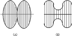
図3は特許文献2に記載されている図である。装置は、2つの正弦波の中周波電流を患部で交差するように同時に流し、体の内部で発生する干渉波を利用して生体を刺激する、干渉低周波治療器である。振幅が同じで周波数が僅かに異なる2つの電流を同時に流すと、図4(A)のような、干渉波を得ることができる。振幅(電流の強さ)が異なると、図4(B)のように、干渉波の節がゼロにならない不完全な干渉波が得られる。不完全な干渉波では十分な筋収縮が得られず、治療効果は低下する。このため、2つの電流をバランスさせて、治療効果を高くするように操作される。これを自動化したのが特許文献2である。これに対して、干渉低周波治療器では、故意にバランスを崩し、所望の位置を強く刺激する技術もあり、これを利用して刺激点をスイープさせることもできる。
一方、電気刺激装置では周波数や刺激波形を変化させながら刺激をおこなう技術も使用されている。例えば、特許公報2929556には周波数を1000〜10000Hz程度の範囲で変化させる技術が開示されている。
FIG. 2 is a diagram described in Patent Document 1. The device is a two-channel low-frequency treatment device, and when stimulating using two outputs at the same time, the device is used at the rate shown in FIG.
FIG. 3 is a diagram described in Patent Document 2. The device is an interference low-frequency treatment device that simultaneously applies two sine wave medium-frequency currents so as to intersect each other in an affected area, and stimulates a living body using interference waves generated inside the body. When two currents having the same amplitude and slightly different frequencies are supplied simultaneously, an interference wave as shown in FIG. 4A can be obtained. When the amplitude (current intensity) is different, an incomplete interference wave in which the node of the interference wave does not become zero is obtained as shown in FIG. 4B. Incomplete interference waves do not provide sufficient muscle contraction, reducing the therapeutic effect. For this reason, the two currents are balanced so that the therapeutic effect is enhanced. This is automated in Patent Document 2. On the other hand, in the interference low-frequency treatment device, there is also a technique for intentionally breaking the balance and strongly stimulating a desired position, and the stimulation point can be swept using this technology.
On the other hand, in the electrical stimulation apparatus, a technique for performing stimulation while changing the frequency and the stimulation waveform is also used. For example, Japanese Patent Publication 2929556 discloses a technique for changing the frequency in a range of about 1000 to 10,000 Hz.
特許文献1と特許文献2には、2つの電流を所定の比率にする技術と、2つの電流を自動的にバランスさせる技術が示されている。
しかし、これら従来技術は、周波数や波形はほぼ一定の場合に使用できるものである。最近は、特許公報2929556のように、周波数を大きく変化させる装置も使用されている。周波数が変化すると生体のインピーダンスも変化し、電流も大きく変化し、電流バランスが崩れて刺激が弱くなることがある。
しかし、周波数や刺激波形がダイナミックに変化するとき、これを勘案して電流を所定の比率にバランスさせる技術は存在しなかった。本出願はこれを解決するものである。
Patent Document 1 and Patent Document 2 disclose a technique for setting two currents to a predetermined ratio and a technique for automatically balancing the two currents.
However, these conventional techniques can be used when the frequency and waveform are substantially constant. Recently, an apparatus that greatly changes the frequency, such as Japanese Patent Publication 2929556, has been used. When the frequency changes, the impedance of the living body also changes, the current also changes greatly, the current balance may be lost, and the stimulation may be weakened.
However, there has been no technique for balancing the current to a predetermined ratio in consideration of this when the frequency and the stimulation waveform change dynamically. The present application solves this.
請求項1記載の発明では、
電気刺激信号を発生し所定の値に増幅する出力部(1)と、
前記出力部(1)の出力を検出する出力検出部(2)と、
前記出力部(1)の出力を生体に供給する電極(3)と、
を有する出力系統を複数設けるとともに、
前記の各出力部(1)の出力を制御する制御部(4)を設け、
前記制御部(4)で前記出力部(1)を制御して前記電気刺激信号の周波数と波形及び出力の強さを変化させて電気刺激をおこないながら前記の各出力部(1)の出力を検出する電気刺激装置において、
治療開始時に、出力設定キーを操作して前記各出力部(1)の出力を適切な強さに設定して各検出部(2)で前記各出力部(1)の出力を検出し、
刺激中に、検出部(2)で前記各出力部(1)の出力を検出し、刺激中の前記各出力部(1)の出力の強さの比が、治療開始時に得た前記各出力部(1)の出力の強さの比と同じになるように、前記制御部(4)で前記の各出力部(1)を制御するようにした。
In invention of Claim 1,
An output unit (1) for generating an electrical stimulation signal and amplifying it to a predetermined value;
An output detector (2) for detecting the output of the output unit (1);
An electrode (3) for supplying the output of the output unit (1) to a living body;
A plurality of output systems having
Provide a control unit (4) for controlling the output of each output unit (1),
The control unit (4) controls the output unit (1) to change the frequency and waveform of the electrical stimulation signal and the intensity of the output while performing electrical stimulation, and outputs each output unit (1). In the electrical stimulation device to detect,
At the start of treatment, operate the output setting key to set the output of each output unit (1) to an appropriate strength and detect the output of each output unit (1) with each detection unit (2) ,
During stimulation, the output of each output unit (1) is detected by the detection unit (2), and the output intensity ratio of each output unit (1) during stimulation is obtained at the start of treatment. The output unit (1) is controlled by the control unit (4) so that the output intensity ratio of the unit (1) is the same.
請求項1記載の発明により、各出力の電気刺激信号の周波数や波形及び出力の強さをダイナミックに変化させながら出力を検出し、各出力部の出力の比が常に所定の値になるように制御することができる。例えば3出力の装置で、出力1、2、3の出力電流を1対2対3になるように設定すると、刺激信号がダイナミックに変化しても、この出力電流が1対2対3になるように、制御部4で出力部1を制御するようにした。つまり、各出力の刺激信号の周波数と波形及び出力の強さが異なっても、それぞれの出力を正確に測定し、設定値と比較し、所定値になるように制御することができる。
このため、電気刺激信号が大きく変化して、生体のインピーダンスが変化しても、また、各出力の刺激信号が異なっても、常に正確な電流を測定でき、各出力を所定の値にすることができる。
According to the invention of claim 1, the output is detected while dynamically changing the frequency and waveform of the electrical stimulation signal of each output and the strength of the output so that the output ratio of each output unit is always a predetermined value. Can be controlled. For example, in a 3-output device, if the output current of
For this reason, even if the electrical stimulation signal changes greatly, even if the impedance of the living body changes, or even if the stimulation signal of each output is different, accurate current can always be measured, and each output is set to a predetermined value Can do.
所定の出力値は固定とは限らない。前述のように、例えば干渉低周波治療器では故意に各々の出力を相対的に変化させ、刺激領域を変化させることがある。低周波治療器では、複数の出力を順次出力させ、刺激領域を変化させることがある。また、複数の出力で刺激するとき、それぞれの出力波形が違う場合がある。本請求項記載の発明でも、各出力をあるパターンで、又は不規則に変化させるようにしてもよい。
このため、常にバランスの取れた複数箇所の刺激をおこなうことができ、干渉低周波治療では常に十分な干渉波形が得られる、つまり、刺激波形をダイナミックに変化させて刺激する場合も、常に最適な電流バランスのもとで刺激をおこなうことができる。また、低周波治療器では、各出力を均等な刺激をおこなうことができる。
The predetermined output value is not always fixed. As described above, for example, in an interference low frequency treatment device, each output is intentionally changed to change the stimulation region. In the low frequency treatment device, a plurality of outputs may be sequentially output to change the stimulation region. In addition, when stimulating with a plurality of outputs, each output waveform may be different. In the invention described in this claim, each output may be changed in a certain pattern or irregularly.
For this reason, it is possible to always provide balanced stimulations at multiple locations, and interference low frequency treatment always provides sufficient interference waveforms, that is, even when stimulating by dynamically changing the stimulation waveform, it is always optimal. Stimulation can be performed under current balance. Moreover, in a low frequency treatment device, each output can be stimulated equally.
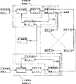
図1に本発明の実施例を示す。図の1は出力部、2は出力検出部、3は電極、4は制御部である。
出力部1は電気刺激信号を発生し、所定の強さに増幅して出力する。刺激信号は、図には記載していないが、操作部のキーなどにより入力されたデータを基に、又はソフトウェアで生成する。このパラメータは周波数と波形、刺激時間等である。出力の強さは、操作部の例えば出力設定キーで設定される。
出力部1の出力は、出力検出部2で検出され、この値は制御部4に送られ、出力検出部2で検出された出力と設定された出力値を制御部4で比較し、出力部1を制御し、設定された出力にして出力する。
FIG. 1 shows an embodiment of the present invention. In the figure, 1 is an output unit, 2 is an output detection unit, 3 is an electrode, and 4 is a control unit.
The output unit 1 generates an electrical stimulation signal, amplifies it to a predetermined strength, and outputs it. Although not shown in the figure, the stimulation signal is generated based on data input by a key of the operation unit or by software. These parameters are frequency and waveform, stimulation time, etc. The strength of output is set by, for example, an output setting key on the operation unit.
The output of the output unit 1 is detected by the output detection unit 2, and this value is sent to the
請求項1記載の本発明では、電気刺激信号の周波数や波形及び出力の強さをダイナミックに変化させて刺激をおこなうことを想定しているので、出力検出部2は、このような信号の変化があっても正確に出力を検出できるようにしている。このため、電気刺激信号の周波数が大きく変化しても、また、各出力の電気刺激信号の周波数や波形が異なっていても、正確に各出力を検出することができる。
本請求項記載の発明では、各出力出力部1の出力の強さを所定の値に設定して刺激を開始し、刺激開始時の各出力の強さの比を求めておき、刺激中に各出力部1の出力を検出し、制御部4で出力の刺激開始時の設定値と刺激時の測定値を比較し、刺激時の各出力部1の出力の比が刺激開始時の各出力部の出力の比になるように、制御部4で出力部1を制御する。
複数の出力を同時に通電するとき、各出力を調節して、各刺激のバランスをとっている。各出力は、電極3を介して、生体に供給され、刺激する。
In the present invention described in claim 1, since it is assumed that stimulation is performed by dynamically changing the frequency and waveform of the electrical stimulation signal and the intensity of the output, the output detection unit 2 is configured to change such a signal. Even if there is, it is possible to detect the output accurately. For this reason, each output can be accurately detected even if the frequency of the electrical stimulation signal changes greatly or the frequency or waveform of the electrical stimulation signal of each output is different.
In the invention described in this claim, the intensity of the output of each output output unit 1 is set to a predetermined value to start stimulation, the ratio of the intensity of each output at the start of stimulation is obtained, and during the stimulation The output of each output unit 1 is detected, and the
When energizing multiple outputs at the same time, each output is adjusted to balance each stimulus. Each output is supplied to the living body via the
周波数、波形、刺激の時間、変化のパターン等の刺激条件を設定し、刺激部位などを勘案して各出力部1の出力値を設定し、刺激を開始すると、所定の刺激条件で刺激をおこなう。例えば周波数を大きく変化させながら刺激をおこなう場合を考えると、所定の刺激条件(周波数、波形、刺激時間、治療時間など)にし、各出力の出力調節キーを上げていき、所定の強さにセットすると、各出力部1の出力は所定の割合(例えば出力1、2、3の出力を1:2:3のように)になり、刺激を開始する。
刺激中、刺激波形の変化に伴ってインピーダンスが変化し、出力も変化するが、出力は出力検出部2により正しく検出される。また、実際の刺激時の出力と刺激開始時に設定され出力が、各出力ごとに比較され、各出力部1の増幅率を変えて、常に、刺激開始時に設定された各出力の比を維持して出力される。前述の例では、出力1、2、3の出力が常に1:2:3のように維持される。この出力を時間的に変動させることもできる。
出力検出部2は,出力の波形や周波数等が変化しても,正確に出力を検出できるので、各出力の刺激波形が異なっていてもよい。
Set stimulation conditions such as frequency, waveform, stimulation time, change pattern, etc., set the output value of each output unit 1 taking into account the stimulation site, etc., and start stimulation, perform stimulation under the predetermined stimulation conditions . For example, considering the case where stimulation is performed while changing the frequency greatly, set to a predetermined strength by raising the output adjustment key for each output under predetermined stimulation conditions (frequency, waveform, stimulation time, treatment time, etc.) Then, the output of each output unit 1 becomes a predetermined ratio (for example, the output of
During stimulation, the impedance changes with the change of the stimulus waveform, and the output also changes, but the output is correctly detected by the output detection unit 2. Also, the output at the time of actual stimulation and the output set at the start of stimulation are compared for each output, and the ratio of each output set at the start of stimulation is always maintained by changing the amplification factor of each output unit 1. Is output. In the above example, the
Since the output detection unit 2 can accurately detect the output even if the output waveform, frequency, or the like changes, the stimulation waveform of each output may be different.
1:出力部
2:出力検出部
3:電極
4:制御部
1: Output unit 2: Output detection unit 3: Electrode 4: Control unit
Claims (1)
前記出力部(1)の出力を検出する出力検出部(2)と、
前記出力部(1)の出力を生体に供給する電極(3)と、
を有する出力系統を複数設けるとともに、
前記の各出力部(1)の出力を制御する制御部(4)を設け、
前記制御部(4)で前記出力部(1)を制御して前記電気刺激信号の周波数と波形及び出力の強さを変化させて電気刺激をおこないながら前記の各出力部(1)の出力を検出する電気刺激装置において、
治療開始時に、出力設定キーを操作して前記各出力部(1)の出力を適切な強さに設定して各検出部(2)で前記各出力部(1)の出力を検出し、
刺激中に、検出部(2)で前記各出力部(1)の出力を検出し、刺激中の前記各出力部(1)の出力の強さの比が、治療開始時に得た前記各出力部(1)の出力の強さの比と同じになるように、前記制御部(4)で前記の各出力部(1)を制御するようにしたことを特徴とする、バランス調節機能付き電気刺激装置。 An output unit (1) for generating and amplifying an electrical stimulation signal to a predetermined value;
An output detector (2) for detecting the output of the output unit (1);
An electrode (3) for supplying the output of the output unit (1) to a living body;
A plurality of output systems having
Provide a control unit (4) for controlling the output of each output unit (1),
The control unit (4) controls the output unit (1) to change the frequency and waveform of the electrical stimulation signal and the intensity of the output while performing electrical stimulation, and outputs each output unit (1). In the electrical stimulation device to detect,
At the start of treatment, operate the output setting key to set the output of each output unit (1) to an appropriate strength and detect the output of each output unit (1) with each detection unit (2) ,
During stimulation, the output of each output unit (1) is detected by the detection unit (2), and the output intensity ratio of each output unit (1) during stimulation is obtained at the start of treatment. The control unit (4) controls each of the output units (1) so that the output intensity ratio of the unit (1) is the same. Stimulator.
Priority Applications (1)
| Application Number | Priority Date | Filing Date | Title |
|---|---|---|---|
| JP2003410292A JP4480992B2 (en) | 2003-12-09 | 2003-12-09 | Electrical stimulator with balance adjustment function |
Applications Claiming Priority (1)
| Application Number | Priority Date | Filing Date | Title |
|---|---|---|---|
| JP2003410292A JP4480992B2 (en) | 2003-12-09 | 2003-12-09 | Electrical stimulator with balance adjustment function |
Publications (3)
| Publication Number | Publication Date |
|---|---|
| JP2005168642A JP2005168642A (en) | 2005-06-30 |
| JP2005168642A5 JP2005168642A5 (en) | 2007-02-15 |
| JP4480992B2 true JP4480992B2 (en) | 2010-06-16 |
Family
ID=34731417
Family Applications (1)
| Application Number | Title | Priority Date | Filing Date |
|---|---|---|---|
| JP2003410292A Expired - Lifetime JP4480992B2 (en) | 2003-12-09 | 2003-12-09 | Electrical stimulator with balance adjustment function |
Country Status (1)
| Country | Link |
|---|---|
| JP (1) | JP4480992B2 (en) |
Families Citing this family (2)
| Publication number | Priority date | Publication date | Assignee | Title |
|---|---|---|---|---|
| JP7087346B2 (en) | 2017-11-06 | 2022-06-21 | オムロンヘルスケア株式会社 | Electrotherapy device, control method, and treatment system |
| CN116808433A (en) * | 2023-06-09 | 2023-09-29 | 河南翔宇医疗设备股份有限公司 | Current regulating device, method, system, controller and therapeutic apparatus |
-
2003
- 2003-12-09 JP JP2003410292A patent/JP4480992B2/en not_active Expired - Lifetime
Also Published As
| Publication number | Publication date |
|---|---|
| JP2005168642A (en) | 2005-06-30 |
Similar Documents
| Publication | Publication Date | Title |
|---|---|---|
| McDermott et al. | Musical pitch perception with electrical stimulation of the cochlea | |
| Henry et al. | The relationship between speech perception and electrode discrimination in cochlear implantees | |
| US7231257B2 (en) | Cochlear implant sound processing method and system | |
| US7616999B2 (en) | System for generating a cochlear implant program using multi-electrode stimulation to elicit the electrically-evoked compound action potential | |
| US8600515B2 (en) | Encoding fine time structure in presence of substantial interaction across an electrode array | |
| NL1019206C2 (en) | Device and method for electromagnetic therapy. | |
| JP2008520376A5 (en) | ||
| US8527058B2 (en) | Methods and systems of automatically detecting an impedance of one or more electrodes in a cochlear implant system | |
| US20100161005A1 (en) | Optimizing stimulation therapy of an external stimulating device based on firing of action potential in target nerve | |
| EP2510875A3 (en) | Treatment apparatus for applying electrical impulses to the body of a patient | |
| US7117038B1 (en) | Method and system for obtaining stapedial reflexes in cochlear implant users using multiband stimuli | |
| US8412340B2 (en) | Tonality-based optimization of sound sensation for a cochlear implant patient | |
| US9770589B2 (en) | Electrical cochlear stimulation system and method | |
| US8233989B1 (en) | System and method for fitting a hearing prosthesis sound processor using alternative signals | |
| EP0204525B1 (en) | Low-frequency therapeutic device | |
| US20160151629A1 (en) | Cochlear implant system | |
| Vandali et al. | Pitch and loudness matching of unmodulated and modulated stimuli in cochlear implantees | |
| JP4480992B2 (en) | Electrical stimulator with balance adjustment function | |
| JP2005168642A5 (en) | ||
| KR100839673B1 (en) | High frequency stimulator of being adjustable for high frequency wave | |
| US20180280712A1 (en) | Magnetic Stimulation Device | |
| JP3019114U (en) | Interference low frequency treatment device with automatic current balance adjustment mechanism | |
| KR100615073B1 (en) | A low frequency and intermediate frequency electric treatment instrument | |
| JP4972859B2 (en) | Interference low frequency treatment device | |
| KR200379007Y1 (en) | A low frequency and intermediate frequency electric treatment instrument |
Legal Events
| Date | Code | Title | Description |
|---|---|---|---|
| A521 | Request for written amendment filed |
Free format text: JAPANESE INTERMEDIATE CODE: A523 Effective date: 20061208 |
|
| A621 | Written request for application examination |
Free format text: JAPANESE INTERMEDIATE CODE: A621 Effective date: 20061208 |
|
| A521 | Request for written amendment filed |
Free format text: JAPANESE INTERMEDIATE CODE: A523 Effective date: 20070118 |
|
| A131 | Notification of reasons for refusal |
Free format text: JAPANESE INTERMEDIATE CODE: A131 Effective date: 20090901 |
|
| A521 | Request for written amendment filed |
Free format text: JAPANESE INTERMEDIATE CODE: A523 Effective date: 20091030 |
|
| A131 | Notification of reasons for refusal |
Free format text: JAPANESE INTERMEDIATE CODE: A131 Effective date: 20091201 |
|
| A521 | Request for written amendment filed |
Free format text: JAPANESE INTERMEDIATE CODE: A523 Effective date: 20100128 |
|
| TRDD | Decision of grant or rejection written | ||
| A01 | Written decision to grant a patent or to grant a registration (utility model) |
Free format text: JAPANESE INTERMEDIATE CODE: A01 Effective date: 20100309 |
|
| A01 | Written decision to grant a patent or to grant a registration (utility model) |
Free format text: JAPANESE INTERMEDIATE CODE: A01 |
|
| A61 | First payment of annual fees (during grant procedure) |
Free format text: JAPANESE INTERMEDIATE CODE: A61 Effective date: 20100317 |
|
| FPAY | Renewal fee payment (event date is renewal date of database) |
Free format text: PAYMENT UNTIL: 20130326 Year of fee payment: 3 |
|
| R150 | Certificate of patent or registration of utility model |
Ref document number: 4480992 Country of ref document: JP Free format text: JAPANESE INTERMEDIATE CODE: R150 Free format text: JAPANESE INTERMEDIATE CODE: R150 |
|
| FPAY | Renewal fee payment (event date is renewal date of database) |
Free format text: PAYMENT UNTIL: 20130326 Year of fee payment: 3 |
|
| FPAY | Renewal fee payment (event date is renewal date of database) |
Free format text: PAYMENT UNTIL: 20140326 Year of fee payment: 4 |
|
| R250 | Receipt of annual fees |
Free format text: JAPANESE INTERMEDIATE CODE: R250 |
|
| R250 | Receipt of annual fees |
Free format text: JAPANESE INTERMEDIATE CODE: R250 |
|
| R250 | Receipt of annual fees |
Free format text: JAPANESE INTERMEDIATE CODE: R250 |
|
| R250 | Receipt of annual fees |
Free format text: JAPANESE INTERMEDIATE CODE: R250 |
|
| R250 | Receipt of annual fees |
Free format text: JAPANESE INTERMEDIATE CODE: R250 |
|
| R250 | Receipt of annual fees |
Free format text: JAPANESE INTERMEDIATE CODE: R250 |
|
| R250 | Receipt of annual fees |
Free format text: JAPANESE INTERMEDIATE CODE: R250 |
|
| R250 | Receipt of annual fees |
Free format text: JAPANESE INTERMEDIATE CODE: R250 |
|
| R250 | Receipt of annual fees |
Free format text: JAPANESE INTERMEDIATE CODE: R250 |
|
| R250 | Receipt of annual fees |
Free format text: JAPANESE INTERMEDIATE CODE: R250 |
|
| EXPY | Cancellation because of completion of term |