JP4480452B2 - Device fall prevention mechanism - Google Patents
Device fall prevention mechanism Download PDFInfo
- Publication number
- JP4480452B2 JP4480452B2 JP2004130923A JP2004130923A JP4480452B2 JP 4480452 B2 JP4480452 B2 JP 4480452B2 JP 2004130923 A JP2004130923 A JP 2004130923A JP 2004130923 A JP2004130923 A JP 2004130923A JP 4480452 B2 JP4480452 B2 JP 4480452B2
- Authority
- JP
- Japan
- Prior art keywords
- fall prevention
- prevention member
- spring
- lever
- locking
- Prior art date
- Legal status (The legal status is an assumption and is not a legal conclusion. Google has not performed a legal analysis and makes no representation as to the accuracy of the status listed.)
- Expired - Fee Related
Links
Images
Landscapes
- Accessory Devices And Overall Control Thereof (AREA)
- Electrophotography Configuration And Component (AREA)
- Casings For Electric Apparatus (AREA)
Description
本発明は、画像形成装置などの装置の転倒を防止する機構に関するものである。 The present invention relates to a mechanism for preventing a device such as an image forming apparatus from overturning.
画像形成装置などの事務機器、特に大型の機器には安全対策の一つとして転倒防止装置を取り付ける場合があり、かかる転倒防止装置としては種々のものがこれまでから提案されている。例えば特許文献1では、操作レバーを操作して支持脚を転倒防止位置に移動させる技術が提案されている。また特許文献2や特許文献3では、装置を所定位置に設置した後、装置内に収納されている転倒防止部材を転倒防止位置に引き出し、装置の転倒を防止する技術が提案されている。
しかし上記提案された技術では、装置を所定位置に設置した後、転倒防止部材を転倒防止位置に引き出すことを作業者が忘れることが起こり得る。このような場合、当然ながら装置の転倒は防止できない。一方、転倒防止部材を所定位置に引き出した場合、装置の転倒は防止できるものの、装置の下部から突出した転倒防止部材に使用者が足を引っかけるおそれがある。 However, in the proposed technique, the operator may forget to pull out the fall prevention member to the fall prevention position after the apparatus is installed at a predetermined position. In such a case, of course, it is impossible to prevent the apparatus from falling. On the other hand, when the fall-preventing member is pulled out to a predetermined position, the apparatus can be prevented from falling, but there is a possibility that the user may get caught in the fall-preventing member protruding from the lower part of the apparatus.
本発明はこのような従来の問題に鑑みてなされたものであり、装置を所定位置に設置した後に転倒防止部材を引き出すといった付加的作業を必要とせず、また使用者が足を引っかけるといった危険のまったくない、装置の転倒防止機構を提供することをその目的とするものである。 The present invention has been made in view of such a conventional problem, and does not require an additional work of pulling out the fall-preventing member after the apparatus is installed at a predetermined position, and there is a risk that the user may catch his / her foot. The object is to provide a mechanism for preventing the device from tipping over.
本発明によれば、装置底面に取り付けられ、装置底面と載置面との間に隙間を形成すると共に、バネで下方に付勢された装置支持部材と、装置から突出した位置と装置内に収納された位置とに出入可能に取り付けられた転倒防止部材と、前記転倒防止部材を収納された位置から突出した位置に移動させる付勢手段と、転倒防止部材を収納位置に係止する係止機構とを備え、前記装置支持部材が浮いた状態になると、前記係止機構が解除されて前記転倒防止部材が装置から突出し、装置の転倒を防ぐことを特徴とする装置の転倒防止機構が提供される。 According to the present invention, a device is attached to the bottom surface of the device and forms a gap between the bottom surface of the device and the mounting surface, and is biased downward by a spring, and a position protruding from the device and within the device. A fall-preventing member that is removably attached to the housed position, an urging means that moves the fall-preventing member to a position protruding from the housed position, and a latch that locks the fall-preventing member to the stowed position. Provided with a mechanism, and when the apparatus support member is in a floating state, the locking mechanism is released and the overturn prevention member protrudes from the apparatus to prevent the apparatus from overturning. Is done.
ここで前記係止機構として、中央部が軸支され、一方端が前記キャスタの上下移動によって上下移動する棒状のレバーと、中央部が軸支され、一方端が前記転倒防止部材と係合し、もう一方端が前記レバーの自由端と接触する係止部材と、係止部材を転倒防止部材と係合する方向に付勢するバネとを備えるものでもよい。 Here, as the locking mechanism, a central portion is pivotally supported, one end thereof is vertically moved by the vertical movement of the caster, a central portion is pivotally supported, and one end is engaged with the fall prevention member. The locking member may be provided with a locking member whose other end is in contact with the free end of the lever, and a spring that biases the locking member in a direction in which the locking member is engaged with the fall prevention member.
また安全性の一層向上させる観点からは、キャスタが浮いた状態になると警報音を発する警報装置をさらに備えるのがよい。 From the viewpoint of further improving safety, it is preferable to further include an alarm device that emits an alarm sound when the caster is in a floating state.
本発明の転倒防止機構では、通常状態では転倒防止部材は装置内に収納されているので、従来のような装置の使用者が転倒防止部材に足を引っかけるといった問題は発生しない。また、装置を所定位置に設置した後に転倒防止部材を引き出すといった付加的作業を必要としないので、作業者が転倒防止部材を引き出し忘れるという問題も発生しない。 In the fall prevention mechanism of the present invention, since the fall prevention member is housed in the apparatus in a normal state, there is no problem that the user of the apparatus of the prior art hooks the fall prevention member. Further, since an additional work of pulling out the fall prevention member after the apparatus is installed at a predetermined position is not required, the problem that the operator forgets to pull out the fall prevention member does not occur.
ここで第1の発明に係る転倒防止機構の係止機構として、中央部が軸支され、一方端が前記装置支持部材の上下移動によって上下移動する棒状のレバーと、中央部が軸支され、一方端が前記転倒防止部材と係合し、もう一方端が前記レバーの自由端と接触する係止部材と、係止部材を転倒防止部材と係合する方向に付勢するバネとを備えるものを用いると、機構の簡易化・軽量化などが図れる。 Here, as a locking mechanism of the fall prevention mechanism according to the first invention, a central portion is pivotally supported, and one end is vertically supported by the vertical movement of the device support member, and the central portion is pivotally supported, One end is engaged with the fall prevention member and the other end is in contact with the free end of the lever, and includes a spring that biases the latch member in a direction to engage the fall prevention member. Using can make the mechanism simpler and lighter.
また装置支持部材が浮いた状態になると警報音を発する警報装置をさらに設けると、安全性の一層向上が図れる。 Further, if an alarm device that emits an alarm sound when the device support member is in a floating state is further provided, safety can be further improved.
以下、本発明の転倒防止装置について図に基づいて説明する。なお、本発明はこれらの実施形態に何ら限定されるものではない。 Hereinafter, the fall prevention device of the present invention will be described with reference to the drawings. The present invention is not limited to these embodiments.
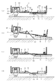
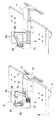
図1に、第1の発明に係る転倒防止装置の一実施形態を示す概略構成図を示す。図1の転倒防止装置では、装置100の底面に形成された凹部101にキャスタ(装置支持部材)1が取り付けられている。凹部101の上面とキャスタ1の間にはバネ2が介装され、このバネ2によってキャスタ1は下方へ常に付勢されている。キャスタ1の台座11の側面には突起12が形成され、この突起12が凹部101の側壁に形成された長孔102に遊挿され、キャスタ1はこの長孔102の範囲で上下方向に移動可能である。
In FIG. 1, the schematic block diagram which shows one Embodiment of the fall prevention apparatus which concerns on 1st invention is shown. In the overturn prevention device of FIG. 1, a caster (device support member) 1 is attached to a
次に係止機構5について説明する。棒状のレバー51と係止部材52とが揺動可能にそれぞれ軸511,521で支持され、レバー51の一方端はキャスタ1の台座11に接続し、もう一方端は係止部材52の一方端の下側に入り込む形で係止部材52と接触している。レバー51と接触する係合部材52の端部には、係合部材52を反時計回りに付勢するバネ53が取り付けられ、係止部材52のもう一方端側には爪部522が形成されている。転倒防止部材3に形成された係合孔31にこの爪部522が係合することによって、転倒防止部材3は収納位置に保持される。なお、キャスタ1は装置底面の四隅に通常取り付けられるので、レバー51と係合部材52、転倒防止部材3とを直線状に配設すると、対向するキャスタ1’(図2に図示)に当たる。そこで、図2及び図3に示すように、レバー51を「L」字状に曲げて、転倒防止部材3がキャスタ1’に当たらないようにするのが実用的である。もちろん、レバー51と係合部材52、転倒防止部材3とを直線状に配設し、対向するキャスタ1’の取り付け位置を移動させても構わない。
Next, the
図1に戻って、転倒防止部材3は装置の底面に移動可能に取り付けられている。具体的には、転倒防止部材3の上面から上方に延出した突片322が、装置100の底面に穿設された長孔104に遊挿され、装置100の底面に形成された突起105と、転倒防止部材3の突片32とがバネ(付勢手段)4によって接続されている。このバネ4により、転倒防止部材3は装置から外方へ突出するように常に付勢される。
Returning to FIG. 1, the
第1の発明に係る転倒防止装置の作動機構を図1に基づいて説明する。前述のように、通常状態では、係止部材52の爪部522が転倒防止部材3の係合孔31に係合し、転倒防止部材3は収納位置に保持されている(図1(a))。地震あるいは装置の一方側に大きな力が加わり装置100が傾くと、キャスタ1が載置面から離れる。すると、バネ2によって、キャスタ1の突起12が長孔102の下部に当接するまでキャスタ1は下方に移動する(同図(b))。このキャスタ1の下方への移動によって、レバー51は軸511を中心として反時計回りに回転し、バネ53に抗して係止部材52を時計回りに回転させる。係止部材52が時計回りの回転すると爪部522と係合孔31との係合が解除され、転倒防止部材3はバネ4によって装置の外方(図では右方)へ突出する。これにより、装置100の転倒が防止される。
An operation mechanism of the overturn prevention device according to the first invention will be described with reference to FIG. As described above, in the normal state, the
転倒を免れた装置は元の状態、すなわちキャスタ1が載置面に着いた状態に戻る。すると、装置重量によってキャスタ1はバネ2に抗して上方に移動する(同図(c))。このキャスタ1の上方への移動によって、レバー51は軸511を中心として時計回りに回転し、係止部材52はバネ53によって反時計回りに回転し、爪部522は係合孔31との係合位置となる。一方、転倒防止部材3は突出した状態のままである。装置100が転倒するおそれがなくなった場合は、転倒防止部材3を手動によって装置内に押し入れる。すると、係止部材52の爪部522が転倒防止部材3の係合孔31に入って係合し、転倒防止部材3は収納位置に保持される(同図(d))。
The device which has been prevented from falling is returned to the original state, that is, the state in which the
以上説明した実施形態では、装置支持部材としてキャスタを用いたがこれに限定されるものではなく、例えばいわゆる台ゴムなどであっても構わない。また、係止機構としてレバーの端部に爪部を設け、この爪部が転倒防止部材の係止孔と係合するようにして、係止部材をなくしても構わない。 In the embodiment described above, a caster is used as the apparatus support member, but the present invention is not limited to this. For example, a so-called base rubber may be used. Further, as a locking mechanism, a claw portion may be provided at the end of the lever, and the claw portion may be engaged with a locking hole of the fall prevention member so that the locking member is eliminated.
また装置に警報装置を設け、キャスタが浮いた場合には警報装置から警報音を発するようにしてもよい。そしてまた、装置底面の四隅にキャスタが設けられている場合に、2つのキャスタが浮いた状態になったことが検知されると、その2つのキャスタが取り付けられた辺と対向する辺の方向に装置が倒れる危険があると、倒れる方向をも含めて報知するようにしてもよい。 Further, an alarm device may be provided in the device, and an alarm sound may be emitted from the alarm device when the caster floats. In addition, when casters are provided at the four corners of the bottom surface of the apparatus, if it is detected that the two casters are in a floating state, the casters are arranged in the direction of the side opposite to the side on which the two casters are attached. If there is a risk of the device falling, it may be notified including the direction in which the device falls.
次に、第2の発明に係る転倒防止機構について説明する。この発明に係る転倒防止機構の、前記発明と異なるところは、装置の傾きを装置支持部材が浮いたかどうかではなく、検知手段で検知することにある。これにより、装置のわずかな傾きであっても検知でき、装置の転倒防止を早い時期に防ぐことができる。 Next, a fall prevention mechanism according to the second invention will be described. The fall prevention mechanism according to the present invention is different from the above invention in that the inclination of the apparatus is detected not by whether the apparatus support member is lifted, but by the detection means. As a result, even a slight inclination of the apparatus can be detected, and prevention of the apparatus from falling can be prevented at an early stage.
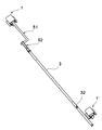
この発明で使用する検知手段としては例えば図4に示すものが挙げられる。同図(a)の検知手段6は、装置の一方向の傾きを検知するものであって、常に鉛直方向を向くように軸63によって上部が装置に支持された遮光板61と、上側が開口した「コ」字状のセンサ62とを備える。装置が載置面に載置されている状態では、遮光板61の下部がセンサ62の発光部621と受光部622との間に位置し、発光部621からの光は遮光板61によって遮られ、受光部622では検知されない(図の左側図)。一方、装置に外力が働き装置が傾くと、装置に取り付けられたセンサ62は装置と共に傾くが、遮光板61は鉛直方向を向いたままとなるため、発光部621からの光が遮光板61に遮られることなく受光部622に届くようになる(図の右側図)。これにより、装置の傾きが検知される。
Examples of the detection means used in the present invention include those shown in FIG. The detecting means 6 in FIG. 6A detects the inclination in one direction of the apparatus, and the upper part is supported by the apparatus by a shaft 63 so as to always face the vertical direction, and the upper side is opened. And a “U” -shaped sensor 62. In a state where the apparatus is mounted on the mounting surface, the lower part of the light shielding plate 61 is located between the light emitting unit 621 and the
図4(a)の検知手段6では装置の一方向の傾きしか検知できないので、装置の複数方向の傾きを検知する場合には、複数個の検知手段を設ける必要がある。そこで同図(b)の検知手段6’では、一つの検知手段で装置のあらゆる方向の傾きを検知できるようにした。図4(b)の検知手段6’は、紐部材66で装置に吊り下げられた導電性棒64と、この導電性棒64の下部が遊挿される孔651を備えた導電性リング65とを有する。導電性棒64および導電性リング65には電圧が印加されており、両者が接触することによって電流が流れる。つまりスイッチの作用を奏する。装置が載置面に載置されている状態では、導電性棒64は鉛直方向を向き、導電性リング65の孔651の略中央に位置し、導電性リング65とは非接触状態である。一方、装置が外力が働き装置が傾くと、装置に取り付けられた導電性リング65は装置と共に傾くが、導電性棒64は鉛直方向を向いたままとなるため、導電性棒64と導電性リング65が接触し電流が流れる。これにより装置の傾きが検知される。
Since the detection means 6 of FIG. 4A can detect only the inclination of the apparatus in one direction, it is necessary to provide a plurality of detection means when detecting the inclination of the apparatus in a plurality of directions. In view of this, the detecting means 6 'shown in FIG. 6 (b) can detect the inclination of the apparatus in any direction with a single detecting means. 4B includes a
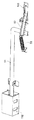
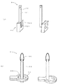
次に、転倒防止部材の具体的動きについて説明する。図5に、転倒防止機構の一例を示す斜視図を示す。図5の機構では、底面にキャスタ1”が取り付けられた台座Bの上面に、ソレノイド91と、ソレノイド91のオン・オフによって進退するロッド92と、一方端がロッド92にピン止めされ、軸95により揺動可能に支持されたL字状のレバー94と、規制板75で位置決めされた状態で突出位置と収納位置とに出入可能に取り付けられた転倒防止部材7と、転倒防止部材7を装置外方へ突出させるバネ(付勢手段)8が配設されている。転倒防止部材7は、水平に伸びた基部71と、基部71の先端から垂下した下降部72と、下降部72の先端に中央部分が接続した接地部73とを有し、基部71の後部には係合穴74が形成されている。
Next, the specific movement of the fall prevention member will be described. FIG. 5 is a perspective view showing an example of the fall prevention mechanism. In the mechanism of FIG. 5, a
通常状態では、外嵌されたバネ93によってロッド92はソレノイド91から進出した位置にあり、これによりレバー94の先端は転倒防止部材7の係合穴74と係合し、転倒防止部材7は収納位置に係止されている。一方、前記説明した検知部材により装置の傾きが検知されると、ソレノイド91がオンとなりロッド92が後退した位置となる。すると、レバー94が軸95を中心に反時計回りに回転し、レバー94の先端と転倒防止部材7の係合穴74との係合状態が解除され、転倒防止部材7はバネ8によって装置外方へ突出する。これにより装置の転倒が防止される。
In the normal state, the
その後、転倒を免れた装置が元の状態に戻ったことが検知手段によって検知されると、ソレノイド91がオフとなり、ロッド92がバネ93により進出した位置となる。すると、レバー94が軸95を中心として時計回りに回転し、レバー94の先端が転倒防止部材7の係合穴74と係合する位置となる。このとき、転倒防止部材7は装置から突出した状態のままであるので、手動によってバネ8に抗して転倒防止部材7を装置内に押し入れ、レバー94の先端と係合穴74とを係合させて転倒防止部材7を収納位置に係止する。
Thereafter, when the detection means detects that the device that has been prevented from overturning has returned to its original state, the
この発明に係る転倒防止機構は装置下部外周のどの位置に設けてもよい。装置のすべての方向への転倒を防止するには、平面視の形状が四角形の装置であれば4辺の中央部にそれぞれ転倒防止機構を設けるのが好ましい。転倒防止部材の装置からの突出量や形状は、装置の大きさや形状などから適宜決定すればよい。 The fall prevention mechanism according to the present invention may be provided at any position on the outer periphery of the lower part of the apparatus. In order to prevent the device from falling in all directions, it is preferable to provide a fall prevention mechanism at the center of each of the four sides if the shape of the plan view is a square device. The amount and shape of protrusion of the fall prevention member from the device may be determined as appropriate from the size and shape of the device.
1 キャスタ(装置支持部材)
2 バネ
3 転倒防止部材
4 バネ(付勢手段)
5 係止機構
6,6’ 検知手段
7 転倒防止部材
8 バネ(付勢手段)
9 係止機構
51 レバー
52 係止部材
53 バネ
61 遮光板
62 センサ
63 軸
64 導電性棒
65 導電性リング
66 紐部材
71 基部
72 下降部
73 接地部
74 係合穴
91 ソレノイド
92 ロッド
93 バネ
94 レバー
621 発光部
622 受光部
651 孔
1 Casters (device support members)
2
5
DESCRIPTION OF SYMBOLS 9
Claims (3)
Priority Applications (1)
| Application Number | Priority Date | Filing Date | Title |
|---|---|---|---|
| JP2004130923A JP4480452B2 (en) | 2004-04-27 | 2004-04-27 | Device fall prevention mechanism |
Applications Claiming Priority (1)
| Application Number | Priority Date | Filing Date | Title |
|---|---|---|---|
| JP2004130923A JP4480452B2 (en) | 2004-04-27 | 2004-04-27 | Device fall prevention mechanism |
Publications (2)
| Publication Number | Publication Date |
|---|---|
| JP2005313341A JP2005313341A (en) | 2005-11-10 |
| JP4480452B2 true JP4480452B2 (en) | 2010-06-16 |
Family
ID=35441278
Family Applications (1)
| Application Number | Title | Priority Date | Filing Date |
|---|---|---|---|
| JP2004130923A Expired - Fee Related JP4480452B2 (en) | 2004-04-27 | 2004-04-27 | Device fall prevention mechanism |
Country Status (1)
| Country | Link |
|---|---|
| JP (1) | JP4480452B2 (en) |
Families Citing this family (3)
| Publication number | Priority date | Publication date | Assignee | Title |
|---|---|---|---|---|
| JP2007334259A (en) * | 2006-06-19 | 2007-12-27 | Sharp Corp | Display device |
| CN108340690A (en) * | 2018-02-07 | 2018-07-31 | 嘉兴市汉鼎五金制造有限公司 | A kind of spray drawing machine bracket with stabilization function |
| CN116608901B (en) * | 2023-05-19 | 2024-05-03 | 武汉宏联电线电缆有限公司 | Power equipment monitor |
Family Cites Families (2)
| Publication number | Priority date | Publication date | Assignee | Title |
|---|---|---|---|---|
| JPH0219995U (en) * | 1988-07-18 | 1990-02-09 | ||
| JP2004045793A (en) * | 2002-07-12 | 2004-02-12 | Ricoh Co Ltd | office supply |
-
2004
- 2004-04-27 JP JP2004130923A patent/JP4480452B2/en not_active Expired - Fee Related
Also Published As
| Publication number | Publication date |
|---|---|
| JP2005313341A (en) | 2005-11-10 |
Similar Documents
| Publication | Publication Date | Title |
|---|---|---|
| JP2006127522A (en) | Docking station | |
| JP2006009560A (en) | Safety lever operating structure in hood latch assembly | |
| US8851236B2 (en) | Safety lockout system | |
| JP4480452B2 (en) | Device fall prevention mechanism | |
| JP6662345B2 (en) | Elevator pit ladder device | |
| JP4587201B2 (en) | Handle equipment for equipment transportation, equipment, image forming equipment | |
| JP6120396B2 (en) | Rotating rail lock structure & bed | |
| JP2015141385A (en) | Fall prevention device and image forming apparatus including the same | |
| JP2005227633A (en) | Safety device against overturning of equipment | |
| JP2005053668A (en) | Pallet lock device for forklift | |
| JP3797271B2 (en) | Manhole retractable trap | |
| JP2005278895A (en) | Fall prevention device and soccer goal with the same | |
| JP2021186456A (en) | Furniture with overturn prevention function | |
| JP3981890B1 (en) | Bed | |
| JP4212589B2 (en) | Vehicle equipped with a receiving platform lifting device | |
| KR200280755Y1 (en) | Trailer with a built-in footboard | |
| JP4153869B2 (en) | Caster turning control structure | |
| JP2008142218A (en) | Stored bed | |
| JP2009042413A (en) | Image forming apparatus | |
| TW523484B (en) | Automatically locking and releasing connecting assembly | |
| JPH10338366A (en) | High volume feeder | |
| JP2008191556A (en) | Elevation mechanism for projector and projector | |
| JP2008267588A (en) | Control mechanism of seismic isolator | |
| JPH0629369Y2 (en) | Step board device for lifting floor | |
| JP6074084B1 (en) | Earthquake breaker breaker |
Legal Events
| Date | Code | Title | Description |
|---|---|---|---|
| A621 | Written request for application examination |
Free format text: JAPANESE INTERMEDIATE CODE: A621 Effective date: 20070327 |
|
| A131 | Notification of reasons for refusal |
Free format text: JAPANESE INTERMEDIATE CODE: A131 Effective date: 20091222 |
|
| A521 | Request for written amendment filed |
Free format text: JAPANESE INTERMEDIATE CODE: A523 Effective date: 20100216 |
|
| TRDD | Decision of grant or rejection written | ||
| A01 | Written decision to grant a patent or to grant a registration (utility model) |
Free format text: JAPANESE INTERMEDIATE CODE: A01 Effective date: 20100316 |
|
| A01 | Written decision to grant a patent or to grant a registration (utility model) |
Free format text: JAPANESE INTERMEDIATE CODE: A01 |
|
| A61 | First payment of annual fees (during grant procedure) |
Free format text: JAPANESE INTERMEDIATE CODE: A61 Effective date: 20100316 |
|
| FPAY | Renewal fee payment (event date is renewal date of database) |
Free format text: PAYMENT UNTIL: 20130326 Year of fee payment: 3 |
|
| R150 | Certificate of patent or registration of utility model |
Free format text: JAPANESE INTERMEDIATE CODE: R150 |
|
| FPAY | Renewal fee payment (event date is renewal date of database) |
Free format text: PAYMENT UNTIL: 20130326 Year of fee payment: 3 |
|
| S533 | Written request for registration of change of name |
Free format text: JAPANESE INTERMEDIATE CODE: R313533 |
|
| FPAY | Renewal fee payment (event date is renewal date of database) |
Free format text: PAYMENT UNTIL: 20130326 Year of fee payment: 3 |
|
| R350 | Written notification of registration of transfer |
Free format text: JAPANESE INTERMEDIATE CODE: R350 |
|
| FPAY | Renewal fee payment (event date is renewal date of database) |
Free format text: PAYMENT UNTIL: 20130326 Year of fee payment: 3 |
|
| LAPS | Cancellation because of no payment of annual fees |