JP4480244B2 - Bolt flange assembly for supplying cooling air - Google Patents
Bolt flange assembly for supplying cooling air Download PDFInfo
- Publication number
- JP4480244B2 JP4480244B2 JP2000269441A JP2000269441A JP4480244B2 JP 4480244 B2 JP4480244 B2 JP 4480244B2 JP 2000269441 A JP2000269441 A JP 2000269441A JP 2000269441 A JP2000269441 A JP 2000269441A JP 4480244 B2 JP4480244 B2 JP 4480244B2
- Authority
- JP
- Japan
- Prior art keywords
- annular
- assembly
- flanges
- bolt holes
- ring
- Prior art date
- Legal status (The legal status is an assumption and is not a legal conclusion. Google has not performed a legal analysis and makes no representation as to the accuracy of the status listed.)
- Expired - Fee Related
Links
Images


Classifications
-
- F—MECHANICAL ENGINEERING; LIGHTING; HEATING; WEAPONS; BLASTING
- F01—MACHINES OR ENGINES IN GENERAL; ENGINE PLANTS IN GENERAL; STEAM ENGINES
- F01D—NON-POSITIVE DISPLACEMENT MACHINES OR ENGINES, e.g. STEAM TURBINES
- F01D5/00—Blades; Blade-carrying members; Heating, heat-insulating, cooling or antivibration means on the blades or the members
- F01D5/02—Blade-carrying members, e.g. rotors
- F01D5/06—Rotors for more than one axial stage, e.g. of drum or multiple disc type; Details thereof, e.g. shafts, shaft connections
- F01D5/066—Connecting means for joining rotor-discs or rotor-elements together, e.g. by a central bolt, by clamps
-
- F—MECHANICAL ENGINEERING; LIGHTING; HEATING; WEAPONS; BLASTING
- F01—MACHINES OR ENGINES IN GENERAL; ENGINE PLANTS IN GENERAL; STEAM ENGINES
- F01D—NON-POSITIVE DISPLACEMENT MACHINES OR ENGINES, e.g. STEAM TURBINES
- F01D5/00—Blades; Blade-carrying members; Heating, heat-insulating, cooling or antivibration means on the blades or the members
- F01D5/02—Blade-carrying members, e.g. rotors
- F01D5/08—Heating, heat-insulating or cooling means
- F01D5/081—Cooling fluid being directed on the side of the rotor disc or at the roots of the blades
- F01D5/082—Cooling fluid being directed on the side of the rotor disc or at the roots of the blades on the side of the rotor disc
-
- F—MECHANICAL ENGINEERING; LIGHTING; HEATING; WEAPONS; BLASTING
- F01—MACHINES OR ENGINES IN GENERAL; ENGINE PLANTS IN GENERAL; STEAM ENGINES
- F01D—NON-POSITIVE DISPLACEMENT MACHINES OR ENGINES, e.g. STEAM TURBINES
- F01D5/00—Blades; Blade-carrying members; Heating, heat-insulating, cooling or antivibration means on the blades or the members
- F01D5/02—Blade-carrying members, e.g. rotors
- F01D5/08—Heating, heat-insulating or cooling means
- F01D5/085—Heating, heat-insulating or cooling means cooling fluid circulating inside the rotor
- F01D5/088—Heating, heat-insulating or cooling means cooling fluid circulating inside the rotor in a closed cavity
-
- Y—GENERAL TAGGING OF NEW TECHNOLOGICAL DEVELOPMENTS; GENERAL TAGGING OF CROSS-SECTIONAL TECHNOLOGIES SPANNING OVER SEVERAL SECTIONS OF THE IPC; TECHNICAL SUBJECTS COVERED BY FORMER USPC CROSS-REFERENCE ART COLLECTIONS [XRACs] AND DIGESTS
- Y02—TECHNOLOGIES OR APPLICATIONS FOR MITIGATION OR ADAPTATION AGAINST CLIMATE CHANGE
- Y02T—CLIMATE CHANGE MITIGATION TECHNOLOGIES RELATED TO TRANSPORTATION
- Y02T50/00—Aeronautics or air transport
- Y02T50/60—Efficient propulsion technologies, e.g. for aircraft
Landscapes
- Engineering & Computer Science (AREA)
- Mechanical Engineering (AREA)
- General Engineering & Computer Science (AREA)
- Turbine Rotor Nozzle Sealing (AREA)
Description
【0001】
【技術分野】
この発明は、航空機のガスタービンエンジン・タービンロータ及びディスクに関し、特に隣り合うタービンロータディスクのフランジのボルト止め構造に関する。
【0002】
【背景技術】
ガスタービンエンジンには多段タービンロータを用いるものが多く、隣り合うタービンディスクを互いにボルト止めしてタービンロータを形成している。高圧タービンロータでは、冷却空気をタービンディスクのリムを通してタービンブレードの根元に供給しなければならない。隣り合うディスクは、端部にフランジを設けた円錐形アームを有し、普通フランジを互いにボルト締結して円錐形壁アセンブリを形成し、冷却空気がリム及びタービンブレード根元に達するには、この円錐形壁アセンブリを乗り越えなければならない。
【0003】
通常、ディスクのアームに穴(ホール)を設け、冷却空気がアームを横切って流れるようにしている。ディスクのアームに穴を設けるとディスクの強度を弱め、寿命を制限するので、ディスクのアームに貫通する穴をなくすのが望ましい。
【0004】
【発明の概要】
この発明の好適な実施例によるガスタービンエンジン・ロータアセンブリは、軸線のまわりに円周方向に配置され、軸線方向に離間された前部及び後部ディスクを有する。前部ディスクは後方に延在する環状前部アームを有し、後部ディスクは前方に延在する環状後部アームを有する。前部及び後部アームの前端及び後端に前部及び後部フランジがそれぞれ設けられる。一連の互いに心合わせされた前部及び後部ボルト穴が前部及び後部フランジに軸線方向に貫通する。スカロップ型環状リングが複数の円周方向に離間されたタブ及びタブ間の空所を有し、前部及び後部フランジ間に配置されている。複数の円周方向に離間されたタブに複数のリングボルト穴が軸線方向に貫通し、ここでリングボルト穴、前部ボルト穴及び後部ボルト穴の対応するものが軸線方向に心合わせされている。一連の前部及び後部アパーチャが前部及び後部フランジに軸線方向に貫通し、前記空所が前部及び後部アパーチャの対応するものと流体連通している。一連のアパーチャのそれぞれが円周方向に、前部及び後部ボルト穴のうち2つの間に配置されているのが好ましい。複数のボルトを用いて前部及び後部フランジを互いに装着するのが好ましく、各ボルトがリングボルト穴、前部ボルト穴及び後部ボルト穴の対応するものに貫通配置されている。前部及び後部ボルト穴の少なくとも一方がアパーチャと異なり、ボルトをアパーチャに挿入できないようにする。
【0005】
本発明の具体的な実施例によるガスタービンエンジン・タービンロータアセンブリは、前部及び後部ディスク間に延在する環状段間シールを含む。前部及び後部ディスクは、その前部及び後部環状外側リムが、前部及び後部環状ウェブにより前部及び後部環状ボアに連結された構成である。環状前部アームは前部ウェブから後方に延在し、環状後部アームは後部ウェブから前方に延在する。前部及び後部フランジが前部及び後部アームの前端及び後端で互いに着脱自在に取り付けられ、かくして前部及び後部フランジと段間シールとの間に半径方向に延在する半径方向外方環状段間空間を画定するとともに、前部及び後部フランジより半径方向内方に延在する半径方向内方環状段間空間を画定する。本発明はさらに、冷却空気を前部及び後部フランジ間に内方環状段間空間から外方環状段間空間に流す手段を備える。複数の冷却可能なタービンブレードが後部リムの外周のまわりに装着される。各ブレードは後部リムに装着された根元と、この根元に取り付けられたプラットホームから半径方向外方に延在する冷却可能なエアーホイルとを有する。冷却通路を用いて冷却空気を外方環状段間空間から冷却可能なエアーホイルに流す。冷却通路は、外方環状段間空間から冷却可能なブレードの根元及びエアーホイルまでつながる、後部リムに形成された冷却空気通路を含む。
【0006】
【好適な実施態様】
本発明を特徴付けると考えられる新規な構成要素は特許請求の範囲に記載したとおりである。本発明の構成、目的及び効果を、添付の図面を参照しながら以下に詳述する。
【0007】
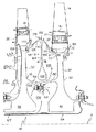
図1に、本発明の実施例として、ガスタービンエンジンの軸線Aのまわりに円周方向に配置された高圧タービンロータアセンブリ10を示す。第1段又は前部ディスク16は、その外周まわりに円周方向に離間された複数の第1段ブレード18を有し、第2段又は後部ディスク20は、その外周まわりに円周方向に離間された複数の第2段ブレード22を有する。前部及び後部ディスク16及び20はそれぞれ、環状外側前部及び後部ディスクリム26及び28が、環状前部及び後部ディスクウェブ30及び34により環状前部及び後部ディスクボア38及び42に取り付けられた構成である。
【0008】
第1段及び第2段ブレード18及び22はそれぞれ、根元12及びエアーホイル14を有し、プラットホーム15が両者間に配置されこれらと一体になっている。根元12は後部ディスクリム28の相補形状のスロット17内に配置され、スロット17は後部ディスク20の前面33から後面39まで後部リムを軸線方向に貫通する。スロット17はディスク前面33上の前部環状スペース31に開口している。冷却空気を前部環状スペース31からスロット17に通し、ついで根元12の冷却通路を経てエアーホイル14内の冷却回路に供給し、エアーホイルを冷却するのに使用する。
【0009】
前部及び後部ディスク16及び20はエンジンシャフト(図示せず)に連結されている。この連結には、通常、スプラインアセンブリ(図示せず)を使用して前部及び後部ディスク16及び20をエンジンシャフトに取り付ける。前部及び後部ディスク16及び20は、フランジ付きの前部及び後部環状アーム58及び60を含む。
【0010】
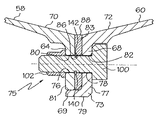
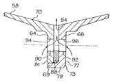
図2、図3及び図4に、前部及び後部アーム58及び60及びその前端70及び後端72に配置され、一体に形成された前部及び後部フランジ64及び68を詳細に示す。ラベットジョイント(さねはぎ)69を用いて前部及び後部フランジ64及び68を連結する。ラベットジョイント69は、後部フランジ68の第1半径方向内端77にラベット73を含み、軸線方向に延在する環状レッグ79を有し、この環状レッグ79が前部フランジ64の第2半径方向内端81と半径方向に接触している。前部及び後部フランジ64及び68は互いにボルトその他の手段で、好ましくは75で総称するボルト止めアセンブリを用いて、着脱自在に連結される。
【0011】
ボルト止めアセンブリ75では、一連(76,78)の心合わせされた前部及び後部ボルト穴80及び82がそれぞれ前部及び後部フランジ64及び68に軸線方向に貫通している。また、一連(90,92)の、好ましくは軸線方向に心合わせされた前部及び後部アパーチャ94及び96がそれぞれ前部及び後部フランジ64及び68に貫通している。前部及び後部アパーチャ94及び96が前部及び後部ボルト穴80及び82と円周方向に整列され、ボルト穴80及び82間で等間隔に配置されているのが好ましい。図面では、前部及び後部アパーチャ94及び96はそれぞれ、前部及び後部ボルト穴80及び82のうち円周方向に隣接する2つのボルト穴間に配置されている。前部及び後部アパーチャ94及び96は、前部及び後部フランジ64及び68におけるフープ応力を緩和あるいは軽減するのに用いられる。前部及び後部アパーチャ94及び96は、前部及び後部環状アーム58及び60のボルト止めアセンブリを通して冷却空気を送るのにも用いられる。複数の円周方向に離間されたタブ83を有し、タブ間に空所84が介在するスカロップ型環状リング88が、前部及び後部フランジ64及び68間に配置されている。複数の円周方向に離間されたタブ83それぞれに複数のリングボルト穴86が軸線方向に貫通し、ここでリングボルト穴86、前部ボルト穴80及び後部ボルト穴82の対応するものが軸線方向に心合わせされている。空所84は前部及び後部アパーチャ94及び96の対応するものと流体連通している。
【0012】
複数のボルト100が、リングボルト穴86、前部ボルト穴80及び後部ボルト穴82の対応するものに貫通配置されている。ボルト100はナット102で所定位置に固定される。前部及び後部ボルト穴80及び82は前部及び後部アパーチャ94及び96とは形状及び/又は寸法が異なるので、ボルト100をボルト穴ではなくアパーチャに誤って挿入することはない。C形クリップ140がボルト100のまわりのリング溝142にぴったりはまり、前部及び後部ディスク16及び20及び前部及び後部フランジ64及び68の組み立て又ははめ合わせ時に、スカロップ型環状リング88を所定位置に保持する。クリップ140は、前部及び後部フランジ64及び68をはめ合わせる際に、前部ボルト穴80のまわりの前部フランジ64の軸線方向に面する表面に設けた環状凹所144に収容されている。ボルト100は、平坦部105を有するD形ヘッド104を有し、平坦部105が後部アーム60に係合して、ナット102をボルトに締め付ける際にボルトが回転するのを防止する。
【0013】
スカロップ型環状リング88は、このリング自体に半径方向に向いた通路を有し、フランジに軸線方向に面する平滑面を用いるのを可能にする。このことは、アセンブリの強度に有効な作用をなし、フランジ及びディスクアームを小さくし、エンジン重量を小さくする設計を可能にする。また、フランジに半径方向通路を設けた場合に起こる可能性のあるこすれによる摩耗を軽減することにより、アセンブリの部材の寿命が長くなる。凹所は、前部フランジ及びスカロップ型環状リング88の軸線方向に面する平滑表面が最大接触面積にて当接するのに有効で、これにより強固なボルト止めアセンブリを実現する。
【0014】
図1に戻ると、環状段間シール118は、前部及び後部ディスク16及び20間に延在し、環状外側シェル120を含み、そこからシールウェブ124及びシールボア126が半径方向内方に垂下している。シェル120は、シール歯134を支持する円筒形中間部分132と、前部及び後部ディスク16及び20にそれぞれ連結された前部及び後部シールアーム128及び130とを含む。シェル120の前部及び後部シールアーム128及び130はそれぞれ、半径方向に延在するブレード保持リム136を有する。差し込み連結部138で前部シールアーム128を前部ディスク16に連結し、リング連結部139で後部シールアーム130を後部ディスク20に連結する。環状段間シール118が画定する半径方向外方の環状段間空間108は、半径方向には環状前部及び後部アーム58及び60のボルト止めアセンブリと段間シール118との間に延在し、軸線方向には前部及び後部ディスク16及び20間に延在する。
【0015】
冷却空気を、ガスタービンエンジンの圧縮機段から、前部ディスクボア38と環状冷却空気配管54シャフトとの間の環状通路107を通して、半径方向内方環状段間空間106(前部及び後部ディスク16及び20間に軸線方向に延在し、前部及び後部環状アーム58及び60のボルト止めアセンブリの半径方向内方に位置する)に供給する。つぎに、冷却空気を、ボルト止めアセンブリ75、前部及び後部アパーチャ94及び96、ついで空所84を経て、前部及び後部環状アーム58及び60間のボルト止めアセンブリより半径方向外方の環状段間空間108に流量調整しながら通す。冷却空気は、外方環状段間空間108からディスク前面33の前部環状スペース31を通過し、ついで前述したように、スロット17を経て根元12に流れる。冷却空気は根元12の空気通路を経てエアーホイル14の内部に流れる。圧縮機からタービン段への冷却空気の供給は当業界で周知である。
【0016】
図5に、図2〜4に示した単一部材のスカロップ型環状リング88に代わる、セグメント化されたスカロップ型環状リング188を示す。セグメント化されたスカロップ型環状リング188は、基本的には単一スカロップ型環状リング88と同じ方法で使用し、装填する。リングを2個、3個、4個又はそれ以上のセグメント190に分割することができ、各セグメントに同じ数のタブ83及び空所84を設ける必要はない。セグメント化されたスカロップ型環状リング188は、単一スカロップ型環状リング88を破砕、破壊するおそれのあるフープ応力を回避する。
【0017】
以上、本発明を好適な実施例と考えられるものについて説明したが、以上の教示内容から当業者には本発明の他の変更が明らかである。本発明は、このような変更例のすべてをその要旨の範囲内に含まれるものとして包含する。
【0018】
したがって、米国特許証にて保護されるべき対象は特許請求の範囲に記載、差別化した通りの発明である。
【図面の簡単な説明】
【図1】ガスタービンエンジンの2段高圧タービンロータ区分及び本発明の冷却通路内蔵ボルト止めアセンブリの線図的断面図である。
【図2】図1のボルト止めアセンブリの分解斜視図である。
【図3】図2の3−3線方向に見たボルト止めアセンブリのボルト穴を貫通する断面図である。
【図4】図2の4−4線方向に見たボルト止めアセンブリのボルト穴を貫通する断面図である。
【図5】図1のボルト止めアセンブリに用いる別のセグメント化されたスカロップ型環状リングの正面図である。
【符号の説明】
10 タービンロータアセンブリ
12 根元
14 エアーホイル
15 プラットホーム
16 第1段又は前部ディスク
17 スロット
18 第1段ブレード
20 第2段又は後部ディスク
22 第2段ブレード
26 前部ディスクリム
28 後部ディスクリム
30 前部ディスクウェブ
31 前部環状スペース
33 ディスク前面
34 後部ディスクウェブ
35 冷却空気通路
38 前部ディスクボア
39 ディスク裏面
42 後部ディスクボア
54 環状支持部材
58 前部アーム
60 後部アーム
64 前部フランジ
68 後部フランジ
69 ラベットジョイント
70 前端
72 後端
73 ラベット
75 ボルト止めアセンブリ
76 前一連
77 内端
78 後一連
79 環状レッグ
80 前部ボルト穴
81 内端
82 後部ボルト穴
83 タブ
84 空所
86 リングボルト穴
88 環状リング
90 前一連
92 後一連
94 前アパーチャ
96 後アパーチャ
100 ボルト
102 ナット
104 D形ヘッド
105 平坦部
106 内方環状段間空間
107 環状通路
108 外方環状段間空間
118 段間シール
120 外側シェル
124 シールウェブ
126 シールボア
128 前部シールアーム
130 後部シールアーム
132 中間部分
134 シール歯
136 保持リム
138 差込連結部
140 クリップ
142 リング溝
144 凹所
188 セグメント化スカロップ型環状リング
190 セグメント
A 軸線[0001]
【Technical field】
The present invention relates to an aircraft gas turbine engine / turbine rotor and disk, and more particularly, to a bolted structure of a flange of an adjacent turbine rotor disk.
[0002]
[Background]
Many gas turbine engines use a multistage turbine rotor, and adjacent turbine disks are bolted together to form a turbine rotor. In high pressure turbine rotors, cooling air must be supplied to the roots of the turbine blades through the rim of the turbine disk. Adjacent discs have conical arms with flanges at the ends, and the normal flanges are bolted together to form a conical wall assembly that allows the cooling air to reach the rim and turbine blade roots. You must overcome the shaped wall assembly.
[0003]
Usually, a hole (hole) is provided in the arm of the disk so that the cooling air flows across the arm. Providing a hole in the disk arm reduces the strength of the disk and limits its life, so it is desirable to eliminate the hole penetrating the disk arm.
[0004]
SUMMARY OF THE INVENTION
A gas turbine engine and rotor assembly according to a preferred embodiment of the present invention has front and rear discs disposed circumferentially about an axis and spaced axially. The front disc has an annular front arm that extends rearward and the rear disc has an annular rear arm that extends forward. Front and rear flanges are provided at the front and rear ends of the front and rear arms, respectively. A series of aligned front and rear bolt holes penetrate the front and rear flanges axially. A scalloped annular ring has a plurality of circumferentially spaced tabs and spaces between the tabs and is disposed between the front and rear flanges. A plurality of ring bolt holes penetrate axially through a plurality of circumferentially spaced tabs, where the corresponding ring bolt holes, front bolt holes and rear bolt holes are centered in the axial direction. . A series of front and rear apertures extend axially through the front and rear flanges, and the voids are in fluid communication with corresponding ones of the front and rear apertures. Each of the series of apertures is preferably circumferentially disposed between two of the front and rear bolt holes. Preferably, the front and rear flanges are attached to each other using a plurality of bolts, each bolt being disposed through the corresponding ring bolt hole, front bolt hole and rear bolt hole. At least one of the front and rear bolt holes is different from the aperture and prevents the bolt from being inserted into the aperture.
[0005]
A gas turbine engine and turbine rotor assembly according to a specific embodiment of the present invention includes an annular interstage seal extending between the front and rear disks. The front and rear discs are constructed with their front and rear annular outer rims connected to the front and rear annular bores by front and rear annular webs. An annular front arm extends rearward from the front web and an annular rear arm extends forward from the rear web. A radially outer annular stage in which the front and rear flanges are detachably attached to each other at the front and rear ends of the front and rear arms, and thus extend radially between the front and rear flanges and the interstage seal. An interspace is defined, and a radially inner annular interstage space extending radially inward from the front and rear flanges. The present invention further comprises means for flowing cooling air from the inner annular interstage space between the front and rear flanges to the outer annular interstage space. A plurality of coolable turbine blades are mounted around the outer periphery of the rear rim. Each blade has a root mounted on the rear rim and a coolable airfoil extending radially outward from a platform attached to the root. Cooling air is allowed to flow from the outer annular interstage space to the coolable air foil using the cooling passage. The cooling passage includes a cooling air passage formed in the rear rim that leads from the outer annular interstage space to the root of the coolable blade and the air foil.
[0006]
Preferred Embodiment
The novel components believed to characterize the invention are as set forth in the appended claims. The configuration, objects, and effects of the present invention will be described in detail below with reference to the accompanying drawings.
[0007]
FIG. 1 illustrates a high pressure
[0008]
Each of the first and
[0009]
The front and
[0010]
2, 3 and 4 show in detail the front and
[0011]
In the
[0012]
A plurality of
[0013]
The scalloped
[0014]
Returning to FIG. 1, the annular interstage seal 118 extends between the front and
[0015]
Cooling air passes from the compressor stage of the gas turbine engine through an
[0016]
FIG. 5 shows a segmented scalloped
[0017]
While the invention has been described in terms of what is considered to be the preferred embodiment, other modifications of the invention will be apparent to those skilled in the art from the foregoing teachings. The present invention encompasses all such modifications as included within the scope of the gist.
[0018]
Accordingly, the subject matter to be protected in US Patents is the invention as described and differentiated in the claims.
[Brief description of the drawings]
FIG. 1 is a schematic cross-sectional view of a two-stage high pressure turbine rotor section of a gas turbine engine and a cooling passage built-in bolting assembly of the present invention.
FIG. 2 is an exploded perspective view of the bolting assembly of FIG.
3 is a cross-sectional view through a bolt hole of the bolting assembly as seen in the direction of line 3-3 in FIG. 2;
4 is a cross-sectional view through the bolt hole of the bolting assembly as seen in the direction of line 4-4 in FIG. 2;
FIG. 5 is a front view of another segmented scalloped annular ring for use in the bolted assembly of FIG. 1;
[Explanation of symbols]
10
Claims (13)
前部ディスク(16)が後方に延在する環状前部アーム(58)を有し、
後部ディスク(20)が前方に延在する環状後部アーム(60)を有し、
前部及び後部アーム(58,60)の前端及び後端(70,72)に前部及び後部フランジ(64,68)がそれぞれ設けられ、
前部及び後部フランジ(64,68)に一連(76,78)の互いに心合わせされた前部及び後部ボルト穴(80,82)が軸線方向に貫通し、
スカロップ型環状リング(88)が複数の円周方向に離間したタブ(83)及びタブ間の空所(84)を有し、前部及び後部フランジ(64,68)間に配置され、
複数の円周方向に離間したタブ(83)に複数のリングボルト穴(86)が軸線方向に貫通し、リングボルト穴(86)、前部ボルト穴(80)及び後部ボルト穴(82)の対応するものが軸線方向に心合わせされ、
前記フランジの少なくとも片方に一連(90)の第1アパーチャ(94)が軸線方向に貫通し、
空所(84)がアパーチャ(94)の対応するものと流体連通している、
ガスタービンエンジン・ロータアセンブリ(10)。A gas turbine engine and rotor assembly (10) comprising front and rear discs (16, 20) circumferentially disposed about an axis (A) and spaced apart axially,
The front disc (16) has an annular front arm (58) extending rearwardly;
The rear disc (20) has an annular rear arm (60) extending forward;
Front and rear flanges (64, 68) are provided at the front and rear ends (70, 72) of the front and rear arms (58, 60), respectively.
A series (76, 78) of aligned front and rear bolt holes (80, 82) in the front and rear flanges (64, 68) penetrate axially;
A scalloped annular ring (88) having a plurality of circumferentially spaced tabs (83) and spaces (84) between the tabs, disposed between the front and rear flanges (64, 68);
A plurality of ring bolt holes (86) penetrates the plurality of circumferentially spaced tabs (83) in the axial direction, and the ring bolt holes (86), the front bolt holes (80) and the rear bolt holes (82) The corresponding one is centered in the axial direction,
A series (90) of first apertures (94) penetrates axially through at least one of the flanges;
The void (84) is in fluid communication with the corresponding one of the aperture (94);
Gas turbine engine and rotor assembly (10).
軸線(A)のまわりに円周方向に配置され軸線方向に離間した前部及び後部ディスク(16,20)であって、前部及び後部環状ウェブ(30,34)によって前部及び後部環状ボア(38,42)に取り付けられた前部及び後部環状外側リム(26,28)を有する前部及び後部ディスク(16,20)と、
前部ディスク(16)と後部ディスク(20)の間に延在する環状段間シール(118)と、
前部ウェブ(30)から後方に延在する環状前部アーム(58)と、
後部ウェブ(34)から前方に延在する環状後部アーム(60)と、
前部及び後部アーム(58,60)の前端及び後端(70,72)にそれぞれ互いに着脱自在に取り付けられる前部及び後部フランジ(64,68)であって、前部及び後部フランジ(64,68)と段間シール(118)との間に半径方向に延在する半径方向外方環状段間空間(108)を画定するとともに、前部及び後部フランジ(64,68)の半径方向内方に延在する半径方向内方環状段間空間(106)を画定する前部及び後部フランジ(64,68)と、
冷却空気を前部及び後部フランジ(64,68)間に内方環状段間空間(106)から外方環状段間空間(108)に流す手段と
を備えるガスタービンエンジン・タービンロータアセンブリ(10)。A gas turbine engine / turbine rotor assembly (10) comprising:
A front and rear disc (16, 20) circumferentially disposed about an axis (A) and spaced apart in the axial direction by front and rear annular webs (30, 34). Front and rear discs (16, 20) having front and rear annular outer rims (26, 28) attached to (38, 42);
An annular interstage seal (118) extending between the front disk (16) and the rear disk (20);
An annular front arm (58) extending rearward from the front web (30);
An annular rear arm (60) extending forward from the rear web (34);
Front and rear flanges (64, 68) removably attached to the front and rear ends (70, 72) of the front and rear arms (58, 60), respectively. 68) and a radially outer annular interstage space (108) extending radially between the interstage seal (118) and radially inward of the front and rear flanges (64,68). Front and rear flanges (64, 68) defining a radially inner annular interstage space (106) extending to
Means for flowing cooling air from the inner annular interstage space (106) to the outer annular interstage space (108) between the front and rear flanges (64, 68). .
冷却空気を前部及び後部フランジ(64,68)間に流す前記手段が、
複数の円周方向に離間したタブ(83)とタブ間の空所(84)を有するスカロップ型環状リング(88)であって、前部及び後部フランジ(64,68)間に配置されたスカロップ型環状リング(88)と、
上記複数の円周方向に離間したタブ(83)の各々を軸線方向に貫通する複数のリングボルト穴(86)であって、リングボルト穴(86)、前部ボルト穴(80)及び後部ボルト穴(82)の対応するものが軸線方向に心合わせされているリングボルト穴(86)と、
前記フランジの少なくとも片方を軸線方向に貫通する一連(90,92)のアパーチャ(94,96)と
を備えており、空所(84)がアパーチャ(94,96)の対応するものと流体連通している、請求項3記載のアセンブリ。The assembly further comprises a series (76, 78) of centered front and rear bolt holes (80, 82) extending axially through the front and rear flanges (64, 68);
Said means for flowing cooling air between the front and rear flanges (64, 68);
A scalloped annular ring (88) having a plurality of circumferentially spaced tabs (83) and cavities (84) between the tabs disposed between the front and rear flanges (64, 68) A mold ring (88);
A plurality of ring bolt holes (86) extending axially through each of the plurality of circumferentially spaced tabs (83), the ring bolt holes (86), the front bolt holes (80) and the rear bolts; A ring bolt hole (86) in which the corresponding one of the holes (82) is axially aligned;
A series of (90, 92) apertures (94, 96) extending axially through at least one of the flanges, wherein the cavity (84) is in fluid communication with a corresponding one of the apertures (94, 96). The assembly of claim 3.
各ブレード(18)が後部リム(28)に装着された根元(12)と、根元(12)に取り付けられたプラットホーム(15)から半径方向外方に延在する冷却可能なエアーホイル(14)とを有し、さらに
冷却空気を外方環状段間空間(108)から冷却可能なエアーホイル(14)に流す冷却通路手段(35)を備える、
請求項5記載のアセンブリ。The assembly further comprises a plurality of coolable turbine blades (22) mounted around the outer periphery of the rear rim (28);
A root (12) with each blade (18) mounted to the rear rim (28) and a coolable airfoil (14) extending radially outward from a platform (15) attached to the root (12) And cooling passage means (35) for flowing cooling air from the outer annular interstage space (108) to the air foil (14) that can be cooled.
The assembly of claim 5.
Applications Claiming Priority (2)
| Application Number | Priority Date | Filing Date | Title |
|---|---|---|---|
| US09/391,305 US6283712B1 (en) | 1999-09-07 | 1999-09-07 | Cooling air supply through bolted flange assembly |
| US09/391305 | 1999-09-07 |
Publications (3)
| Publication Number | Publication Date |
|---|---|
| JP2001132404A JP2001132404A (en) | 2001-05-15 |
| JP2001132404A5 JP2001132404A5 (en) | 2007-10-18 |
| JP4480244B2 true JP4480244B2 (en) | 2010-06-16 |
Family
ID=23546093
Family Applications (1)
| Application Number | Title | Priority Date | Filing Date |
|---|---|---|---|
| JP2000269441A Expired - Fee Related JP4480244B2 (en) | 1999-09-07 | 2000-09-06 | Bolt flange assembly for supplying cooling air |
Country Status (4)
| Country | Link |
|---|---|
| US (1) | US6283712B1 (en) |
| EP (1) | EP1091089B1 (en) |
| JP (1) | JP4480244B2 (en) |
| DE (1) | DE60020477T2 (en) |
Families Citing this family (43)
| Publication number | Priority date | Publication date | Assignee | Title |
|---|---|---|---|---|
| US6379108B1 (en) * | 2000-08-08 | 2002-04-30 | General Electric Company | Controlling a rabbet load and air/oil seal temperatures in a turbine |
| US6761034B2 (en) | 2000-12-08 | 2004-07-13 | General Electroc Company | Structural cover for gas turbine engine bolted flanges |
| GB2405183A (en) * | 2003-08-21 | 2005-02-23 | Rolls Royce Plc | Ring and channel arrangement for joining components |
| US6899520B2 (en) * | 2003-09-02 | 2005-05-31 | General Electric Company | Methods and apparatus to reduce seal rubbing within gas turbine engines |
| DE10355230A1 (en) * | 2003-11-26 | 2005-06-23 | Mtu Aero Engines Gmbh | Rotor for a turbomachine |
| GB0603030D0 (en) | 2006-02-15 | 2006-03-29 | Rolls Royce Plc | Gas turbine engine rotor ventilation arrangement |
| EP2025867A1 (en) * | 2007-08-10 | 2009-02-18 | Siemens Aktiengesellschaft | Rotor for an axial flow engine |
| FR2931873B1 (en) * | 2008-05-29 | 2010-08-20 | Snecma | A TURBINE DISK ASSEMBLY OF A GAS TURBINE ENGINE AND A BEARING BRIDGE SUPPORT CIRCUIT, COOLING CIRCUIT OF A TURBINE DISK OF SUCH AN ASSEMBLY. |
| US8727702B2 (en) * | 2008-05-30 | 2014-05-20 | United Technologies Corporation | Hoop snap spacer |
| DE102008048006B4 (en) | 2008-09-19 | 2019-02-21 | MTU Aero Engines AG | Shaft power engine, in particular for an aircraft, with a cooling gas guide system in the region of the mounting flanges of the rotor disks |
| US8177495B2 (en) * | 2009-03-24 | 2012-05-15 | General Electric Company | Method and apparatus for turbine interstage seal ring |
| FR2946083B1 (en) * | 2009-05-28 | 2011-06-17 | Snecma | LOW PRESSURE TURBINE |
| US8459941B2 (en) * | 2009-06-15 | 2013-06-11 | General Electric Company | Mechanical joint for a gas turbine engine |
| US8449260B2 (en) * | 2009-10-30 | 2013-05-28 | General Electric Company | Composite load-bearing rotating ring and process therefor |
| US8382432B2 (en) * | 2010-03-08 | 2013-02-26 | General Electric Company | Cooled turbine rim seal |
| US8534673B2 (en) | 2010-08-20 | 2013-09-17 | Mitsubishi Power Systems Americas, Inc. | Inter stage seal housing having a replaceable wear strip |
| US8608436B2 (en) | 2010-08-31 | 2013-12-17 | General Electric Company | Tapered collet connection of rotor components |
| FR2968363B1 (en) * | 2010-12-03 | 2014-12-05 | Snecma | TURBOMACHINE ROTOR WITH ANTI-WEAR BOND BETWEEN A DISC AND A RING |
| US9091172B2 (en) | 2010-12-28 | 2015-07-28 | Rolls-Royce Corporation | Rotor with cooling passage |
| US8662845B2 (en) | 2011-01-11 | 2014-03-04 | United Technologies Corporation | Multi-function heat shield for a gas turbine engine |
| US8740554B2 (en) | 2011-01-11 | 2014-06-03 | United Technologies Corporation | Cover plate with interstage seal for a gas turbine engine |
| US8840375B2 (en) | 2011-03-21 | 2014-09-23 | United Technologies Corporation | Component lock for a gas turbine engine |
| US8926290B2 (en) | 2012-01-04 | 2015-01-06 | General Electric Company | Impeller tube assembly |
| US9145772B2 (en) | 2012-01-31 | 2015-09-29 | United Technologies Corporation | Compressor disk bleed air scallops |
| DE102012014109A1 (en) * | 2012-07-17 | 2014-01-23 | Rolls-Royce Deutschland Ltd & Co Kg | Washer seal for use in gas turbine engine, has sealing ring, which is arranged between radially outer sections of rotor disks and is clamped between rotor disks in axial direction, where sealing elements are arranged on sealing ring |
| EP2924237B1 (en) | 2014-03-25 | 2018-07-11 | Industria de Turbo Propulsores S.A. | Gas turbine rotor |
| US9890645B2 (en) * | 2014-09-04 | 2018-02-13 | United Technologies Corporation | Coolant flow redirection component |
| JP6422308B2 (en) * | 2014-11-05 | 2018-11-14 | 三菱日立パワーシステムズ株式会社 | Gas turbine with seal structure |
| US10634055B2 (en) * | 2015-02-05 | 2020-04-28 | United Technologies Corporation | Gas turbine engine having section with thermally isolated area |
| US10030582B2 (en) * | 2015-02-09 | 2018-07-24 | United Technologies Corporation | Orientation feature for swirler tube |
| KR102066700B1 (en) * | 2015-07-30 | 2020-01-15 | 주식회사 엘지화학 | Shim Plate |
| DE102015219954A1 (en) | 2015-10-14 | 2017-04-20 | Rolls-Royce Deutschland Ltd & Co Kg | Assembly for the rotationally fixed connection of at least two rotating components in a gas turbine and balancing method |
| FR3048998B1 (en) * | 2016-03-16 | 2019-12-13 | Safran Aircraft Engines | TURBINE ROTOR COMPRISING A VENTILATION SPACER |
| US11098604B2 (en) | 2016-10-06 | 2021-08-24 | Raytheon Technologies Corporation | Radial-axial cooling slots |
| US10415410B2 (en) | 2016-10-06 | 2019-09-17 | United Technologies Corporation | Axial-radial cooling slots on inner air seal |
| FR3062415B1 (en) * | 2017-02-02 | 2019-06-07 | Safran Aircraft Engines | ROTOR OF TURBINE TURBINE ENGINE WITH VENTILATION BY LAMINATION |
| DE102017205122A1 (en) | 2017-03-27 | 2018-09-27 | MTU Aero Engines AG | Turbomachinery component arrangement |
| KR101872808B1 (en) * | 2017-04-28 | 2018-06-29 | 두산중공업 주식회사 | Gas Turbine Rotor Having Control Structure Of Axial Clearance, And Gas Turbine Having The Same |
| KR102153015B1 (en) * | 2017-11-21 | 2020-09-07 | 두산중공업 주식회사 | Rotor disk assembly and gas turbine including the same |
| US11015483B2 (en) * | 2018-03-09 | 2021-05-25 | General Electric Company | High pressure compressor flow path flanges with leak resistant plates for improved compressor efficiency and cyclic life |
| US11421555B2 (en) | 2018-12-07 | 2022-08-23 | Raytheon Technologies Corporation | Case flange with scallop features |
| WO2020242845A1 (en) | 2019-05-21 | 2020-12-03 | General Electric Company | Monolithic heater bodies |
| US11415016B2 (en) * | 2019-11-11 | 2022-08-16 | Rolls-Royce Plc | Turbine section assembly with ceramic matrix composite components and interstage sealing features |
Family Cites Families (15)
| Publication number | Priority date | Publication date | Assignee | Title |
|---|---|---|---|---|
| US3647313A (en) * | 1970-06-01 | 1972-03-07 | Gen Electric | Gas turbine engines with compressor rotor cooling |
| US4309145A (en) | 1978-10-30 | 1982-01-05 | General Electric Company | Cooling air seal |
| US4309147A (en) * | 1979-05-21 | 1982-01-05 | General Electric Company | Foreign particle separator |
| GB2057617A (en) * | 1979-09-06 | 1981-04-01 | Rolls Royce | Bolt-retaining device |
| GB2108628B (en) * | 1981-10-28 | 1985-04-03 | Rolls Royce | Means for reducing stress in clamped assemblies |
| US4526508A (en) | 1982-09-29 | 1985-07-02 | United Technologies Corporation | Rotor assembly for a gas turbine engine |
| US4582467A (en) | 1983-12-22 | 1986-04-15 | United Technologies Corporation | Two stage rotor assembly with improved coolant flow |
| FR2607866B1 (en) * | 1986-12-03 | 1991-04-12 | Snecma | FIXING AXES OF TURBOMACHINE ROTORS, MOUNTING METHOD AND ROTORS THUS MOUNTED |
| US5052891A (en) * | 1990-03-12 | 1991-10-01 | General Motors Corporation | Connection for gas turbine engine rotor elements |
| US5236302A (en) | 1991-10-30 | 1993-08-17 | General Electric Company | Turbine disk interstage seal system |
| US5472313A (en) | 1991-10-30 | 1995-12-05 | General Electric Company | Turbine disk cooling system |
| US5232339A (en) * | 1992-01-28 | 1993-08-03 | General Electric Company | Finned structural disk spacer arm |
| US5338154A (en) | 1993-03-17 | 1994-08-16 | General Electric Company | Turbine disk interstage seal axial retaining ring |
| US5350278A (en) * | 1993-06-28 | 1994-09-27 | The United States Of America As Represented By The Secretary Of The Air Force | Joining means for rotor discs |
| US5630703A (en) | 1995-12-15 | 1997-05-20 | General Electric Company | Rotor disk post cooling system |
-
1999
- 1999-09-07 US US09/391,305 patent/US6283712B1/en not_active Expired - Lifetime
-
2000
- 2000-08-22 DE DE60020477T patent/DE60020477T2/en not_active Expired - Lifetime
- 2000-08-22 EP EP00307192A patent/EP1091089B1/en not_active Expired - Lifetime
- 2000-09-06 JP JP2000269441A patent/JP4480244B2/en not_active Expired - Fee Related
Also Published As
| Publication number | Publication date |
|---|---|
| DE60020477T2 (en) | 2006-05-11 |
| US6283712B1 (en) | 2001-09-04 |
| DE60020477D1 (en) | 2005-07-07 |
| EP1091089A3 (en) | 2003-12-03 |
| JP2001132404A (en) | 2001-05-15 |
| EP1091089B1 (en) | 2005-06-01 |
| EP1091089A2 (en) | 2001-04-11 |
Similar Documents
| Publication | Publication Date | Title |
|---|---|---|
| JP4480244B2 (en) | Bolt flange assembly for supplying cooling air | |
| EP0202188B1 (en) | Two stage turbine rotor assembly | |
| US5320488A (en) | Turbine disk interstage seal anti-rotation system | |
| JP2634745B2 (en) | Front seal assembly | |
| JP4124614B2 (en) | Turbine disk side plate | |
| RU2315184C2 (en) | Rotor unit of turbomachine with two disks provided with blades and separated by spacer | |
| EP0927813B1 (en) | Air separator for gas turbines | |
| US5288210A (en) | Turbine disk attachment system | |
| US7556474B2 (en) | Turbomachine, for example a turbojet for an airplane | |
| CA2547176C (en) | Angled blade firtree retaining system | |
| US3356339A (en) | Turbine rotor | |
| JP3153764B2 (en) | Rotor | |
| JPH057545B2 (en) | ||
| JP4785256B2 (en) | Piggyback rotab risk | |
| JPH05180194A (en) | Multiplex rotor disk assembly | |
| WO2001036836A1 (en) | Rotor disk assembly for full contact brake | |
| US5913660A (en) | Gas turbine engine fan blade retention | |
| JP2004270684A (en) | Drum, in particular, drum to constitute turbo-engine and compressor, and turbo-shaft engine including the drum | |
| JP2002519564A (en) | Turbomachine rotor | |
| RU2477800C2 (en) | Turbomachine wheel | |
| US3085400A (en) | Cooling fluid impeller for elastic fluid turbines | |
| CN105392963A (en) | Rotor for a thermal turbomachine | |
| CN207620852U (en) | Baffle assembly with preswirl device | |
| US7001075B2 (en) | Bearing hub | |
| EP3441562A1 (en) | Fan disc apparatus |
Legal Events
| Date | Code | Title | Description |
|---|---|---|---|
| A521 | Written amendment |
Free format text: JAPANESE INTERMEDIATE CODE: A523 Effective date: 20070905 |
|
| A621 | Written request for application examination |
Free format text: JAPANESE INTERMEDIATE CODE: A621 Effective date: 20070905 |
|
| RD02 | Notification of acceptance of power of attorney |
Free format text: JAPANESE INTERMEDIATE CODE: A7422 Effective date: 20090916 |
|
| RD04 | Notification of resignation of power of attorney |
Free format text: JAPANESE INTERMEDIATE CODE: A7424 Effective date: 20090916 |
|
| TRDD | Decision of grant or rejection written | ||
| A01 | Written decision to grant a patent or to grant a registration (utility model) |
Free format text: JAPANESE INTERMEDIATE CODE: A01 Effective date: 20100216 |
|
| A01 | Written decision to grant a patent or to grant a registration (utility model) |
Free format text: JAPANESE INTERMEDIATE CODE: A01 |
|
| A61 | First payment of annual fees (during grant procedure) |
Free format text: JAPANESE INTERMEDIATE CODE: A61 Effective date: 20100316 |
|
| FPAY | Renewal fee payment (event date is renewal date of database) |
Free format text: PAYMENT UNTIL: 20130326 Year of fee payment: 3 |
|
| R150 | Certificate of patent or registration of utility model |
Free format text: JAPANESE INTERMEDIATE CODE: R150 |
|
| FPAY | Renewal fee payment (event date is renewal date of database) |
Free format text: PAYMENT UNTIL: 20130326 Year of fee payment: 3 |
|
| FPAY | Renewal fee payment (event date is renewal date of database) |
Free format text: PAYMENT UNTIL: 20140326 Year of fee payment: 4 |
|
| R250 | Receipt of annual fees |
Free format text: JAPANESE INTERMEDIATE CODE: R250 |
|
| R250 | Receipt of annual fees |
Free format text: JAPANESE INTERMEDIATE CODE: R250 |
|
| R250 | Receipt of annual fees |
Free format text: JAPANESE INTERMEDIATE CODE: R250 |
|
| R250 | Receipt of annual fees |
Free format text: JAPANESE INTERMEDIATE CODE: R250 |
|
| LAPS | Cancellation because of no payment of annual fees |