JP4479246B2 - Musical instrument - Google Patents
Musical instrument Download PDFInfo
- Publication number
- JP4479246B2 JP4479246B2 JP2004006404A JP2004006404A JP4479246B2 JP 4479246 B2 JP4479246 B2 JP 4479246B2 JP 2004006404 A JP2004006404 A JP 2004006404A JP 2004006404 A JP2004006404 A JP 2004006404A JP 4479246 B2 JP4479246 B2 JP 4479246B2
- Authority
- JP
- Japan
- Prior art keywords
- lid
- fixing
- musical instrument
- main body
- operation panel
- Prior art date
- Legal status (The legal status is an assumption and is not a legal conclusion. Google has not performed a legal analysis and makes no representation as to the accuracy of the status listed.)
- Expired - Fee Related
Links
Images


Description
本発明は、楽器本体の表面を開閉する蓋部を楽器本体に連結するための蓋固定部と、楽音パラメータ設定操作子が設置された操作パネル部とを備えた楽器に関する。 The present invention relates to a musical instrument including a lid fixing portion for connecting a lid portion that opens and closes the surface of a musical instrument body to the musical instrument body, and an operation panel portion on which a musical tone parameter setting operator is installed.
従来から、楽器本体に、鍵盤からなる演奏操作子部および楽音パラメータ設定操作子が設置された操作パネル部が設けられているとともに、その演奏操作子部や操作パネル部の表面を開閉する蓋部が設けられた楽器が演奏に用いられている。このような楽器では、蓋部を楽器本体に取り付けるための蓋固定部および操作パネル部は、ねじやナット等の固定部材を用いて楽器本体に固定されている(例えば、特許文献1)。
しかしながら、従来の楽器では、操作パネル部や蓋固定部を楽器本体に固定するための固定部材の部品点数が多いため、組み付け作業が煩雑になるという問題がある。また、経時的に固定部材に緩みが生じて操作パネル部や蓋固定部にがたつきが生じるという問題も有している。 However, the conventional musical instrument has a problem that the assembling work becomes complicated because the number of parts of the fixing member for fixing the operation panel portion and the lid fixing portion to the musical instrument main body is large. Further, there is a problem that loosening occurs in the fixing member over time and rattling occurs in the operation panel portion and the lid fixing portion.
本発明は、前述した問題に対処するためになされたもので、その目的は、部品点数が少ない固定部材で操作パネル部や蓋固定部を楽器本体に容易に組み付けることができ、長期間使用してもがたつきが生じない楽器を提供することである。 The present invention has been made to address the above-described problems, and its object is to easily assemble the operation panel unit and the lid fixing unit to the instrument main body with a fixing member having a small number of parts, and can be used for a long time. It is to provide a musical instrument that does not rattle.
前述した目的を達成するため、本発明にかかる楽器の構成上の特徴は、演奏操作子部が設けられた楽器本体と、楽器本体における演奏操作子の後方に設けられた操作パネル部と、楽器本体における操作パネルの後方に取り付けられた蓋固定部と、蓋固定部の前部にヒンジ部を介して回動可能に連結され回動することにより演奏操作子部と操作パネル部との表面を開閉する蓋部と、蓋固定部の前部に固定された係止部材と、操作パネル部を楽器本体に固定する固着部材とを備え、蓋固定部の後部を固定部材によって楽器本体に固定し、蓋固定部の前部を係止部材と固着部材との係合によって楽器本体と操作パネル部とに対して固定することにある。 To achieve the above object, features in construction of the instrument according to the present invention, the instrument body performance operator unit is provided, and an operation panel portion provided at the rear of a performance operator of the instrument, instrument a lid fixed portion attached to the rear of the operation panel in the body, the surface of the performance operation terminal part and an operation panel unit by turning rotatably connected to via a hinge portion to the front of the cover fixing part A lid portion that opens and closes, a locking member fixed to the front portion of the lid fixing portion, and a fixing member that fixes the operation panel portion to the instrument body, and the rear portion of the lid fixing portion is fixed to the instrument body by the fixing member Then, the front part of the lid fixing part is fixed to the musical instrument main body and the operation panel part by the engagement of the locking member and the fixing member .
このように構成した本発明に係る楽器においては、固着部材を用いて操作パネル部を楽器本体に固定している。そして、固着部材と係合可能な係止部材を蓋固定部に固定して、係止部材を固着部材に係合させることにより蓋固定部材を楽器本体に固定している。したがって、従来の楽器のように、操作パネル部や蓋固定部の各部分を多数のねじ等によって固定していくといった面倒な作業が不要になり、操作パネル部や蓋固定部の楽器本体への組み付けが容易になる。また、係止部材および固定部材が蓋固定部の下面に固定され、係止部材と固着部材とは互いに係合可能な係合片と係合穴とによって係合するようにすることが好ましい。さらに、楽器本体が側板を備えており、操作パネル部は固着部材によって側板に固定されることが好ましい。 In the musical instrument according to the present invention configured as described above, the operation panel unit is fixed to the musical instrument main body using the fixing member. Then, the locking member that can be engaged with the fixing member is fixed to the lid fixing portion, and the locking member is engaged with the fixing member, thereby fixing the lid fixing member to the instrument body. Therefore, the troublesome work of fixing each part of the operation panel part and the lid fixing part with a large number of screws or the like as in the conventional musical instrument is not required, and the operation panel part and the lid fixing part are not attached to the instrument body. Easy assembly . Further, it is preferable that the locking member and the fixing member are fixed to the lower surface of the lid fixing portion, and the locking member and the fixing member are engaged with each other by an engagement piece and an engagement hole that can be engaged with each other. Furthermore, it is preferable that the musical instrument main body includes a side plate, and the operation panel unit is fixed to the side plate by a fixing member.
また、本発明にかかる楽器の他の構成上の特徴は、楽器本体が備える側板に取り付けられたダンパ機構本体と、一端がダンパ機構本体に回動自在に保持され、他端が蓋部に回動自在に保持されたステーとを備えたことにある。これによると、蓋部は、開閉動作の支点になる部分が蓋固定部にヒンジ連結され、開閉移動する部分がダンパ機構本体とステーを介して楽器本体の側板に連結されるため、蓋部の取り付けがより確実になる。 In addition, other structural features of the musical instrument according to the present invention include a damper mechanism main body attached to a side plate included in the musical instrument main body, one end rotatably held by the damper mechanism main body, and the other end rotated to the lid portion. It has a stay that is held freely. According to this, the lid part is hinged to the lid fixing part, and the opening / closing part is connected to the side plate of the instrument body via the damper mechanism body and the stay. Installation is more secure.
また、ダンパ機構本体とステーとからなるダンパ機構としては、蓋部を持ち上げて開くときには抵抗力が小さくなって蓋部を開けやすくなり、蓋部を降下させて閉じるときには抵抗力が大きくなって蓋部が徐々にしか降下しないように構成されたものを用いている。したがって、蓋部の開閉動作は、ダンパ機構によって衝撃が少ない状態で行われるようになり、長期間使用しても操作パネル部や蓋固定部の楽器本体への固定部分に緩みが生じ難くなる。 In addition, the damper mechanism consisting of the damper mechanism body and the stay has a lower resistance when the lid is lifted and opened, making it easier to open the lid, and a higher resistance when the lid is lowered and closed. What is comprised so that a part may fall only gradually is used. Accordingly, the opening / closing operation of the lid is performed in a state where there is little impact by the damper mechanism, and even when used for a long period of time, the operation panel portion and the lid fixing portion are less likely to loosen to the instrument body.
また、本発明にかかる楽器では、蓋固定部を楽器本体の上部に取り付け、蓋固定部の上面に飾り板を設けることもできる。この飾り板は、楽器の見栄えをよくするための装飾としての機能、および楽器が発生する楽音を前方に向けて反射させて音質を向上させる反射板としての機能を備えたものである。この飾り板を蓋固定部の上面に取り付けることにより、蓋固定部を押さえ付ける重りとしての機能も生じ、蓋固定部の楽器本体への固定をより強固にすることができる。 In the musical instrument according to the present invention, the lid fixing part can be attached to the upper part of the instrument main body, and a decorative plate can be provided on the upper surface of the lid fixing part. This decorative board has a function as a decoration for improving the appearance of the musical instrument and a function as a reflecting board for reflecting the musical sound generated by the musical instrument toward the front to improve the sound quality. By attaching this decorative plate to the upper surface of the lid fixing portion, a function as a weight for pressing the lid fixing portion also occurs, and the fixing of the lid fixing portion to the instrument body can be made stronger.
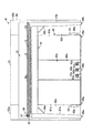
以下、本発明の一実施形態を図面を用いて説明する。図1ないし図3は、本発明にかかる楽器としての電子鍵盤楽器Mを示している。この電子鍵盤楽器Mは、楽器本体10と、楽器本体10の表面(上面)を開閉する蓋部21とダンパ機構30とを備えた蓋機構20と、楽器本体10の後部中央を支持する脚体ユニット40と、楽器本体10の前部両側をそれぞれ支持する脚部47a,47bとを備えている。また、楽器本体10の後部には、脚体ユニット40の両側部と上端部とを囲んだ門形の飾り板50が取り付けられている。
Hereinafter, an embodiment of the present invention will be described with reference to the drawings. 1 to 3 show an electronic keyboard instrument M as a musical instrument according to the present invention. The electronic keyboard instrument M includes a musical instrument
楽器本体10は、図1および図2の状態(演奏者側から見た状態であり、以下この方向に基づいて説明する。)で左右方向に長くなった箱状に形成され、両側部を構成する側板10a,10bの内面における上部手前側部分に、それぞれ拍子木11a,11bが取り付けられている。そして、拍子木11a,11b間に、電子鍵盤楽器Mを演奏するための複数の鍵からなる本発明の演奏操作子部としての鍵盤部12が設けられている。
The
また、楽器本体10の上面における鍵盤部12の後方に、複数の楽音パラメータ設定操作子等が設置された操作パネル部13が設けられている。そして、楽器本体10の上面における操作パネル部13の後方に、鍵盤部12および操作パネル部13よりも高さが高くなった蓋固定部22が取り付けられ、蓋固定部22の前端面に、折り畳み式の蓋部21がヒンジ連結されている。
In addition, an
また、図4に、電子鍵盤楽器Mから、蓋部21、蓋固定部22および飾り板50を取り外すとともに、楽器本体10の後部側部分の内部を露呈させた状態を示している。図4に示したように、楽器本体10内には、各種の回路基板等で構成される電子回路部14が設置されている。また、楽器本体10内における鍵盤部12および操作パネル部13の下方には、押鍵操作による押鍵力等を検出するための検出装置や、鍵の上下限位置を規制したり押鍵された鍵を上限位置に復帰させたりするための復帰機構等(図示せず)が設置されている。検出装置は、アクチュエーター、センサ、スイッチ基板等で構成され、復帰機構は、復帰ばね、鍵の下限位置や上限位置を規制するストッパ等で構成されている。
FIG. 4 shows a state in which the
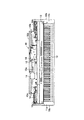
また、楽器本体10の後部における略中央には、凹部15が形成され、楽器本体10の後部両側には、切り欠き凹部16a,16bが形成されている。凹部15からは、電子鍵盤楽器Mを他の機器と接続するための接続コード15aを引き出せるようになっている。また、図5に示したように、楽器本体10の底板10cの左側端部は、固定部材17とねじ18とによって側板10aの内面下端部に固定され、底板10cの後端部は、固定部材17等と同様の固定部材(図示せず)によって背面板(図1および図4参照)10dの内面下端部に固定されている。
Further, a
蓋固定部22は、楽器本体10の平面視における後部側部分(図4における操作パネル部13の後方側部分)と略同一形状の板体で構成されており、下面後端縁部における両側部分と中央部分とが、固定部材17a,17b,17cによって楽器本体10の背面板10dに固定されている。また、蓋固定部22の下面における左側の端部近傍には、図5に示したように、係止部材23が、ねじ24aによって固定されている。この係止部材23は、蓋固定部22の下面に固定された固定片23aと、操作パネル部13の後端面部13aに沿って下方に延びる垂直片23bと、垂直片23bの下端から後方に向かって水平に延びる係合片23cとで構成されている。
The
また、操作パネル部13の左端部側部分は、固着部材25によって、楽器本体10の側板10aに固定されている。固着部材25は、側板10aの後部側の上部に固定された固定片25aと、上部が操作パネル部13の後端面部13aに沿い、下部が後端面部13aの下方に延びた係合片25bと、係合片25bの右側(図5では左側)の端部から操作パネル部13の下面に沿って前方に向かって水平に延びた垂直片25cと、垂直片25cの上端縁部における先端部と略中央部とから垂直方向に突出したねじ止め部25d,25eとで構成されている。そして、係合片25bの上部側部分の中央に水平方向に延びる係合穴部25fが形成されている。
Further, the left end side portion of the
固定片25aは、ねじ24bによって側板10aに固定され、ねじ止め部25d,25eは、ねじ24cによって、操作パネル部13の下面に形成されたボス部13b,13cに固着されている。そして、係止部材23と固着部材25とは、係合片23cが係合穴部25fに挿入されることにより係合しており、この係合によって、側板10a、操作パネル部13および蓋固定部22が連結されている。
The
側板10aの内面上部には、拍子木11aが固定部材19とねじ19aとを介して固定されており、側板10aの内面における拍子木11aの後方には、ダンパ機構30が取り付けられている。このダンパ機構30は、楽器本体10側に取り付けられたダンパ機構本体31と、ダンパ機構本体31と蓋部21とを連結するステー32とで構成されている。ダンパ機構本体31は、トルク軸33を備えたトルク軸ユニット(本体側部分は図示せず)と回動部材34とを備えている。
A
トルク軸ユニットは、円筒状の本体の内部に円筒状の摩擦部材を組み込み、摩擦部材の内部にトルク軸33を組み込んで構成されている。また、トルク軸ユニットは、本体に対するトルク軸33の一方向への回転を自由にし、他方向への回転をし難くするクラッチ機構も備えている。そして、摩擦部材とクラッチ機構との作用により、トルク軸ユニットは、トルク軸33が図5における時計回り方向に回転する際にその回転に対する抵抗力が大きくなり、反時計回り方向に回転する際の回転に対する抵抗力が小さくなるように構成されている。 The torque shaft unit is configured by incorporating a cylindrical friction member inside a cylindrical main body and incorporating a torque shaft 33 inside the friction member. The torque shaft unit also includes a clutch mechanism that freely rotates the torque shaft 33 in one direction with respect to the main body and makes it difficult to rotate in the other direction. Due to the action of the friction member and the clutch mechanism, when the torque shaft 33 rotates in the clockwise direction in FIG. 5, the resistance force to the rotation increases, and when the torque shaft 33 rotates in the counterclockwise direction. It is comprised so that the resistance force with respect to rotation may become small.
また、回動部材34は、長円形の板状体で構成されており、一端側に形成された穴部にトルク軸33を通した状態でトルク軸33に固定され、トルク軸33を中心として回動する。そして、回動部材34の他端側にはステー32の一端部(下端部)が回動可能な状態で取り付けられている。ステー32の下端部には支軸35が設けられており、この支軸35が回動部材34の他端側に設けられた穴部に回動可能に組み付けられている。
The rotating
蓋部21は、後蓋21aと前蓋21bとで構成され、蓋部21を閉じた状態(図3に実線で示した状態)での蓋固定部22の前端面上端縁部と後蓋21aの後端面上端縁部とが蝶番26aによって連結され、後蓋21aの前端面上端縁部と前蓋21bの後端面上端縁部とが蝶番26bによって連結されている。このため、図3に二点鎖線で示した状態から、後蓋21aと前蓋21bとを蝶番26aを中心として前方に回転させ、さらに、前蓋21bを蝶番26bを中心として前方に回転させることにより、蓋部21で鍵盤部12および操作パネル部13を覆うことができる。
The
また、図1および図2の状態における後蓋21aの左側の端部側部分に、ステー32の他端部(上端部)が後蓋21aに対して回動可能な状態で設けられている。後蓋21aには、支軸36を備えた連結部37が取り付けられており、支軸36に、ステー32の上端部近傍に設けられた穴部が回動可能に組み付けられている。このため、蓋部21の回動にともなって、ステー32が動いて回動部材34が回動し、ダンパ機構本体31がその動きをし難くしている。そして、前蓋21bの下面前端部における中央に、蓋部21を開いて折り畳んだ際に蓋部21を起立状態に支持するとともに、蓋部21を閉じた際に楽器本体10の上面前端部に当接して蓋部21を水平状態に維持させる支持部27が設けられている。
Further, the other end portion (upper end portion) of the
脚体ユニット40は、楽器本体10の下面における後部中央に、一体的に連結されて、楽器本体10の後部を支持しており、左右方向および上下方向に長くなった箱状に形成されている。この脚体ユニット40は、中央に位置する回路部品収容部40aと、回路部品収容部40aの両側に設けられたスピーカーボックス41a,41bとで構成されている。回路部品収容部40aは直方体の箱状に形成されている。そして、回路部品収容部40aの下部には、ペダル42a,42b,42cが水平方向に一定間隔を保って設けられている。
The
回路部品収容部40aの前壁部40bの下部には、穴部43a,43b,43cが形成されており、ペダル42a,42b,42cは、前部側部分をそれぞれ穴部43a,43b,43cから前方に突出させて上下に移動可能な状態で取り付けられている。回路部品収容部40a内における下部側部分は、穴部43a,43b,43cによって通気可能になっている。また、回路部品収容部40aの下部におけるペダル42a,42b,42cの近傍には、ペダルセンサや駆動用回路基板等(図示せず)が設けられている。さらに、回路部品収容部40aの後壁部には、凹部からなる電源取り入れ口44が形成され、その周縁部に通気孔(図示せず)が形成されている。そして、回路部品収容部40aの後壁部の内面に、電源トランス、回路基板、アンプ等の各種の機器が取り付けられている。
スピーカーボックス41a,41bは左右対称に形成された三角柱状の箱体で構成されており、回路部品収容部40aの両側に設置されている。そして、スピーカーボックス41a,41b内には、それぞれ楽音を発生するためのスピーカー(図示せず)が設置されている。これらの電子鍵盤楽器Mが備える電子回路や各種の機器等は、配線(図示せず)によって接続されている。また、スピーカーボックス41a,41bと回路部品収容部40aとの間の仕切り壁部には通気孔(図示せず)がそれぞれ設けられ、スピーカーボックス41a,41bの前面部は、音を通過させやすくするために多孔板で構成されている。
The
そして、スピーカーボックス41a,41bの外側面における下端部には、アングルからなる取付け用金具45a,45bが取り付けられている。また、回路部品収容部40aの下面後端部における両端部と中央部とにそれぞれ、支持突起46a,46b,46cが設けられている。この支持突起46a,46b,46cによって、脚体ユニット40は、下面が直接床面に接触しないように支持されている。
And the
また、脚部47a,47bは、それぞれ楽器本体10の前部における両端部に固定されて、楽器本体10の前部を支持している。この脚部47a,47bの上部における内側部および後側部は、補強部材48a,48bを介して楽器本体10の下面にも接続されており、これによってより強固に楽器本体10に連結されている。また、脚部47a,47bの下端面にも支持突起49a,49bが設けられており、電子鍵盤楽器Mの本体部分は、支持突起46a,46b,46c,49a,49bによって、床面との間に所定の隙間を設けて設置されている。
The
飾り板50は、上部中央を構成する中央部51と、中央部51の両側から下方に延びた左側部52aと右側部52bとを組み付けて構成されており、中央部51を蓋固定部22の上面に取り付け、左側部52aと右側部52bとをそれぞれ脚体ユニット40の側面に沿わせた状態で取り付けられている。そして、左側部52aと右側部52bの裏面下端部における内部側部分を、ねじ53によって取付け用金具45a,45bに固定することにより、電子鍵盤楽器Mの本体側に取り付けられている。
The
このように構成された電子鍵盤楽器Mを用いて演奏する際には、まず、電源取り入れ口44を介して電源を接続するとともに、接続コード15aを演奏に必要な機器、例えばコントローラ等に接続して演奏可能な状態にする。つぎに、蓋部21を開いて、鍵盤部12および操作パネル部13を露呈させる。この場合、まず、図3に実線で示した状態から前蓋21bを上方に持ち上げて、蝶番26bを中心として回転させ後蓋21aの上方に重ねる。ついで、重なった状態の後蓋21aと前蓋21bとを上方に持ち上げて、蝶番26aを中心として回転させ図3に二点鎖線で示した状態にする。
When playing with the electronic keyboard instrument M configured in this way, first, a power source is connected via the
後蓋21aと前蓋21bとが蝶番26aを中心として上方に回転する際に、ステー32は後蓋21aに引っ張られて上方に移動しようとする。また、トルク軸ユニットは、トルク軸33が反時計回りに回転する際には、回転に対する抵抗力が小さくなるように構成されているため、ステー32の上昇に追従してトルク軸33は容易に回転する。このため、後蓋21aと前蓋21bとを上方に回転させて開く操作がスムーズに行える。また、折り畳まれて回転した後蓋21aと前蓋21bとは、支持部27に支持されて起立状態を維持する。
When the
そして、スイッチをオン状態にして、鍵盤部12の各鍵、操作パネル部13の操作子およびペダル42a,42b,42c等を操作する。これによって、電子鍵盤楽器Mは、鍵盤部12、操作パネル部13の各種の操作子およびペダル42a,42b,42c等が有する機能に応じて、スピーカーから楽音、効果音などを発生させる。この場合、スピーカーから発生する楽音、効果音などのうち後方に向って広がる楽音等は、飾り板50によって前方に反射されより良好な音質となって演奏者に聞こえる。
Then, the switches are turned on to operate the keys of the
また、演奏が終了すると、スイッチをオフ状態にして蓋部21を閉じる。この場合、まず、図3に二点鎖線で示した状態から重なった状態の後蓋21aと前蓋21bとを、蝶番26aを中心として前方に向けて回転させる。この際、ステー32は後蓋21aに押されて下方に移動しようとする。このとき、ステー32は反作用の法則によって、後蓋21aを上方に押圧し、この力が蝶番26aを介して蓋固定部22の前方部分を押し上げようとする。この力に耐えるように係止部材23と固着部材25とによって楽器本体10の側板10aに蓋固定部22を固定している。
When the performance is finished, the switch is turned off and the
また、トルク軸ユニットは、トルク軸33が時計回りに回転する際には、回転に対する抵抗力が大きくなるように構成されているため、トルク軸33は、ステー32を介して負荷される蓋部21の荷重によりゆっくりと回転する。このため、蓋部21は、蓋固定部22や楽器本体10に衝撃を与えることなく徐々に下降していく。
Further, since the torque shaft unit is configured to increase the resistance to rotation when the torque shaft 33 rotates clockwise, the torque shaft 33 has a lid portion that is loaded via the
そして、前蓋21bを上方に持ち上げて、蝶番26bを中心として前方に回転させて図3に実線で示した状態にする。この場合、蓋部21は、支持部27に支持されて水平状態を維持する。また、蓋部21の開閉操作の際に、蓋固定部22には、大きな荷重が負荷されるが、固定部材17a,17b,17cおよび係止部材23と固着部材25との係合等によって、蓋固定部22は、楽器本体10にしっかりと固定されているため、がたつくことがない。また、蓋固定部22の上面には、飾り板50が取り付けられ、この飾り板50が蓋固定部22を下方に押え付ける重りになっているため、蓋固定部22の楽器本体10への固定がより確実になる。
Then, the
このように、本実施形態に係る電子鍵盤楽器Mでは、操作パネル部13の楽器本体10への固定を固着部材25を用いて行っている。そして、蓋固定部22に、固着部材25と係合可能な係止部材23を固定して、係止部材23を固着部材25に係合させることにより蓋固定部22の左側端部における前部を楽器本体10に固定している。したがって、操作パネル部13や蓋固定部22の全体にわたる各部分を多数のねじ等によって固定していくといった面倒な作業が不要になり、操作パネル部13や蓋固定部22の楽器本体10への組み付けが容易になる。
As described above, in the electronic keyboard musical instrument M according to the present embodiment, the
また、蓋固定部22は、表面から見えない下面後部が固定部材17a等によって楽器本体10の背面板10dに固定され、下面前部が係止部材23と固着部材25とによって楽器本体10の側板10aに固定されている。したがって、蓋固定部22は、固定部材17a等を表面に露呈させず、かつ前部をぐらつかせることなく固定されている。
The
また、楽器本体10側にダンパ機構本体31を取り付け、このダンパ機構本体31と後蓋21aとをステー32で連結している。このため、蓋部21を閉じる際の衝撃がなくなり、電子鍵盤楽器Mを長期間使用しても操作パネル部13や蓋固定部22の楽器本体10への固定部分に緩みが生じ難くなる。さらに、蓋固定部22の上面に飾り板50を取り付けているため、電子鍵盤楽器Mの見栄えがよくなるとともに、電子鍵盤楽器Mが発生する楽音の音質が向上する。また、この飾り板50によって、蓋固定部22が楽器本体10に押さえ付けられるようになり、蓋固定部22の楽器本体10への固定がより強固になる。
Further, a damper mechanism
また、本発明に係る電子鍵盤楽器Mは、前述した実施形態に限定するものでなく、適宜変更実施が可能である。例えば、前述した実施形態では、楽器を電子鍵盤楽器として、演奏操作子部を鍵盤部としているが、本発明に係る楽器は、これに限定するものでなく、演奏操作をするための演奏操作子部と操作パネル部とを備え、かつ開閉蓋部を楽器本体に取り付けるための蓋固定部を備えた楽器であればよい。 Further, the electronic keyboard instrument M according to the present invention is not limited to the above-described embodiment, and can be appropriately changed. For example, in the above-described embodiment, the musical instrument is an electronic keyboard musical instrument and the performance operator unit is a keyboard unit. However, the musical instrument according to the present invention is not limited to this, and a performance operator for performing a musical operation. Any musical instrument may be used as long as the musical instrument includes a lid fixing part for attaching the opening / closing lid part to the instrument body.
また、係止部材や固着部材の形状についても楽器を構成する他の部分の構造に応じて適宜変更することができる。さらに、前述した実施形態では、飾り板を、別体からなる中央部、左側部および右側部を組み付けたもので構成しているが、この飾り板は一体のもので構成してもよい。その他、本発明に係る楽器を構成する他の部分についても、本発明の技術的範囲内で適宜変更して実施することができる。 Further, the shapes of the locking member and the fixing member can be appropriately changed according to the structure of other parts constituting the musical instrument. Furthermore, in the above-described embodiment, the decorative plate is configured by assembling the central part, the left side part, and the right side part, which are formed separately, but this decorative plate may be configured as a single unit. In addition, other parts constituting the musical instrument according to the present invention can be implemented with appropriate modifications within the technical scope of the present invention.
10…楽器本体、10a,10b…側板、12…鍵盤部、13…操作パネル部、21…蓋部、22…蓋固定部、23…係止部材、25…固着部材、26a…蝶番、30…ダンパ機構、31…ダンパ機構本体、32…ステー、33…トルク軸、34…回動部材、M…電子鍵盤楽器。
DESCRIPTION OF
Claims (4)
前記楽器本体における前記演奏操作子の後方に設けられた操作パネル部と、
前記楽器本体における前記操作パネルの後方に取り付けられた蓋固定部と、
前記蓋固定部の前部にヒンジ部を介して回動可能に連結され、回動することにより前記演奏操作子部と前記操作パネル部との表面を開閉する蓋部と、
前記蓋固定部の前部に固定された係止部材と、
前記操作パネル部を前記楽器本体に固定する固着部材と
を備え、
前記蓋固定部の後部を固定部材によって前記楽器本体に固定し、前記蓋固定部の前部を前記係止部材と前記固着部材との係合によって前記楽器本体と前記操作パネル部とに対して固定することを特徴とする楽器。 An instrument body provided with a performance control section ;
An operation panel provided at the rear of the performance operator in the instrument body;
A lid fixed portion attached to the rear of the operation panel in the instrument the body,
A lid portion that is pivotably connected to a front portion of the lid fixing portion via a hinge portion, and that opens and closes the surfaces of the performance operator portion and the operation panel portion by turning;
A locking member fixed to the front portion of the lid fixing portion ;
A fixing member for fixing the operation panel unit to the instrument body;
The rear portion of the lid fixing portion is fixed to the instrument body by a fixing member, and the front portion of the lid fixing portion is engaged with the instrument body and the operation panel portion by engagement of the locking member and the fixing member. A musical instrument characterized by being fixed .
Priority Applications (1)
| Application Number | Priority Date | Filing Date | Title |
|---|---|---|---|
| JP2004006404A JP4479246B2 (en) | 2004-01-14 | 2004-01-14 | Musical instrument |
Applications Claiming Priority (1)
| Application Number | Priority Date | Filing Date | Title |
|---|---|---|---|
| JP2004006404A JP4479246B2 (en) | 2004-01-14 | 2004-01-14 | Musical instrument |
Publications (2)
| Publication Number | Publication Date |
|---|---|
| JP2005202004A JP2005202004A (en) | 2005-07-28 |
| JP4479246B2 true JP4479246B2 (en) | 2010-06-09 |
Family
ID=34820381
Family Applications (1)
| Application Number | Title | Priority Date | Filing Date |
|---|---|---|---|
| JP2004006404A Expired - Fee Related JP4479246B2 (en) | 2004-01-14 | 2004-01-14 | Musical instrument |
Country Status (1)
| Country | Link |
|---|---|
| JP (1) | JP4479246B2 (en) |
-
2004
- 2004-01-14 JP JP2004006404A patent/JP4479246B2/en not_active Expired - Fee Related
Also Published As
| Publication number | Publication date |
|---|---|
| JP2005202004A (en) | 2005-07-28 |
Similar Documents
| Publication | Publication Date | Title |
|---|---|---|
| CN100593810C (en) | Keyboard instrument | |
| JP5487608B2 (en) | Electronic keyboard instrument | |
| JP6555644B2 (en) | Keyboard instrument | |
| JP6103336B2 (en) | Keyboard instrument | |
| CN101751913B (en) | Electric keyboard instrument | |
| JP2013242385A (en) | Keyboard unit and keyboard musical instrument | |
| JP5161463B2 (en) | Electronic keyboard instrument | |
| JP4479246B2 (en) | Musical instrument | |
| JP2015060112A (en) | Electronic keyboard musical instrument | |
| JP2008299169A (en) | Speaker unit for electronic musical instrument | |
| JP5381458B2 (en) | Electronic keyboard instrument | |
| JP2020060604A (en) | Electronic keyboard musical instrument and electronic keyboard device | |
| JP2008241760A (en) | Electronic keyboard musical instrument | |
| JP6252109B2 (en) | Keyboard instrument | |
| JP6548001B2 (en) | Keyboard instrument | |
| JP6198102B2 (en) | Keyboard instrument | |
| JP4526496B2 (en) | Grand type electronic piano | |
| JP4062258B2 (en) | Electronic keyboard instrument | |
| JP4052252B2 (en) | Keyboard instrument | |
| JP2011070109A (en) | Keyboard device of electronic keyboard instrument | |
| JP2005107462A (en) | Keyboard covering device of electronic keyboard musical instrument | |
| JP2005266176A (en) | Electronic keyed instrument | |
| JP3933038B2 (en) | Keyboard instrument | |
| JP2011053434A (en) | Keyboard instrument | |
| JP7172424B2 (en) | electronic keyboard instrument |
Legal Events
| Date | Code | Title | Description |
|---|---|---|---|
| A621 | Written request for application examination |
Free format text: JAPANESE INTERMEDIATE CODE: A621 Effective date: 20060424 |
|
| A977 | Report on retrieval |
Free format text: JAPANESE INTERMEDIATE CODE: A971007 Effective date: 20081121 |
|
| A131 | Notification of reasons for refusal |
Free format text: JAPANESE INTERMEDIATE CODE: A131 Effective date: 20081126 |
|
| A521 | Written amendment |
Free format text: JAPANESE INTERMEDIATE CODE: A523 Effective date: 20090121 |
|
| TRDD | Decision of grant or rejection written | ||
| A01 | Written decision to grant a patent or to grant a registration (utility model) |
Free format text: JAPANESE INTERMEDIATE CODE: A01 Effective date: 20100223 |
|
| A01 | Written decision to grant a patent or to grant a registration (utility model) |
Free format text: JAPANESE INTERMEDIATE CODE: A01 |
|
| A61 | First payment of annual fees (during grant procedure) |
Free format text: JAPANESE INTERMEDIATE CODE: A61 Effective date: 20100308 |
|
| FPAY | Renewal fee payment (event date is renewal date of database) |
Free format text: PAYMENT UNTIL: 20130326 Year of fee payment: 3 |
|
| R150 | Certificate of patent or registration of utility model |
Ref document number: 4479246 Country of ref document: JP Free format text: JAPANESE INTERMEDIATE CODE: R150 Free format text: JAPANESE INTERMEDIATE CODE: R150 |
|
| FPAY | Renewal fee payment (event date is renewal date of database) |
Free format text: PAYMENT UNTIL: 20140326 Year of fee payment: 4 |
|
| LAPS | Cancellation because of no payment of annual fees |