JP4476120B2 - Method and apparatus for shielding the tip of a catheter introducer needle - Google Patents
Method and apparatus for shielding the tip of a catheter introducer needle Download PDFInfo
- Publication number
- JP4476120B2 JP4476120B2 JP2004521478A JP2004521478A JP4476120B2 JP 4476120 B2 JP4476120 B2 JP 4476120B2 JP 2004521478 A JP2004521478 A JP 2004521478A JP 2004521478 A JP2004521478 A JP 2004521478A JP 4476120 B2 JP4476120 B2 JP 4476120B2
- Authority
- JP
- Japan
- Prior art keywords
- needle
- distal
- elongate member
- shield
- needle assembly
- Prior art date
- Legal status (The legal status is an assumption and is not a legal conclusion. Google has not performed a legal analysis and makes no representation as to the accuracy of the status listed.)
- Expired - Lifetime
Links
Images


Classifications
-
- A—HUMAN NECESSITIES
- A61—MEDICAL OR VETERINARY SCIENCE; HYGIENE
- A61M—DEVICES FOR INTRODUCING MEDIA INTO, OR ONTO, THE BODY; DEVICES FOR TRANSDUCING BODY MEDIA OR FOR TAKING MEDIA FROM THE BODY; DEVICES FOR PRODUCING OR ENDING SLEEP OR STUPOR
- A61M5/00—Devices for bringing media into the body in a subcutaneous, intra-vascular or intramuscular way; Accessories therefor, e.g. filling or cleaning devices, arm-rests
- A61M5/178—Syringes
- A61M5/31—Details
- A61M5/32—Needles; Details of needles pertaining to their connection with syringe or hub; Accessories for bringing the needle into, or holding the needle on, the body; Devices for protection of needles
- A61M5/3205—Apparatus for removing or disposing of used needles or syringes, e.g. containers; Means for protection against accidental injuries from used needles
- A61M5/321—Means for protection against accidental injuries by used needles
- A61M5/3243—Means for protection against accidental injuries by used needles being axially-extensible, e.g. protective sleeves coaxially slidable on the syringe barrel
- A61M5/3273—Means for protection against accidental injuries by used needles being axially-extensible, e.g. protective sleeves coaxially slidable on the syringe barrel freely sliding on needle shaft without connection to syringe or needle
-
- A—HUMAN NECESSITIES
- A61—MEDICAL OR VETERINARY SCIENCE; HYGIENE
- A61M—DEVICES FOR INTRODUCING MEDIA INTO, OR ONTO, THE BODY; DEVICES FOR TRANSDUCING BODY MEDIA OR FOR TAKING MEDIA FROM THE BODY; DEVICES FOR PRODUCING OR ENDING SLEEP OR STUPOR
- A61M25/00—Catheters; Hollow probes
- A61M25/01—Introducing, guiding, advancing, emplacing or holding catheters
- A61M25/06—Body-piercing guide needles or the like
- A61M25/0612—Devices for protecting the needle; Devices to help insertion of the needle, e.g. wings or holders
- A61M25/0618—Devices for protecting the needle; Devices to help insertion of the needle, e.g. wings or holders having means for protecting only the distal tip of the needle, e.g. a needle guard
- A61M25/0625—Devices for protecting the needle; Devices to help insertion of the needle, e.g. wings or holders having means for protecting only the distal tip of the needle, e.g. a needle guard with a permanent connection to the needle hub, e.g. a guiding rail, a locking mechanism or a guard advancement mechanism
-
- A—HUMAN NECESSITIES
- A61—MEDICAL OR VETERINARY SCIENCE; HYGIENE
- A61M—DEVICES FOR INTRODUCING MEDIA INTO, OR ONTO, THE BODY; DEVICES FOR TRANSDUCING BODY MEDIA OR FOR TAKING MEDIA FROM THE BODY; DEVICES FOR PRODUCING OR ENDING SLEEP OR STUPOR
- A61M5/00—Devices for bringing media into the body in a subcutaneous, intra-vascular or intramuscular way; Accessories therefor, e.g. filling or cleaning devices, arm-rests
- A61M5/178—Syringes
- A61M5/31—Details
- A61M5/32—Needles; Details of needles pertaining to their connection with syringe or hub; Accessories for bringing the needle into, or holding the needle on, the body; Devices for protection of needles
- A61M5/3205—Apparatus for removing or disposing of used needles or syringes, e.g. containers; Means for protection against accidental injuries from used needles
- A61M5/321—Means for protection against accidental injuries by used needles
- A61M5/3243—Means for protection against accidental injuries by used needles being axially-extensible, e.g. protective sleeves coaxially slidable on the syringe barrel
- A61M5/3245—Constructional features thereof, e.g. to improve manipulation or functioning
- A61M2005/3247—Means to impede repositioning of protection sleeve from needle covering to needle uncovering position
-
- A—HUMAN NECESSITIES
- A61—MEDICAL OR VETERINARY SCIENCE; HYGIENE
- A61M—DEVICES FOR INTRODUCING MEDIA INTO, OR ONTO, THE BODY; DEVICES FOR TRANSDUCING BODY MEDIA OR FOR TAKING MEDIA FROM THE BODY; DEVICES FOR PRODUCING OR ENDING SLEEP OR STUPOR
- A61M5/00—Devices for bringing media into the body in a subcutaneous, intra-vascular or intramuscular way; Accessories therefor, e.g. filling or cleaning devices, arm-rests
- A61M5/178—Syringes
- A61M5/31—Details
- A61M5/32—Needles; Details of needles pertaining to their connection with syringe or hub; Accessories for bringing the needle into, or holding the needle on, the body; Devices for protection of needles
- A61M5/3205—Apparatus for removing or disposing of used needles or syringes, e.g. containers; Means for protection against accidental injuries from used needles
- A61M5/321—Means for protection against accidental injuries by used needles
- A61M5/3243—Means for protection against accidental injuries by used needles being axially-extensible, e.g. protective sleeves coaxially slidable on the syringe barrel
- A61M5/3275—Means for protection against accidental injuries by used needles being axially-extensible, e.g. protective sleeves coaxially slidable on the syringe barrel being connected to the needle hub or syringe by radially deflectable members, e.g. longitudinal slats, cords or bands
Landscapes
- Health & Medical Sciences (AREA)
- Life Sciences & Earth Sciences (AREA)
- Engineering & Computer Science (AREA)
- Anesthesiology (AREA)
- General Health & Medical Sciences (AREA)
- Biomedical Technology (AREA)
- Heart & Thoracic Surgery (AREA)
- Hematology (AREA)
- Veterinary Medicine (AREA)
- Animal Behavior & Ethology (AREA)
- Public Health (AREA)
- Biophysics (AREA)
- Pulmonology (AREA)
- Vascular Medicine (AREA)
- Environmental & Geological Engineering (AREA)
- Infusion, Injection, And Reservoir Apparatuses (AREA)
- Media Introduction/Drainage Providing Device (AREA)
Abstract
Description
本発明は、針の末端を安全に遮へいしその末端が遮へいされた後、針遮へいアセンブリに対する針先端の動きを制限するように構成された針遮へいアセンブリに関する。 The present invention relates to a needle shield assembly that is configured to safely shield the distal end of a needle and limit the movement of the needle tip relative to the needle shield assembly after the distal end is shielded.
関連出願
本願は、2002年6月20日に出願された米国の仮出願60/390,499号の35USC119条(e)項による利益を求めるものである。
RELATED APPLICATION This application seeks the benefit of
本願は、先に出願された出願であって、それぞれが参考のために示される次の出願に関連したものである。すなわち、本出願は、2002年12月17日の出願10/320,960号の一部継続出願であり、上記出願10/320,960号は2000年2月4日の出願09/499,331号の継続出願であり、上記出願09/499,331号は1999年5月14日の出願09/312,335号で現在特許されている特許6,379,333号の一部継続出願であり、また、上記出願09/312,335号は1998年4月8日の出願09/057,718号で現在特許されている特許6,004,294号の一部継続出願である。
This application is related to the following applications that have been previously filed and each is shown for reference. That is, the present application is a continuation-in-part of
本出願は、また、2000年11月21日の出願09/717,148号の一部継続出願であり、上記出願09/717,148号は出願09/590,600号で現在放棄されているものの一部継続出願であり、上記出願09/590,600号は1999年5月14日の出願09/312,335号で現在特許されている特許6,379,333号の一部継続出願であり、また、上記出願09/312,335号は1998年4月8日の出願09/057,718号で現在特許されている特許6,004,294号の一部継続出願である。 This application is also a continuation-in-part of application 09 / 717,148 of November 21, 2000, which application 09 / 717,148 is currently abandoned in application 09 / 590,600. The above-mentioned application 09 / 590,600 is a partial continuation application of the patent No. 6,379,333 currently patented in the application 09 / 312,335 on May 14, 1999. In addition, the above-mentioned application 09 / 312,335 is a continuation-in-part application of the patent No. 6,004,294 currently patented in the application 09 / 57,718 of April 8, 1998.
静脈(IV)カテーテルは、通常の塩水、種々の薬物、また、完全非経口栄養のような液体を、患者または患者から引き出した血液の中に注入するために用いられる。抹消静脈カテーテルは比較的短いものとなる傾向にあり、約1.5インチの長さのものである。静脈カテーテルの通常のタイプはオーバーニードル抹消静脈カテーテルである。その名が示すように、オーバーニードルカテーテルは鋭い末端を持った導入針を覆うように装着される。カテーテルと導入針はそれらが組み合わされると、導入針の末端がカテーテルの末端の先まで延在するともに上記針の斜面が患者の皮膚から離れる方向を向いたものとなる。 Intravenous (IV) catheters are used to infuse normal saline, various drugs, and fluids such as complete parenteral nutrition into the patient or blood drawn from the patient. Peripheral venous catheters tend to be relatively short and are approximately 1.5 inches long. A common type of venous catheter is an overneedle peripheral venous catheter. As the name implies, an overneedle catheter is mounted over an introducer needle with a sharp end. When the catheter and introducer needle are combined, the distal end of the introducer needle extends beyond the distal end of the catheter and the slope of the needle faces away from the patient's skin.
カテーテルと導入針のアセンブリは、浅い角度で患者の皮膚を通り抹消血管(すなわち、より小さい血管であって心臓には直接つながっていないが心臓に直接つながっている主要な血管の枝の1つである血管)内に挿入される。アセンブリが血管内の適切な位置に置かれたことを確認するため、医者は針の中や針の基部に近い位置に位置するフラッシュバック室の中に血液の逆流があることを確かめる。通常、フラッシュバック室は針ハブの一部として形成される。適切な位置に置かれたことが確認されると、医者は、導入針およびカテーテルの末端に近い患者の皮膚を押して血管に圧力を与える。この指による加圧によって、導入針を通るそれ以上の血液の流れが遮断される。医者は、カテーテルをそのままにして導入針を抜きとり、液体取り扱い装置をカテーテルハブに取り付ける。導入針がカテーテルから抜き取られると、その針は「血液で汚染された鋭利物」とみなされ、適切に扱うべきものとなる。 The catheter and introducer needle assembly is a peripheral blood vessel (ie, a smaller blood vessel that is not directly connected to the heart but directly connected to the heart, but is connected to the heart at a shallow angle). Inserted in a certain blood vessel). To confirm that the assembly is in place in the blood vessel, the physician verifies that there is a backflow of blood in the flashback chamber located in the needle or near the base of the needle. Usually, the flashback chamber is formed as part of the needle hub. Once confirmed to be in place, the physician presses the patient's skin near the distal end of the introducer needle and catheter to apply pressure to the vessel. This finger pressurization blocks further blood flow through the introducer needle. The doctor leaves the catheter and removes the introducer needle and attaches the liquid handling device to the catheter hub. When the introducer needle is withdrawn from the catheter, the needle is considered a “blood-contaminated sharp” and should be handled appropriately.
近年、医者が患者の血液で汚染されることに大いに関心がもたれ、また、「血液で汚染された鋭利物」は直ちに廃棄されなければならないことが認識されてきている。この関心によって、ある部分、感染した人から他の人に体液の交換によってうつる病気の広がりの危険性を低減することができる。従って、感染した人の体液に触れることを避けることは望ましいことである。針を遮へいする様々なものが開発されている。一般に、そのような針シールドはそれらの本来の目的に都合がよいが改善の余地がある。例えば、針シールドの中にはかさばるものがあり、これは使用することが難しくあるいは操作に特別の機能ないし技量が必要となる。 In recent years, it has been recognized that doctors are very interested in being contaminated with the blood of a patient and that “sharp objects contaminated with blood” must be immediately discarded. This concern can reduce the risk of spreading the disease that in some parts by exchanging fluid from one infected person to another. Therefore, it is desirable to avoid touching the body fluid of an infected person. Various things have been developed to shield the needle. In general, such needle shields are convenient for their original purpose, but there is room for improvement. For example, some needle shields are bulky and are difficult to use or require special functions or skills to operate.
本発明の一態様では、医療用針アセンブリは、本体および先端を有した針カニューレを含む。前記先端は前記カニューレの末端に配される。細長部材が前記針カニューレに接続点で固定して取り付けられる。前記細長部材は前記針カニューレから離れた非付勢状態から前記針カニューレに近い付勢状態に移ることが可能である。 In one aspect of the present invention, a medical needle assembly includes a needle cannula having a body and a tip. The tip is disposed at the end of the cannula. An elongate member is fixedly attached to the needle cannula at a connection point. The elongate member can transition from a non-biased state away from the needle cannula to a biased state near the needle cannula.
本発明の上記態様の実施では、前記針カニューレはノッチを定め、該ノッチを通って前記細長部材が延在する。針カニューレには内壁が含まれ、該内壁に前記細長部材が取り付けられる。フェルールが前記針カニューレに取り付けられ、前記細長部材は前記フェルールに前記接続点で取り付けられる。前記細長部材は前記フェルールと一体に形成される。第2フェルールは第1フェルールと前記先端との間で前記針カニューレに取り付けられ、第2細長部材は、前記第2フェルールに取り付けられるとともに、前記第2フェルールから基部側に向けて延在する。前記第1フェルールと前記第2フェルールとは一体に形成される。前記細長部材は前記針カニューレと一体に形成される。前記細長部材は前記針カニューレに配されるノッチによって定められる。前記細長部材はリーフスプリングまたは線材である。前記リーフスプリングは付勢された状態で前記ノッチ内に配される。 In the implementation of the above aspect of the invention, the needle cannula defines a notch through which the elongated member extends. The needle cannula includes an inner wall to which the elongate member is attached. A ferrule is attached to the needle cannula and the elongated member is attached to the ferrule at the connection point. The elongated member is formed integrally with the ferrule. A second ferrule is attached to the needle cannula between the first ferrule and the tip, and a second elongated member is attached to the second ferrule and extends from the second ferrule toward the base side. The first ferrule and the second ferrule are integrally formed. The elongate member is integrally formed with the needle cannula. The elongate member is defined by a notch disposed in the needle cannula. The elongated member is a leaf spring or a wire. The leaf spring is arranged in the notch in a biased state.
本発明の他の態様では、医療用針アセンブリは、本体および先端を有した針カニューレを含む。前記先端が前記カニューレの末端に配される。細長部材は第1端部と第2端部とを有する。前記第1端部は前記針カニューレの本体に接続点で固定して取り付けられ、前記第2端部が前記針本体から半径方向外側に延びる。シールドは、前記針にスライド可能に装着されて基部側位置から末端側位置へ動くことができる。前記シールドは、中央室、末端側端および基部側端を有したシールド本体と、該シールド本体に固定され、開口を定めたプレートと、を備える。前記シールドが前記基部側位置から前記末端側位置へ動かされるとき、前記プレートは前記細長部材の前記第2端部を前記針カニューレの近くに移動させて、前記細長部材が前記開口を通ることができるようにする。 In another aspect of the invention, a medical needle assembly includes a needle cannula having a body and a tip. The tip is disposed at the end of the cannula. The elongate member has a first end and a second end. The first end is fixedly attached to the needle cannula body at a connection point, and the second end extends radially outward from the needle body. The shield is slidably mounted on the needle and can move from a proximal position to a distal position. The shield includes a shield body having a central chamber, a distal end and a base end, and a plate fixed to the shield body and defining an opening. When the shield is moved from the proximal position to the distal position, the plate moves the second end of the elongate member closer to the needle cannula so that the elongate member passes through the opening. It can be so.
本発明の上記態様の特定の実施では、前記シールドが末端位置にあるとき、前記細長部材の前記第2端部は前記針本体から半径方向外側に延びて、前記細長部材が前記開口を通過することを防ぐ。前記細長部材はリーフスプリングまたは線材である。前記開口は開口半径を規定し、また、前記細長部材の前記第2端部は部材半径を規定し、前記開口半径は前記部材半径より小さい。特徴部が前記カニューレの前記本体に固定され、前記特徴部は特徴部半径を規定し、前記開口半径は前記特徴部半径より小さい。前記プレートは円筒形状であり、前記開口は円筒形状である。前記針本体によってノッチが定められ、前記細長部材は前記ノッチに隣接して配される。前記シールドは前記接続点と前記針の先端との間の距離より長い長さを有する。 In a particular implementation of the above aspect of the invention, when the shield is in the distal position, the second end of the elongate member extends radially outward from the needle body and the elongate member passes through the opening. To prevent that. The elongated member is a leaf spring or a wire. The opening defines an opening radius, and the second end of the elongate member defines a member radius, the opening radius being smaller than the member radius. A feature is secured to the body of the cannula, the feature defining a feature radius, and the opening radius being smaller than the feature radius. The plate has a cylindrical shape, and the opening has a cylindrical shape. A notch is defined by the needle body, and the elongated member is disposed adjacent to the notch. The shield has a length longer than the distance between the connection point and the tip of the needle.
本発明の他の態様では、医療用針アセンブリは、本体および先端を有した針カニューレを含む。前記先端が前記カニューレの末端に配される。特徴部が前記カニューレの本体に固定される。シールドが前記針にスライド可能に装着されて基部側位置と末端側位置との間を動くことができる。前記シールドは、中央室、末端側端および基部側端を有したシールド本体と、該シールド本体の前記基部側端に固定され、開口を定めたプレートと、を備える。前記シールドが前記基部側位置にあるとき、前記針が少なくとも部分的に前記中央室内に配され、前記針が前記プレートの開口を通って延在する。前記開口はそのサイズが定められることにより針本体の通過を可能とし、前記特徴部が通過しないようにする。可橈性部材は第1端部、第2端部および厚みを有する。前記第1端部は前記シールド本体に固定して取り付けられるとともに前記中央室内に配される。前記可撓性部材の前記第2端部は半径方向内側に向けて前記中央室内に付勢される。前記シールドが前記基部側位置にあるとき、前記針本体は前記可橈性部材を前記シールド本体に形成された溝内に付勢する。前記シールド本体が末端側位置にあるとき、前記可撓性部材は前記溝から出て前記針カニューレと前記シールド本体との間に配される。 In another aspect of the invention, a medical needle assembly includes a needle cannula having a body and a tip. The tip is disposed at the end of the cannula. A feature is secured to the body of the cannula. A shield is slidably mounted on the needle and can move between a proximal position and a distal position. The shield includes a shield body having a central chamber, a distal end and a base end, and a plate fixed to the base end of the shield body and defining an opening. When the shield is in the proximal position, the needle is at least partially disposed in the central chamber and the needle extends through the opening in the plate. The opening is sized to allow passage of the needle body and prevent passage of the feature. The flexible member has a first end, a second end, and a thickness. The first end is fixedly attached to the shield body and is disposed in the central chamber. The second end portion of the flexible member is urged into the central chamber toward the inside in the radial direction. When the shield is in the base position, the needle body biases the flexible member into a groove formed in the shield body. When the shield body is in the distal position, the flexible member exits the groove and is disposed between the needle cannula and the shield body.
本発明の上記態様の特定の実施では、前記可撓性部材の厚みは、前記中央室内で前記溝の外にあるとき、前記可撓性部材は前記特徴部の通過を阻止するものである。前記可撓性部材は前記シールドに接続点で接続する線材であり、前記溝は該接続点から末端側へ延在し、また、前記シールドが前記末端側位置へ移動させられるとき、前記線材は末端方向に移る。 In a particular implementation of the above aspect of the invention, the flexible member prevents passage of the feature when the thickness of the flexible member is outside the groove in the central chamber. The flexible member is a wire connected to the shield at a connection point, the groove extends from the connection point to the distal side, and when the shield is moved to the distal side position, the wire is Move towards the end.
本発明の他の態様では、医療用針アセンブリは、本体および先端を有した針カニューレを含む。前記先端が前記カニューレの末端に配される。フェルールが前記針本体に前記先端に近い位置で取り付けられる。細長部材が、前記フェルールに取り付けられ、前記針本体から半径方向外側に延びる自由端を有している。前記自由端が部材半径を規定する。シールドは、前記針にスライド可能に装着されて基部側位置と末端側位置との間を動くことができる。このシールドは、中央室、末端側端および基部側端を有したシールド本体と、該シールド本体の前記基部側端に固定され、厚みを有し開口半径を持った開口を定めたプレートと、を備える。前記シールドが前記基部側位置にあるとき、前記針は少なくとも部分的に前記中央室内に配され、前記針は前記プレートの前記開口を通って延在する。前記開口半径は前記部材半径より小さい。 In another aspect of the invention, a medical needle assembly includes a needle cannula having a body and a tip. The tip is disposed at the end of the cannula. A ferrule is attached to the needle body at a position close to the tip. An elongate member is attached to the ferrule and has a free end extending radially outward from the needle body. The free end defines a member radius. The shield is slidably mounted on the needle and can move between a proximal position and a distal position. The shield includes a shield body having a central chamber, a distal end and a base side end, and a plate fixed to the base side end of the shield body and having a thickness and an opening radius. Prepare. When the shield is in the proximal position, the needle is at least partially disposed within the central chamber and the needle extends through the opening in the plate. The opening radius is smaller than the member radius.
本発明の上記態様の特定の実施では、末端側フェルールが、基部側フェルールより末端側で前記針本体に取り付けられる。末端側細長部材が、前記末端側フェルールに取り付けられ、基部側の方向に延在する。前記末端側細長部材には前記針本体から外側に第2部材半径まで付勢される第2自由端が含まれる。前記開口半径は前記第2部材半径より小さい。前記基部側細長部材の自由端と前記末端側細長部材の自由端は前記プレートの厚みより大きな距離だけ離れている。前記基部側フェルールと前記末端側フェルールは一体に形成される。 In a particular implementation of the above aspect of the invention, a distal ferrule is attached to the needle body distal to the proximal ferrule. A distal elongated member is attached to the distal ferrule and extends in a proximal direction. The distal elongate member includes a second free end that is biased outwardly from the needle body to a second member radius. The opening radius is smaller than the second member radius. The free end of the base side elongated member and the free end of the distal side elongated member are separated by a distance greater than the thickness of the plate. The base side ferrule and the distal side ferrule are integrally formed.
本発明の他の態様では、医療用針アセンブリは、本体および先端を有した針カニューレを含む。前記先端が前記カニューレの末端に配される。細長部材が第1端部と第2端部とを有する。前記第1端部は前記針カニューレの本体に接続点で固定して取り付けられ、前記第2端部が前記針本体から半径方向外側に延びる。シールドが、前記針にスライド可能に装着されて基部側位置と末端側位置との間を動くことができる。このシールドは、中央室、末端側端および基部側端を有したシールド本体を含む。基部側プレートが、前記シールド本体の前記基部側端に固定される。末端側プレートが、基部側開口を定めた前記シールド本体に前記基部側プレートより末端側で固定され、末端側開口を定める。前記シールドが前記基部側位置にあるとき、前記針が少なくとも部分的に前記中央室内にあり、前記針が前記基部側開口および前記末端側開口を通って延在する。前記末端側開口は前記細長部材が基部側の方向に通過することをできるようにしたものであり、また、前記細長部材が末端側方向に通過することを阻止する。 In another aspect of the invention, a medical needle assembly includes a needle cannula having a body and a tip. The tip is disposed at the end of the cannula. The elongate member has a first end and a second end. The first end is fixedly attached to the needle cannula body at a connection point, and the second end extends radially outward from the needle body. A shield is slidably mounted on the needle and can move between a proximal position and a distal position. The shield includes a shield body having a central chamber, a distal end, and a proximal end. A base side plate is fixed to the base side end of the shield body. A distal side plate is fixed to the shield body defining the base side opening on the distal side with respect to the base side plate to define the distal side opening. When the shield is in the proximal position, the needle is at least partially in the central chamber and the needle extends through the proximal opening and the distal opening. The distal opening allows the elongate member to pass in the direction of the base, and prevents the elongate member from passing in the distal direction.
本発明の上記態様の特定の実施では、前記細長部材は前記針本体と一体に形成される。特徴部が、前記針本体上に位置し、前記細長部材および前記特徴部は一体に形成される。1つ以上の細長部材が前記フェルールに取り付けられる。前記末端側プレートは前記シールド本体に軸中心の回動が可能に取り付けられる。 In a particular implementation of the above aspect of the invention, the elongated member is formed integrally with the needle body. A feature is located on the needle body, and the elongated member and the feature are integrally formed. One or more elongated members are attached to the ferrule. The end plate is attached to the shield body so as to be pivotable about its axis.
本発明の他の態様では、針を製造する方法は、本体および先端を有した針カニューレであって、前記先端が前記カニューレの末端に配された針カニューレを用意することを含む。細長部材が前記針カニューレに接続点で固定して取り付けられる。前記細長部材が前記針カニューレから離れた非付勢状態から前記針カニューレに近い付勢状態に移ることが可能である。 In another aspect of the invention, a method of manufacturing a needle includes providing a needle cannula having a body and a tip, the tip being disposed at a distal end of the cannula. An elongate member is fixedly attached to the needle cannula at a connection point. The elongate member can transition from a non-biased state away from the needle cannula to a biased state near the needle cannula.
本発明の他の態様では、針をシールドする方法は、本体および先端を有した針カニューレであって、前記先端が前記カニューレの末端に配された針カニューレを用意することを含む。細長部材は、第1端部と第2端部とを有し、前記針カニューレの本体に接続点で固定して取り付けられて、前記第2端部が前記針本体から半径方向外側に延びるようにする。シールドは前記針に沿って基部側位置から末端側位置へスライドし、前記シールドが前記基部側位置から末端側位置へ動くとき、前記シールド上のプレートは前記細長部材の前記第2端部を前記針カニューレの近くに移動させて、前記細長部材が前記開口を通ることができるようにする。本発明の上記態様の特定の実施では、前記開口を通過した後、前記細長部材を半径方向外側に変位させる。 In another aspect of the invention, a method for shielding a needle includes providing a needle cannula having a body and a tip, the tip being disposed at a distal end of the cannula. The elongate member has a first end and a second end and is fixedly attached to the needle cannula body at a connection point such that the second end extends radially outward from the needle body. To. A shield slides from the proximal position to the distal position along the needle, and when the shield moves from the proximal position to the distal position, the plate on the shield causes the second end of the elongate member to move the second end. Move close to the needle cannula to allow the elongate member to pass through the opening. In a particular implementation of the above aspect of the invention, after passing through the opening, the elongate member is displaced radially outward.
好適な実施形態を示す図において同じ参照番号は同じ要素を示している。 In the figures illustrating the preferred embodiment, the same reference numbers refer to the same elements.
本明細書において使われる“基部の”という用語は、本発明のカテーテルと針のアセンブリにおける位置であって、装置が通常動作で用いられるときに、その装置を使用する医者に最も近くその装置を接続して用いられる患者から最も遠い位置を言っている。反対に、“末端の”という用語は、本発明のカテーテルと針のアセンブリにおける位置であって、装置が通常動作で用いられるときに、その装置を使用する医者から最も遠くその装置を接続して用いられる患者に最も近い位置を言っている。 As used herein, the term “base” refers to the position in the catheter and needle assembly of the present invention that, when the device is used in normal operation, is closest to the physician using the device. Says the farthest position from the patient used in connection. Conversely, the term “terminal” refers to a position in the catheter and needle assembly of the present invention that connects the device farthest from the physician using the device when the device is used in normal operation. Says the position closest to the patient used.
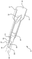
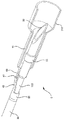
導入針とカテーテルのアセンブリ100(オーバーニードルカテーテルとも言う)はカテーテルアダプタ8を含んでおり、このアダプタはその末端部に取り付けられたカテーテル108を有している。アダプタ8にはウイング130を設けることもできる。使用する前および挿入する間(図1に示される)、本体および先端32を有した針カニューレ30はカテーテル内に配置され、先端すなわち末端32はカテーテルの末端から外に出ている。針の基部端は針ハブ110に取り付けられている。針ハブ110に指グリップ120を組み込むこともできる。このような構造は、ウイング130と協働して、介護する人がカテーテルの挿入に際して、参考のために示される2001年5月25日出願の特許文献1に説明されるような様々な手法を用いることを可能とするものである。
The introducer needle and catheter assembly 100 (also referred to as an over-needle catheter) includes a catheter adapter 8, which has a
シールドは、針シールドアセンブリ5として参照されるものであり、針30の周囲、好ましくは、図1に示すように、針ハブ110とカテーテルアダプタ8との間に配置される。あるいは、針シールドアセンブリ5は、完全にカテーテルアダプタの中に配置されてもよく、これも本発明の実施態様とすることができる。針30とシールド5の組み合わせは、概略、医療針アセンブリ700(図2参照)として参照されるものである。当然のことながら、本発明の実施形態は、カテーテルアダプタの中の針シールドアセンブリ、針ハブとカテーテルアダプタとの間に配置される針シールドアセンブリ、または、針に沿った他の位置におけるアセンブリのいずれでも実施できる。さらに、本発明の実施は、注射器や血液採集セットなどのような装置で用いられる針や鋭利物に用いることもできる。
The shield is referred to as the
以下でより十分に説明されるように、針シールドアセンブリ5の実施は、その設計によって、患者にオーバーニードルカテーテル108を挿入した後、針30を引き抜いたとき、針の先端32が針シールドアセンブリの中に入るようにしたものである。そのとき、図2に示すように、針シールドアセンブリは針先端に連結して、シールドアセンブリが針に沿ってそれ以上動かないようにすることができる。そのようなものとして、針シールドアセンブリは針の先端から簡単に抜けて外れることがないものである。加えて、針シールドアセンブリは針に連結するとき、針の先端が針シールドアセンブリの末端から再び出てしまわないようにする。針シールドアセンブリは、その設計によって、アセンブリがカテーテルアダプタ8と係合して針先端がシールド内に引き込まれるようなものとすることもできる。
As described more fully below, the implementation of the
明瞭化のため図3A−12Bに示されるように、針シールドアセンブリ5は簡潔な設計とすることもできる。当然のことながら、カテーテルアダプタなどと係合するための指グリップ、押しタブ、ロックフランジまたはフックは、本発明の実施態様を伴い、また、これも実施態様とすることができる。
As shown in FIGS. 3A-12B for clarity, the
針30は、末端130および基部端131を持った本体を有するカニューレである。とがった先端32は末端に配される。針ハブ110は、接着、溶接、圧着あるいは他の方法で基部端131に固定される。ノッチ42が先端32近くの針の壁に形成される。また、針30上の先端32から選択された距離に固定の特徴部35が設けられる。針の内部壁33は針本体30を通る室を形成する。固定の特徴部35は、その設計によって、いずれも参考のために示される特許文献2や特許文献3に開示されるように、針シールドアセンブリ5のシールド本体10の基部開口14を通過することができないようにされている。この固定の特徴部は、針30の直径が増した部分(すなわち、波形、カラー、直径を大きくしたスリーブまたはフェルールによって形成されるような寸法が大きくされた部分)、または針シールドアセンブリ5の基部端52に連結する粗い面とすることができる。(つなぎ綱のような)他の構造を用いて針先端がシールドの基部端から出るのを制限することもでき、これも本発明の実施態様とすることができる。
細長部材40には、針30に関してその位置が固定される少なくとも1つの部分と、針から離れた位置から針に近い位置に動くことができる自由端41が含まれる。図に示されるように、細長部材40は接続部230において針30に固定して取り付けられる。細長部材は、(細長部材を針ハブに取り付けるなど)他のやり方で針に対する位置が保持されてもよく、これも本発明の実施態様とすることができる。図3Aおよび3Bに示されるように、細長部材は可橈性の線材で形成されたリーフスプリングであり、好ましくは、スティールまたは他の同様の材料で作られるものである。当然のことながら、本発明の本態様および他の態様でも他の細長部材を用いることができる。細長部材は、その端部で接続部230において針に取り付けられる第1の端部142と、針30の外側から半径方向外に向けて延在する第2の端部41すなわち自由端とを有する。自由端41は、好ましくは、丸められ、鈍い形状とされ、または曲げられたものとして、使用中にカテーテル108を削ることを防ぐようにする。以下で説明されるように、細長部材40は針シールドアセンブリ5との働きにより、針シールドアセンブリは針先端32の方に末端に向かって移動できるが、基部方向に戻ることができないようにする。この場合、針先端32は針シールドアセンブリ内に閉じ込められたままである。
The
細長部材40の針カニューレ30に対する取り付けは様々な方法で行うことができる。例えば、細長部材は針カニューレの壁に襞付けされてもよい。逆に、針カニューレの壁が細長部材に襞付けされてもよい。細長部材が針カニューレに接着されてもよい。細長部材が曲げられて針カニューレ(カニューレの外側または内側のいずれでも)スナップはめされ、摩擦によって保持されるようにすることもできる。細長部材は針カニューレの内側または外側に溶接することもできる。針カニューレの壁に“鍵穴”スロットを形成することもできる。そして、細長部材は鍵穴の大きい方の開口に入れられ、その後、狭い方に押し込まれ、これによって、細長部材は鍵穴による締め付けによって保持される。細長部材は、また、以下に説明するように、針の壁の一部を切開することによっても形成することができる。もちろん、他の方法を用いて線材すなわち細長部材を針カニューレに固定することもでき、これも本発明の実施態様である。
Attachment of the
シールドすなわち針シールドアセンブリ5には、中央室50、末端部51および基部端部52を有したシールド本体10が含まれている。針シールドアセンブリの基部端部52にはプレート53が固定されている。このプレートには穴もしくは開口14が配されている。組立てられたときには、針30は開口14内でスライド可能に配されて、針シールドアセンブリ5が針に沿って軸方向に摺動すること可能となる。好ましくは、開口14は、そのサイズが針上の固定特徴部35が通過するのを阻止できるように定められる。
The shield or
図3Aおよび3Bに示すように、プレート53は円筒状で円筒形の開口を持ったものである。当然のことながら、このプレートは様々な形状を持つことができ、それらも本発明の実施態様である。例えば、このプレートは、円錐状、平らな円板、平らな円板が連なったもの、または、これらの組み合わせとすることができる。理解できるように、重要なことは、このプレートが細長部材との作用で、針シールドアセンブリ5が針30に対して移動することを制限することである。ある用途では、開口14とプレートは、それらの設計により固定特徴部35と協働して針シールドアセンブリ5が針30の先端32から抜け落ちることを防ぐようにすることができる。
As shown in FIGS. 3A and 3B, the
図3Aおよび3Bに示すように、針シールドアセンブリ5の末端部51は開いている。止め具を設け、動作の後に針先端32に近づくことをさらに防ぐようにしてもよい。さらに、針シールドアセンブリ5の末端部51の開口を狭くし、動作の後に針先端32に近づくことをさらに抑制するようにすることもできる。しかし、図3Aおよび3Bに示す実施形態では、針シールドアセンブリの末端部における開口は、その大きさが針30の固定特徴部35が針シールドアセンブリ内に入るのに十分なものでなければならない。
As shown in FIGS. 3A and 3B, the
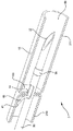
使用する際、針30は(注射器、導入針とカテーテルのアセンブリ、血液採集セットなどにかかわらない)従来の方法で用いられる。導入針とカテーテルのアセンブリ100の場合、針先端32は患者の血管に挿入され、それによってカテーテル108の血管内の位置が定められる。針30は、その後カテーテルを通って引き抜かれて、針シールドアセンブリ5に関して基部の方に移動される。針シールドアセンブリが針に沿って末端へ動くとき、ノッチ42および細長部材40がプレート53の開口14を通り抜ける。細長部材はこのプレートの円筒状の壁によって半径方向内側へノッチ42の内部に向けて付勢される。この場合、プレート53は実質的な干渉がない状態で細長部材を通り過ぎて末端へ移動するようにすることもできる。このプレートが一度細長部材を通過すると、細長部材の自由端41が半径方向外側の位置(すなわち、“非付勢状態”)に戻る。針シールドアセンブリ5は針30に沿って移動し、この移動は針の固定特徴部35がプレート53に接触するまで続けられる。開口14のサイズは、固定特徴部が開口部を通ることができないように定められている。その結果として、針シールドアセンブリ5が針30の先端32から滑り落ちることがなくなる。さらに、細長部材40の自由端41が外側へ付勢されることにより、半径方向においてプレート53の外壁を越えて(特に、開口14を越えて)延在することができる。その結果、針シールドアセンブリ5は針30に沿って基部の方に動いて先端32を再び露出することができなくなる。
In use, the
図3Aおよび3Bに示すように、細長部材40の自由端41は針30から半径方向外側に延びて、軸99からの部材半径もしくは線材半径200を定めている。固定特徴部35は、同様に軸から半径方向外側に延びて特徴部半径201を定めている。プレート53における開口14は軸からの開口半径202を定めている。好ましくは、特徴部半径201はその選択により開口半径202より大きくされて特徴部35が開口14を通り抜けるのを防ぐようにする。開口半径202はその選択により細長部材半径200より小さくされ、針30が針シールドアセンブリ5に関して末端へ移動させられるときに、細長部材40が開口を通り抜けることを防ぐようにしている。細長部材40はその角度が末端方向および外側に向いている。この向きはプレート53の円筒形と協働して、針シールドアセンブリが針に沿って基部の方に移動する場合でも、確実に細長部材の自由端41が開口14を通り抜けないようにすることができる。
As shown in FIGS. 3A and 3B, the
なお、明瞭化のため、開口半径202、特徴部半径201および部材もしくは線材半径200は本発明の他の実施形態を示す図では図示されていない。当然のことながら、図3Aに関して説明したように、他の実施形態におけるプレートの開口14は開口半径202を定め、他の実施形態における(存在する)特徴部35は特徴部半径を定め、また、他の実施形態における細長部材40は部材半径200を定める。
For the sake of clarity, the
図4Aおよび4Bに示される本発明の実施形態を参照すると、プレート53は平らな円板の形状に形成され、この円板は針30の軸99に略垂直であり、一方、シールド本体10がこの円板から末端の方に円筒形状で延在している。この円板の開口14はそのサイズが定められることにより、細長部材40を通すが、針上の固定特徴部35を通さないようにしている。細長部材40がノッチ42と一直線になる(従って、細長部材がプレート53の通路からノッチ内に変位することができる)実施形態では、開口の大きさは針30を通すことができるもので十分である。
Referring to the embodiment of the invention shown in FIGS. 4A and 4B, the
使用に際して、針シールドアセンブリ5は針30に沿い(図4Aと図4Bの比較で)末端の方に移動させられる。プレート53は細長部材40上に乗りそれをノッチ42内に付勢する。プレートを細長部材が完全に通過すると、細長部材はノッチから半径方向外側に曲がり、その自由端41が開口14を越えて半径方向外側に広がる。針シールドアセンブリ5は針30に沿ってさらに末端の方に動かされ、この動きはプレート53が固定特徴部35に接触するまで行われる。プレート53と固定特徴部との干渉のため、針シールドアセンブリ5はそれ以上針30に関して末端の方へ動くことができない。細長部材40とプレート53との干渉によって、針シールドアセンブリ5は針に沿って基部の方へ動くことができない。その結果として、針シールドアセンブリ5は固定特徴部35と細長部材40との間のみを動くことができ、針30の先端32は、その結果として、針シールドアセンブリ5内に閉じ込められることになる。
In use, the
図5A−5Cを参照すると、本発明の実施として、可撓性部材すなわち線材40が針シールドアセンブリ5のシールド本体10に取り付けられたものが示されている。特に、針シールドアセンブリ5には開口14を有したプレート53が含まれる。開口14はそのサイズが定められることにより、針30を受け入れ、針シールドアセンブリ5が針に沿って軸方向にスライドすることが可能となる。シールド本体10はプレート53に取り付けられ、このプレートから末端の方へ延在している。シールド本体は円筒状で、内部室50を形成している。線材40のような可橈性の細長部材はシールド本体に取り付けられて内部室50内に配され、この際、細長部材の自由端41はその内部室内に延びた状態にある。図に示されるように、細長部材は接続点230でシールド本体10の壁を通って延びている。細長部材は様々な方法でシールド本体に取り付けることができ、それらも本発明の実施態様である。例えば、細長部材はシールド本体と一体に形成したり、シールド本体に接着されたり、シールド本体内の内部カラーを用いて摩擦嵌めされたり、シールド本体に溶接されたりすることなどができる。
Referring to FIGS. 5A-5C, the practice of the present invention is shown with a flexible member or
上述したように、細長部材40の自由端41はシールド本体10の中央室50内に延在するものである。シールド本体は、針30上の固定特徴部35を末端方向に通過する際(図5Aと図5Bの比較)、その内部壁に対して細長部材が曲がることができるようにされている。特に、溝153が、シールド本体10の内部壁内の接続点230の近くに配され、そこから基部の方へ延在している。溝は、そのサイズが定められることにより、以下に説明するように、作動する間細長部材を受け入れるものである。溝は、また、中央室の直径が増大し、接続点230から基部の方へ延在する部分とすることもできる。
As described above, the
使用に際して、針シールドアセンブリ5は針30上にスライド可能に装着され、挿入のために針の先端32は露出している。挿入した後、針シールドアセンブリは針に沿って末端の方へ移動する。(当然のことながら、オーバーニードルカテーテルアセンブリ100の場合、通常、針は針シールドアセンブリを通って基部の方へ引き抜かれる。)針上の固定特徴部35は細長部材40の上に乗り上げる。細長部材40は溝153の中にあるので、細長部材が、固定特徴部が針シールドアセンブリを通って基部の方に通過する際にその障害になることはない。針30は針シールドアセンブリを通ってさらに引き抜かれ、この動作は固定特徴部35がプレート53と接触するまで行われる。このプレートの開口14は、そのサイズが定められることにより、固定特徴部がそこを通り抜けることを防止している。この結果、針シールドアセンブリが、針30の先端32から外れることがなくなる。針30が針シールドアセンブリに対して末端の方に移動するときは、先端32は細長部材40と係合して、それを末端の方向でシールド本体10の内部壁154の方に向ける。細長部材40があることによって、固定特徴部35が通過できるスペースが小さくなる。特に、固定特徴部は内部壁154と細長部材40との間で詰まって(図5C参照)、その特徴部が接続点230を通り過ぎることを防止している。結果として、針先端は針シールドアセンブリ5の末端部51から抜け出して元に戻らないようにされている。
In use, the
図6A−6Cを参照すると、本発明の実施として、細長部材が可橈性のリーフスプリング140、141でこれらは針30に装着されて針シールドアセンブリ5が基部および末端の両方向に移動することを制限するものが開示されている。末端側のカラー240は針30に固定して取り付けられている。このカラーは、溶接、接着、摩擦嵌め、またはその他の方法で取り付けることができる。末端側の細長部材140は末端側のカラー240に取り付けられ、基部の方向に延在している。図に示されるように、末端側の細長部材140は末端のカラーと一体に形成されている。細長部材は末端側のカラーに対して接着、溶接または他の方法で取り付けることができる。また、細長部材は針の壁と一体に形成することもできる(この場合、カラーは必要なくなる)。末端側の細長部材は可橈性で針30から半径方向外側に延びている。図に示されるように、末端側の細長部材はリーフスプリングであるが、他の可橈性部材、例えば、線材などを用いることもでき、これらも本発明の実施態様である。
Referring to FIGS. 6A-6C, in accordance with the present invention, the elongated members are
基部側のカラー241は針30に固定して取り付けられ、末端側のカラー240の近くに配置される。末端側のカラーと同じ様に、基部側のカラー241は、溶接、接着、摩擦嵌めあるいは他の方法で取り付けることができる。基部側の細長部材141は基部側のカラーに取り付けられ末端の方向に延びている。図に示されるように、基部側の細長部材141は基部側のカラー241と一体に形成されるが、当然のことながら、基部側の細長部材は基部側のカラーに対して接着、溶接あるいは他の方法で取り付けるようにすることもできる。さらに、基部側の細長部材は針の壁によって一体に形成されてもよい(この場合、カラーは必要なくなる)。末端側の細長部材と同じように、基部側の細長部材は可橈性のもので、針から半径方向外側に延びている。この場合も同様に、基部側の細長部材はリーフスプリングであるが、他の可橈性部材を用いることもでき、それらも本発明の実施態様である。
The
基部側の細長部材141および末端側の自由端341および441互いに近づいているが、好ましくはプレート53の幅よりも大きい距離だけ離されたものである。図に示されるように、細長部材140および細長部材141はそれぞれ一対が存在する。細長部材の数は他のものとすることができ、それらも本発明の実施態様である。基部および末端のカラー241、240は別の構造として示されているが、これらのカラーは一体に形成されて、図6Cに示すように単一の統合カラー400としてもよい。
The proximal
使用に際して、針シールドアセンブリ5は針30にスライド可能に装着されることにより、針の先端32が挿入のために露出することができる。挿入後は、針シールドアセンブリ5は針30に沿って末端の方へ移動し、この移動は針の先端32が針シールドアセンブリ内に入るまで行われる。(当然のことながら、オーバーニードルカテーテル100については、針は通常針シールドアセンブリを通って基部の方へ引き抜かれる。)プレート53の開口14はそのサイズが定められることにより、基部側のカラー214(または統合カラー400の基部側の部分)が通ることができるものである。針シールドアセンブリ5のプレート53は基部側の細長部材141を針の外面に押し付け、その基部側の細長部材がプレートの開口14をスライドして通ることを可能にする。プレートが基部の細長部材の自由端341を通過すると、それらの細長部材はぱっと元に戻り、針本体から半径方向外側に動く。この非付勢状態では、基部側の細長部材141の自由端341が開口14を越えて半径方向に広がる。その際、図6Bに示すように、針シールドアセンブリ5は針30に関して基部の方へ戻る動作をすることができない。これは基部側の細長部材140の自由端341がプレート53と干渉するからである。同様に、針シールドアセンブリ5が針に関してさらに末端の方へ動くことも、末端側の細長部材140の自由端441とプレートとの干渉によって阻止される。この結果として、針シールドアセンブリ5は、針30に関して基部および末端のいずれの方向にも実質的に動くことができなくなる。針先端32は、このようにして針シールドアセンブリ内に入ったままとなる。
In use, the
図7A−7Cを参照すると、本発明の実施は、基部側のシールド本体延長部210を含んだものとして表され、これにより、可橈性の細長部材40が動作状態において一度固定されるとこれに手を伸ばすことができないようにしたものである。特に、針シールドアセンブリ5には開口14を有したプレート53が含まれる。このプレートにシールド本体10の末端側の部分211が取り付けられてそこから末端の方へ延在する。シールド本体の基部側の部分210は上記プレートに取り付けられそこから基部の方へ延在する。細長部材40は針30に対して接続点230で取り付けられ、針から半径方向外側に延びている。固定特徴部35は接続点より末端側に配置される。
Referring to FIGS. 7A-7C, the practice of the present invention is represented as including a
図に描かれるように、シールド本体10の基部側の部分210および末端側の部分211は、プレート53と一体に形成され、このプレートはシールド本体の狭められた部分もしくは波形を付けられた部分である。プレート53は、また、本明細書全体で説明する他の構成を有することもでき、それらも本発明の実施態様である。例えば、プレートは単一の円板または細長い円筒状の開口とすることもできる。さらに、プレートはシールド本体から分離した構造で、動作可能に係合するものとすることができる。シールド本体それ自身は、動作可能に結合する別体の末端部分と基部部分とによって形成してもよい。上述したように、固定特徴部35は末端の細長部材141で置き換えることができる。
As depicted, the
使用に際して、針シールドアセンブリ5は針30にスライド可能に装着されることにより、針の先端32が挿入のために露出する。挿入の後針シールドアセンブリ5は針に沿って末端の方へ移動し、この移動は針の先端32が針シールドアセンブリの中に入るまで行われる。(当然のことながら、オーバーニードルカテーテル100については、針は通常針シールドアセンブリを通って基部の方へ引き抜かれる。)プレート53が細長部材40上を通過するとき、この細長部材はノッチ42内に変位して、プレート53が細長部材の上を末端の方へ通過することを可能にする。プレート53が細長部材を通過すると、細長部材は外側方向にぱっと戻り、(図7Bに示すように)針シールドアセンブリの中央室50内に向かう。上述したように、細長部材は、このようにして針シールドアセンブリ5が針に関して基部の方へ戻ることを防止している。固定特徴部35はそのサイズが定められることにより、プレート53が開口14を通ることができないようにされている。この結果、プレートは固定特徴部と細長部材との間に閉じ込められ、また、針先端32は針シールドアセンブリ5内に閉じ込められる。細長部材40は、また、針シールドアセンブリ5の基部側部分210内に入れられ、プレート53と細長部材との係合を改ざんしようとすることを減じることができる。
In use, the
図8A−8Bを参照すると、本発明の実施として、針シールドアセンブリ5に2つのプレート53、234が用いられて針30が針シールド5に関して軸方向に移動することを制限することが示されている。針シールドアセンブリには基部側の開口14を有した基部側プレート53が含まれる。シールド本体10は基部側プレートに取り付けられ、このプレートから末端側へ延在する。末端側のプレート243はシールド本体10に取り付けられ、シールド本体の中央室内に配される。末端側のプレートには末端側開口214が含まれる。針30は基部側開口14および末端側開口214内に配され、その際に、針シールドアセンブリ5は針に沿ってスライドできるようにされる。
Referring to FIGS. 8A-8B, it can be seen that, as an implementation of the present invention, two
針30には針本体上にまたはその本体とともに形成された固定特徴部35が含まれる。針にはノッチ42が配され、これは固定特徴部35よりも末端側に位置する。線材40のような可橈性の細長部材は針30に対してノッチ42の基部側端に近い接続点230で取り付けられる。細長部材はノッチから末端方向に延び、また、ノッチと一直線となる。固定特徴部の基部側端と細長部材は、以下に説明するように、十分な距離だけ離され、これにより、それらの両方が基部側プレート53と末端側プレート234との間に位置することが可能となる。シールド本体10の部分211は末端側プレート234を越えて延在し、これにより確実に針先端32が動作の後シールド本体10内に含まれるようにしている。
図に示されるように、基部側プレート53は平らな円板であるが、末端側プレート234は基部側を向くじょうご形状を有している。当然のことながら、プレートは他の形状を有していてもよく、それらも本発明の実施態様である。例えば、プレートは円筒形状を有し、また、拡大するカラーなどを備えていてもよい。基部側プレート53に含まれる開口14のサイズが針30それ自身の通過を可能とするものでも、固定特徴部35の通過を阻止するものである。その結果として、針シールドアセンブリ5は針30の先端32から外れることがない。末端側プレート234はその形状およびサイズが定められることにより、針シールド5が針に関して末端の方へ動くときに、固定特徴部35と細長部材40が末端側開口214を通過することを可能とするが、針シールドアセンブリが針に沿って基部側に動いたとしても細長部材が末端側開口214を通過することを防ぐようにすることができる。
As shown in the figure, the
使用に際して、針シールドアセンブリ5は針30上にスライド可能に装着され、この際、針の先端32が挿入のために露出されるようにする。挿入の後は、針シールドアセンブリ5は針30に沿って末端の方へ移動し、この移動は針の先端32が針シールドアセンブリ内に至るまで行われる。(当然のことながら、オーバーニードルカテーテル100については、針は、通常針シールドアセンブリを通って基部側へ引き抜かれる。)固定特徴部35は末端側開口214を通過する。針30がさらに基部側へ移動すると、末端側プレート234が細長部材40をノッチ42内へ押して、その細長部材が末端側開口を通過することができるようにする。じょうご形状の末端側プレートは固定特徴部の通過を案内することや細長部材を押すことの手助けとなる。針30が針シールドアセンブリ5に対してさらに基部側へ移動すると、固定特徴部35が基部側プレート53と接して、針が針シールドアセンブリに対してさらに移動することを防ぐ。針30が針シールドアセンブリ5に関して末端側へ付勢されても、細長部材40が末端側プレート234と接して針先端32が針シールドアセンブリの末端側端部211から再び現れることを防いでいる。
In use, the
図9A−9Cを参照すると、本発明の実施として、固定特徴部35と細長部材40が一体に形成されることを除いて、図8A−8Bの実施と同様のものが示されている。針シールドアセンブリ5には基部側開口14を有した基部側プレート53が含まれる。シールド本体10は基部側プレートに取り付けられるとともに、このプレートから末端側へ延在している。末端側プレート234はシールド本体に対して基部側プレートより末端側の位置で取り付けられる。この末端側プレートは末端側開口の形を定めている。シールド本体10は末端側プレートを越えて末端側へ延在することにより、以下で説明するように、動作状態にあるときにシールド本体の中に針先端32を入れた状態とすることができる。
Referring to FIGS. 9A-9C, the implementation of the present invention is similar to the implementation of FIGS. 8A-8B, except that the securing
特徴部35は針30に取り付けられる。図示されるように、特徴部は、溶接、接着、摩擦嵌めなどによって張りの周りに固定されたフェルールないしその他の環とするものである。細長部材40はフェルールと一体に形成され、このフェルールから末端側へ延びている。細長部材の形状は、それらの自由端141が針の外面から半径方向に離れる方向に広がるものである。例えば、図9Aを参照するとき、針にノッチ42を含めるようにしてもよいが、本発明のこの実施態様には必要ないと考えられるものである。末端側の開口214はそのサイズが定められることにより、フェルールの通過を可能とするとともに、細長部材が針の側部に押圧されているときにはその細長部材の通過も可能とする。基部側プレートにおける基部側開口はそのサイズが定められることにより、固定特徴部の通過を阻止する。
The
使用に際して、針シールドアセンブリ5は針30上にスライド可能に装着されることにより、針の先端32が挿入のために露出することができる。挿入の後、針シールドアセンブリ5は針に沿って末端側へ移動し、この移動を針の先端32が針シールドアセンブリ内に入るまで行われる。(当然のことながら、オーバーニードルカテーテルアセンブリ100については、針は通常針シールドアセンブリを通って基部側へ引き抜かれる。)固定特徴部35は末端側開口214を通過する。針30がさらに基部側へ移動すると、末端側プレート234が細長部材40を針の側部に押し付ける。一度押し付けられると、細長部材は末端側開口を通過することができる。末端側プレートはじょうご形状を具えて、固定特徴部の通過や細長部材の押し付けを導くのに役立つようにしてもよい。針30が針シールドアセンブリ5に関してさらに基部側に移動すると、固定特徴部35は基部側プレート53と接触して針が針シールドアセンブリに関してさらに基部側へ移動することを阻止する。針30が針シールドアセンブリに関して末端側へ付勢されたとしても、図9Cにおいて参照されるように、細長部材40が末端側プレートと係合して針先端32が針シールドアセンブリの末端側端部から再び現れることを防止することができる。
In use, the
図10A−10Bを参照すると、本発明の実施として、弾性部材すなわち細長部材40が針30と一体に形成されることが示されている。当然のことながら、一体の細長部材は本明細書で説明される他の実施物とともに用いることもできる。針シールドアセンブリ5には好ましくは円筒形状のプレート53が含まれる。このプレートにはシールド本体10が取り付けられるとともに、この本体はプレートから末端側へ延在する。針の一部42が切取られることにより、リーフスプリングないし線材40のような細長部材を形成されて、この細長部材は針から半径方向外側に向けて付勢されるものとなる。固定特徴部35は針30上で細長部材40より末端側の位置に配される。プレート53は開口14の形を定めてその形状とサイズをリーフスプリング40を押し付けることができるものとし、これにより、針が針シールドアセンブリに関して基部側へ移動するとき、リーフスプリングが開口14を通過できるようにしている。このリーフスプリングに対する押圧は、プレート53に隣接するシールド本体10のじょうご形状によって促進される。シールド本体はその長さが、針シールドアセンブリ5が、図10Bに示されるように、針の基部側端部で動作状態に移動するとき、針の先端32が針シールドアセンブリ5内に入るのに十分なものである。
Referring to FIGS. 10A-10B, it can be seen that an elastic member or
使用に際して、針シールドアセンブリ5は針30にスライド可能に装着されることによって、針の先端32が挿入のために露出することができる。挿入の後は、針シールドアセンブリ5は針に沿って末端側へ移動し、この移動は針の先端が針シールドアセンブリ内に入るまで行われる。(当然のことながら、オーバーニードルカテーテル100については、針は通常針シールドアセンブリを通って基部側に引き抜かれる。)プレート53が細長部材すなわちリーフスプリング40上をスライドするとき、そのプレートによってリーフスプリングを針30のノッチ42内に押し込む。リーフスプリングを形成することによって針30内にノッチ42を生じさせることから、このノッチが自動的にリーフスプリングと一直線となり、また、変位を受け入れることができる。プレート53が完全にリーフスプリングの上を通過すると、リーフスプリングはその変位前の状態に戻り、半径方向外側に動いて針から離れる(図10B)。それによって、針シールドアセンブリ5が針に対して基部側へ戻り針の先端を露出することを防ぐことができる。これはプレート53がリーフスプリング40に係合して戻る動きを防ぐからである。プレートの開口14はそのサイズが定められることにより、固定特徴部35の通過を阻止している。このようにして、針シールドアセンブリ5が針の先端35から外れないようにしている。
In use, the
図11A−11Bを参照すると、図10A−10Bの実施と同様のものが示されている。針30は小さな直径部分130を具えている。フェルール55が小さな直径部分に取り付けられる。好ましくは、小さい直径部分に取り付けられるとき、フェルール55はその直径が針の他の部分と同じかまたはそれより小さいものである。細長部材40はフェルールと一体に形成され、末端側へ延びている。プレート53には開口14が含まれ、この開口のサイズが定められることによりこの開口を針やフェルールが通過することができる。動作の間、プレート53によって細長部材40が小さな直径部分130の方に曲がり、細長部材40が同様に開口14を通過できるようにしている。細長部材40が一度プレート53を越えて完全に通過すると、細長部材は針の小さな直径部分から半径方向外側に曲がる。その結果、細長部材40の自由端41は開口を通過して戻ることができず、針シールドアセンブリ5が針状に捕えられて、針先端32が再び露出することを防いでいる。
Referring to FIGS. 11A-11B, a similar one to the implementation of FIGS. 10A-10B is shown.
図12A−12Bを参照すると、本発明の実施として、図9A−9Cのものと同じものが示されている。この例における末端側プレート234は、傾くもしくは傾斜するプレートであり、このプレートは基部側出っ張り730と末端側出っ張り740との間の一端で係合している。さらなる末端側出っ張り731が設けられ、針シールドアセンブリ5内の針30を引き抜くときの末端側プレートの傾きを防いでいる。
Referring to FIGS. 12A-12B, an implementation of the invention is shown that is the same as that of FIGS. 9A-9C. The
使用に際して、針シールドアセンブリ5は針30上にスライド可能に装着されることにより、針の先端32が挿入のために露出することができる。挿入の後、針シールドアセンブリ5は針に沿って末端側へ移動し、この移動は針の先端32が針シールドアセンブリ内に入るまで行われる。(当然のことながら、オーバーニードルカテーテルアセンブリ100については、針は通常針シールドアセンブリを通って基部側に引き抜かれる。)固定特徴部34は末端側開口214を通過する。針30がさらに基部側へ移動するとき、末端側プレート234は細長部材40を針の側部に押し付ける。この末端側プレートは出っ張り730、740および731によって傾くことが阻止される。一度押し付けられると、細長部材40は末端側開口214を通過することができる。末端側プレート234はじょうご形状を具えていてもよく、これにより、固定特徴部の通過や細長部材の押し付けを導くことの手助けとなる。針30が針シールドアセンブリに関してさらに基部側へ移動すると、固定特徴部35は基部側プレート53に接触して、針が針シールドアセンブリに関してさらに基部側へ移動しないようにする。針30が針シールドアセンブリ5に関して末端側へ付勢されても、細長部材が末端側プレート234と係合してこのプレートを傾ける。この末端側プレートは、出っ張り730、740によって、針に対して末端側へ移動することが防止される。一端傾くと、末端側プレート234は針の外側で動かなくなり、針が末端側プレートに対してそれ以上動かないようにしている。
In use, the
以上で示された本発明の実施には、プレート53と、このプレートと一体に形成され、また、このプレートから末端側へ延在するシールド本体とが含まれる。当然のことながら、このプレートとシールド本体は別の部材とすることができ、これらは動作可能なように係合することにより、固定特徴部35および細長部材40によるプレート53の移動の制限が針先端32を覆う針シールドアセンブリ5による封じ込めを生じさせるようにすることができる。プレート53それ自身は、それが細長部材40と作用し合って針シールドアセンブリ5の基部側へ戻らないようにする限り、他の形状を有してもよい。例えば、このプレートは円錐形で基部側に向かって狭くなる形状を有することができる。この形状は細長部材40をノッチ42内に案内する手助けとなる。細長部材はノッチと一直線となるものとして表される。細長部材は、ノッチと一直線とならない他の位置で針に取り付けることもできる。このような場合には、プレート53の開口14は、プレートが細長部材上を末端側へ動かされるときに細長部材と針を中に入れる必要があるが、この場合でも、固定特徴部の通過を阻止するのに足りるほど小さいものである。また、開口はそのサイズが十分に小さく定められることにより、細長部材の自由端41がその広がった状態で通過することができないようにする必要がある。
The implementation of the present invention shown above includes a
図に示したように、1つまたは2つの細長部材40が用いられてプレート53と係合する。当然のことながら、細長部材の数は特定の目的に応じて他の数でもよく、それらの本発明の実施態様である。さらに、細長部材40を、針30に対してシールド5が移動することを制限するのに用いることができることは明らかである。シールドはその長さを適切なものとして、その制限の際に、針の先端32がシールドから現れないようにすることを確実にする必要がある。このことは、ある実施では、シールドの、プレートより末端側の部分が、接続点230と針先端との間の距離より長いことを確保することによって達成できる。
As shown, one or two
上述されたように、固定特徴部35は針シールドアセンブリ5が針30の先端32から外れるのを防ぐのに用いられる。当然のことながら、つなぎ綱や傾いた板などの他の機構を用いて針シールドアセンブリが針先端から外れることを防いでもよく、それらも本発明の実施態様である。
As described above, the locking
当然のことながら、上述した本発明の実施の要素は組み合わせてもよく、それらも本発明の実施態様である。上記の説明は本発明を制限するものと解されてはならず、本発明は特許請求の範囲によって明らかとなるものである。 It will be appreciated that the above-described elements of the present invention may be combined and are also embodiments of the present invention. The above description should not be construed as limiting the invention, which is apparent from the claims.
Claims (31)
本体および先端を有した針カニューレ(30)であって、前記先端が前記カニューレの末端(130)に配された針カニューレ(30)と、
前記針カニューレにスライド可能に装着されて基部側位置から末端側位置へ動くことができるシールド(5)であって、中央室(50)を有したシールド本体(10)を備えたシールド(5)と、
カテーテルアダプタ(8)を有したカテーテル(108)であって、前記針カニューレの先端(32)がカテーテルの末端から外へ抜け出て延在するよう針カニューレを覆うように位置したカテーテル(108)と、
を具え、
前記シールド(5)が基部側位置から末端側位置へ動くときに部材(40、140、141)が変位して前記シールドの末端側位置から基部側位置への動きを止め、
前記部材が、前記針カニューレ(30)に接続点で固定して取り付けられる細長部材(40、140、141)であって、前記細長部材(40、140、141)が前記針カニューレから離れた非付勢状態から前記針カニューレに近い付勢状態に移ることが可能であることを特徴とする医療用針アセンブリ。In the medical needle assembly,
A needle cannula (30) having a body and a tip, the needle cannula the tip was arranged at the end (130) of said cannula (30),
A shield (5) slidably mounted on said needle cannula and capable of moving from a proximal position to a distal position, comprising a shield body (10) having a central chamber (50) When,
A catheter (108) with a catheter adapter (8), wherein the needle cannula tip (32) is positioned to cover the needle cannula so that it extends out of the distal end of the catheter; ,
With
When the shield (5) moves from the base position to the distal position, the members (40, 140, 141) are displaced to stop the movement of the shield from the distal position to the base position,
The member is an elongated member (40, 140, 141) fixedly attached to the needle cannula (30) at a connection point, wherein the elongated member (40, 140, 141) is separated from the needle cannula. A medical needle assembly capable of moving from a biased state to a biased state close to the needle cannula.
前記基部側フェルール(241)と前記先端(32)との間で前記針カニューレ(30)に取り付けられる末端側フェルール(240)と、該末端側フェルールに取り付けられるとともに、前記末端側フェルールから基部側に向けて延在する末端側細長部材(140)とをさらに具えたことを特徴とする請求項1に記載の医療用針アセンブリ。A base-side ferrule (241) attached to the needle cannula (30) , the elongated member (141) being attached to the base-side ferrule and extending from the base-side ferrule to the distal side;
Wherein the needle cannula distal ferrule attached to the (30) (240) in between said tip (32) and the proximal ferrule (241), together with the attached to said distal end ferrule, proximal from the distal ferrule The medical needle assembly of claim 1, further comprising a distal elongate member (140) extending toward the distal end.
前記シールドが前記基部側位置から前記末端側位置へ動かされるとき、前記プレートは前記細長部材(40)の前記第2端部を前記針カニューレの近くに移動させて、前記細長部材が前記開口(14)を通ることができるようにすることを特徴とする請求項1乃至12のいずれかに記載の医療用針アセンブリ。Fixed to said shield body (10), comprising a plate which defines an opening (14) (53),
When the shield is moved from the proximal position to the distal position, the plate moves the second end of the elongate member (40) closer to the needle cannula so that the elongate member is in the opening ( 14. The medical needle assembly according to any one of claims 1 to 12, wherein the medical needle assembly is capable of passing through 14) .
前記フェルールに取り付けられ、前記針本体から半径方向外側に延びる自由端(441)を有した細長部材であって、前記自由端が部材半径を規定する細長部材(140)と、を具え、
前記シールド(5)が、前記シールド本体の前記基部側端に固定され、厚みを有し開口半径を持った開口(14)を定めたプレート(53)を備え、
前記シールド(5)が前記基部側位置にあるとき、前記針(30)は少なくとも部分的に前記中央室内に配され、前記針は前記プレートの前記開口(14)を通って延在し、および
前記開口半径は前記部材半径より小さいことを特徴とする請求項1に記載の医療用針アセンブリ。 Ferrules (240, 241) attached to the needle body at a position close to the tip (32) ;
Attached to said ferrule, said from the needle body an elongate member having a free end (441) extending radially outwardly, comprises a, an elongated member (140) in which the free end defines a member radius,
The shield (5) includes a plate (53) that is fixed to the base side end of the shield body and has an opening (14) having a thickness and an opening radius;
When the shield (5) is in the proximal position, the needle (30) is at least partially disposed in the central chamber, the needle extends through the opening (14) in the plate, and The medical needle assembly of claim 1, wherein the opening radius is smaller than the member radius.
前記基部側フェルール(241)より末端側で前記針本体に取り付けられた末端側フェルール(240)と、
前記末端側フェルールに取り付けられ、基部側の方向に延在する末端側細長部材(140)であって、前記末端側細長部材には前記針本体から外側に第2部材半径まで付勢される第2自由端(441)が含まれた末端側細長部材(140)と、
をさらに具え、
前記開口半径(14)は前記第2部材半径より小さいことを特徴とする請求項23に記載の医療用針アセンブリ。The ferrule is a base side ferrule (241) , the elongated member (141) is a base side elongated member,
The proximal ferrule (241) distal ferrule attached to the needle body at a more distal side (240),
A distal elongated member (140) attached to the distal ferrule and extending in a proximal direction, wherein the distal elongated member is biased outwardly from the needle body to a second member radius. A distal elongate member (140) including two free ends (441) ;
Further comprising
24. The medical needle assembly of claim 23 , wherein the opening radius (14) is smaller than the second member radius.
前記シールド本体に前記基部側プレート(53)より末端側で固定され、末端側開口(214)を定める末端側プレート(234)と、
を備え、
前記シールド(5)が前記基部側位置にあるとき、前記針(30)が少なくとも部分的に前記中央室内(50)にあり、前記針が前記基部側開口(14)および前記末端側開口(214)を通って延在し、および
前記末端側開口(214)は前記細長部材(40)が基部側の方向に通過することをできるようにしたものであり、また、前記細長部材が末端側方向に通過することを阻止することを特徴とする請求項1に記載の医療用針アセンブリ。A base plate (53) fixed to the base side end of the shield body and defining a base side opening (14) ;
A distal plate (234) fixed to the shield body on the distal side from the base plate (53 ) and defining a distal opening (214) ;
With
When the shield (5) is in the proximal position, the needle (30) is at least partially in the central chamber (50) and the needle is in the proximal opening (14) and the distal opening (214 And the distal opening (214) allows the elongate member (40) to pass in a proximal direction, and the elongate member is in the distal direction. The medical needle assembly according to claim 1, wherein the medical needle assembly is prevented from passing through the medical needle assembly.
Applications Claiming Priority (3)
| Application Number | Priority Date | Filing Date | Title |
|---|---|---|---|
| US39049902P | 2002-06-20 | 2002-06-20 | |
| US10/320,960 US6652490B2 (en) | 1998-04-09 | 2002-12-17 | Catheter and introducer needle assembly with compact needle shield |
| PCT/US2003/019666 WO2004007013A1 (en) | 2002-06-20 | 2003-06-20 | Method and apparatus for shielding the tip of a catheter introducer needle |
Publications (3)
| Publication Number | Publication Date |
|---|---|
| JP2005529719A JP2005529719A (en) | 2005-10-06 |
| JP2005529719A5 JP2005529719A5 (en) | 2006-08-10 |
| JP4476120B2 true JP4476120B2 (en) | 2010-06-09 |
Family
ID=30002830
Family Applications (1)
| Application Number | Title | Priority Date | Filing Date |
|---|---|---|---|
| JP2004521478A Expired - Lifetime JP4476120B2 (en) | 2002-06-20 | 2003-06-20 | Method and apparatus for shielding the tip of a catheter introducer needle |
Country Status (10)
| Country | Link |
|---|---|
| US (1) | US7507222B2 (en) |
| EP (5) | EP3175880B1 (en) |
| JP (1) | JP4476120B2 (en) |
| CN (3) | CN101543657B (en) |
| AT (1) | ATE416000T1 (en) |
| AU (1) | AU2003245632A1 (en) |
| BR (1) | BR0311907B1 (en) |
| DE (1) | DE60325052D1 (en) |
| ES (1) | ES2318143T3 (en) |
| WO (1) | WO2004007013A1 (en) |
Families Citing this family (73)
| Publication number | Priority date | Publication date | Assignee | Title |
|---|---|---|---|---|
| EP3381495B1 (en) * | 2003-03-25 | 2020-07-15 | Becton, Dickinson and Company | Iv catheter and needle assembly and method |
| CA2550114C (en) * | 2005-06-20 | 2013-11-19 | Sherwood Services, Ag | Safety shield for medical needles |
| ATE424879T1 (en) | 2005-07-06 | 2009-03-15 | Vascular Pathways Inc | INTRAVENOUS CATHETER INSERTION DEVICE AND METHOD OF USE |
| US8235945B2 (en) * | 2006-06-08 | 2012-08-07 | Rishi Baid | Safety device to cover the needle tip of intravenous catheter apparatus |
| US9358348B2 (en) * | 2006-06-14 | 2016-06-07 | Covidien Lp | Safety shield for medical needles |
| CN101112639B (en) * | 2006-07-27 | 2012-07-18 | 贝克顿·迪金森公司 | Vessel having a safeguard device and introducing needle component |
| US8382718B2 (en) * | 2006-07-31 | 2013-02-26 | B. Braun Melsungen Ag | Needle assembly and components thereof |
| JP4994775B2 (en) | 2006-10-12 | 2012-08-08 | 日本コヴィディエン株式会社 | Needle point protector |
| US9056188B2 (en) * | 2006-11-22 | 2015-06-16 | Becton, Dickinson And Company | Needle shielding flag structures |
| US9220871B2 (en) * | 2006-11-22 | 2015-12-29 | Becton, Dickinson And Company | Needle shielding pawl structures |
| US7871397B2 (en) * | 2006-12-26 | 2011-01-18 | Stat Medical Devices, Inc. | Pen needle tip |
| DE602008003791D1 (en) | 2007-05-07 | 2011-01-13 | Vascular Pathways Inc | INTRODUCTION OF INTRAVENOUS CATHETER AND BLOOD DETECTING DEVICE AND METHOD OF USE |
| US7713243B2 (en) * | 2007-09-25 | 2010-05-11 | Becton, Dickinson And Company | Tip shield for needle stick prevention |
| US8496623B2 (en) * | 2009-03-02 | 2013-07-30 | Becton, Dickinson And Company | Bi-directional cannula feature capture mechanism |
| US8439877B2 (en) * | 2009-03-02 | 2013-05-14 | Becton, Dickinson And Company | Bi-directionally engageable cannula crimp feature |
| US9399120B2 (en) | 2009-03-02 | 2016-07-26 | Becton, Dickinson And Company | Bi-directional cannula feature capture mechanism |
| US8936575B2 (en) † | 2009-03-19 | 2015-01-20 | Becton, Dickinson And Company | Cannula-tip shielding mechanism |
| US20110023281A1 (en) * | 2009-04-30 | 2011-02-03 | Stat Medical Devices, Inc. | Pen injection device cap with integral pen needle quick release and/or removal system |
| US9700681B2 (en) * | 2009-05-15 | 2017-07-11 | Stat Medical Devices, Inc. | Pen needle with quick release and/or removal system |
| US20100305519A1 (en) * | 2009-06-02 | 2010-12-02 | Becton, Dickinson And Company | Cannula having an overlapping cannula feature and notch feature |
| DE202009009119U1 (en) | 2009-07-02 | 2009-12-31 | B. Braun Melsungen Ag | Protection device for a hypodermic needle |
| US8474300B2 (en) * | 2009-07-20 | 2013-07-02 | Becton, Dickinson And Company | Methods to provide a feature on a needle |
| US8323249B2 (en) | 2009-08-14 | 2012-12-04 | The Regents Of The University Of Michigan | Integrated vascular delivery system |
| US20110060292A1 (en) * | 2009-08-14 | 2011-03-10 | Stat Medical Devices, Inc. | Pen needle storage device with integral removal and/or installation system |
| US8216186B2 (en) * | 2010-03-10 | 2012-07-10 | Becton, Dickinson And Company | Catheter device with hooding feature |
| US9872971B2 (en) | 2010-05-14 | 2018-01-23 | C. R. Bard, Inc. | Guidewire extension system for a catheter placement device |
| US11925779B2 (en) | 2010-05-14 | 2024-03-12 | C. R. Bard, Inc. | Catheter insertion device including top-mounted advancement components |
| US9950139B2 (en) | 2010-05-14 | 2018-04-24 | C. R. Bard, Inc. | Catheter placement device including guidewire and catheter control elements |
| US8932258B2 (en) | 2010-05-14 | 2015-01-13 | C. R. Bard, Inc. | Catheter placement device and method |
| US10384039B2 (en) | 2010-05-14 | 2019-08-20 | C. R. Bard, Inc. | Catheter insertion device including top-mounted advancement components |
| US8814833B2 (en) | 2010-05-19 | 2014-08-26 | Tangent Medical Technologies Llc | Safety needle system operable with a medical device |
| WO2011146769A2 (en) | 2010-05-19 | 2011-11-24 | Tangent Medical Technologies Llc | Integrated vascular delivery system |
| US8257322B2 (en) | 2010-06-02 | 2012-09-04 | Smiths Medical Asd, Inc. | Tip protector for a safety catheter |
| US8932259B2 (en) * | 2010-09-13 | 2015-01-13 | Becton, Dickinson And Company | Catheter assembly |
| US10463803B2 (en) | 2010-11-12 | 2019-11-05 | Stat Medical Devices, Inc. | Pen needle with quick release and/or removal system |
| US8690833B2 (en) | 2011-01-31 | 2014-04-08 | Vascular Pathways, Inc. | Intravenous catheter and insertion device with reduced blood spatter |
| US8961470B2 (en) | 2011-02-17 | 2015-02-24 | Steven Schraga | Pen needle with safety shield system |
| EP3563898B1 (en) | 2011-02-25 | 2020-11-11 | C.R. Bard, Inc. | Medical component insertion device including a retractable needle |
| US8764711B2 (en) | 2011-02-28 | 2014-07-01 | Injectimed, Inc. | Needle guard |
| US9238104B2 (en) | 2011-02-28 | 2016-01-19 | Injectimed, Inc. | Needle guard |
| EP3785653A1 (en) | 2011-04-12 | 2021-03-03 | Thermedical, Inc. | Devices for remote temperature monitoring in fluid enhanced ablation therapy |
| US8486024B2 (en) | 2011-04-27 | 2013-07-16 | Covidien Lp | Safety IV catheter assemblies |
| USD903101S1 (en) | 2011-05-13 | 2020-11-24 | C. R. Bard, Inc. | Catheter |
| WO2013048768A1 (en) | 2011-09-26 | 2013-04-04 | Covidien Lp | Safety iv catheter and needle assembly |
| EP2760520A1 (en) | 2011-09-26 | 2014-08-06 | Covidien LP | Safety catheter |
| US8834422B2 (en) | 2011-10-14 | 2014-09-16 | Covidien Lp | Vascular access assembly and safety device |
| US9078978B2 (en) | 2011-12-28 | 2015-07-14 | Stat Medical Devices, Inc. | Needle assembly with safety system for a syringe or fluid sampling device and method of making and using the same |
| US9522254B2 (en) | 2013-01-30 | 2016-12-20 | Vascular Pathways, Inc. | Systems and methods for venipuncture and catheter placement |
| US9592367B2 (en) * | 2013-07-30 | 2017-03-14 | Becton, Dickinson And Company | Blood control catheter valve employing actuator with flexible retention arms |
| GB2508466C (en) | 2013-08-21 | 2017-11-08 | Braun Melsungen Ag | Catheter Assembly |
| CN104740716B (en) * | 2013-12-27 | 2017-08-01 | 苏州和林微纳科技有限公司 | A kind of anti-error thorn anti-blood polluting device of remaining needle |
| EP3102258A4 (en) | 2014-02-04 | 2017-12-27 | ICU Medical, Inc. | Self-priming systems and methods |
| US9555221B2 (en) | 2014-04-10 | 2017-01-31 | Smiths Medical Asd, Inc. | Constant force hold tip protector for a safety catheter |
| US10118000B2 (en) | 2014-04-21 | 2018-11-06 | Stat Medical Devices, Inc. | Pen needle installation and removal safety cover and pen needle assembly utilizing the same |
| US10155091B2 (en) | 2014-07-11 | 2018-12-18 | Stat Medical Devices, Inc. | Pen needle tip and method of making and using the same |
| WO2016037127A1 (en) | 2014-09-05 | 2016-03-10 | C.R. Bard, Inc. | Catheter insertion device including retractable needle |
| WO2016123616A1 (en) | 2015-01-30 | 2016-08-04 | Smiths Medical Asd, Inc. | Intravenous catheter assembly design |
| WO2016123612A1 (en) | 2015-01-30 | 2016-08-04 | Smiths Medical Asd, Inc. | Releaseable catheter hub retainer |
| WO2016156024A1 (en) * | 2015-04-01 | 2016-10-06 | Novo Nordisk A/S | Electroformed needle cannula |
| USD903100S1 (en) | 2015-05-01 | 2020-11-24 | C. R. Bard, Inc. | Catheter placement device |
| WO2016187037A1 (en) | 2015-05-15 | 2016-11-24 | C.R.Bard, Inc. | Catheter placement device including an extensible needle safety component |
| WO2017151052A1 (en) * | 2016-03-04 | 2017-09-08 | Vigmed Ab | Blood collection device |
| US11344220B2 (en) | 2016-05-13 | 2022-05-31 | Becton, Dickinson And Company | Invasive medical device cover with magnet |
| US9743984B1 (en) | 2016-08-11 | 2017-08-29 | Thermedical, Inc. | Devices and methods for delivering fluid to tissue during ablation therapy |
| US10032552B2 (en) * | 2016-08-30 | 2018-07-24 | Becton, Dickinson And Company | Cover for tissue penetrating device with integrated magnets and magnetic shielding |
| JP7051821B2 (en) | 2016-09-12 | 2022-04-11 | シー・アール・バード・インコーポレーテッド | Blood control for catheter insertion device |
| JP6953541B2 (en) | 2017-03-01 | 2021-10-27 | シー・アール・バード・インコーポレーテッドC R Bard Incorporated | Catheter insertion device |
| WO2019173641A1 (en) | 2018-03-07 | 2019-09-12 | Bard Access Systems, Inc. | Guidewire advancement and blood flashback systems for a medical device insertion system |
| US11083871B2 (en) | 2018-05-03 | 2021-08-10 | Thermedical, Inc. | Selectively deployable catheter ablation devices |
| US11918277B2 (en) | 2018-07-16 | 2024-03-05 | Thermedical, Inc. | Inferred maximum temperature monitoring for irrigated ablation therapy |
| USD921884S1 (en) | 2018-07-27 | 2021-06-08 | Bard Access Systems, Inc. | Catheter insertion device |
| US11642833B2 (en) * | 2018-09-25 | 2023-05-09 | Smiths Medical Asd, Inc. | Cannula bump |
| EP4010057A4 (en) | 2019-08-19 | 2023-10-18 | Becton, Dickinson and Company | Midline catheter placement device |
Family Cites Families (76)
| Publication number | Priority date | Publication date | Assignee | Title |
|---|---|---|---|---|
| US4654034A (en) | 1986-02-03 | 1987-03-31 | Masters Edwin J | Safety needle cap |
| US4755170A (en) | 1986-12-03 | 1988-07-05 | Golden Theodore A | Venipuncture and cutaneous sealing device and method |
| US4846811A (en) | 1987-01-29 | 1989-07-11 | International Medical Innovators, Inc. | Sliding sheath for medical needles |
| US4832696A (en) | 1987-03-05 | 1989-05-23 | Luther Medical Products, Inc. | Assembly of needle and protector |
| US4799495A (en) * | 1987-03-20 | 1989-01-24 | National Standard Company | Localization needle assembly |
| US4816024A (en) | 1987-04-13 | 1989-03-28 | Icu Medical, Inc. | Medical device |
| US4944725A (en) | 1987-06-01 | 1990-07-31 | Mcdonald Michael | Safety needle apparatus |
| US4834718A (en) | 1987-06-01 | 1989-05-30 | Michael McDonald | Safety needle apparatus |
| US4952207A (en) * | 1988-07-11 | 1990-08-28 | Critikon, Inc. | I.V. catheter with self-locating needle guard |
| USRE34416E (en) * | 1988-07-11 | 1993-10-19 | Critikon, Inc. | I.V. catheter with self-locating needle guard |
| US4929241A (en) | 1988-08-05 | 1990-05-29 | Kulli John C | Medical needle puncture guard |
| US4978344A (en) | 1988-08-11 | 1990-12-18 | Dombrowski Mitchell P | Needle and catheter assembly |
| US4964854A (en) | 1989-01-23 | 1990-10-23 | Luther Medical Products, Inc. | Intravascular catheter assembly incorporating needle tip shielding cap |
| US5662610A (en) | 1989-02-01 | 1997-09-02 | Sircom; Richard C. | Automatic needle guard tip protection |
| US5458658A (en) | 1989-02-01 | 1995-10-17 | Sero-Guard Corporation | Positive locking needle-mounted needle guard for needle supported catheters |
| CA2045691C (en) | 1989-02-01 | 2005-09-27 | Richard C. Sircom | Disposable automatic hypodermic needle guard |
| US4917669A (en) | 1989-02-08 | 1990-04-17 | Safetyject | Catheter inserter |
| US5135504A (en) | 1989-07-17 | 1992-08-04 | Mclees Donald J | Needle tip guard |
| US5049136A (en) | 1990-01-10 | 1991-09-17 | Johnson Gerald W | Hypodermic needle with protective sheath |
| US5147327A (en) | 1990-01-10 | 1992-09-15 | Johnson Gerald W | Hypodermic needle with protective sheath |
| US5053017A (en) | 1990-02-28 | 1991-10-01 | Chamuel Steven R | Hypodermic needle safety clip |
| US5084023A (en) * | 1990-03-22 | 1992-01-28 | Critikon, Inc. | Bloodless catheter with self-shielding needle |
| US5558651A (en) | 1990-04-20 | 1996-09-24 | Becton Dickinson And Company | Apparatus and method for a needle tip cover |
| US5120321A (en) * | 1990-06-19 | 1992-06-09 | Oksman Henry C | Safety disposable needle |
| US5279591A (en) | 1990-07-16 | 1994-01-18 | Simon Alexander Z | Protector for needle catheter |
| US5051109A (en) | 1990-07-16 | 1991-09-24 | Simon Alexander Z | Protector for catheter needle |
| US5030212A (en) * | 1990-07-30 | 1991-07-09 | Rose Peter J | Puncture guard for needle administration set |
| US5085648A (en) | 1990-09-13 | 1992-02-04 | Becton Dickinson And Company | Dual diameter needle with a smooth transition |
| US5176655A (en) | 1990-11-08 | 1993-01-05 | Mbo Laboratories, Inc. | Disposable medical needle and catheter placement assembly having full safety enclosure means |
| US5186712A (en) | 1991-08-23 | 1993-02-16 | Kansas Creative Devices, Inc. | Intravenous catheter launching device |
| US5195983A (en) | 1991-08-27 | 1993-03-23 | Penta Associates | Syringe guard and disposal system |
| GB9120416D0 (en) | 1991-09-25 | 1991-11-06 | Sterimatic Holdings Ltd | Catheter placement units |
| US5312359A (en) | 1991-12-03 | 1994-05-17 | Wallace Henry G | Intravenous cannula insertion assembly with protective shield |
| US5613952A (en) | 1991-12-23 | 1997-03-25 | Syringe Develpoment Partners | Safety syringe |
| US5215528C1 (en) * | 1992-02-07 | 2001-09-11 | Becton Dickinson Co | Catheter introducer assembly including needle tip shield |
| US5215525A (en) | 1992-09-29 | 1993-06-01 | Sturman Warren M | Safety casing for intravenous catheter needle |
| US5704919A (en) | 1992-12-04 | 1998-01-06 | Travenol Laboratories (Israel) Ltd. | Intravenous cannula assembly |
| US5314503A (en) * | 1993-03-23 | 1994-05-24 | Rasor Associates, Inc. | Automatic sheath protection of hypodermic needle |
| US5300045A (en) | 1993-04-14 | 1994-04-05 | Plassche Jr Walter M | Interventional needle having an automatically capping stylet |
| JP3198492B2 (en) * | 1993-06-18 | 2001-08-13 | ニプロ株式会社 | Indwelling needle with wing |
| US5697907A (en) | 1993-07-20 | 1997-12-16 | Graphic Controls Corporation | Safety catheter |
| US5584809A (en) | 1993-07-20 | 1996-12-17 | Graphic Controls Corporation | Safety catheter |
| US5409461A (en) | 1993-09-28 | 1995-04-25 | Becton Dickinson And Company | Catheter introducer assembly with needle shielding device |
| US5573510A (en) | 1994-02-28 | 1996-11-12 | Isaacson; Dennis R. | Safety intravenous catheter assembly with automatically retractable needle |
| AU654464B3 (en) | 1994-04-20 | 1994-11-03 | Noble House Group Pty Ltd | Protective sheath |
| GB2292525B (en) | 1994-08-24 | 1998-07-01 | Sterimatic Holdings Ltd | Catheter placement units |
| CA2168615A1 (en) | 1995-03-07 | 1996-09-08 | Timothy J. Erskine | Catheter-advancement actuated needle retraction system |
| US6012213A (en) | 1995-06-07 | 2000-01-11 | Chang; Joseph J. | Method for forming a rib on a cannula for a tip protection device |
| US5599310A (en) | 1995-06-07 | 1997-02-04 | Johnson & Johnson Medical, Inc. | I.V. catheter assembly with automatic cannula tip guard |
| US5882337A (en) | 1995-06-07 | 1999-03-16 | Johnson & Johnson Medical, Inc. | Tip protection device |
| US5853393A (en) | 1995-06-07 | 1998-12-29 | Johnson & Johnson Medical, Inc. | Catheter needle locking and catheter hub unlocking mechanism |
| US5713876A (en) | 1995-06-07 | 1998-02-03 | Johnson & Johnson Medical, Inc. | Catheter release mechanism |
| IL118551A (en) | 1995-06-07 | 2004-05-12 | Johnson & Johnson Medical | Protective needle cover containment |
| US5584810A (en) | 1995-07-11 | 1996-12-17 | Becton Dickinson And Company | Needle point guard assembly |
| DE69618405T2 (en) | 1995-09-18 | 2002-08-01 | Becton Dickinson Co | Needle protection with collapsing cover |
| US5879337A (en) | 1997-02-27 | 1999-03-09 | Injectimed, Inc. | Needle tip guard for hypodermic needles |
| GB9605206D0 (en) | 1996-03-12 | 1996-05-15 | Boc Group Plc | Medical devices |
| US5865806A (en) | 1996-04-04 | 1999-02-02 | Becton Dickinson And Company | One step catheter advancement automatic needle retraction system |
| IN189105B (en) * | 1996-05-03 | 2002-12-21 | Nordway Ltd | |
| US5685855A (en) * | 1996-07-23 | 1997-11-11 | Erskine; Timothy J. | Protected needle catheter placement device with sampling provisions and method for its use |
| SE507732C2 (en) | 1996-11-04 | 1998-07-06 | Hydracine Develop Ab | Infusion cannula with needle guard |
| US5772636A (en) * | 1996-12-02 | 1998-06-30 | Becton Dickinson And Company | Catheter assembly with interlocking telescoping needle shield |
| GB9708569D0 (en) | 1997-04-29 | 1997-06-18 | Smiths Industries Ltd | Catheter and needle assemblies |
| US6117108A (en) * | 1997-08-20 | 2000-09-12 | Braun Melsungen Ag | Spring clip safety IV catheter |
| US6379333B1 (en) * | 1998-04-09 | 2002-04-30 | Becton, Dickinson And Company | Catheter and introducer needle assembly with needle shield |
| GB9823598D0 (en) | 1998-10-29 | 1998-12-23 | Smiths Industries Plc | Needle protection devices and assemblies |
| US6280419B1 (en) | 1999-08-09 | 2001-08-28 | Arrow International, Inc. | Hypodermic needle guard |
| WO2001023028A1 (en) * | 1999-09-24 | 2001-04-05 | Becton, Dickinson And Company | Catheter and dual feature introducer needle assembly with needle shield |
| US6224569B1 (en) * | 1999-09-24 | 2001-05-01 | Becton, Dickinson And Company | Compact needle point shield |
| WO2001078595A1 (en) * | 2000-04-18 | 2001-10-25 | Mdc Investment Holdings, Inc. | Medical device with shield having a retractable needle |
| EP1292355B1 (en) | 2000-06-09 | 2007-05-16 | Becton, Dickinson and Company | Catheter and introducer needle assembly with needle shield |
| JP2002058746A (en) * | 2000-08-17 | 2002-02-26 | Terumo Corp | Indwelling needle assembly |
| EP1344544A4 (en) | 2000-12-18 | 2008-09-03 | Terumo Corp | Protector and storage needle assembly |
| CA2477956A1 (en) | 2002-03-14 | 2003-09-18 | Katsuto Nakatsuka | Coated powder, coating composition, and coated article |
| AU2003284115A1 (en) * | 2002-10-10 | 2004-05-04 | Becton, Dickinson And Company | Method of delivering local anesthesia |
| US7798994B2 (en) * | 2005-11-15 | 2010-09-21 | Becton, Dickinson And Company | Needle shield to septum interconnect |
-
2003
- 2003-06-20 EP EP16187759.2A patent/EP3175880B1/en not_active Expired - Lifetime
- 2003-06-20 ES ES03739259T patent/ES2318143T3/en not_active Expired - Lifetime
- 2003-06-20 CN CN2009101298962A patent/CN101543657B/en not_active Expired - Lifetime
- 2003-06-20 CN CNB038143860A patent/CN100553708C/en not_active Expired - Lifetime
- 2003-06-20 DE DE60325052T patent/DE60325052D1/en not_active Expired - Lifetime
- 2003-06-20 AU AU2003245632A patent/AU2003245632A1/en not_active Abandoned
- 2003-06-20 WO PCT/US2003/019666 patent/WO2004007013A1/en active Application Filing
- 2003-06-20 EP EP10179388.3A patent/EP2298404B1/en not_active Expired - Lifetime
- 2003-06-20 CN CN2009101602981A patent/CN101623533B/en not_active Expired - Lifetime
- 2003-06-20 BR BRPI0311907-6A patent/BR0311907B1/en active IP Right Grant
- 2003-06-20 US US10/477,348 patent/US7507222B2/en not_active Expired - Lifetime
- 2003-06-20 JP JP2004521478A patent/JP4476120B2/en not_active Expired - Lifetime
- 2003-06-20 EP EP08167647.0A patent/EP2014328B1/en not_active Expired - Lifetime
- 2003-06-20 EP EP10179409.7A patent/EP2298405B1/en not_active Expired - Lifetime
- 2003-06-20 EP EP03739259A patent/EP1513578B1/en not_active Expired - Lifetime
- 2003-06-20 AT AT03739259T patent/ATE416000T1/en not_active IP Right Cessation
Also Published As
| Publication number | Publication date |
|---|---|
| CN101623533A (en) | 2010-01-13 |
| US7507222B2 (en) | 2009-03-24 |
| US20050080378A1 (en) | 2005-04-14 |
| EP1513578B1 (en) | 2008-12-03 |
| DE60325052D1 (en) | 2009-01-15 |
| EP2298404A1 (en) | 2011-03-23 |
| ATE416000T1 (en) | 2008-12-15 |
| EP3175880A1 (en) | 2017-06-07 |
| WO2004007013A1 (en) | 2004-01-22 |
| CN1662274A (en) | 2005-08-31 |
| EP1513578A1 (en) | 2005-03-16 |
| CN101543657A (en) | 2009-09-30 |
| ES2318143T3 (en) | 2009-05-01 |
| CN101543657B (en) | 2013-05-08 |
| JP2005529719A (en) | 2005-10-06 |
| EP2298405B1 (en) | 2020-05-27 |
| EP2014328A1 (en) | 2009-01-14 |
| EP2298404B1 (en) | 2016-08-10 |
| EP2014328B1 (en) | 2016-10-19 |
| EP2298405A1 (en) | 2011-03-23 |
| CN100553708C (en) | 2009-10-28 |
| CN101623533B (en) | 2013-05-01 |
| BR0311907B1 (en) | 2012-08-21 |
| EP3175880B1 (en) | 2018-08-15 |
| AU2003245632A1 (en) | 2004-02-02 |
| BR0311907A (en) | 2005-04-05 |
Similar Documents
| Publication | Publication Date | Title |
|---|---|---|
| JP4476120B2 (en) | Method and apparatus for shielding the tip of a catheter introducer needle | |
| EP1819385B1 (en) | Needle capture mechanisms | |
| EP2051767B1 (en) | Needle tip protector housing positioned inside a catheter hub | |
| US6224569B1 (en) | Compact needle point shield | |
| JP4333363B2 (en) | Blood collection assembly | |
| JP5638520B2 (en) | Needle shield with telescopic connection | |
| JP4464124B2 (en) | Round forward wing set with shield driven by leaf spring | |
| US20050251092A1 (en) | Needle assembly with tether | |
| EP1248658A2 (en) | Compact needle shielding device | |
| CA2520353C (en) | Safety needle and catheter assembly | |
| EP1338299A1 (en) | Compact needle shielding device | |
| AU783791B2 (en) | Compact needle shielding device | |
| JP2003250903A (en) | Compact needle shielding device | |
| MXPA06005796A (en) | Resettable safety shield for medical needles |
Legal Events
| Date | Code | Title | Description |
|---|---|---|---|
| A521 | Request for written amendment filed |
Free format text: JAPANESE INTERMEDIATE CODE: A523 Effective date: 20060620 |
|
| A621 | Written request for application examination |
Free format text: JAPANESE INTERMEDIATE CODE: A621 Effective date: 20060620 |
|
| A131 | Notification of reasons for refusal |
Free format text: JAPANESE INTERMEDIATE CODE: A131 Effective date: 20090529 |
|
| A601 | Written request for extension of time |
Free format text: JAPANESE INTERMEDIATE CODE: A601 Effective date: 20090828 |
|
| A602 | Written permission of extension of time |
Free format text: JAPANESE INTERMEDIATE CODE: A602 Effective date: 20090904 |
|
| A601 | Written request for extension of time |
Free format text: JAPANESE INTERMEDIATE CODE: A601 Effective date: 20090928 |
|
| A602 | Written permission of extension of time |
Free format text: JAPANESE INTERMEDIATE CODE: A602 Effective date: 20091005 |
|
| A601 | Written request for extension of time |
Free format text: JAPANESE INTERMEDIATE CODE: A601 Effective date: 20091028 |
|
| A602 | Written permission of extension of time |
Free format text: JAPANESE INTERMEDIATE CODE: A602 Effective date: 20091105 |
|
| A521 | Request for written amendment filed |
Free format text: JAPANESE INTERMEDIATE CODE: A523 Effective date: 20091130 |
|
| TRDD | Decision of grant or rejection written | ||
| A01 | Written decision to grant a patent or to grant a registration (utility model) |
Free format text: JAPANESE INTERMEDIATE CODE: A01 Effective date: 20100302 |
|
| A01 | Written decision to grant a patent or to grant a registration (utility model) |
Free format text: JAPANESE INTERMEDIATE CODE: A01 |
|
| A61 | First payment of annual fees (during grant procedure) |
Free format text: JAPANESE INTERMEDIATE CODE: A61 Effective date: 20100309 |
|
| R150 | Certificate of patent or registration of utility model |
Free format text: JAPANESE INTERMEDIATE CODE: R150 Ref document number: 4476120 Country of ref document: JP Free format text: JAPANESE INTERMEDIATE CODE: R150 |
|
| FPAY | Renewal fee payment (event date is renewal date of database) |
Free format text: PAYMENT UNTIL: 20130319 Year of fee payment: 3 |
|
| FPAY | Renewal fee payment (event date is renewal date of database) |
Free format text: PAYMENT UNTIL: 20130319 Year of fee payment: 3 |
|
| FPAY | Renewal fee payment (event date is renewal date of database) |
Free format text: PAYMENT UNTIL: 20140319 Year of fee payment: 4 |
|
| R250 | Receipt of annual fees |
Free format text: JAPANESE INTERMEDIATE CODE: R250 |
|
| R250 | Receipt of annual fees |
Free format text: JAPANESE INTERMEDIATE CODE: R250 |
|
| R250 | Receipt of annual fees |
Free format text: JAPANESE INTERMEDIATE CODE: R250 |
|
| R250 | Receipt of annual fees |
Free format text: JAPANESE INTERMEDIATE CODE: R250 |
|
| R250 | Receipt of annual fees |
Free format text: JAPANESE INTERMEDIATE CODE: R250 |
|
| R250 | Receipt of annual fees |
Free format text: JAPANESE INTERMEDIATE CODE: R250 |
|
| R250 | Receipt of annual fees |
Free format text: JAPANESE INTERMEDIATE CODE: R250 |
|
| R250 | Receipt of annual fees |
Free format text: JAPANESE INTERMEDIATE CODE: R250 |
|
| R250 | Receipt of annual fees |
Free format text: JAPANESE INTERMEDIATE CODE: R250 |
|
| R250 | Receipt of annual fees |
Free format text: JAPANESE INTERMEDIATE CODE: R250 |
|
| R250 | Receipt of annual fees |
Free format text: JAPANESE INTERMEDIATE CODE: R250 |
|
| EXPY | Cancellation because of completion of term |