JP4475219B2 - Portable information reader - Google Patents
Portable information reader Download PDFInfo
- Publication number
- JP4475219B2 JP4475219B2 JP2005304429A JP2005304429A JP4475219B2 JP 4475219 B2 JP4475219 B2 JP 4475219B2 JP 2005304429 A JP2005304429 A JP 2005304429A JP 2005304429 A JP2005304429 A JP 2005304429A JP 4475219 B2 JP4475219 B2 JP 4475219B2
- Authority
- JP
- Japan
- Prior art keywords
- wireless communication
- portable information
- output
- information reading
- board
- Prior art date
- Legal status (The legal status is an assumption and is not a legal conclusion. Google has not performed a legal analysis and makes no representation as to the accuracy of the status listed.)
- Expired - Fee Related
Links
Images


Description
本発明は、外部装置と無線通信を行なう無線通信手段を備えた携帯型情報読取端末に関する。 The present invention relates to a portable information reading terminal provided with wireless communication means for performing wireless communication with an external device.
従来、物流(ロジスティクス)における商品管理方法の一つとして、各商品の搬入・搬出・仕分け・在庫管理・社内移動・売上発生時点等において、あらかじめ商品・値札・カード・外箱等に記載又は貼付されているバーコード等の情報コードを、光学情報読取装置を用いて読み取り、その情報をホスト装置に入力し、入力した情報を解析してホスト装置内に構築されたデータベースを逐次更新することにより、商品管理を効率的に行う技術が実用化されている。このようにバーコード等の情報コードを利用した商品管理方法によれば、情報コードとして記録された商品情報を、光学情報読取装置を介して瞬時にかつ正確に読み取ってホスト装置に入力することができるので、入力作業時間の短縮や、入力作業の軽減、誤入力の低減等を図ることができる。 Conventionally, as one of the product management methods in logistics (logistics), it is described or pasted in advance on products, price tags, cards, outer boxes, etc. at the time of import / export / sorting / inventory management / in-house movement / sales generation etc. By reading an information code such as a barcode using an optical information reader, inputting the information into a host device, analyzing the input information, and sequentially updating a database built in the host device Technology for efficiently managing merchandise has been put into practical use. As described above, according to the product management method using the information code such as the barcode, the product information recorded as the information code can be instantaneously and accurately read through the optical information reader and input to the host device. Therefore, it is possible to shorten input work time, reduce input work, reduce erroneous input, and the like.
また、当初、ホスト装置等にケーブルを介して接続された単なる入力装置であった光学情報読取装置は、小型化・軽量化・高機能化が進むことによって、自由に持ち運びが可能な単体の装置として構成されるようになってきた。つまり、読み取った情報コードを装置内に一旦蓄積しておき、その後、ホスト装置へまとめて無線通信により出力可能に構成することによって、ケーブルを介してホスト装置に接続されない形態のものが用いられるようになったのである。このような装置によれば、ホスト装置から離れた任意の場所で読み取りが行えるので、作業性の大幅な向上を図ることができる。
ところで、このように近年の光学情報読取装置の機能が複雑化、高度化した結果、1枚の基板で全ての処理を実行することが困難となることから、複数の基板に機能を分割することが行なわれているものの、基板間をケーブルで接続しなければならず、基板の枚数が多くなると、基板の配置が困難となる。 By the way, as the functions of optical information readers in recent years have become complicated and sophisticated, it becomes difficult to perform all the processing on a single substrate. Therefore, the functions are divided into a plurality of substrates. However, if the number of substrates increases, it becomes difficult to arrange the substrates.
このような問題を解決するために、特許文献1では、携帯情報端末装置の機能を複数のカード(メイン基板と所定の機能に特化した機能基板)に分散し、それらのカード間を光通信で通信することによりカードの配置の自由化を高めることを提案している。
しかしながら、メイン基板に、ホスト装置と通信するための無線通信機能に加えて機能基板と通信するための光通信機能を新たに搭載することは、メイン基板の構成が複雑化してしまい、メイン基板の小形化という要請に反するものである。
In order to solve such a problem, in Patent Document 1, the function of the portable information terminal device is distributed to a plurality of cards (a main board and a functional board specialized for a predetermined function), and optical communication is performed between these cards. It has been proposed to increase the freedom of card placement by communicating with each other.
However, installing a new optical communication function for communicating with the functional board in addition to the wireless communication function for communicating with the host device on the main board complicates the configuration of the main board. It is against the request for downsizing.
本発明は上記事情に鑑みてなされたもので、その目的は、外部装置と無線通信する機能を備えたメイン基板が他の機能基板とも通信することが可能となる構成を、簡単な構成で且つ小形に実現することができる携帯型情報読取端末を提供することにある。 The present invention has been made in view of the above circumstances, and an object thereof is to provide a simple configuration that enables a main board having a function of wireless communication with an external device to communicate with other function boards. An object of the present invention is to provide a portable information reading terminal that can be realized in a small size.
請求項1の発明によれば、メイン基板に搭載された第1の無線通信手段により外部装置と通信することができる。ここで、制御手段は、機能基板と通信する必要が生じたときは、第1の無線通信手段により機能基板の第2の無線通信手段と通信する。従って、基板の配置の自由化を高めながら、特別な手段を設けることなく機能基板と通信することができるので、構成の簡単化を図ることができる。 According to the first aspect of the present invention, it is possible to communicate with the external device by the first wireless communication means mounted on the main board. Here, when it becomes necessary to communicate with the functional board, the control means communicates with the second wireless communication means of the functional board by the first wireless communication means. Therefore, since it is possible to communicate with the functional board without providing special means while increasing the freedom of the arrangement of the board, the configuration can be simplified.
また、機能基板の第2の無線通信手段と通信する場合は、外部装置と通信する場合と比較して小出力でするので、省電力を図ることができると共に外部への影響を防止できる。
請求項2の発明によれば、第2の無線通信手段のアンテナとして、回路パターンの一部となる銅箔パターンを利用して形成するようにしたので、アンテナの構成を簡単化することができる。
Further , when communicating with the second wireless communication means on the functional board, the output is smaller than when communicating with the external device, so that power saving can be achieved and influence on the outside can be prevented.
According to the invention of
請求項3の発明によれば、入力操作を行なうためのキーボード用の機能基板の配置の自由化を高めることができる。
請求項4の発明によれば、出力用の表示器用の機能基板の配置の自由化を高めることができる。
According to the invention of
According to the invention of
請求項5の発明によれば、本発明をBluetoothの通信機能を備えた携帯型情報読取端末に適用することができる。
請求項6の発明によれば、本発明をRFIDの通信機能を備えた携帯型情報読取端末に適用することができる。
According to the invention of
According to the invention of claim 6 , the present invention can be applied to a portable information reading terminal having an RFID communication function.
以下、本発明を携帯型コードリーダに適用した一実施例について図面を参照して説明する。
図1は、携帯型コードリーダの構成を概略的に示すブロック図である。この図1において、携帯型コードリーダ(携帯型情報読取端末に相当)1内には、メイン基板2、キーボード基板(機能基板に相当)3、表示基板(機能基板に相当)4が配置されており、これらの基板は、後述するように互いにBluetooth(登録商標)でデータ通信するようになっている。
Hereinafter, an embodiment in which the present invention is applied to a portable code reader will be described with reference to the drawings.
FIG. 1 is a block diagram schematically showing the configuration of a portable code reader. In FIG. 1, a
メイン基板2は、制御回路(制御手段に相当)5、光学情報読取回路6、無線モジュール7を構成するBluetooth通信回路(第1の無線通信手段に相当)8、チップアンテナ9及びパターンアンテナ10、電源回路11、二次電池12から構成されている。パターンアンテナ10は、回路パターンの一部として銅箔パターンを利用して形成されている。Bluetooth通信回路8は、マスタに設定されていると共に、使用するアンテナを切替回路13によりチップアンテナ9とパターンアンテナ10との何れかに切替可能となっている。これらの切替回路13、チップアンテナ9、パターンアンテナ10から出力切替手段が構成されている。パターンアンテナ10のゲインは、その特性上、チップアンテナ9のゲインよりも小さくなっている。
The
キーボード基板3は、キーボード14、キーボードデコード回路15、Bluetooth通信回路(第2の無線通信手段に相当)16、パターンアンテナ17を備えて構成されている。Bluetooth通信回路16は、スレーブに設定されている。
表示基板4は、表示装置(入力手段に相当)18、表示制御回路19、Bluetooth通信回路20、パターンアンテナ21から構成されている。Bluetooth通信回路(第2の無線通信手段に相当)20は、スレーブに設定されている。
The
The
メイン基板2の制御回路5は、キーボード基板3のキーボードデコード回路15からBluetooth通信にて送られてきたキーボード情報に基づいてコードの読取りが指示されたと判断したときは、照明用LED22を点灯した状態で、光学情報読取回路6によるCCD23からの光学情報を読取ったり、外部機器とのBluetooth通信など必要な処理を実施したりする。また、メイン基板2の制御回路5は、表示装置18の表示内容の更新にあたり、表示基板4の表示制御回路19に対してBluetooth通信にて必要な情報を送る。
When the
光学情報読取回路6は、商品のバーコードを読取り、内部に蓄積されたバーコード−価格対比表を使用して売上を求めて売上伝票を図示しない外部装置としてのプリンタに発行させる。このプリンタとの通信にBluetoothを用いている。
キーボード基板3及び表示基板4のパターンアンテナ10は、メイン基板2のチップアンテナ9またはパターンアンテナ10との間でBluetooth無線による通信が可能となっている。
The optical information reading circuit 6 reads a bar code of a product, obtains sales using a bar code-price comparison table stored therein, and issues a sales slip to a printer as an external device (not shown). Bluetooth is used for communication with this printer.
The
図2は、メイン基板2、キーボード基板3、表示基板4を概略的に示す斜視図である。この図2において、各基板2〜4の裏面(電子部品の実装面の反対面)にはBluetooth通信回路8,16,20がそれぞれ搭載されていると共に、当該Bluetooth通信回路8,16,20と接続されたパターンアンテナ10,15,21が回路パターンでそれぞれ形成されている。また、メイン基板2には、Bluetooth通信回路8と接続されたチップアンテナ9が実装されている。
FIG. 2 is a perspective view schematically showing the
ここで、メイン基板2、キーボード基板3、表示基板4の各Bluetooth通信回路8,16,20には、通信相手を特定するために以下の通信設定情報が設定されている。
(1)接続対象機器のBluetoothデバイス名
(2)接続対象機器のBluetoothアドレス名
メイン基板2、キーボード基板3、表示基板4にはピンコネクタ24が実装されており、それらの基板2〜4が有する電源端子間はピンコネクタ24に接続されたケーブル25で接続されている。これにより、メイン基板2の電源回路11から他の基板3,4に給電可能となっている(図1参照)。
Here, the following communication setting information is set in each of the Bluetooth
(1) Bluetooth device name of the connection target device (2) Bluetooth address name of the connection target device The
次に上記構成の作用について説明する。
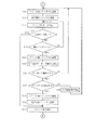
図3は、メイン基板2の制御回路5による起動処理を示している。この図3において、携帯型コードリーダ1の電源をオンすると、メイン基板2、キーボード基板3、表示基板4がそれぞれ起動処理を実行する。
Next, the operation of the above configuration will be described.
FIG. 3 shows a startup process by the
図3は、メイン基板2の起動処理を示すフローチャートである。この図3に示すように、メイン基板2の制御回路5は、無線モジュール7のアンテナをゲインの低いパターンアンテナ10に設定してから(S1)、Bluetooth無線の相手局を表示基板4に設定すると共に(S2)、表示基板4に表示データを送信する(S3)。これにより、表示基板4に対してBluetoothにより表示データが送信されるので、表示基板4の表示装置18には初期画面が表示される。
FIG. 3 is a flowchart showing the startup process of the
次に、Bluetooth無線の相手局をキーボード基板3に設定し(S4)、キーボード操作があるまで待機する(S5)。
ユーザによりキーボード操作が行われると(S5:YES)、その内容を確認し(S6)、バーコード読取以外の処理を指示するものである場合には(S6:NO)、その内容に基づいた処理を実施し(S13)、再びキーボード操作待機状態となる(S5)。ユーザによりバーコード読取処理の指示が行なわれたことを確認した場合には(S6:YES)、商品のバーコード読取を行ってから(S7)、無線の相手局を表示基板4に設定し(S8)、読取データおよび売上データを表示基板4に送信する(S9)。これにより、表示装置18には、読取データおよび売上データが表示される。
Next, the partner station of the Bluetooth radio is set on the keyboard substrate 3 (S4), and the system waits until there is a keyboard operation (S5).
When a keyboard operation is performed by the user (S5: YES), the content is confirmed (S6), and when an instruction other than barcode reading is instructed (S6: NO), processing based on the content is performed. (S13), and again enters the keyboard operation standby state (S5). If it is confirmed that the user has instructed the barcode reading process (S6: YES), after reading the barcode of the product (S7), the wireless counterpart station is set on the display board 4 ( S8), the read data and the sales data are transmitted to the display substrate 4 (S9). As a result, the read data and the sales data are displayed on the
次に、無線の相手局をキーボード基板3に設定し(S10)、キーボード操作を待つ(S11)。ユーザによりキーボード操作が行われたことを確認した場合に(S11:YES)、データプリント以外の操作であったときは(S12:NO)、追加読取としてステップS7に戻る。ユーザによりデータプリントの指示が行なわれたことを確認した場合には(S12:YES)、アンテナをゲインの高いチップアンテナ9に設定し(S14)、相手局をプリンタに設定した上で(S15)、プリンタに売上データを送信する(S16)。この場合、この売上データはブロック単位で送信され、ブロック送信ごとに送信データが終了したかどうかの確認を行うようになっている(S17)。送信データが終了していない場合には(S17:NO)、キーボード確認のための規定のインターバル(たとえば0.1秒)になったかどうかを確認し(S18)、インターバルに達していない場合には(S19:NO)、ステップS16に戻って次のブロックを送信する。
Next, a wireless counterpart station is set on the keyboard board 3 (S10), and a keyboard operation is awaited (S11). When it is confirmed that the keyboard operation has been performed by the user (S11: YES), if the operation is other than data printing (S12: NO), the process returns to step S7 as additional reading. When it is confirmed that the user has instructed data printing (S12: YES), the antenna is set to the
規定のインターバルに達した場合には(S18:YES)、アンテナをゲインの低いパターンアンテナ10に設定すると共に(S19)、無線の相手局をキーボード基板3に設定してから(S20)、キーボード操作があったかどうかの確認を行う(S21)。キーボード操作が確認されなかった場合には(S22:NO)、ステップS14に戻ってプリンタへの売上データの送信を継続する。キーボード操作が行われたことを確認した場合には(S21:YES)、その内容を確認し(S22)、プリンタへの送信を停止するものでない場合には(S22:NO)、その内容に基づいた処理を実施してから(S26)、ステップS14に戻る。プリンタへの送信停止の指示を受けた場合には(S22:YES)、アンテナをゲインの高いチップアンテナ9に設定すると共に(S23)、無線の相手局をプリンタに設定し(S24)、プリンタの紙送りなどのプリンタ終了処理を行い(S25)、ステップS1に戻る。ステップS17にて送信データ終了であった場合にも、「YES」と判断してステップS25の処理に移行する。
以上の動作により、メイン基板2は、キーボード基板3及び表示基板4との間でBluetooth通信により入力データまたは出力データの入出力が行なわれる。
When the specified interval is reached (S18: YES), the antenna is set to the
Through the above operation, the
このような実施例によれば、メイン基板2が有するBluetooth通信機能を利用して他の機能基板であるキーボード基板3及び表示基板4とBluetooth通信によりデータの入出力を行なうようにしたので、複数の基板間を光通信によりデータ通信を実行する構成のものと違って、メイン基板2の構成が複雑化することなく実施することができる。
According to such an embodiment, since the Bluetooth communication function of the
また、メイン基板2が外部装置であるプリンタと通信するときは大出力で行ない、携帯型コードリーダ1内部のキーボード基板3または表示基板4と通信するときは小出力で行なうようにしたので、Bluetoothによる通信が他のBluetooth通信の障害となってしまうことを防止できる。
Further, when the
さらに、このようにBluetooth通信の出力を切替える手段として、チップアンテナ9とパターンアンテナ10とを切替えるようにしたので、ソフトにより一つのアンテナのゲインを切替える構成のものと違って、ソフトが複雑化することなく容易に実施することができる。
In addition, since the
しかも、Bluetooth通信による情報伝達は無線によるものであるので、機能基板を任意の位置へ実装することが可能であり、形状への制約が無く、電源用のピンコネクタ24の接続だけですむ。また、メイン基板2のアンテナのうち外部機器であるプリンタとの通信用として、ゲインの高いチップアンテナ9を使用するが、キーボード基板3及び表示基板4のアンテナはゲインが低くてもよいことから、パターンアンテナ10を使用することによってコストを抑制することができる。
In addition, since the information transmission by Bluetooth communication is wireless, the functional board can be mounted at an arbitrary position, there is no restriction on the shape, and it is only necessary to connect the
本発明は、上記実施例に限定されることなく、次のように変形または拡張できる。
メイン基板に搭載されているパターンアンテナ10を省略し、チップアンテナ9に対する出力を切替えるようにしてもよいし、チップアンテナ9を省略し、パターンアンテナ10に対する出力を切替えるようにしてもよい。
無線通信手段としてBluetooth通信回路に代えて、メイン基板の外部との通信方法がRFIDの場合は、メイン基板をRFID親局に設定し、機能基板にRFID子局に設定し、それらの間でRFIDタグ通信を行なうようにしてもよい。
The present invention is not limited to the above embodiment, but can be modified or expanded as follows.
The
If the communication method with the outside of the main board is RFID instead of the Bluetooth communication circuit as a wireless communication means, the main board is set as the RFID master station, the RFID board is set as the function board, and the RFID is set between them. Tag communication may be performed.
図面中、1は携帯型コードリーダ(携帯型情報読取端末)、2はメイン基板、3はキーボード基板(機能基板)、4は表示基板(機能基板)、8はBluetooth通信回路(第1の無線通信手段)、9はチップアンテナ(出力切替手段)、10はパターンアンテナ(出力切替手段)、13は切替回路(出力切替手段)、16はBluetooth通信回路(第2の無線通信手段)、20はBluetooth通信回路(第2の無線通信手段)である。 In the drawings, 1 is a portable code reader (portable information reading terminal), 2 is a main board, 3 is a keyboard board (functional board), 4 is a display board (functional board), and 8 is a Bluetooth communication circuit (first wireless). Communication means), 9 a chip antenna (output switching means), 10 a pattern antenna (output switching means), 13 a switching circuit (output switching means), 16 a Bluetooth communication circuit (second wireless communication means), 20 Bluetooth communication circuit (second wireless communication means).
Claims (6)
前記第1の無線通信手段を含む端末全体の動作を制御する制御手段を有したメイン基板と、
前記制御手段に対してデータを出力する出力手段または前記制御手段が出力したデータを入力する入力手段などの所定の機能を有すると共に第2の無線通信手段を有した複数の機能基板とを備え、
前記第1の無線通信手段は、ゲインの小さなパターンアンテナ及びゲインの大きなチップアンテナと、通信出力を小出力にする場合には前記パターンアンテナを選択し、大出力にする場合には前記チップアンテナを選択する出力切替手段とを備えて構成され、
前記制御手段は、前記第1の無線手段を通じて前記複数の機能基板の第2の無線通信手段と順に小出力で通信し、前記外部装置と通信する必要が生じた場合は大出力で通信するように前記出力切替手段を制御することを特徴とする携帯型情報読取端末。 A portable information reading terminal comprising a first wireless communication means for performing wireless communication with an external device,
A main board having control means for controlling the operation of the entire terminal including the first wireless communication means;
And a plurality of functional substrate having a second wireless communication unit as well as have a predetermined function such as an input means for inputting data output means or the control means outputs the data to said control means outputs ,
The first wireless communication means selects a pattern antenna with a small gain and a chip antenna with a large gain, selects the pattern antenna when the communication output is small, and selects the chip antenna when the communication output is large. And an output switching means to select,
The control means communicates with the second wireless communication means of the plurality of functional boards sequentially through the first wireless means with a small output, and communicates with a high output when it is necessary to communicate with the external device. A portable information reading terminal characterized by controlling the output switching means .
前記第2の無線通信手段は、Bluetoothのスレーブに設定されていることを特徴とする請求項1ないし4の何れかに記載の携帯型情報読取端末。 The first wireless communication means is set to a Bluetooth (registered trademark) master,
5. The portable information reading terminal according to claim 1, wherein the second wireless communication means is set as a Bluetooth slave .
前記第2の無線通信手段は、RFIDの子局に設定されていることを特徴とする請求項1ないし5の何れかに記載の携帯型情報読取端末。 The first wireless communication means is set as an RFID master station,
The portable information reading terminal according to any one of claims 1 to 5, wherein the second wireless communication means is set to an RFID slave station .
Priority Applications (1)
| Application Number | Priority Date | Filing Date | Title |
|---|---|---|---|
| JP2005304429A JP4475219B2 (en) | 2005-10-19 | 2005-10-19 | Portable information reader |
Applications Claiming Priority (1)
| Application Number | Priority Date | Filing Date | Title |
|---|---|---|---|
| JP2005304429A JP4475219B2 (en) | 2005-10-19 | 2005-10-19 | Portable information reader |
Publications (2)
| Publication Number | Publication Date |
|---|---|
| JP2007114952A JP2007114952A (en) | 2007-05-10 |
| JP4475219B2 true JP4475219B2 (en) | 2010-06-09 |
Family
ID=38097079
Family Applications (1)
| Application Number | Title | Priority Date | Filing Date |
|---|---|---|---|
| JP2005304429A Expired - Fee Related JP4475219B2 (en) | 2005-10-19 | 2005-10-19 | Portable information reader |
Country Status (1)
| Country | Link |
|---|---|
| JP (1) | JP4475219B2 (en) |
-
2005
- 2005-10-19 JP JP2005304429A patent/JP4475219B2/en not_active Expired - Fee Related
Also Published As
| Publication number | Publication date |
|---|---|
| JP2007114952A (en) | 2007-05-10 |
Similar Documents
| Publication | Publication Date | Title |
|---|---|---|
| CN102780516B (en) | Data communications system, information processing terminal, IC card, reader/writer, and operation method | |
| CN101238478B (en) | Data communication system, device for executing ic card function, control method for the device, and information processing terminal | |
| US7543746B2 (en) | Portable terminal system including portable terminal mounting base | |
| US20100259364A1 (en) | Radio frequency identification reader | |
| JP4412409B2 (en) | Information processing apparatus, information processing system, information processing method, and program | |
| JP5143713B2 (en) | Process management method, process management system | |
| JP2006195931A (en) | Rfid reader/writer-incorporating tablet pen | |
| JP4475219B2 (en) | Portable information reader | |
| US20150186686A1 (en) | Reader and information processing system employing same | |
| KR20190033767A (en) | Multi-channel rf system including low power information and communication technology devices | |
| JP5028319B2 (en) | Communication system and communication method | |
| JP2007011838A (en) | Rfid type information management system | |
| EP4020319A1 (en) | Rfid tag | |
| JP2008084196A (en) | Individual management system, electronic circuit board and electronic equipment | |
| JP2005148820A (en) | Rfid device | |
| JP2011150661A (en) | Portable electronic device and portable electronic device control method | |
| CN107358271B (en) | Mobile terminal and reading and writing method of identification code thereof | |
| JP2015128287A (en) | Information transfer processing system | |
| JP2007293572A (en) | Rfid reader/writer | |
| CN110070149B (en) | Operating system and operating method for performing parameter setting on a large number of electronic devices | |
| JP5261149B2 (en) | Reader / writer for information storage media | |
| CN112165544B (en) | Electronic equipment communication control method and device and electronic equipment | |
| KR100779747B1 (en) | Secure Device combo card with RF communication function for a mobile terminal and method for RF communication of Secure Device combo card | |
| JP2013168082A (en) | Electronic bookmark system, electronic bookmark and electronic book terminal | |
| US20060027654A1 (en) | Card reader and data transmission method therefor |
Legal Events
| Date | Code | Title | Description |
|---|---|---|---|
| A621 | Written request for application examination |
Free format text: JAPANESE INTERMEDIATE CODE: A621 Effective date: 20071031 |
|
| A977 | Report on retrieval |
Free format text: JAPANESE INTERMEDIATE CODE: A971007 Effective date: 20090330 |
|
| A131 | Notification of reasons for refusal |
Free format text: JAPANESE INTERMEDIATE CODE: A131 Effective date: 20090630 |
|
| A521 | Written amendment |
Free format text: JAPANESE INTERMEDIATE CODE: A523 Effective date: 20090831 |
|
| TRDD | Decision of grant or rejection written | ||
| A01 | Written decision to grant a patent or to grant a registration (utility model) |
Free format text: JAPANESE INTERMEDIATE CODE: A01 Effective date: 20100216 |
|
| A01 | Written decision to grant a patent or to grant a registration (utility model) |
Free format text: JAPANESE INTERMEDIATE CODE: A01 |
|
| A61 | First payment of annual fees (during grant procedure) |
Free format text: JAPANESE INTERMEDIATE CODE: A61 Effective date: 20100301 |
|
| R150 | Certificate of patent or registration of utility model |
Ref document number: 4475219 Country of ref document: JP Free format text: JAPANESE INTERMEDIATE CODE: R150 Free format text: JAPANESE INTERMEDIATE CODE: R150 |
|
| FPAY | Renewal fee payment (event date is renewal date of database) |
Free format text: PAYMENT UNTIL: 20130319 Year of fee payment: 3 |
|
| S531 | Written request for registration of change of domicile |
Free format text: JAPANESE INTERMEDIATE CODE: R313531 |
|
| FPAY | Renewal fee payment (event date is renewal date of database) |
Free format text: PAYMENT UNTIL: 20130319 Year of fee payment: 3 |
|
| R350 | Written notification of registration of transfer |
Free format text: JAPANESE INTERMEDIATE CODE: R350 |
|
| FPAY | Renewal fee payment (event date is renewal date of database) |
Free format text: PAYMENT UNTIL: 20130319 Year of fee payment: 3 |
|
| FPAY | Renewal fee payment (event date is renewal date of database) |
Free format text: PAYMENT UNTIL: 20130319 Year of fee payment: 3 |
|
| FPAY | Renewal fee payment (event date is renewal date of database) |
Free format text: PAYMENT UNTIL: 20140319 Year of fee payment: 4 |
|
| R250 | Receipt of annual fees |
Free format text: JAPANESE INTERMEDIATE CODE: R250 |
|
| R250 | Receipt of annual fees |
Free format text: JAPANESE INTERMEDIATE CODE: R250 |
|
| R250 | Receipt of annual fees |
Free format text: JAPANESE INTERMEDIATE CODE: R250 |
|
| R250 | Receipt of annual fees |
Free format text: JAPANESE INTERMEDIATE CODE: R250 |
|
| R250 | Receipt of annual fees |
Free format text: JAPANESE INTERMEDIATE CODE: R250 |
|
| R250 | Receipt of annual fees |
Free format text: JAPANESE INTERMEDIATE CODE: R250 |
|
| LAPS | Cancellation because of no payment of annual fees |