JP4473504B2 - Management device for controlling appliances by power line communication and control method thereof - Google Patents
Management device for controlling appliances by power line communication and control method thereof Download PDFInfo
- Publication number
- JP4473504B2 JP4473504B2 JP2002367803A JP2002367803A JP4473504B2 JP 4473504 B2 JP4473504 B2 JP 4473504B2 JP 2002367803 A JP2002367803 A JP 2002367803A JP 2002367803 A JP2002367803 A JP 2002367803A JP 4473504 B2 JP4473504 B2 JP 4473504B2
- Authority
- JP
- Japan
- Prior art keywords
- power line
- modulation
- signal
- modulation method
- unit
- Prior art date
- Legal status (The legal status is an assumption and is not a legal conclusion. Google has not performed a legal analysis and makes no representation as to the accuracy of the status listed.)
- Expired - Fee Related
Links
Images


Classifications
-
- H—ELECTRICITY
- H04—ELECTRIC COMMUNICATION TECHNIQUE
- H04L—TRANSMISSION OF DIGITAL INFORMATION, e.g. TELEGRAPHIC COMMUNICATION
- H04L12/00—Data switching networks
- H04L12/28—Data switching networks characterised by path configuration, e.g. LAN [Local Area Networks] or WAN [Wide Area Networks]
- H04L12/2803—Home automation networks
- H04L12/2816—Controlling appliance services of a home automation network by calling their functionalities
- H04L12/282—Controlling appliance services of a home automation network by calling their functionalities based on user interaction within the home
-
- H—ELECTRICITY
- H02—GENERATION; CONVERSION OR DISTRIBUTION OF ELECTRIC POWER
- H02J—CIRCUIT ARRANGEMENTS OR SYSTEMS FOR SUPPLYING OR DISTRIBUTING ELECTRIC POWER; SYSTEMS FOR STORING ELECTRIC ENERGY
- H02J13/00—Circuit arrangements for providing remote indication of network conditions, e.g. an instantaneous record of the open or closed condition of each circuitbreaker in the network; Circuit arrangements for providing remote control of switching means in a power distribution network, e.g. switching in and out of current consumers by using a pulse code signal carried by the network
- H02J13/00006—Circuit arrangements for providing remote indication of network conditions, e.g. an instantaneous record of the open or closed condition of each circuitbreaker in the network; Circuit arrangements for providing remote control of switching means in a power distribution network, e.g. switching in and out of current consumers by using a pulse code signal carried by the network characterised by information or instructions transport means between the monitoring, controlling or managing units and monitored, controlled or operated power network element or electrical equipment
- H02J13/00007—Circuit arrangements for providing remote indication of network conditions, e.g. an instantaneous record of the open or closed condition of each circuitbreaker in the network; Circuit arrangements for providing remote control of switching means in a power distribution network, e.g. switching in and out of current consumers by using a pulse code signal carried by the network characterised by information or instructions transport means between the monitoring, controlling or managing units and monitored, controlled or operated power network element or electrical equipment using the power network as support for the transmission
- H02J13/00009—Circuit arrangements for providing remote indication of network conditions, e.g. an instantaneous record of the open or closed condition of each circuitbreaker in the network; Circuit arrangements for providing remote control of switching means in a power distribution network, e.g. switching in and out of current consumers by using a pulse code signal carried by the network characterised by information or instructions transport means between the monitoring, controlling or managing units and monitored, controlled or operated power network element or electrical equipment using the power network as support for the transmission using pulsed signals
-
- H—ELECTRICITY
- H04—ELECTRIC COMMUNICATION TECHNIQUE
- H04B—TRANSMISSION
- H04B3/00—Line transmission systems
- H04B3/54—Systems for transmission via power distribution lines
-
- H—ELECTRICITY
- H04—ELECTRIC COMMUNICATION TECHNIQUE
- H04L—TRANSMISSION OF DIGITAL INFORMATION, e.g. TELEGRAPHIC COMMUNICATION
- H04L12/00—Data switching networks
- H04L12/28—Data switching networks characterised by path configuration, e.g. LAN [Local Area Networks] or WAN [Wide Area Networks]
- H04L12/2803—Home automation networks
-
- H—ELECTRICITY
- H04—ELECTRIC COMMUNICATION TECHNIQUE
- H04L—TRANSMISSION OF DIGITAL INFORMATION, e.g. TELEGRAPHIC COMMUNICATION
- H04L43/00—Arrangements for monitoring or testing data switching networks
- H04L43/08—Monitoring or testing based on specific metrics, e.g. QoS, energy consumption or environmental parameters
- H04L43/0805—Monitoring or testing based on specific metrics, e.g. QoS, energy consumption or environmental parameters by checking availability
- H04L43/0811—Monitoring or testing based on specific metrics, e.g. QoS, energy consumption or environmental parameters by checking availability by checking connectivity
-
- H—ELECTRICITY
- H04—ELECTRIC COMMUNICATION TECHNIQUE
- H04L—TRANSMISSION OF DIGITAL INFORMATION, e.g. TELEGRAPHIC COMMUNICATION
- H04L43/00—Arrangements for monitoring or testing data switching networks
- H04L43/50—Testing arrangements
-
- H—ELECTRICITY
- H04—ELECTRIC COMMUNICATION TECHNIQUE
- H04B—TRANSMISSION
- H04B2203/00—Indexing scheme relating to line transmission systems
- H04B2203/54—Aspects of powerline communications not already covered by H04B3/54 and its subgroups
- H04B2203/5404—Methods of transmitting or receiving signals via power distribution lines
- H04B2203/5416—Methods of transmitting or receiving signals via power distribution lines by adding signals to the wave form of the power source
-
- H—ELECTRICITY
- H04—ELECTRIC COMMUNICATION TECHNIQUE
- H04B—TRANSMISSION
- H04B2203/00—Indexing scheme relating to line transmission systems
- H04B2203/54—Aspects of powerline communications not already covered by H04B3/54 and its subgroups
- H04B2203/5429—Applications for powerline communications
- H04B2203/5445—Local network
-
- H—ELECTRICITY
- H04—ELECTRIC COMMUNICATION TECHNIQUE
- H04B—TRANSMISSION
- H04B2203/00—Indexing scheme relating to line transmission systems
- H04B2203/54—Aspects of powerline communications not already covered by H04B3/54 and its subgroups
- H04B2203/5429—Applications for powerline communications
- H04B2203/545—Audio/video application, e.g. interphone
-
- H—ELECTRICITY
- H04—ELECTRIC COMMUNICATION TECHNIQUE
- H04B—TRANSMISSION
- H04B2203/00—Indexing scheme relating to line transmission systems
- H04B2203/54—Aspects of powerline communications not already covered by H04B3/54 and its subgroups
- H04B2203/5462—Systems for power line communications
- H04B2203/5483—Systems for power line communications using coupling circuits
-
- H—ELECTRICITY
- H04—ELECTRIC COMMUNICATION TECHNIQUE
- H04B—TRANSMISSION
- H04B2203/00—Indexing scheme relating to line transmission systems
- H04B2203/54—Aspects of powerline communications not already covered by H04B3/54 and its subgroups
- H04B2203/5462—Systems for power line communications
- H04B2203/5491—Systems for power line communications using filtering and bypassing
-
- H—ELECTRICITY
- H04—ELECTRIC COMMUNICATION TECHNIQUE
- H04L—TRANSMISSION OF DIGITAL INFORMATION, e.g. TELEGRAPHIC COMMUNICATION
- H04L12/00—Data switching networks
- H04L12/28—Data switching networks characterised by path configuration, e.g. LAN [Local Area Networks] or WAN [Wide Area Networks]
- H04L12/2803—Home automation networks
- H04L12/283—Processing of data at an internetworking point of a home automation network
- H04L12/2836—Protocol conversion between an external network and a home network
-
- H—ELECTRICITY
- H04—ELECTRIC COMMUNICATION TECHNIQUE
- H04L—TRANSMISSION OF DIGITAL INFORMATION, e.g. TELEGRAPHIC COMMUNICATION
- H04L12/00—Data switching networks
- H04L12/28—Data switching networks characterised by path configuration, e.g. LAN [Local Area Networks] or WAN [Wide Area Networks]
- H04L12/2803—Home automation networks
- H04L2012/284—Home automation networks characterised by the type of medium used
- H04L2012/2843—Mains power line
-
- H—ELECTRICITY
- H04—ELECTRIC COMMUNICATION TECHNIQUE
- H04L—TRANSMISSION OF DIGITAL INFORMATION, e.g. TELEGRAPHIC COMMUNICATION
- H04L41/00—Arrangements for maintenance, administration or management of data switching networks, e.g. of packet switching networks
- H04L41/06—Management of faults, events, alarms or notifications
-
- Y—GENERAL TAGGING OF NEW TECHNOLOGICAL DEVELOPMENTS; GENERAL TAGGING OF CROSS-SECTIONAL TECHNOLOGIES SPANNING OVER SEVERAL SECTIONS OF THE IPC; TECHNICAL SUBJECTS COVERED BY FORMER USPC CROSS-REFERENCE ART COLLECTIONS [XRACs] AND DIGESTS
- Y02—TECHNOLOGIES OR APPLICATIONS FOR MITIGATION OR ADAPTATION AGAINST CLIMATE CHANGE
- Y02B—CLIMATE CHANGE MITIGATION TECHNOLOGIES RELATED TO BUILDINGS, e.g. HOUSING, HOUSE APPLIANCES OR RELATED END-USER APPLICATIONS
- Y02B70/00—Technologies for an efficient end-user side electric power management and consumption
- Y02B70/30—Systems integrating technologies related to power network operation and communication or information technologies for improving the carbon footprint of the management of residential or tertiary loads, i.e. smart grids as climate change mitigation technology in the buildings sector, including also the last stages of power distribution and the control, monitoring or operating management systems at local level
-
- Y—GENERAL TAGGING OF NEW TECHNOLOGICAL DEVELOPMENTS; GENERAL TAGGING OF CROSS-SECTIONAL TECHNOLOGIES SPANNING OVER SEVERAL SECTIONS OF THE IPC; TECHNICAL SUBJECTS COVERED BY FORMER USPC CROSS-REFERENCE ART COLLECTIONS [XRACs] AND DIGESTS
- Y02—TECHNOLOGIES OR APPLICATIONS FOR MITIGATION OR ADAPTATION AGAINST CLIMATE CHANGE
- Y02B—CLIMATE CHANGE MITIGATION TECHNOLOGIES RELATED TO BUILDINGS, e.g. HOUSING, HOUSE APPLIANCES OR RELATED END-USER APPLICATIONS
- Y02B90/00—Enabling technologies or technologies with a potential or indirect contribution to GHG emissions mitigation
- Y02B90/20—Smart grids as enabling technology in buildings sector
-
- Y—GENERAL TAGGING OF NEW TECHNOLOGICAL DEVELOPMENTS; GENERAL TAGGING OF CROSS-SECTIONAL TECHNOLOGIES SPANNING OVER SEVERAL SECTIONS OF THE IPC; TECHNICAL SUBJECTS COVERED BY FORMER USPC CROSS-REFERENCE ART COLLECTIONS [XRACs] AND DIGESTS
- Y04—INFORMATION OR COMMUNICATION TECHNOLOGIES HAVING AN IMPACT ON OTHER TECHNOLOGY AREAS
- Y04S—SYSTEMS INTEGRATING TECHNOLOGIES RELATED TO POWER NETWORK OPERATION, COMMUNICATION OR INFORMATION TECHNOLOGIES FOR IMPROVING THE ELECTRICAL POWER GENERATION, TRANSMISSION, DISTRIBUTION, MANAGEMENT OR USAGE, i.e. SMART GRIDS
- Y04S20/00—Management or operation of end-user stationary applications or the last stages of power distribution; Controlling, monitoring or operating thereof
- Y04S20/20—End-user application control systems
-
- Y—GENERAL TAGGING OF NEW TECHNOLOGICAL DEVELOPMENTS; GENERAL TAGGING OF CROSS-SECTIONAL TECHNOLOGIES SPANNING OVER SEVERAL SECTIONS OF THE IPC; TECHNICAL SUBJECTS COVERED BY FORMER USPC CROSS-REFERENCE ART COLLECTIONS [XRACs] AND DIGESTS
- Y04—INFORMATION OR COMMUNICATION TECHNOLOGIES HAVING AN IMPACT ON OTHER TECHNOLOGY AREAS
- Y04S—SYSTEMS INTEGRATING TECHNOLOGIES RELATED TO POWER NETWORK OPERATION, COMMUNICATION OR INFORMATION TECHNOLOGIES FOR IMPROVING THE ELECTRICAL POWER GENERATION, TRANSMISSION, DISTRIBUTION, MANAGEMENT OR USAGE, i.e. SMART GRIDS
- Y04S40/00—Systems for electrical power generation, transmission, distribution or end-user application management characterised by the use of communication or information technologies, or communication or information technology specific aspects supporting them
- Y04S40/12—Systems for electrical power generation, transmission, distribution or end-user application management characterised by the use of communication or information technologies, or communication or information technology specific aspects supporting them characterised by data transport means between the monitoring, controlling or managing units and monitored, controlled or operated electrical equipment
- Y04S40/121—Systems for electrical power generation, transmission, distribution or end-user application management characterised by the use of communication or information technologies, or communication or information technology specific aspects supporting them characterised by data transport means between the monitoring, controlling or managing units and monitored, controlled or operated electrical equipment using the power network as support for the transmission
Description
【0001】
【発明の属する技術分野】
本発明は、電化製品を電灯線通信により制御する管理装置及びその制御方法に関する。
【0002】
【従来の技術】
従来、電灯線通信により家庭内の各電化製品を制御するシステムが存在する。電灯線通信は、各電化製品に電力を供給する電灯線を通信媒体として利用する通信形態である。家庭内に設置された各電化製品に電灯線通信用のモデムを搭載し、また、各電化製品を集中管理する管理装置を設け、この管理装置から各電化製品に対する種々の制御を行う。例えば、管理装置は、冷蔵庫のドアが所定時間以上開いていることを検知し、その旨の情報をテレビ画面上に表示して注意を促したりできる。また、各電化製品の消費電力量の総和が契約電力量を超えないよう制御したりできる(例えば、特許文献1参照)。
【0003】
【特許文献】
特開2002−84658号公報
【0004】
【発明が解決しようとする課題】
しかし、かかる従来の技術では、以下のような問題が生じていた。
【0005】
即ち、電灯線通信に関しては、共通の国際規格が存在せず、各国または地域毎に対応が異なっている。特に、各国または地域毎に、電灯線通信が可能な割当て周波数帯域、電化製品に使用する電圧及び既に使用されている周波数帯域(例えば、ラジオ放送)への漏洩電波の影響などに起因して、国際的調整は困難となっている。
【0006】
日本では、業界団体であるECHONETコンソーシアムを中心に電灯線通信の国内規格が統一されているが、一方、欧州では、電灯線通信に用いる周波数帯域の規定はあるが、モデムの変調方式は定められていない。更に、European Norm 50065-1においてC帯域(125−140kHz)と呼ばれる周波数帯域は、異なる変調方式の衝突回避のためのアクセスプロトコル(Carrier Sense Multiple-Access(CSMA))が規定されている。そのため、CSMAプロトコルさえ守れば種々の変調方式によるシステム構築が可能である。
【0007】
具体的な変調方式としては、ASK(Amplitude-Shift Keying)変調方式、FSK(Frequency-Shift Keying)変調方式、PSK(Phase-Shift Keying)変調方式などがある。各変調方式には一長一短がある。
【0008】
それぞれの変調方式には、一般的に以下の特徴がある。ASK変調方式は、回路を簡単に構成できるという利点がある一方で雑音に弱いという欠点がある。また、PSK変調方式は、雑音に強いという利点である一方で回路構成が複雑となるという欠点がある。FSK方式は、前記ASK変調方式と前記PSK変調方式との中間的特長を持つ。
【0009】
そのため、欧州の電化製品に搭載されるモデムの変調方式は統一化されておらず、電灯線通信機能を持つ電化製品を購入しても、異なる変調方式の電化製品間では電灯線通信ができないという問題があった。
【0010】
本発明は、かかる問題点に鑑みて為されたものであり、電灯線通信に用いるモデムの変調方式が統一されていない欧州においても、同一の変調方式のモデムを搭載した電化製品を買い揃えることなく、家庭内の全電化製品の制御を電灯線通信により行うことができる管理装置及びその制御方法を提供することを目的とする。
【0011】
【課題を解決するための手段】
本発明は、電灯線ネットワークに接続された電灯線モデムを有する機器を管理する管理装置であって、当該機器の電灯線モデムで用いている変調方式を確認するための確認信号を、第1の変調方式を用いて変調する第1の変調部と、当該機器の電灯線モデムで用いている変調方式を確認するための確認信号を、第2の変調方式を用いて変調する第2の変調部と、前記第1の変調部および前記第2の変調部によって変調されたそれぞれの確認信号を、当該電灯線ネットワークに送信する送信部と、当該機器からの信号を受信する受信部と、前記受信部における、それぞれの確認信号に対する応答の有無に基づいて、当該機器の電灯線モデムで用いている変調方式を判定する変調方式判定部と、前記判定部が判定した結果に基づいて、当該機器の電灯線モデムが用いている変調方式を登録する登録部と、を備えた管理装置である。
【0012】
本発明によれば、機器の電灯線モデムで用いている変調方式を確認するための確認信号を複数の変調方式を用いて電灯線ネットワークにそれぞれ送信するので、電灯線ネットワークに変調方式の異なる複数の電灯線モデムが接続している場合でも、それぞれの機器の電灯線モデムで用いている変調方式を登録することができる。ゆえに、同一の変調方式のモデムを搭載した電化製品を買い揃えることなく、電灯線通信による家庭内の電化製品の制御を実現できる。
【0013】
【発明の実施の形態】
第1の発明は、電灯線ネットワークに接続された電灯線モデムを有する機器を管理する管理装置であって、当該機器の電灯線モデムで用いている変調方式を確認するための確認信号を、第1の変調方式を用いて変調する第1の変調部と、当該機器の電灯線モデムで用いている変調方式を確認するための確認信号を、第2の変調方式を用いて変調する第2の変調部と、前記第1の変調部および前記第2の変調部によって変調されたそれぞれの確認信号を、当該電灯線ネットワークに送信する送信部と、当該機器からの信号を受信する受信部と、前記受信部における、それぞれの確認信号に対する応答の有無に基づいて、当該機器の電灯線モデムで用いている変調方式を判定する変調方式判定部と、前記判定部が判定した結果に基づいて、当該機器の電灯線モデムが用いている変調方式を登録する登録部と、を備えた管理装置である。
【0014】
この構成によれば、機器の電灯線モデムで用いている変調方式を確認するための確認信号を複数の変調方式を用いて電灯線ネットワークにそれぞれ送信するので、電灯線ネットワークに変調方式の異なる複数の電灯線モデムが接続している場合でも、それぞれの機器の電灯線モデムで用いている変調方式を登録することができる。ゆえに、同一の変調方式のモデムを搭載した電化製品を買い揃えることなく、電灯線通信による家庭内の電化製品の制御を実現できる。
【0015】
第2の発明は、前記送信部が、当該確認信号を定期的または任意の操作によって送信する管理装置である。
【0016】
この構成によれば、各電化製品が搭載するモデムの変調方式の確認は、定期的に行われるので、新規に購入した電化製品についても、その変調方式を自動的に登録して漏れることなく対応することができる。
【0017】
また、各電化製品が搭載するモデムの変調方式の確認を、定期的にではなく任意の操作により行なうと、新規に電化製品を購入した場合その時点で手動によりその電化製品が搭載したモデムの変調方式を登録できるので、定期的に確認を行う場合のように、新規の電化製品を設置してから自動的に確認動作が行われるまでの間に、その電化製品に対応できないという不都合を解消できる。
【0018】
第3の発明は、電灯線ネットワークに接続された電灯線モデムを有する機器を管理する管理装置であって、当該機器の電灯線モデムから送信された信号を受信する受信部と、当該信号の搬送波の特性が変化する変化点に基づいて、当該機器の電灯線モデムが用いている変調方式を判定する変調方式判定部と、前記判定部が判定した結果に基づいて、当該機器の電灯線モデムが用いている変調方式を登録する登録部と、を備えた管理装置である。
【0019】
この構成によれば、管理装置が認識していない機器が電灯線ネットワークにつながった場合に、機器の電灯線モデムから送信された信号の搬送波の特性が変化する変化点に基づいて、当該機器の電灯線モデムで用いている変調方式を判定することができる。
【0020】
第4の発明は、第3の発明の管理装置であって、当該搬送波の特性は、搬送波の位相、振幅、および周波数のいずれか一つである管理装置である。
【0021】
この構成によれば、管理装置が認識していない機器が電灯線ネットワークにつながった場合に、機器の電灯線モデムから送信された信号の搬送波の位相、振幅、または周波数が変化する変化点に基づいて、当該機器の電灯線モデムで用いている変調方式を判定することができる。
【0022】
第5の発明は、第1または第2の発明の管理装置であって、前記第1の変調部および前記第2の変調部は、当該第1の変調方式および当該第2の変調方式として、ASK変調方式、FSK変調方式、PSK変調方式のいずれか二つを用いる管理装置である。
【0023】
この構成によれば、ASK変調方式、FSK変調方式及びPSK変調方式のモデムを搭載された電化製品間において、これらのモデムの変調方式が異なっていても、管理装置が各電化製品に搭載されたモデムの変調方式に適合した制御を行うことが可能となるので、同一の変調方式のモデムを搭載した電化製品を買い揃えることなく、電灯線通信による電化製品の制御を実現できる。
【0024】
第6の発明は、第1、2、および5のいずれかの発明の管理装置であって、更に、当該第1の変調方式を用いた第1の信号を当該第2の変調方式を用いた第2の信号に変換する変換部を備えた管理装置である。
【0025】
この構成によれば、通信方式の異なる電灯線モデム間で通信を行うことが可能になる。
【0026】
第7の発明は、第6の発明の管理装置であって、当該電力線ネットワークは、当該第1の変調方式を用いて通信を行う第1の電灯線モデムを有する第1の機器と当該第2の変調方式を用いて通信を行う第2の電灯線モデムを有する機器を含み、前記受信部は、当該第1の電灯線モデムから送信され、当該第1の変調方式を用いた第1の信号を受信し、前記変換部は、該第1の変調方式を用いた第1の信号を当該第2の変調方式を用いた第2の信号に変換し、前記送信部は、当該第2の信号を当該第2の電灯線モデムに送信する管理装置である。
この構成によれば、通信方式の異なる電灯線モデム間で通信を行うことが可能になる。
【0027】
第8の発明は、第7の発明の管理装置と、前記第1の電灯線モデムを搭載した冷蔵庫と、前記第2の電灯線モデムを搭載したテレビと、を備え、前記冷蔵庫は、前記冷蔵庫のドアが所定時間以上開いている場合、当該ドアが開いている状態を示す信号を前記第1の電灯線モデム介して送信し、前記管理装置は、当該信号に用いられている変調方式を当該第1の変調方式から当該第2の変調方式に変換し、当該信号を前記テレビへ送信し、前記テレビは、当該信号に基づいて、前記テレビの表示部にアラームメッセージを表示する電灯線通信システムである。
この構成によれば、変調方式が互いに異なる冷蔵庫とテレビ間の通信を行うことが可能になる。
【0028】
第9の発明は、電灯線ネットワークに接続された電灯線モデムを有する機器を管理する管理方法であって、当該機器の電灯線モデムで用いている変調方式を確認するための確認信号を、第1の変調方式を用いて変調し、当該機器の電灯線モデムで用いている変調方式を確認するための確認信号を、第2の変調方式を用いて変調し、前記第1の変調部および前記第2の変調部によって変調されたそれぞれの確認信号を、当該電灯線ネットワークに送信し、当該機器からの信号を受信し、それぞれの確認信号に対する応答の有無に基づいて、当該機器の電灯線モデムで用いている変調方式を判定し、判定した結果に基づいて、当該機器の電灯線モデムが用いている変調方式を登録する管理方法である。
この構成によれば、機器の電灯線モデムで用いている変調方式を確認するための確認信号を複数の変調方式を用いて電灯線ネットワークにそれぞれ送信するので、電灯線ネットワークに変調方式の異なる複数の電灯線モデムが接続している場合でも、それぞれの機器の電灯線モデムで用いている変調方式を登録することができる。ゆえに、同一の変調方式のモデムを搭載した電化製品を買い揃えることなく、電灯線通信による家庭内の電化製品の制御を実現できる。
【0032】
以下、本発明の実施の形態について図面を参照して詳細に説明する。
【0033】
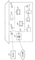
図1は、本発明の一実施の形態に係る管理装置が適用される家庭内ネットワークの構成を示すブロック図である。
【0034】
図1に示すように、家庭内ネットワークには、管理装置100が設けられている。この管理装置100には、家庭内に配置された電化製品が接続されている。また、管理装置100は、通信回線を介して公衆回線網(PSTN, xDSL, WLL, Cable等)102との間で各種データ通信を行う。
【0035】
管理装置100と各電化製品との間は、電灯線103により接続されている。電灯線103は、電力会社101からブレーカ(B)などを経由して電力供給を受け、各電化製品に電力を供給する共に、管理装置100と、室内照明104、エアコン105、室内照明106、テレビ107、テレビ108、洗濯機109、電子レンジ110、冷蔵庫111及び室内照明112等の電化製品との間の各種信号の送受信を行う通信路の媒体として使用される。すなわち、電灯線103は、管理装置100が各電化製品の集中管理を行うための家庭内ネットワークシステムの通信路を形成している。
【0036】
上記管理装置100や各電化製品は、電灯線103の電圧へ信号を乗せて、すなわち、電力供給中の電灯線103に搬送波を重ねて送信する一方、電灯線103の電圧から信号を抽出して受信するPLC(Power Line Communication)ユニットを備えている。このPLCユニットを用いることにより、管理装置100及び各電化製品は、通信路として電灯線103を用いて情報の授受を行うことができる。
【0037】
各電化製品に設けられたPLCユニットは、電灯線103を用いて通信を行う場合に各電化製品に予め設定された変調方式で変復調処理を実行して通信を実現するモデムとして機能する。一方、管理装置100に設けられたPLCユニットは、各電化製品の変調方式に対応できるように複数の変調方式で変復調処理を実行して通信を実現するモデムとして機能する。単一の変調方式を有する電化製品に設けられたPLCユニットに対して、管理装置100に設けられたPLCユニットを、マルチPLCユニットと呼ぶものとする。
【0038】
図2は、本実施の形態に係る管理装置100の概略構成を示すブロック図である。
【0039】
同図に示すように、管理装置100は、装置全体の制御を行うCPU201と、このCPU201が装置全体の制御を行う際に実行するプログラムが格納されたメモリ202と、公衆回線網102と接続された通信回線とのインターフェイスを取る外部インターフェイス203と、上述のマルチPLCユニット204と、を備えている。
【0040】
また、メモリ202には、マルチPLCユニット204が各電化製品と通信を行う場合に参照されるテーブル(以下、「電化製品情報テーブル」という)が格納されている。
【0041】
図3は、本実施の形態に係る管理装置100のメモリ202に格納される電化製品情報テーブルの一例を示す図である。ここでは、既に電化製品の情報が登録されている場合について示している。
【0042】
電化製品テーブル300には、電灯線103に接続された電化製品301に対応して、各電化製品が搭載するPLCユニットが保有する変調方式302、データ伝送速度303、アドレス304及びプロトコル種別等その他の情報305が登録される。図3の例を用いれば、エアコン105が搭載するPLCユニットは、変調方式としてPSKによる変調方式を保有し、そのデータ伝送速度が5400bpsである。また、エアコン105のアドレスは0X0105であり、その他の情報としてECHONETに対応可能であることが登録されている。
【0043】
図4は、本実施の形態に係る管理装置100のマルチPLCユニット204の構成を示すブロック図である。
【0044】
図4に示すマルチPLCユニット204において、カプラ401は、電灯線通信に用いられる帯域の信号だけを抽出する。BPF(Band Pass Filter)402は、モータ等が発生させるノイズを除去し、電灯線通信に必要な信号だけを取得する。AFE(Analog Front End)403は、BPFが抽出した信号にアナログ/デジタル変換処理を施す。
【0045】
変調部404は、CPU201から指示された変調方式を選択し、各電化製品への送信信号に変調処理を施す。復調部405は、各電化製品からの受信信号の変調方式を判断し、その変調方式に応じて復調処理を施す。
【0046】
変調部404は、ASK変調部406、FSK変調部407、PSK変調部408及び変調部切替部409を備えている。ASK変調部406、FSK変調部407及びPSK変調部408は、それぞれ送信信号にASK方式による変調処理、FSK方式による変調処理及びPSK方式による変調処理を施す。なお、各変調部406〜408は、複数の変調速度(データ伝送速度)に対応可能な構成となっている。変調部切替部409は、CPU201からの指示に応じて送信信号の送出先を、ASK変調部406、FSK変調部407及びPSK変調部408の間で切り替える。
【0047】
復調部405は、ASK復調部410、FSK復調部411、PSK復調部412、受信変調信号判定部413及びエネルギー検出部414を備えている。ASK復調部410、FSK復調部411及びPSK復調部412は、それぞれ受信信号にASK方式による復調処理、FSK方式による復調処理及びPSK方式による復調処理を施す。なお、各復調部410〜412は、複数の復調速度(データ伝送速度)に対応可能な構成となっている。
【0048】
受信変調信号判定部413は、受信信号の変調方式を判定し、受信信号の復調を行う復調部を、ASK復調部410、FSK復調部411及びPSK復調部412の間で切り替える。エネルギー検出部414は、予め定められた周波数帯域において一定値以上のエネルギーを有する受信信号を検出し、その旨を受信変調信号判定部413及びCPU201に通知する。この通知を受けると、受信変調信号判定部413は、受信信号の変調方式の判定処理を開始する。一方、CPU201は、受信信号の存在を認識し、電化製品への送信信号の出力を停止する。なお、受信変調信号判定部413における受信信号の変調方式の判定処理については後述する。
【0049】
図5は、本実施の形態に係る管理装置100と電灯線103を介して接続された電化製品の概略構成を示すブロック図である。図5においては、電化製品の一例として、テレビ107の構成について説明する。
【0050】
同図に示すように、テレビ107は、テレビ全体の制御を行うCPU501と、このCPU501がテレビ全体の制御を行う際に実行するプログラムや電灯線通信を行う場合に必要となる管理装置100のアドレスが格納されたメモリ502と、電灯線103を介して入力された電源を内蔵するマイコン等の構成要素のために調節する電源調節部503と、画像を表示する表示部504と、電灯線通信を実現するためのモデムとして機能するPLCユニット505と、を備えている。
【0051】
なお、本実施の形態では、メモリ502には管理装置100のアドレスのみが登録された場合について説明するが、これに限定されず、電灯線103に接続された電化製品のうち、自機(テレビ107)が有する変調方式と同一の変調方式を有する電化製品のアドレスを格納するようにしてもよい。この場合には、CPU501の制御により、同一の変調方式を有する電化製品と、管理装置100を介さずに電灯線通信を行うことも可能となる。
【0052】
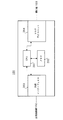
図6は、本実施の形態に係る管理装置100と電灯線103を介して接続された電化製品(テレビ107)のPLCユニット505の構成を示すブロック図である。なお、図6に示すように、テレビ107は、電灯線通信を行う場合の変調方式としてFSK方式による変調処理(以下、「FSK変調」といい、その他の変調方式についても同様とする)を実行するものとする。
【0053】
図6に示すPLCユニット505において、カプラ601は、電灯線通信に用いられる帯域の信号だけを抽出する。BPF(Band Pass Filter)602は、モータ等が発生させるノイズを除去し、電灯線通信に必要な信号だけを取得する。AFE(Analog Front End)603は、BPFが抽出した信号にアナログ/デジタル変換処理を施す。
【0054】
また、FSK変調部604は、管理装置100への送信信号に対してFSK変調処理を施す。FSK復調部605は、管理装置100からの受信信号に対してFSK方式による復調処理を施す。エネルギー検出部606は、予め定められた周波数帯域において一定値以上のエネルギーを有する受信信号を検出し、その旨をFSK復調部605及びCPU501に通知する。この通知を受けると、FSK復調部605は、復調処理を開始する。一方、CPU501は、受信信号の存在を認識し、管理装置100への送信信号の出力を停止する。
【0055】
上記構成を有し、管理装置100は、電灯線103を介して接続された電化製品と電灯線通信を行うが、この電灯線通信を行う際、メモリ202に格納された電化製品情報テーブル300上の情報を参照する。したがって、管理装置100においては、予め電化製品情報テーブル300に情報を登録しておく必要がある。このため、管理装置100は、電灯線103に接続された各電化製品が有する変調方式を確認するための制御信号を定期的にまたは任意の操作により、送信し、その応答信号により各電化製品が有する変調方式等の情報を登録する。また、上記制御信号が送信される前にいずれかの電化製品から何らかの信号を受信した場合にも、その信号を解析することで当該電化製品が有する変調方式等の情報を登録する。
【0056】
まず、各電化製品が有する変調方式を確認するための制御信号を定期的にまたは任意の操作により送信し、その応答信号により各電化製品が有する変調方式等の情報を登録する場合について説明する。
【0057】
図7は、本実施の形態に係る管理装置100から各電化製品に対して変調方式を確認するための制御信号を送信し、応答信号を受信する場合のシーケンス図である。なお、図7においては、電灯線103に接続された電化製品の一つに対するシーケンスを示し、この電化製品は、図5で説明したテレビ107であるものとする。
【0058】
この場合、管理装置100は、電灯線103に接続された各電化製品に対して定期的にまたは任意の操作により、複数の変調方式で順次、各電化製品が有する変調方式を確認する旨の制御信号を送信する。この制御信号は、各電化製品からの応答信号を招待するため、以下、招待信号と呼ぶものとする。
【0059】
ここで、管理装置100と電化製品との間で交換されるデータのフレーム構造について説明する。図8は、本実施の形態に係る管理装置100と電化製品との間で交換されるデータのフレーム構造の模式図の一例である。
【0060】
図8に示すように、管理装置100と電化製品との間で交換されるデータのフレームは、データの開始を示すプリアンブル801、データの発信元を示す発信元アドレス802、データの送信先を示す相手先アドレス803、データの種類を示すデータタイプ804、データの実体データを示すユーザデータ805、データ伝送途中で発生するビット誤りを検出するためのCRC(Cyclic Redundancy Check)806及びデータの終了を示す終結データ807から構成される。
【0061】
上記招待信号が管理装置100から送信される場合には、発信元アドレス802に管理装置100のアドレスが記述され、相手先アドレス803には電灯線103を介して接続された全ての電化製品のアドレス、すなわち、ブロードキャストアドレスが記述される。また、データタイプ804に招待信号である旨が記述され、ユーザデータ805に当該招待信号が示す変調方式等の情報が記述される。
【0062】
図7に示すように、管理装置100は、まず、ASK変調がされた招待信号をテレビ107に送出する(ST701)。管理装置100は、誤動作を回避するため、ASK変調がされた後、一定時間応答を受信しない場合には、このASK変調された招待信号の送出を3回繰り返す。なお、図6で説明したように、テレビ107は、電灯線通信を行う場合の変調方式としてFSK変調を実行するものである。このため、テレビ107は、この招待信号に応答することができない(ST702)。
【0063】
一定時間が経過しても3回目に送出したASK変調された招待信号に応答がない場合、管理装置100は、PSK変調がされた招待信号をテレビ107に送出する(ST703)。PSK変調がされた招待信号についても、ASK変調された招待信号と同様に3回送出される。これに対してもテレビ107は、応答することができない(ST704)。
【0064】
一定時間が経過してもPSK変調された招待信号に応答がない場合、管理装置100は、FSK変調がされた招待信号をテレビ107に送出する(ST705)。上述のように、テレビ107は、FSK変調を実行可能であるため、このFSK変調された招待信号に応答する(ST706)。
【0065】
この応答信号を受信すると、管理装置100は、この電化製品(テレビ107)が有する変調方式がFSK変調であると判断し、メモリ202の電化製品情報テーブル300に変調方式等の情報を登録する。
【0066】
管理装置100は、このような変調方式等の情報の登録処理を、電灯線103に接続された電化製品の全てに対して行う。これにより、メモリ202の電化製品テーブル300には、現時点において電灯線103に接続された電化製品が有する変調方式等の情報が全て登録される。
【0067】
図7に示したシーケンスにおける管理装置100及び電化製品の動作について説明する。図9は図7に示したシーケンスにおける管理装置100の動作を説明するためのフロー図である。図10及び図11は、図7に示したシーケンスにおける電化製品の動作を説明するためのフロー図である。なお、図10は、テレビ107のPLCユニット505の動作を示し、図11は、テレビ107のCPU501の動作を示している。
【0068】
管理装置100は、図9に示すように、まず、ASK変調した招待信号を電化製品に送信する(ST901)。そして、一定時間が経過する前に電化製品から応答信号を受信するかを判断する(ST902)。応答信号を受信した場合には、管理装置100は、電化製品がASK変調した招待信号に応答可能であるとして、電化製品が有する変調方式がASK変調であることをメモリ202内の電化製品情報テーブル300に登録し(ST903)、処理を終了する。このとき、管理装置100は、応答信号の搬送波の変化点に基づいて電化製品のデータ伝送速度も登録する。なお、図7に示すシーケンスでは、テレビ107が有する変調方式がFSK変調であるため、ここでは応答信号は受信されない。
【0069】
一方、ST902で応答信号を受信しない場合には、このASK変調した招待信号を3回電化製品に送信したか判断する(ST904)。このように招待信号を3回送信したかを判断することで、応答信号を受信できなかったような事態に誤動作するのを回避することができる。ASK変調した招待信号を3回送信していない場合には、処理をST901に戻し、ここまでの処理を繰り返す。
【0070】
ASK変調した招待信号を3回送信しているならば、今度はPSK変調した招待信号についてST901〜ST904と同様の処理を行う。すなわち、まず、PSK変調した招待信号を電化製品に送信し(ST905)、一定時間内に応答信号を受信するかを判断する(ST906)。応答信号を受信した場合には、テレがPSK変調した招待信号に応答可能であるとして、電化製品が有する変調方式がPSK変調であることをメモリ202内の電化製品情報テーブル300に登録し(ST907)、処理を終了する。一方、応答信号を受信しない場合には、このPSK変調した招待信号を3回電化製品に送信したか判断する(ST908)。なお、図7に示すシーケンスでは、テレビ107が有する変調方式がFSK変調であるため、ここでは応答信号は受信されない。
【0071】
PSK変調した招待信号を3回送信しているならば、今度はFSK変調した招待信号についてST901〜ST904と同様の処理を行う。すなわち、まず、FSK変調した招待信号を電化製品に送信し(ST909)、一定時間内に応答信号を受信するかを判断する(ST910)。応答信号を受信した場合には、電化製品がFSK変調した招待信号に応答可能であるとして、電化製品が有する変調方式がFSK変調であることをメモリ202内の電化製品情報テーブル300に登録し(ST911)、処理を終了する。一方、応答信号を受信しない場合には、このFSK変調した招待信号を3回電化製品に送信したか判断する(ST912)。3回送信したならば、処理を終了する。なお、図7に示すシーケンスでは、テレビ107が有する変調方式がFSK変調であるため、ここでは応答信号が受信され、電化製品情報テーブル300にテレビ107が有する変調方式等の情報が登録される。
【0072】
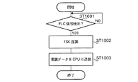
一方、電化製品(テレビ107)において、PLCユニット505は、図10に示すように、電源投入がされると、この招待信号が含まれる電灯線通信に用いられる周波数帯域の信号(以下、「PLC信号」という)の検出を監視している。この監視下において、PLC信号を検出したならば(ST1001)、PLCユニット505は、保有している変調方式であるFSK方式によりこのPLC信号を復調する(ST1002)。そして、復調したデータをCPU501に送信する(ST1003)。
【0073】
電化製品(テレビ107)のCPU501は、図11に示すように、PLCユニット505からデータ送信を監視している。この監視下において、PLCユニット505から復調されたデータを受信したならば(ST1101)、そのデータが適切に復調が行われているかを判断する(ST1102)。ここで、データの復調が適切に行われているかは、例えば、復調後のデータのフレームに付加されたCRCを検証することで判断する。
【0074】
適切に復調が行われているならば、この復調されたデータの宛先が自機宛てか判断する(ST1103)。具体的には、この復調されたデータのデータフレームに記述された相手先アドレスに自機(テレビ107)のアドレスが記述されているかを判断する。
【0075】
復調されたデータの宛先が自機宛てであるならば、この復調されたデータのフレームに記述されたデータタイプが初期登録であるか判断する(ST1104)。データタイプが初期登録であるかどうかを判断することにより、以前に管理装置100に対して応答信号を送信した電化製品が再び応答信号を送信するのを回避することができる。
【0076】
データタイプが初期登録であった場合には、CPU501は、応答信号を管理装置100に対して送信するようにPLCユニット505に指示し(ST1105)、処理を終了する。なお、この指示に応じて、PLCユニット505から管理装置100に応答信号が送信される。
【0077】
このように本管理装置100によれば、電灯線103に接続されている各電化製品に搭載されたモデムとして機能するPLCユニット505の変調方式が異なっていても、管理装置100が各電化製品に搭載されたモデムの変調方式を確認して登録する。これにより、この管理装置100が各電化製品に搭載されたモデムの変調方式に適合した制御を行うことが可能となるので、同一の変調方式のモデムを搭載した電化製品を買い揃えることなく、電灯線通信による家庭内の電化製品の制御を実現できる。
【0078】
また、本管理装置100によれば、各電化製品が搭載するモデムの変調方式を確認する旨の制御信号の送出を定期的に行う。これにより、各電化製品が搭載するモデムの変調方式の確認は定期的に行われるので、新規に購入した電化製品についても、その変調方式を自動的に登録して漏れることなく対応することができる。
【0079】
なお、本実施の形態では、各電化製品が搭載するモデムの変調方式を確認する旨の制御信号の送出を定期的に行う場合について説明しているが、これに限定されず、当該制御信号の送出を任意の操作により行なわれるようにしてもよい。この場合には、新規に電化製品を購入した場合、その時点で手動によりその電化製品が搭載したモデムの変調方式を登録できるので、定期的に確認を行う場合のように、新規の電化製品を設置してから自動的に確認動作が行われるまでの間に、その電化製品に対応できないという不都合を解消できる。
【0080】
次に、管理装置100が各電化製品から何らかの信号を受信した場合に、その信号を解析することで電化製品が有する変調方式等の情報を登録する場合について説明する。図12は、本実施の形態に係る管理装置100が各電化製品から何らかの信号を受信した場合に電化製品の変調方式等の情報を登録する場合の動作を説明するためのフロー図である。
【0081】
図12に示す動作は、例えば、新たな電化製品が電灯線103に接続され、当該電化製品が有する変調方式を管理装置100に通知するような場合に実行される。この際、当該電化製品は、発信元アドレス802に予め定められた仮アドレスを記述し、またデータタイプ804に変調方式等の初期登録の旨を記述したPLC信号を管理装置100に送信する。
【0082】
図12に示すように、待機状態において、管理装置100は、電灯線103上に接続された電化製品からのPLC信号を監視している。この状態において、いずれかの電化製品からPLC信号を受信したならば(ST1201)、このPLC信号の変調方式を判定する処理(以下、「変調方式判定処理」という)を行う(ST1202)。この変調方式判定処理は図13を用いて後述する。この変調方式判定処理により、受信したPLC信号の変調方式が検出される。
【0083】
PLC信号の変調方式を検出したならば、管理装置100は、当該PLC信号を復調する(ST1203)。そして、復調したデータのフレームの内容を解析する(ST1204)。この解析により、発信元アドレス802には仮アドレスが記述され、データタイプ804が初期登録であることが解析される。
【0084】
データフレームを解析した後、発信元の変調方式等の情報がメモリ202内の電化製品情報テーブル300に既に登録されているか判断する(ST1205)。なお、ST1204で解析されたデータタイプ804が初期登録の場合には、メモリ202内の電化製品情報テーブルに変調方式等の情報が未登録であると判断される。
【0085】
変調方式等の情報が未登録と判断された場合には、ST1202で検出した変調方式等の情報をメモリ202内の電化製品情報テーブル300に登録し(ST1206)、処理を終了する。一方、情報が既に登録されていると判断された場合には、登録処理を行わずに処理を終了する。
【0086】
ここで、ST1202における変調方式判定処理について説明する。図13は、本実施の形態に係る管理装置100における変調方式判定処理の動作について説明するためのフロー図である。なお、この変調方式判定処理は、管理装置100におけるマルチPLCユニット204の受信変調信号判定部413により行われる。
【0087】
図13に示すように、変調方式判定処理を行う場合、まず、管理装置100は、PLC信号の発信元の電化製品における変調方式を検出する(ST1301)。具体的には、受信したPLC信号のベースとなっている搬送波の変化点を検出することで、PLC信号の発信元の電化製品における変調方式を検出する。
【0088】
例えば、発信元の電化製品における変調方式がPSK変調の場合、PLC信号のベースとなっている搬送波は、その位相を変化させながら送出される。また、変調方式がFSK変調の場合、搬送波は、その周波数を変化させながら送出される。さらに、変調方式がASK変調の場合、搬送波は、その振幅を変化させながら送出される。管理装置100は、このようなPSK変調の場合における位相の変化点、FSK変調の場合における周波数の変化点、ASK変調の場合における振幅の変化点を検出することで、発信元の電化製品における変調方式を検出する。
【0089】
図14は、管理装置100において、発信元の電化製品における変調方式を検出する場合において、検出される各変調方式の変化点を示した図である。図14に示すように、PSK変調の場合には、点A1、点A2、点A3、点A4で位相の変化点が検出される。また、FSK変調の場合には、点B1、点B2、点B3、点B4、点B5、点B6、点B7、点B8で周波数の変化点が検出される。さらに、ASK変調の場合には、点C1、点C2で振幅の変化点が検出される。
【0090】
発信元の電化製品における変調方式を検出した後、管理装置100は、その変調方式がASK変調であるか(ST1302)、PSK変調であるか(ST1303)、FSK変調であるか(ST1304)を判断する。
【0091】
次に、それぞれの変調方式において検出された搬送波の変化点が出現する時間間隔に基づいてデータ伝送速度を検出し(ST1305〜ST1307)、ここで検出した変調方式及びデータ伝送速度をメモリ202の電化製品テーブル300に登録する(ST1308〜ST1310)。なお、変調方式の最後の判断工程に位置したFSK変調の判断において、FSK変調でないと判断された場合には、何らかのエラーが発生したとして処理をST1301に戻す。
【0092】
このように本管理装置100によれば、管理装置100が各電化製品に搭載されたモデムとして機能するPLCユニットの変調方式を登録していない場合であっても、電化製品から何らかの信号が送信されてきた場合、その信号に基づいて各電化製品に搭載されたモデムの変調方式を判断して登録する。これにより、電灯線103に接続されている各電化製品に搭載されたモデムの変調方式が異なっていても、管理装置100が各電化製品に搭載されたモデムの変調方式に適合した制御を行うことが可能となるので、同一の変調方式のモデムを搭載した電化製品を買い揃えることなく、電灯線通信による家庭内の電化製品の制御を実現できる。
【0093】
次に、本管理装置100が異なる変調方式を有する電化製品間の電灯線通信を制御する場合の具体例について説明する。図15は、本管理装置100が異なる変調方式を有する電化製品間の電灯線通信を制御する場合のシーケンス図である。
【0094】
図15においては、変調方式としてASK変調を行う冷蔵庫111とFSK変調を行うテレビ107との間の通信を制御する場合について示す。具体的には、冷蔵庫111からのアラームメッセージ又は確認メッセージをテレビ107の表示部504に表示する制御を行う場合について示す。なお、冷蔵庫111からアラームメッセージが送信される前段階において、冷蔵庫111及びテレビ107の変調方式等の情報は電化製品情報テーブル300に登録されているものとする。
【0095】
ここで、アラームメッセージは、所定時間、ドアが開いた状態である場合に出力されるメッセージであるものとし、確認メッセージは、所定時間開いた状態であったドアが閉じられた場合に出力されるメッセージであるものとする。
【0096】
冷蔵庫111において、所定時間の間、ドアが開いた状態であることを検知すると、冷蔵庫111からその旨を示すアラームメッセージが管理装置100に出力される(ST1501)。このとき、アラームメッセージには、冷蔵庫111が有する変調方式であるASK変調方式により変調処理が施されている。
【0097】
管理装置100は、このASK変調されたアラームメッセージを解析した後、出力先であるテレビ107が有する変調方式であるFSK変調方式により変調処理を施し、テレビ107に出力する(ST1502)。テレビ107では、このアラームメッセージを解析し、表示部504に当該アラームメッセージを表示する。
【0098】
ここで、冷蔵庫111のドアが閉められたものとする(ST1503)。この場合、冷蔵庫111からその旨を示す確認メッセージが管理装置100に出力される(ST1504)。このとき、確認メッセージには、冷蔵庫111が有する変調方式であるASK変調方式により変調処理が施されている。
【0099】
管理装置100は、このASK変調された確認メッセージを解析した後、出力先であるテレビ107が有する変調方式であるFSK変調方式により変調処理を施し、テレビ107に出力する(ST1505)。テレビ107では、この確認メッセージを解析し、表示部504に当該確認メッセージを表示する。
【0100】
図15に示したシーケンスにおける管理装置100及び電化製品の動作について説明する。図16及び図17は、図15に示したシーケンスにおける冷蔵庫111の動作を説明するためのフロー図である。図18は、図15に示したシーケンスにおける管理装置100の動作を説明するためのフロー図である。図19及び図20は、図15に示したシーケンスにおけるテレビ107の動作を説明するためのフロー図である。なお、図16は、冷蔵庫111において、所定時間の間、ドアが開いた状態を検出した場合の動作を示し、図17は、所定時間開いた状態であったドアが閉じられた状態を検出した場合の動作を示している。また、図19は、テレビ107のPLCユニット505の動作を示し、図20は、テレビ107のCPU501の動作を示している。
【0101】
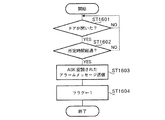
図16に示すように、冷蔵庫111は、ドアが開けられたかを常に監視している。この監視下において、ドアが開いたならば(ST1601)、その状態で所定時間が経過したかどうかを判断する(ST1602)。
【0102】
ドアが開いた状態で所定時間が経過しているならば、冷蔵庫111は、PLCユニットのASK変調部でドアが所定時間の間、開いた状態である旨のアラームメッセージにASK変調処理を施し、管理装置100に送信する(ST1603)。そして、ドアの所定時間の開放状態を示すフラグ(以下、「開放状態フラグ」という)に”1”をセットし(ST1604)、処理を終了する。
【0103】
一方、図17に示すように、ドアが開けられた場合と同様に、冷蔵庫111は、ドアが閉じられたか否かも常に監視している。この監視下において、ドアが閉じられたならば(ST1701)、開放状態フラグに”1”がセットされているか否かを判断する(ST1702)。
【0104】
開放状態フラグに”1”がセットされているならば、冷蔵庫111は、PLCユニットのASK変調部でドアが閉じられた旨の確認メッセージを管理装置100に送信する(ST1703)。そして、開放状態フラグに”0”をセットし(ST1704)、処理を終了する。
【0105】
図18に示すように、待機状態において、管理装置100は、電灯線103上に接続された電化製品からのPLC信号を監視している。この状態において、いずれかの電化製品からPLC信号を受信したならば(ST1801)、このPLC信号の変調方式判定処理を行う(ST1802)。この変調方式判定処理は、図13で説明した処理と同様であるため、その説明を省略する。尚、この処理は、モデムの変調方式等の情報が既登録の場合、省略してもよい。
【0106】
PLC信号の変調方式を検出したならば、管理装置100は、当該PLC信号を復調する(ST1803)。そして、復調したデータのフレームの内容を解析する(ST1804)。この解析により、発信元アドレス802には冷蔵庫111に割り当てられたアドレス(図3に示す”0X0110”)が記述され、相手先アドレス803にはテレビ107に割り当てられたアドレス(図3に示す”0X0107”)が記述され、データタイプ804がアラームメッセージであることが解析される。
【0107】
データフレームを解析した後、解析された相手先アドレス803に指定されたアドレスに基づいて当該アラームメッセージの送信先(相手先)の情報が電化製品情報テーブル300に登録されているか否かを判断する(ST1805)。上述のように、電化製品情報テーブル300には、送信先であるテレビ107の変調方式等の情報が登録されている。
【0108】
送信先の情報が電化製品情報テーブル300に登録されているならば、電化製品情報テーブル300に登録された変調方式等の情報を参照する(ST1806)。電化製品情報テーブル300には、図3に示すように、テレビ107の変調方式として、FSKによる変調方式が登録されている。したがって、このFSKによる変調方式等の情報が本管理装置100により参照される。
【0109】
そして、本管理装置100は、電化製品情報テーブル300に登録された変調方式等の情報により、冷蔵庫111からのアラームメッセージに変調処理を施した後、変調後のアラームメッセージをテレビ107に送信する(ST1807)。すなわち、送信先であるテレビ107の変調方式に合わせてアラームメッセージにFSK変調を行った後、FSK変調後のアラームメッセージをテレビ107に送信する。
【0110】
なお、ST1805により電化製品情報テーブル300に送信先の変調方式等の情報が登録されていない場合には、本管理装置100は、図9で説明した、電灯線103に接続された電化製品の変調方式等の情報の登録処理を行う(ST1808)。そして、送信先であるテレビ107の変調方式等の情報を把握した後、この情報に基づいて冷蔵庫111から送信されたアラームメッセージに変調処理を施し、テレビ107に送信する。
【0111】
ここでは、冷蔵庫111からのアラームメッセージについてのみ説明しているが、図17で説明した冷蔵庫111からの確認メッセージも同様に処理される。すなわち、冷蔵庫111が有する変調方式で復調された後、テレビ107が有する変調方式で変調され、テレビ107に送信される。
【0112】
一方、テレビ107において、PLCユニット505は、図19に示すように、電源投入がされると、PLC信号の検出を監視している。この監視下において、PLC信号を検出したならば(ST1901)、PLCユニット505は、保有している変調方式であるFSK方式によりこのPLC信号を復調する(ST1902)。そして、復調したデータをCPU501に送信する(ST1903)。
【0113】
テレビ107のCPU501は、図20に示すように、PLCユニット505からデータ送信を監視している。この監視下において、PLCユニット505から復調されたデータを受信したならば(ST2001)、そのデータが適切に復調が行われているかを判断する(ST2002)。ここで、データの復調が適切に行われているかは、例えば、復調後のデータのフレームに付加されたCRCを検証することで判断する。
【0114】
適切に復調が行われているならば、テレビ107は、この復調データを表示部504に表示する(ST2003)。これにより、冷蔵庫111から送信されたアラームメッセージがテレビ107の表示部504に表示されることとなる。なお、ここでは、アラームメッセージをテレビ107の表示部504に表示する場合の動作について説明しているが、確認メッセージを受信し、表示部504に表示されているアラームメッセージを消去する場合にも、図20に示す同様の処理が行われる。
【0115】
このように本管理装置100によれば、電灯線103に接続されている各電化製品に搭載されたモデムとして機能するPLCユニットの変調方式が異なっていても、電化製品情報テーブル300に登録された各電化製品に搭載されたモデムの変調方式等の情報に基づいて第1電化製品(冷蔵庫111)が搭載したモデムの変調方式の制御信号と第2電化製品(テレビ107)が搭載したモデムの変調方式の制御信号とを変換して第1電化製品(冷蔵庫111)と第2電化製品(テレビ107)との間の通信を行う。上述の例でいえば、冷蔵庫111のドアが所定時間以上開いている旨をテレビ107の表示部504に表示させる。これにより、同一の変調方式のモデムを搭載した電化製品を買い揃えることなく、電灯線通信による家庭内の電化製品の制御を実現できる。
【0116】
なお、本実施の形態では、管理装置100を各電化製品から独立した形態とした場合について説明している。しかし、これに限定されず、電灯線103に接続されたいずれかの電化製品に本管理装置100の機能を搭載するようにしてもよい。この場合にも本実施の形態で説明したのと同様の効果を得ることができることは言うまでもない。また、管理装置100と本管理装置100の機能を搭載した電化製品とを並列に配置してもよい。例えば、管理装置100の機能を搭載した電化製品をサブ管理装置と位置付け、通信状況の変化により管理装置100のみでは他の電化製品と通信できなくなった場合に、管理装置100の機能を搭載した電化製品に、管理装置100と他の電化製品との間の中継機としての役割を果たさせることもできる。
【0117】
【発明の効果】
以上説明したように、本発明によれば、電灯線通信に用いるモデムの変調方式が統一されていない欧州においても、同一の変調方式のモデムを搭載した電化製品を買い揃えることなく、家庭内の全電化製品の制御を電灯線通信により行うことができる。
【図面の簡単な説明】
【図1】本発明の一実施の形態に係る管理装置が適用される家庭内ネットワークの構成を示すブロック図
【図2】上記実施の形態に係る管理装置の概略構成を示すブロック図
【図3】上記実施の形態に係る管理装置のメモリに格納される電化製品情報テーブルの一例を示す図
【図4】上記実施の形態に係る管理装置のマルチPLCユニットの構成を示すブロック図
【図5】上記実施の形態に係る管理装置と電灯線を介して接続された電化製品の概略構成を示すブロック図
【図6】上記実施の形態に係る管理装置と電灯線を介して接続された電化製品(テレビ)のPLCユニットの構成を示すブロック図
【図7】上記実施の形態に係る管理装置から各電化製品に対して変調方式を確認するための制御信号を送信し、応答信号を受信する場合のシーケンス図
【図8】上記実施の形態に係る管理装置と電化製品との間で交換されるデータのフレーム構造の模式図
【図9】図7に示したシーケンスにおける管理装置の動作を説明するためのフロー図
【図10】図7に示したシーケンスにおける電化製品の動作を説明するためのフロー図
【図11】図7に示したシーケンスにおける電化製品の動作を説明するためのフロー図
【図12】上記実施の形態に係る管理装置が各電化製品から何らかの信号を受信した場合に電化製品の変調方式等の情報を登録する場合の動作を説明するためのフロー図
【図13】上記実施の形態に係る管理装置における変調方式判定処理の動作について説明するためのフロー図
【図14】上記実施の形態に係る管理装置において、発信元の電化製品における変調方式を検出する場合において、検出される各変調方式の変化点を示した図
【図15】上記実施の形態に係る管理装置が異なる変調方式を有する電化製品間の電灯線通信を制御する場合のシーケンス図
【図16】図15に示したシーケンスにおける冷蔵庫の動作を説明するためのフロー図
【図17】図15に示したシーケンスにおける冷蔵庫の動作を説明するためのフロー図
【図18】図15に示したシーケンスにおける管理装置の動作を説明するためのフロー図
【図19】図15に示したシーケンスにおけるテレビの動作を説明するためのフロー図
【図20】図15に示したシーケンスにおけるテレビの動作を説明するためのフロー図
【符号の説明】
100 管理装置
101 電力会社
102 公衆回線網
103 電灯線
104,106,112 室内照明
105 エアコン
107,108 テレビ
109 洗濯機
110 電子レンジ
111 冷蔵庫
201,501 CPU
202,502 メモリ
204 マルチPLCユニット
300 電化製品情報テーブル
404 変調部
405 復調部
505 PLCユニット
604 FSK変調部
605 FSK復調部[0001]
BACKGROUND OF THE INVENTION
The present invention relates to a management apparatus for controlling an appliance by power line communication and a control method thereof.
[0002]
[Prior art]
2. Description of the Related Art Conventionally, there is a system for controlling household appliances in a home by power line communication. Power line communication is a communication mode in which a power line that supplies power to each electrical appliance is used as a communication medium. Each electric appliance installed in the home is equipped with a modem for power line communication, and a management device for centrally managing each electric appliance is provided, and various controls for each electric appliance are performed from this management device. For example, the management device can detect that the door of the refrigerator is open for a predetermined time or more, and display information on the fact on the television screen to call attention. Moreover, it can control so that the sum total of the power consumption of each electric appliance does not exceed contract power consumption (for example, refer patent document 1).
[0003]
[Patent Literature]
JP 2002-84658 A
[0004]
[Problems to be solved by the invention]
However, such conventional techniques have the following problems.
[0005]
In other words, there is no common international standard for power line communication, and the correspondence varies from country to country or region. In particular, due to the influence of leaked radio waves on the allocated frequency band in which power line communication is possible in each country or region, the voltage used for electrical appliances and the frequency band already used (for example, radio broadcasting), etc. International coordination has become difficult.
[0006]
In Japan, domestic standards for power line communication are standardized mainly by the industry organization ECHONET Consortium. On the other hand, in Europe, the frequency band used for power line communication is regulated, but the modulation method of the modem is determined. Not. Further, an access protocol (Carrier Sense Multiple-Access (CSMA)) for collision avoidance of different modulation schemes is defined in the frequency band called C band (125-140 kHz) in European Norm 50065-1. Therefore, it is possible to construct a system using various modulation methods as long as the CSMA protocol is observed.
[0007]
Specific modulation schemes include an ASK (Amplitude-Shift Keying) modulation scheme, an FSK (Frequency-Shift Keying) modulation scheme, and a PSK (Phase-Shift Keying) modulation scheme. Each modulation scheme has advantages and disadvantages.
[0008]
Each modulation system generally has the following characteristics. The ASK modulation method has an advantage that the circuit can be easily configured, but has a disadvantage of being vulnerable to noise. The PSK modulation method has an advantage of being resistant to noise, but has a disadvantage that the circuit configuration becomes complicated. The FSK system has an intermediate feature between the ASK modulation system and the PSK modulation system.
[0009]
Therefore, the modulation system of modems installed in European electrical appliances is not standardized, and even if you purchase an appliance with a power line communication function, you can not communicate with the power line between appliances with different modulation methods There was a problem.
[0010]
The present invention has been made in view of such problems, and purchases electric appliances equipped with modems of the same modulation method even in Europe where the modulation method of modems used for power line communication is not unified. It is another object of the present invention to provide a management apparatus and a control method thereof that can control all electrical appliances in the home by power line communication.
[0011]
[Means for Solving the Problems]
The present inventionA management apparatus for managing a device having a power line modem connected to a power line network, and using a first modulation method as a confirmation signal for confirming a modulation method used in the power line modem of the device A second modulation unit that modulates a confirmation signal for confirming a modulation method used in the power line modem of the device by using a second modulation method; Each of the confirmation signals modulated by the first modulation unit and the second modulation unit is transmitted to the power line network, a reception unit that receives a signal from the device, and the reception unit. A modulation method determination unit that determines a modulation method used in the power line modem of the device based on the presence or absence of a response to the confirmation signal, and a power line model of the device based on the determination result of the determination unit. Management device and a registration unit for registering a modulation scheme is usedIt is.
[0012]
According to the present invention,A confirmation signal for confirming the modulation method used by the power line modem of the device is sent to the power line network using a plurality of modulation methods, so a plurality of power line modems with different modulation methods are connected to the power line network. Even in this case, the modulation method used by the power line modem of each device can be registered. thereforeTherefore, it is possible to control home appliances through power line communication without purchasing appliances equipped with modems of the same modulation method.
[0013]
DETAILED DESCRIPTION OF THE INVENTION
FirstThe present invention is a management apparatus for managing a device having a power line modem connected to a power line network, wherein a confirmation signal for confirming a modulation method used in the power line modem of the device is a first signal. A first modulation unit that modulates using the modulation method, and a second modulation unit that modulates a confirmation signal for confirming the modulation method used in the power line modem of the device using the second modulation method A transmission unit that transmits each confirmation signal modulated by the first modulation unit and the second modulation unit to the power line network, a reception unit that receives a signal from the device, and the reception Based on the presence or absence of a response to each confirmation signal in the unit, a modulation method determination unit that determines a modulation method used in the power line modem of the device, and a result of the determination by the determination unit A registration unit for registering a modulation scheme lighting line modem is used, a management device provided with.
[0014]
According to this configuration,A confirmation signal for confirming the modulation method used by the power line modem of the device is sent to the power line network using a plurality of modulation methods, so a plurality of power line modems with different modulation methods are connected to the power line network. Even in this case, the modulation method used by the power line modem of each device can be registered. thereforeTherefore, it is possible to control home appliances through power line communication without purchasing appliances equipped with modems of the same modulation method.
[0015]
SecondThe invention of the transmitterButThe management device transmits the confirmation signal periodically or by any operation.
[0016]
According to this configuration, the modulation method of the modem installed in each appliance is checked regularly, so even newly purchased appliances can automatically register the modulation method without omission. can do.
[0017]
Also, if the modulation method of the modem installed in each electrical appliance is checked by an arbitrary operation rather than periodically, when a new electrical appliance is purchased, the modulation of the modem installed in that electrical appliance is manually performed at that time. Since the method can be registered, it is possible to eliminate the inconvenience of not being able to support the appliance after the new appliance has been installed and the confirmation operation is automatically performed, as in the case of checking periodically. .
[0018]
ThirdThe present invention is a management device for managing a device having a power line modem connected to a power line network, a receiving unit for receiving a signal transmitted from the power line modem of the device, and the characteristics of the carrier wave of the signal Based on the change point at which the power line modem of the device changes, the modulation method determination unit that determines the modulation method used by the power line modem of the device, and the power line modem of the device uses the result of determination by the determination unit And a registration unit for registering the modulation method.
[0019]
According to this configuration,When a device that is not recognized by the management device is connected to the power line network, it is used by the power line modem of the device based on the changing point where the characteristics of the carrier wave of the signal transmitted from the power line modem of the device changes. It is possible to determine the modulation methodit can.
[0020]
4thThe invention ofOf the third inventionThe management device is a management device in which the characteristic of the carrier wave is any one of the phase, amplitude, and frequency of the carrier wave.
[0021]
According to this configuration,When a device that is not recognized by the management device is connected to the power line network, based on the changing point where the phase, amplitude, or frequency of the carrier wave of the signal transmitted from the power line modem of the device changes, To determine the modulation scheme used by the wire modemit can.
[0022]
5thThe invention ofOf the first or second inventionIn the management apparatus, the first modulation unit and the second modulation unit may be any one of an ASK modulation method, an FSK modulation method, and a PSK modulation method as the first modulation method and the second modulation method. It is a management device using two.
[0023]
According to this configuration,Even if appliances equipped with ASK, FSK, and PSK modulation modems have different modulation methods, the management device is compatible with the modulation method of the modem installed in each appliance. Control can be performedTherefore, it is possible to realize control of electric appliances through power line communication without purchasing electric appliances equipped with modems of the same modulation method.
[0024]
6thThe invention ofOf any of the first, second and fifth inventionsThe management apparatus further includes a conversion unit that converts the first signal using the first modulation scheme into the second signal using the second modulation scheme.
[0025]
According to this configuration,It becomes possible to communicate between power line modems with different communication methods.
[0026]
7thThe invention ofOf the sixth inventionThe management device, wherein the power line network communicates with a first device having a first power line modem that communicates using the first modulation method, using the second modulation method. The receiving unit is configured to receive a first signal transmitted from the first power line modem and using the first modulation method, and the converting unit includes the first power line modem. The first signal using the first modulation method is converted into the second signal using the second modulation method, and the transmission unit transmits the second signal to the second power line modem. It is a management device.
According to this configuration, it is possible to perform communication between power line modems having different communication methods.
[0027]
8thThe invention ofOf the seventh inventionA management device, a refrigerator equipped with the first power line modem, and a television equipped with the second power line modem, and the refrigerator has a door opened for a predetermined time or more, A signal indicating that the door is open is transmitted via the first power line modem, and the management device changes the modulation method used for the signal from the first modulation method to the second modulation method. It is a power line communication system that converts the signal into a system and transmits the signal to the television, and the television displays an alarm message on the display unit of the television based on the signal.
According to this configuration, it is possible to perform communication between a refrigerator and a television having different modulation methods.
[0028]
9thThe present invention provides a management method for managing a device having a power line modem connected to a power line network, wherein a confirmation signal for confirming a modulation method used in the power line modem of the device is a first signal. Modulation is performed using a modulation scheme, and a confirmation signal for confirming the modulation scheme used in the power line modem of the device is modulated using a second modulation scheme, and the first modulation section and the second modulation section are modulated. Each confirmation signal modulated by the modulation unit is transmitted to the power line network, receives a signal from the device, and is used by the power line modem of the device based on whether there is a response to the confirmation signal. This is a management method for determining the modulation method used and registering the modulation method used by the power line modem of the device based on the determined result.
According to this configuration, since the confirmation signal for confirming the modulation method used in the power line modem of the device is transmitted to the power line network using the plurality of modulation methods, a plurality of different modulation methods are transmitted to the power line network. Even when a power line modem is connected, the modulation method used by the power line modem of each device can be registered. Therefore, it is possible to realize control of home appliances through power line communication without purchasing appliances equipped with modems of the same modulation method.
[0032]
Hereinafter, embodiments of the present invention will be described in detail with reference to the drawings.
[0033]
FIG. 1 is a block diagram showing a configuration of a home network to which a management apparatus according to an embodiment of the present invention is applied.
[0034]
As shown in FIG. 1, a
[0035]
The
[0036]
The
[0037]
The PLC unit provided in each electrical appliance functions as a modem that realizes communication by executing modulation / demodulation processing in a modulation scheme set in advance in each electrical appliance when performing communication using the
[0038]
FIG. 2 is a block diagram showing a schematic configuration of the
[0039]
As shown in the figure, a
[0040]
In addition, the memory 202 stores a table (hereinafter referred to as “electric appliance information table”) that is referred to when the
[0041]
FIG. 3 is a diagram illustrating an example of the electrical appliance information table stored in the memory 202 of the
[0042]
The electrical appliance table 300 includes a
[0043]
FIG. 4 is a block diagram showing a configuration of
[0044]
In the
[0045]
The
[0046]
The
[0047]
The
[0048]
The reception modulation
[0049]
FIG. 5 is a block diagram showing a schematic configuration of an electrical appliance connected to the
[0050]
As shown in the figure, the
[0051]
In this embodiment, a case where only the address of the
[0052]
FIG. 6 is a block diagram showing a configuration of the
[0053]
In the
[0054]
In addition, the
[0055]
The
[0056]
First, a case will be described in which a control signal for confirming a modulation scheme possessed by each electrical appliance is transmitted periodically or by an arbitrary operation, and information such as a modulation scheme possessed by each electrical appliance is registered by a response signal.
[0057]
FIG. 7 is a sequence diagram when a control signal for confirming a modulation method is transmitted to each electrical appliance from
[0058]
In this case, the
[0059]
Here, a frame structure of data exchanged between the
[0060]
As shown in FIG. 8, a frame of data exchanged between the
[0061]
When the invitation signal is transmitted from the
[0062]
As shown in FIG. 7, first,
[0063]
If there is no response to the ASK-modulated invitation signal sent for the third time even after a certain period of time has elapsed,
[0064]
If there is no response to the invitation signal that has been PSK modulated even after a certain period of time has elapsed,
[0065]
Upon receiving this response signal, the
[0066]
The
[0067]
Operations of the
[0068]
As shown in FIG. 9,
[0069]
On the other hand, if no response signal is received in ST902, it is determined whether this ASK-modulated invitation signal has been transmitted to the appliance three times (ST904). By determining whether or not the invitation signal has been transmitted three times in this way, it is possible to avoid malfunctioning in a situation where the response signal cannot be received. If the ASK-modulated invitation signal has not been transmitted three times, the process returns to ST901, and the processes so far are repeated.
[0070]
If the ASK-modulated invitation signal has been transmitted three times, the same processing as ST901 to ST904 is performed on the PSK-modulated invitation signal. That is, first, an invitation signal subjected to PSK modulation is transmitted to the electrical appliance (ST905), and it is determined whether a response signal is received within a certain time (ST906). When the response signal is received, it is assumed that the tele can respond to the invitation signal that is PSK modulated, and that the modulation method of the electrical appliance is PSK modulation is registered in the electrical appliance information table 300 in the memory 202 (ST907). ), The process is terminated. On the other hand, if a response signal is not received, it is determined whether this invitation signal modulated with PSK has been transmitted to the appliance three times (ST908). In the sequence shown in FIG. 7, since the modulation method of the
[0071]
If the PSK-modulated invitation signal is transmitted three times, this time, the same processing as ST901 to ST904 is performed on the FSK-modulated invitation signal. That is, first, the FSK-modulated invitation signal is transmitted to the electrical appliance (ST909), and it is determined whether a response signal is received within a certain time (ST910). When the response signal is received, it is assumed that the electrical appliance can respond to the FSK-modulated invitation signal, and the electrical appliance information table 300 in the memory 202 registers that the modulation method of the electrical appliance is FSK modulation ( ST911), the process ends. On the other hand, if no response signal is received, it is determined whether or not this FSK-modulated invitation signal has been transmitted to the appliance three times (ST912). If transmitted three times, the process ends. In the sequence illustrated in FIG. 7, since the modulation scheme of the
[0072]
On the other hand, in the electrical appliance (television 107), when the
[0073]
The
[0074]
If demodulation is performed appropriately, it is determined whether the destination of the demodulated data is addressed to the own device (ST1103). Specifically, it is determined whether the address of the own device (television 107) is described in the destination address described in the data frame of the demodulated data.
[0075]
If the destination of the demodulated data is addressed to its own device, it is determined whether the data type described in the demodulated data frame is initial registration (ST1104). By determining whether or not the data type is initial registration, it is possible to prevent the appliance that has previously transmitted the response signal to the
[0076]
If the data type is initial registration, the
[0077]
As described above, according to the
[0078]
Further, according to the
[0079]
Note that this embodiment describes the case where the control signal for confirming the modulation scheme of the modem mounted on each appliance is periodically transmitted, but the present invention is not limited to this, and the control signal The sending may be performed by an arbitrary operation. In this case, if you purchase a new appliance, you can manually register the modulation method of the modem installed in the appliance at that time, so you can install a new appliance as you regularly check. It is possible to eliminate the inconvenience of not being able to handle the electrical appliance between the installation and the automatic confirmation operation.
[0080]
Next, when the
[0081]
The operation illustrated in FIG. 12 is executed, for example, when a new electrical appliance is connected to the
[0082]
As illustrated in FIG. 12, in the standby state, the
[0083]
If the PLC signal modulation scheme is detected,
[0084]
After analyzing the data frame, it is determined whether information such as a modulation method of the transmission source is already registered in the electrical appliance information table 300 in the memory 202 (ST1205). If the
[0085]
If it is determined that the information such as the modulation method is not registered, the information such as the modulation method detected in ST1202 is registered in the electrical appliance information table 300 in the memory 202 (ST1206), and the process is terminated. On the other hand, if it is determined that the information has already been registered, the process ends without performing the registration process.
[0086]
Here, the modulation scheme determination process in ST1202 will be described. FIG. 13 is a flowchart for explaining the operation of the modulation scheme determination process in the
[0087]
As shown in FIG. 13, when performing modulation scheme determination processing, first,
[0088]
For example, when the modulation method in the electrical appliance of the transmission source is PSK modulation, the carrier wave that is the base of the PLC signal is transmitted while changing its phase. When the modulation method is FSK modulation, the carrier wave is transmitted while changing its frequency. Further, when the modulation method is ASK modulation, the carrier wave is transmitted while changing its amplitude. The
[0089]
FIG. 14 is a diagram illustrating a change point of each detected modulation method when the
[0090]
After detecting the modulation method in the electrical appliance of the transmission source,
[0091]
Next, the data transmission rate is detected based on the time interval at which the detected change point of the carrier wave appears in each modulation scheme (ST1305 to ST1307), and the detected modulation scheme and data transmission rate are electrified in the memory 202. Register in the product table 300 (ST1308 to ST1310). If it is determined that the FSK modulation is not performed in the determination of the FSK modulation located in the last determination step of the modulation scheme, the process returns to ST1301 because some error has occurred.
[0092]
Thus, according to the
[0093]
Next, a specific example in the case where the
[0094]
FIG. 15 shows a case where communication between the
[0095]
Here, the alarm message is a message that is output when the door is open for a predetermined time, and the confirmation message is output when the door that has been open for a predetermined time is closed. It shall be a message.
[0096]
When it is detected in
[0097]
After analyzing this ASK-modulated alarm message,
[0098]
Here, it is assumed that the door of the
[0099]
After analyzing this ASK-modulated confirmation message,
[0100]
Operations of the
[0101]
As shown in FIG. 16, the
[0102]
If the predetermined time has passed with the door opened, the
[0103]
On the other hand, as shown in FIG. 17, as in the case where the door is opened, the
[0104]
If “1” is set in the open state flag,
[0105]
As shown in FIG. 18, in the standby state, the
[0106]
If the PLC signal modulation scheme is detected,
[0107]
After analyzing the data frame, it is determined whether or not the information on the transmission destination (destination) of the alarm message is registered in the electrical appliance information table 300 based on the address specified in the analyzed
[0108]
If the destination information is registered in electrical appliance information table 300, the information such as the modulation method registered in electrical appliance information table 300 is referred to (ST1806). In the electrical appliance information table 300, as shown in FIG. 3, a modulation scheme by FSK is registered as a modulation scheme of the
[0109]
Then, the
[0110]
If information such as the modulation method of the transmission destination is not registered in the appliance information table 300 in ST1805, the
[0111]
Here, only the alarm message from the
[0112]
On the other hand, in the
[0113]
The
[0114]
If demodulation is performed appropriately,
[0115]
As described above, according to the
[0116]
In the present embodiment, a case is described in which the
[0117]
【The invention's effect】
As described above, according to the present invention, even in Europe where the modulation schemes of modems used for power line communication are not unified, it is not necessary to purchase electrical appliances equipped with modems of the same modulation scheme in the home. All electrical appliances can be controlled by power line communication.
[Brief description of the drawings]
FIG. 1 is a block diagram showing a configuration of a home network to which a management apparatus according to an embodiment of the present invention is applied.
FIG. 2 is a block diagram showing a schematic configuration of a management apparatus according to the embodiment.
FIG. 3 is a diagram showing an example of an appliance information table stored in the memory of the management apparatus according to the embodiment.
FIG. 4 is a block diagram showing a configuration of a multi PLC unit of the management apparatus according to the embodiment.
FIG. 5 is a block diagram showing a schematic configuration of an appliance connected to the management device according to the embodiment via a power line.
FIG. 6 is a block diagram showing a configuration of a PLC unit of an electric appliance (television) connected to the management apparatus according to the embodiment through a power line.
FIG. 7 is a sequence diagram in a case where a control signal for confirming a modulation method is transmitted to each electrical appliance from the management apparatus according to the embodiment and a response signal is received.
FIG. 8 is a schematic diagram of a frame structure of data exchanged between the management apparatus and the electrical appliance according to the embodiment.
9 is a flowchart for explaining the operation of the management apparatus in the sequence shown in FIG. 7;
FIG. 10 is a flowchart for explaining the operation of the electrical appliance in the sequence shown in FIG.
11 is a flowchart for explaining the operation of the appliance in the sequence shown in FIG.
FIG. 12 is a flowchart for explaining an operation in the case where the management apparatus according to the above embodiment registers information such as a modulation method of an electrical appliance when a signal is received from each electrical appliance;
FIG. 13 is a flowchart for explaining the operation of a modulation scheme determination process in the management apparatus according to the embodiment;
FIG. 14 is a diagram showing a change point of each modulation method detected in the case of detecting a modulation method in a transmission source appliance in the management device according to the embodiment;
FIG. 15 is a sequence diagram when the management apparatus according to the embodiment controls power line communication between appliances having different modulation methods;
FIG. 16 is a flowchart for explaining the operation of the refrigerator in the sequence shown in FIG.
FIG. 17 is a flowchart for explaining the operation of the refrigerator in the sequence shown in FIG.
FIG. 18 is a flowchart for explaining the operation of the management apparatus in the sequence shown in FIG. 15;
FIG. 19 is a flowchart for explaining television operation in the sequence shown in FIG. 15;
20 is a flowchart for explaining the operation of the television in the sequence shown in FIG.
[Explanation of symbols]
100 management device
101 Electric power company
102 Public network
103 power line
104, 106, 112 Interior lighting
105 air conditioner
107,108 TV
109 Washing machine
110 Microwave oven
111 refrigerator
201,501 CPU
202,502 memory
204 Multi PLC unit
300 Electronics information table
404 Modulator
405 Demodulator
505 PLC unit
604 FSK modulator
605 FSK demodulator
Claims (5)
当該機器の電灯線モデムで用いている変調方式を確認するための確認信号を、第1の変調方式を用いて変調する第1の変調部と、
当該機器の電灯線モデムで用いている変調方式を確認するための確認信号を、第2の変調方式を用いて変調する第2の変調部と、
前記第1の変調部および前記第2の変調部によって変調されたそれぞれの確認信号を、当該電灯線ネットワークに送信する送信部と、
当該機器からの信号を受信する受信部と、
前記受信部における、それぞれの確認信号に対する応答の有無に基づいて、当該機器の電灯線モデムで用いている変調方式を判定する変調方式判定部と、
前記判定部が判定した結果に基づいて、当該機器の電灯線モデムが用いている変調方式を登録する登録部と、
当該第1の変調方式を用いた第1の信号を当該第2の変調方式を用いた第2の信号に変換する変換部と、を備え、
当該電力線ネットワークは、当該第1の変調方式を用いて通信を行う第1の電灯線モデムを有する第1の機器と当該第2の変調方式を用いて通信を行う第2の電灯線モデムを有する第2の機器を含み、
前記受信部は、当該第1の電灯線モデムから送信され、当該第1の変調方式を用いた第1の信号を受信し、
前記変換部は、該第1の変調方式を用いた第1の信号を当該第2の変調方式を用いた第2の信号に変換し、
前記送信部は、当該第2の信号を当該第2の電灯線モデムに送信する管理装置。A management device for managing a device having a power line modem connected to a power line network,
A first modulation unit that modulates a confirmation signal for confirming a modulation method used in the power line modem of the device using the first modulation method;
A second modulation unit that modulates a confirmation signal for confirming the modulation method used in the power line modem of the device using the second modulation method;
A transmission unit for transmitting each confirmation signal modulated by the first modulation unit and the second modulation unit to the power line network;
A receiving unit for receiving a signal from the device;
Based on the presence or absence of a response to each confirmation signal in the reception unit, a modulation method determination unit that determines the modulation method used in the power line modem of the device,
Based on the result determined by the determination unit, a registration unit that registers the modulation method used by the power line modem of the device,
A conversion unit that converts the first signal using the first modulation scheme into a second signal using the second modulation scheme,
The power line network includes a first device having a first power line modem that performs communication using the first modulation method and a second power line modem that performs communication using the second modulation method. Including a second device,
The receiving unit receives a first signal transmitted from the first power line modem and using the first modulation method;
The conversion unit converts the first signal using the first modulation scheme into a second signal using the second modulation scheme,
The transmission unit is a management device that transmits the second signal to the second power line modem .
前記送信部は、当該確認信号を定期的または任意の操作によって送信する管理装置。The management device according to claim 1,
The transmission unit is a management device that transmits the confirmation signal periodically or by any operation.
前記第1の変調部および前記第2の変調部は、当該第1の変調方式および当該第2の変調方式として、ASK変調方式、FSK変調方式、PSK変調方式のいずれか二つを用いる管理装置。The management device according to claim 1 or 2, wherein
The first modulation unit and the second modulation unit use any two of the ASK modulation method, the FSK modulation method, and the PSK modulation method as the first modulation method and the second modulation method, respectively. .
前記第1の電灯線モデムを搭載した冷蔵庫と、
前記第2の電灯線モデムを搭載したテレビと、を備え、
前記冷蔵庫は、前記冷蔵庫のドアが所定時間以上開いている場合、当該ドアが開いている状態を示す信号を前記第1の電灯線モデム介して送信し、
前記管理装置は、当該信号に用いられている変調方式を当該第1の変調方式から当該第2の変調方式に変換し、当該信号を前記テレビへ送信し、前記テレビは、当該信号に基づいて、前記テレビの表示部にアラームメッセージを表示する電灯線通信システム。A management device according to claim 1 ;
A refrigerator equipped with the first power line modem;
A television equipped with the second power line modem;
When the refrigerator door is open for a predetermined time or more, the refrigerator transmits a signal indicating the open state of the refrigerator via the first power line modem,
The management apparatus converts the modulation scheme used for the signal from the first modulation scheme to the second modulation scheme, and transmits the signal to the television. The television is based on the signal. A power line communication system for displaying an alarm message on the display unit of the television.
当該機器の電灯線モデムで用いている変調方式を確認するための確認信号を、第1の変調方式を用いて変調し、
当該機器の電灯線モデムで用いている変調方式を確認するための確認信号を、第2の変調方式を用いて変調し、
前記第1の変調部および前記第2の変調部によって変調されたそれぞれの確認信号を、当該電灯線ネットワークに送信し、
当該機器からの信号を受信し、それぞれの確認信号に対する応答の有無に基づいて、当該機器の電灯線モデムで用いている変調方式を判定し、
判定した結果に基づいて、当該機器の電灯線モデムが用いている変調方式を登録し、
当該第1の変調方式を用いた第1の信号を当該第2の変調方式を用いた第2の信号に変換し、
当該電力線ネットワークは、当該第1の変調方式を用いて通信を行う第1の電灯線モデムを有する第1の機器と当該第2の変調方式を用いて通信を行う第2の電灯線モデムを有する第2の機器を含み、
当該第1の電灯線モデムから送信され、当該第1の変調方式を用いた第1の信号を受信し、
当該第1の変調方式を用いた第1の信号を当該第2の変調方式を用いた第2の信号に変換し、
当該第2の信号を当該第2の電灯線モデムに送信する管理方法。A management method for managing a device having a power line modem connected to a power line network,
A confirmation signal for confirming the modulation method used in the power line modem of the device is modulated using the first modulation method,
A confirmation signal for confirming the modulation method used in the power line modem of the device is modulated using the second modulation method,
Transmitting each confirmation signal modulated by the first modulation unit and the second modulation unit to the power line network;
Receiving a signal from the device, based on the presence or absence of a response to each confirmation signal, determine the modulation method used in the power line modem of the device,
Based on the determined result, register the modulation method used by the power line modem of the device ,
Converting the first signal using the first modulation scheme into a second signal using the second modulation scheme;
The power line network includes a first device having a first power line modem that performs communication using the first modulation method and a second power line modem that performs communication using the second modulation method. Including a second device,
A first signal transmitted from the first power line modem and receiving the first signal using the first modulation method;
Converting the first signal using the first modulation scheme into a second signal using the second modulation scheme;
A management method for transmitting the second signal to the second power line modem .
Priority Applications (3)
| Application Number | Priority Date | Filing Date | Title |
|---|---|---|---|
| JP2002367803A JP4473504B2 (en) | 2002-12-19 | 2002-12-19 | Management device for controlling appliances by power line communication and control method thereof |
| US10/682,973 US6975211B2 (en) | 2002-12-19 | 2003-10-14 | Control apparatus and control method for managing communications between multiple electrical appliances through a household power line network |
| EP03029077A EP1432099A3 (en) | 2002-12-19 | 2003-12-17 | Control apparatus and control method for managing communications between multiple electrical appliances through a household power line network |
Applications Claiming Priority (1)
| Application Number | Priority Date | Filing Date | Title |
|---|---|---|---|
| JP2002367803A JP4473504B2 (en) | 2002-12-19 | 2002-12-19 | Management device for controlling appliances by power line communication and control method thereof |
Publications (2)
| Publication Number | Publication Date |
|---|---|
| JP2004201065A JP2004201065A (en) | 2004-07-15 |
| JP4473504B2 true JP4473504B2 (en) | 2010-06-02 |
Family
ID=32376287
Family Applications (1)
| Application Number | Title | Priority Date | Filing Date |
|---|---|---|---|
| JP2002367803A Expired - Fee Related JP4473504B2 (en) | 2002-12-19 | 2002-12-19 | Management device for controlling appliances by power line communication and control method thereof |
Country Status (3)
| Country | Link |
|---|---|
| US (1) | US6975211B2 (en) |
| EP (1) | EP1432099A3 (en) |
| JP (1) | JP4473504B2 (en) |
Cited By (1)
| Publication number | Priority date | Publication date | Assignee | Title |
|---|---|---|---|---|
| KR101025789B1 (en) * | 2010-10-15 | 2011-04-04 | 한국전력공사 | Apparatus for data processing and method for preventing signal collision |
Families Citing this family (52)
| Publication number | Priority date | Publication date | Assignee | Title |
|---|---|---|---|---|
| US6480510B1 (en) | 1998-07-28 | 2002-11-12 | Serconet Ltd. | Local area network of serial intelligent cells |
| US6549616B1 (en) | 2000-03-20 | 2003-04-15 | Serconet Ltd. | Telephone outlet for implementing a local area network over telephone lines and a local area network using such outlets |
| US6842459B1 (en) | 2000-04-19 | 2005-01-11 | Serconet Ltd. | Network combining wired and non-wired segments |
| IL152824A (en) | 2002-11-13 | 2012-05-31 | Mosaid Technologies Inc | Addressable outlet and a network using same |
| US7154381B2 (en) * | 2003-05-23 | 2006-12-26 | Sonos, Inc. | System and method for operating a sensed power device over data wiring |
| US8090857B2 (en) | 2003-11-24 | 2012-01-03 | Qualcomm Atheros, Inc. | Medium access control layer that encapsulates data from a plurality of received data units into a plurality of independently transmittable blocks |
| IL160417A (en) | 2004-02-16 | 2011-04-28 | Mosaid Technologies Inc | Outlet add-on module |
| KR100600734B1 (en) * | 2004-02-25 | 2006-07-14 | 엘지전자 주식회사 | Home network server device and the control method of the same |
| US8024055B1 (en) | 2004-05-15 | 2011-09-20 | Sonos, Inc. | Method and system for controlling amplifiers |
| US7372831B2 (en) * | 2004-08-11 | 2008-05-13 | Lg Electronics Inc. | Packet transmission acknowledgement in wireless communication system |
| JP4543817B2 (en) * | 2004-08-13 | 2010-09-15 | パナソニック電工株式会社 | Power line carrier communication equipment |
| ES2255835B1 (en) * | 2004-09-15 | 2007-08-01 | Sociedad Europea De Redes Virtuales E Ingenieria Telematica S.L. | INTELLIGENT AND CONNECTED MODULAR CONTROL SYSTEM FOR DOMOTIC INSTALLATION. |
| US7183902B2 (en) * | 2004-09-30 | 2007-02-27 | Hewlett-Packard Development Company, L.P. | Very local area network (VLAN) |
| US7873058B2 (en) | 2004-11-08 | 2011-01-18 | Mosaid Technologies Incorporated | Outlet with analog signal adapter, a method for use thereof and a network using said outlet |
| US8737420B2 (en) * | 2005-07-27 | 2014-05-27 | Sigma Designs Israel S.D.I. Ltd. | Bandwidth management in a powerline network |
| US20070025266A1 (en) * | 2005-07-27 | 2007-02-01 | Neal Riedel | Communicating schedule and network information in a powerline network |
| US8553706B2 (en) * | 2005-07-27 | 2013-10-08 | Coppergate Communications Ltd. | Flexible scheduling of resources in a noisy environment |
| US8175190B2 (en) | 2005-07-27 | 2012-05-08 | Qualcomm Atheros, Inc. | Managing spectra of modulated signals in a communication network |
| JP4525569B2 (en) * | 2005-11-21 | 2010-08-18 | トヨタ自動車株式会社 | Communication device |
| DE102006015840A1 (en) * | 2006-04-03 | 2007-10-04 | Miele & Cie. Kg | Operation and display device for e.g. stove, has operating handle for selecting operating programs, parameters and/or display options of household devices, which are displayed on display region of display indicator as summarized information |
| JP4527684B2 (en) * | 2006-05-16 | 2010-08-18 | 三菱電機株式会社 | Communication apparatus and communication system |
| JP4811253B2 (en) * | 2006-12-01 | 2011-11-09 | 船井電機株式会社 | Power line carrier communication system |
| JP5059128B2 (en) | 2007-01-25 | 2012-10-24 | トムソン ライセンシング | Satellite signal processing apparatus and antenna control apparatus |
| JP4416008B2 (en) * | 2007-05-18 | 2010-02-17 | ソニー株式会社 | Communication apparatus and communication method |
| KR100965701B1 (en) * | 2007-06-08 | 2010-06-24 | 파나소닉 전공 주식회사 | Power line communication system |
| WO2009006685A1 (en) * | 2007-07-09 | 2009-01-15 | Semitech Innovations Pty Ltd | Communication methods and devices |
| KR20090017826A (en) * | 2007-08-16 | 2009-02-19 | 엘지전자 주식회사 | Total laundry treating system |
| JP5205605B2 (en) * | 2008-10-03 | 2013-06-05 | ネッツエスアイ東洋株式会社 | Power line carrier communication equipment |
| JP5156920B2 (en) * | 2008-10-03 | 2013-03-06 | ネッツエスアイ東洋株式会社 | Power line carrier communication equipment |
| KR101563487B1 (en) * | 2009-05-11 | 2015-10-27 | 엘지전자 주식회사 | Portable terminal controlling home appliance |
| WO2010131305A1 (en) | 2009-05-15 | 2010-11-18 | パナソニック株式会社 | Electric power line communication apparatus and electric power line communication system |
| US20110005258A1 (en) * | 2009-07-09 | 2011-01-13 | Mathieu Audet | Method and system for managing appliance equipments |
| CN102025398B (en) * | 2009-09-11 | 2014-07-23 | 中颖电子股份有限公司 | Wired carrier communication method and device |
| CN102195677B (en) * | 2010-03-10 | 2014-03-12 | 青岛东软载波科技股份有限公司 | Receiving circuit, transmitting circuit, microcontroller and power-line carrier communication method |
| US8681619B2 (en) * | 2010-04-08 | 2014-03-25 | Landis+Gyr Technologies, Llc | Dynamic modulation selection |
| CN101834634B (en) * | 2010-04-16 | 2016-05-18 | 龚黎 | FSK and PSK Double-mode multifrequency power line carrier wave modem |
| JP5202572B2 (en) * | 2010-05-07 | 2013-06-05 | 三菱電機株式会社 | Air conditioner and air conditioner system |
| JP2012129809A (en) * | 2010-12-15 | 2012-07-05 | Enecyber Inc | Data transmission device using electric power line |
| US8760874B2 (en) * | 2011-09-01 | 2014-06-24 | Daniel P. Casey | Electrical box safety redesign |
| CN104204821B (en) * | 2012-04-09 | 2017-02-22 | 英派尔科技开发有限公司 | Smart appliance registration |
| CN102769591B (en) * | 2012-06-21 | 2015-04-08 | 天地融科技股份有限公司 | Self-adaptive method, self-adaptive system and self-adaptive device for audio communication modulation modes and electronic signature implement |
| US9244516B2 (en) | 2013-09-30 | 2016-01-26 | Sonos, Inc. | Media playback system using standby mode in a mesh network |
| US10571869B2 (en) * | 2014-10-29 | 2020-02-25 | Xiaomi Inc. | Systems for mode switching in an appliance |
| WO2016084225A1 (en) * | 2014-11-28 | 2016-06-02 | 三菱電機株式会社 | Control apparatus, communication system, communication method, and program |
| CN105573282B (en) * | 2016-02-03 | 2020-03-17 | 京东方科技集团股份有限公司 | Household power grid |
| JP6772048B2 (en) * | 2016-12-14 | 2020-10-21 | ルネサスエレクトロニクス株式会社 | Rate judgment device, rate judgment method and receiver |
| JP6419250B2 (en) * | 2017-04-12 | 2018-11-07 | 三菱電機株式会社 | Control device, communication system, communication method, and program |
| CN112489340A (en) * | 2019-09-12 | 2021-03-12 | 华为技术有限公司 | Fire-fighting terminal, fire-fighting control terminal and fire-fighting method |
| WO2021107961A1 (en) * | 2019-11-29 | 2021-06-03 | Focus Universal | System and method for power line communication |
| CN111917514B (en) | 2020-07-29 | 2023-05-19 | 天地融科技股份有限公司 | Data transmission method and device |
| CN112365701A (en) * | 2020-10-27 | 2021-02-12 | 广东电网有限责任公司广州供电局 | Ammeter data acquisition method, device, equipment and storage medium |
| US11683875B2 (en) * | 2021-05-19 | 2023-06-20 | Focus Universal Inc. | Power line communication to control lighting |
Family Cites Families (23)
| Publication number | Priority date | Publication date | Assignee | Title |
|---|---|---|---|---|
| US4429299A (en) * | 1979-01-05 | 1984-01-31 | Robertshaw Controls Company | Two-way AC power line communications system |
| US4580276A (en) * | 1983-08-05 | 1986-04-01 | Consultant's Choice Inc. | System and method for transporting data |
| US5818603A (en) * | 1996-03-29 | 1998-10-06 | Ricoh Company, Ltd. | Method and system for controlling and communicating with machines using multiple communication formats |
| US5084903A (en) * | 1989-02-28 | 1992-01-28 | First Pacific Networks | Modulation and demodulation system employing AM-PSK and QPSK communication system using digital signals |
| US6104707A (en) * | 1989-04-28 | 2000-08-15 | Videocom, Inc. | Transformer coupler for communication over various lines |
| FR2678084B1 (en) * | 1991-06-24 | 1993-09-24 | Sgs Thomson Microelectronics | METHOD FOR COMMUNICATING INFORMATION AND CONTROLS WITHIN A HOUSE OR A BUILDING, SYSTEM FOR IMPLEMENTING SAME, AND APPLICATION OF THIS SYSTEM TO A HOME AUTOMATION. |
| FR2736780B1 (en) * | 1995-07-13 | 1997-09-26 | Sgs Thomson Microelectronics | CIRCUIT FOR THE ASSIGNMENT OF A TRANSMISSION CHANNEL ON THE ELECTRICAL NETWORK |
| GB2305074A (en) * | 1995-08-31 | 1997-03-26 | Id Systems Ltd | Apparatus for Remotely Reading Data Storage Devices |
| JPH09186635A (en) * | 1995-12-29 | 1997-07-15 | Kokusai Electric Co Ltd | Equalizer |
| US5805053A (en) * | 1996-10-21 | 1998-09-08 | Elcom Technologies, Inc. | Appliance adapted for power line communications |
| US6175860B1 (en) * | 1997-11-26 | 2001-01-16 | International Business Machines Corporation | Method and apparatus for an automatic multi-rate wireless/wired computer network |
| JP3279277B2 (en) * | 1999-02-19 | 2002-04-30 | 三菱電機株式会社 | Multi-carrier communication method and multi-carrier communication device |
| JP2001197249A (en) * | 2000-01-17 | 2001-07-19 | Canon Inc | Facsimile equipment and its communicating method |
| CA2400556A1 (en) * | 2000-03-24 | 2001-10-04 | Icebox, Llc | Multimode apparatus with communication and control features |
| US6854059B2 (en) * | 2000-06-07 | 2005-02-08 | Conexant Systems, Inc. | Method and apparatus for medium access control in powerline communication network systems |
| JP2002051069A (en) * | 2000-08-07 | 2002-02-15 | Nippon Telegr & Teleph Corp <Ntt> | Gateway device |
| JP2002084658A (en) | 2000-09-07 | 2002-03-22 | Alps Electric Co Ltd | Domestic network system |
| JP3679320B2 (en) * | 2000-10-18 | 2005-08-03 | 三菱電機株式会社 | Power line carrier communication equipment |
| US20020095662A1 (en) * | 2000-10-25 | 2002-07-18 | Ashlock Robert L. | Utilizing powerline networking as a general purpose transport for a variety of signals |
| JP2002342724A (en) * | 2001-05-18 | 2002-11-29 | Nippon Signal Co Ltd:The | Reader-writer for non-contact ic card |
| JP4664524B2 (en) * | 2001-05-21 | 2011-04-06 | 株式会社東芝 | Home network system |
| US6879806B2 (en) * | 2001-06-01 | 2005-04-12 | Zensys A/S | System and a method for building routing tables and for routing signals in an automation system |
| US7049939B2 (en) * | 2002-07-31 | 2006-05-23 | Matsushita Electric Industrial Co., Ltd | Power line carrier system |
-
2002
- 2002-12-19 JP JP2002367803A patent/JP4473504B2/en not_active Expired - Fee Related
-
2003
- 2003-10-14 US US10/682,973 patent/US6975211B2/en not_active Expired - Fee Related
- 2003-12-17 EP EP03029077A patent/EP1432099A3/en not_active Withdrawn
Cited By (2)
| Publication number | Priority date | Publication date | Assignee | Title |
|---|---|---|---|---|
| KR101025789B1 (en) * | 2010-10-15 | 2011-04-04 | 한국전력공사 | Apparatus for data processing and method for preventing signal collision |
| WO2012050373A1 (en) * | 2010-10-15 | 2012-04-19 | 한국전력공사 | Remote meter-reading system and a signal-collision preventing method |
Also Published As
| Publication number | Publication date |
|---|---|
| EP1432099A3 (en) | 2005-11-02 |
| US6975211B2 (en) | 2005-12-13 |
| EP1432099A2 (en) | 2004-06-23 |
| US20040122531A1 (en) | 2004-06-24 |
| JP2004201065A (en) | 2004-07-15 |
Similar Documents
| Publication | Publication Date | Title |
|---|---|---|
| JP4473504B2 (en) | Management device for controlling appliances by power line communication and control method thereof | |
| JP4849972B2 (en) | Communication device, communication system, image acquisition device, moving image acquisition device, and setting method thereof | |
| US7626489B2 (en) | Power line communications device and method | |
| US7729375B2 (en) | Power line communication apparatus and data relay method | |
| US7224272B2 (en) | Power line repeater system and method | |
| US7558206B2 (en) | Power line communication rate limiting system and method | |
| KR100935367B1 (en) | A home gateway device | |
| US20060071776A1 (en) | Power line communication system with automated meter reading | |
| US20050220004A1 (en) | Repeater for power line communication system | |
| WO2012114421A1 (en) | Air conditioning apparatus and air conditioning system | |
| CN102520695B (en) | Electric vehicle remote control system and electric vehicle state reporting, controlling and querying method | |
| DK2426867T3 (en) | Interface device for a måleanordnings network | |
| KR20010083853A (en) | Automatic meter reading system comprising with power line communication apparatus using spread spectrum | |
| JP3011677B2 (en) | Information transfer device and information transmission system | |
| JP6180851B2 (en) | Automatic meter reading system | |
| CN211908840U (en) | Internet of things gateway device based on set top box | |
| KR100631796B1 (en) | Home Network System and Learning Method Using Learning Remote Control Repeater | |
| WO2011118227A1 (en) | Wireless remote control signal transmitter and wireless remote control signal receiver | |
| JP3633857B2 (en) | Method and apparatus for power line communication | |
| JP2004218848A (en) | Remote controller communication system for housing equipment and instrument | |
| KR200353093Y1 (en) | An intelligent meter gateway for processing communication between multi communication apparatuses and a high speed power line communication system using the same | |
| KR20050092161A (en) | An intelligent meter gateway for processing communication between multi communication apparatuses and a high speed power line communication system using the same | |
| KR20060115113A (en) | Home-gateway with power control function | |
| KR101100183B1 (en) | Remote controlling system of electric home appliances | |
| KR200375073Y1 (en) | Modem case for home network |
Legal Events
| Date | Code | Title | Description |
|---|---|---|---|
| A621 | Written request for application examination |
Free format text: JAPANESE INTERMEDIATE CODE: A621 Effective date: 20051219 |
|
| A977 | Report on retrieval |
Free format text: JAPANESE INTERMEDIATE CODE: A971007 Effective date: 20080314 |
|
| A131 | Notification of reasons for refusal |
Free format text: JAPANESE INTERMEDIATE CODE: A131 Effective date: 20080325 |
|
| A521 | Written amendment |
Free format text: JAPANESE INTERMEDIATE CODE: A523 Effective date: 20080523 |
|
| A131 | Notification of reasons for refusal |
Free format text: JAPANESE INTERMEDIATE CODE: A131 Effective date: 20090512 |
|
| A521 | Written amendment |
Free format text: JAPANESE INTERMEDIATE CODE: A523 Effective date: 20090702 |
|
| TRDD | Decision of grant or rejection written | ||
| A01 | Written decision to grant a patent or to grant a registration (utility model) |
Free format text: JAPANESE INTERMEDIATE CODE: A01 Effective date: 20100209 |
|
| A01 | Written decision to grant a patent or to grant a registration (utility model) |
Free format text: JAPANESE INTERMEDIATE CODE: A01 |
|
| A61 | First payment of annual fees (during grant procedure) |
Free format text: JAPANESE INTERMEDIATE CODE: A61 Effective date: 20100305 |
|
| FPAY | Renewal fee payment (event date is renewal date of database) |
Free format text: PAYMENT UNTIL: 20130312 Year of fee payment: 3 |
|
| R150 | Certificate of patent or registration of utility model |
Free format text: JAPANESE INTERMEDIATE CODE: R150 |
|
| FPAY | Renewal fee payment (event date is renewal date of database) |
Free format text: PAYMENT UNTIL: 20130312 Year of fee payment: 3 |
|
| FPAY | Renewal fee payment (event date is renewal date of database) |
Free format text: PAYMENT UNTIL: 20140312 Year of fee payment: 4 |
|
| R250 | Receipt of annual fees |
Free format text: JAPANESE INTERMEDIATE CODE: R250 |
|
| LAPS | Cancellation because of no payment of annual fees |