JP4472830B2 - Image forming apparatus - Google Patents
Image forming apparatus Download PDFInfo
- Publication number
- JP4472830B2 JP4472830B2 JP2000075220A JP2000075220A JP4472830B2 JP 4472830 B2 JP4472830 B2 JP 4472830B2 JP 2000075220 A JP2000075220 A JP 2000075220A JP 2000075220 A JP2000075220 A JP 2000075220A JP 4472830 B2 JP4472830 B2 JP 4472830B2
- Authority
- JP
- Japan
- Prior art keywords
- paper
- cassette
- paper feed
- lock
- user
- Prior art date
- Legal status (The legal status is an assumption and is not a legal conclusion. Google has not performed a legal analysis and makes no representation as to the accuracy of the status listed.)
- Expired - Fee Related
Links
Images


Landscapes
- Control Or Security For Electrophotography (AREA)
- Sheets, Magazines, And Separation Thereof (AREA)
Description
【0001】
【発明の属する技術分野】
本発明は、複写機等の画像形成装置、特に、その用紙管理機能に係る部分に関する。
【0002】
【従来の技術】
複写機等の画像形成装置では、通常の白色の用紙(以下「通常用紙」という)を使う場合だけでなく、白以外の色の用紙(以下「色紙」という)、社章やマークが入った特別の用紙、あるいは上質紙または特殊サイズ用紙等を使う場合がある(以下ではこれらを「特殊用紙」と総称する)。このような場合、特殊用紙を、通常用紙がセットされた給紙カセットとは別の給紙カセットに予めセットしておき、一定の限定された用途の場合にのみ、特殊用紙がセットされた給紙カセットから給紙し、画像形成を行うという使い方がされるのが一般的である。また、画像形成状態の確認のためなどに、片面のみ画像形成した後に不要となった用紙(以下「裏紙」という)の裏面に画像形成するため、裏紙だけを通常用紙とは別の給紙カセットにセットしておく場合もある。
【0003】
給紙カセットに用紙を補給する場合、あるいは給紙カセットにセットされている用紙を取り出す場合は、ユーザが手動で給紙カセットを引き出すか、あるいは取出スイッチを押すことによって給紙カセットを本体から引き出すものが一般的である。通常の複写機は、本体に収納されている給紙カセットを誰でも引き出してセットされている用紙を取り出したり、無くなった用紙を補給するすことが出来る。
【0004】
【発明が解決しようとする課題】
このように給紙カセット内の用紙を誰もが取り出せるようにしておくと、特殊用紙がセットされるべき給紙カセットに通常用紙がセットされたり、通常用紙がセットされるべき給紙カセットに特殊用紙がセットされてしまうことがある。また、通常用紙専用の給紙カセットの用紙がなくなった等の理由で、裏紙を給紙カセットから取り出して余分に通常用紙専用給紙カセットに移し替えて使用することも可能であり、この場合、次に使うユーザが両面モードを選択して画像形成を行うと、既に一度画像形成された面に重ねて画像形成してしまうことがある。このため、ユーザは、画像形成装置を使用するたびに、常に選択した給紙カセットに自分の希望する用紙が入っているかどうかを確認しなければならない。
【0005】
さらに、コンビニエンスストアなどに設置されている複写機のように、ユーザがセルフサービスで複写操作を行うようにしてある場合には、不特定多数のユーザが給紙カセットを引き出して用紙を容易に抜き出せるため、用紙の盗難が懸念される。
【0006】
本発明は、このような技術的背景のもとになされたものである。すなわち、その目的は、給紙カセットにセットされている各種用紙の管理を容易にし、意図しない用紙による画像形成や用紙の盗難などを有効に防止できる画像形成装置を提供することである。
【0007】
【課題を解決するための手段】
上記の目的を達成するために、請求項1記載の発明は、一又は二以上の給紙カセットを装着できる画像形成装置において、前記給紙カセットのそれぞれに設けられた、スタンバイ状態では前記給紙カセットをロックして引き出すことができないロック状態とするロック手段と、操作するユーザを画像形成装置が識別するために、ユーザが暗証番号を入力する操作部と、前記暗証番号毎にどの前記給紙カセットの前記ロック手段のロックをロック解除可能状態とし、どの前記給紙カセットの前記ロック手段のロックをロック解除不可状態とするかを示すロック解除情報を設定するためのロック制御手段と、を有し、 前記ロック制御手段は、ユーザが操作部から入力した前記暗証番号に基づいて、その暗証番号に対応する前記ロック解除情報を読み出して、そのロック解除情報に従って前記給紙カセット毎に前記ロック手段のロックをロック解除可能状態或いはロック解除不可状態とすることを特徴とする。
【0013】
請求項2記載の発明は、一又は二以上の給紙カセットを装着でき、各給紙カセットに用紙の有無を監視する用紙検知手段が設けられた画像形成装置において、前記給紙カセットのそれぞれに設けられた、スタンバイ状態では前記給紙カセットをロックして引き出すことができないロック状態とするロック手段と、画像形成装置がユーザを識別するためにユーザが暗証番号を入力する操作部と、前記暗証番号毎にどの前記給紙カセットの前記ロック手段のロックをロック解除可能状態とし、どの前記給紙カセットの前記ロック手段のロックをロック解除不可状態とするかを示すロック解除情報を設定するためのロック制御手段とを有し、前記ロック制御手段は、前記給紙カセットの前記ロック手段のロックがロック解除不可状態であって前記用紙検知手段から用紙がなくなった旨の信号を受けたときは、ユーザが操作部から入力した前記暗証番号に基づいて、その暗証番号に対応する前記ロック解除情報を読み出して、読み出したロック解除情報に従って当該給紙カセットのロック手段のロックをロック解除可能状態或いはロック解除不可状態とすることを特徴とする。
【0015】
請求項3記載の発明は、請求項1又は2のうちいずれか一項記載の画像形成装置において、前記各給紙カセットごとに、その給紙カセットの前記ロック手段のロックがロック解除可能状態かロック解除不可状態かを表示する表示手段を有することを特徴とする。
【0016】
【発明の実施の形態】
以下に図面を参照して、本発明の実施の形態について説明する。
【0017】
図1は、本発明の画像形成装置を適用した複写機の外観を示した概略斜視図であり、図2は、同複写機の制御ブロック図である。
【0018】
図2に示すように、本実施形態の複写機には、用紙の搬送や給紙カセット内の用紙の有無を検知する各種センサからなるセンサ部1、ユーザが各種設定や複写開始の操作を行う操作部3、給紙カセットから用紙を供給する給紙部4、感光ドラムに静電潜像を形成しトナーで現像して用紙に転写するドラム部5、原稿を走査するスキャナ部6、給紙された用紙を複写機内で搬送する搬送部7、用紙に転写されたトナー像を定着させる定着部8、そして、複写機の各種動作の制御やユーザによる各種設定の管理などを司る制御部9が設けられている。さらに、本実施形態の複写機には、後述の給紙カセット保持機構(図3参照)のロックを解除するカセットロック解除部2が設けられている。
【0019】
本実施形態の複写機では、制御部9は、さらに、ロック制御、暗証番号によるユーザの識別、給紙カセットの選択の制御、画像形成モードの制御、カセットオープンスイッチ内蔵のLEDの点灯/消灯の制御などを行うが、これらの詳細については後述する。
【0020】
図1において、本体21の上部に設けられた操作部22(図2の操作部3に対応する)は、各種の設定や複写動作の開始指示などを行うためのものであり、ユーザは、この操作部22から、モード゛の設定、暗証番号の設定、暗証番号の入力、給紙カセットの選択等を行う。
【0021】
本体21の下部に設けられた4段の給紙カセット23、24、25、26は、複写機本体21に収納されている。各給紙カセットの前面右側には、LED内蔵のカセットオープンスイッチ23a、24a、25a、26aが設けられている。この四つの給紙カセットのうち23及び24は、ユーザがカセットオープンスイッチ23a、24aを押すことにより自由に引き出して、用紙を取り出したり、補給することができる。一方、給紙カセット25及び26については、本体21に収納されているときに、個別にロックされた状態になっている。このロックを解除しなければ、その給紙カセットを本体から引き出すことができず、したがって、その給紙カセットにセットされた用紙を取り出したり、別の種類の用紙と入れ替えることもできない。
【0022】
例えば給紙カセット25についてみると、この給紙カセット25がロック解除可能の状態では、カセットオープンスイッチ25aのLEDが点灯する。この状態では、カセットオープンスイッチ25aを押して給紙カセット25を引き出すことが可能である。一方、給紙カセット25のロック解除が不可の状態では、カセットオープンスイッチ25aのLEDは消灯する。この状態では、カセットオープンスイッチ25aを押しても給紙カセット25を引き出すことはできない。他の給紙カセット26についても同様である。
【0023】
本体21の上には、自動原稿送り装置29が設置されている。原稿が自動原稿送り装置29にセットされ、複写開始ボタンが押されると、原稿は自動的に原稿台ガラスへ送られ、スキャナ部6によって走査され、原稿の複写動作が行われる。その原稿についての複写動作が終了すると、原稿は自動的に原稿台ガラスから自動原稿送り装置29に戻される。
【0024】
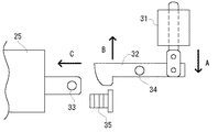
図3は、給紙カセット25の奥部に設けられた給紙カセット保持機構を横から見た側面図である。給紙カセット26にも、同様の給紙カセット保持機構が設けられている。図3において、給紙カセット25が奥まで収納されているときは、給紙カセット25の奥部に設けられたカセット係合部33と、カセット保持部材32の左側先端に設けられたかぎ状係合部が係合しており、そのままでは給紙カセット25を前面方向(矢印Cの方向)へ引き出すことはできない。
【0025】
給紙カセット25がロック解除可能な状態のときに、ユーザがカセットオープンスイッチ25aを押すと、図3に示したカセットソレノイド31が一定期間オン状態となり、カセット保持部材32の右側部分を矢印Aで示す向きに押し下げる。その結果、カセット保持部材32はカセット保持部材軸34を支点として時計方向に回転し、カセット保持部材32の左側先端のかぎ状係合部は、矢印Bで示す上向きに移動して、カセット係合部33からはずれる。これと同時に、給紙カセット25は、バネ35によって前面方向(矢印Cの方向)に付勢され、カセットソレノイド31がオフになってもカセット保持部材32のかぎ状係合部がカセット係合部33に係合しない位置まで押し出される。これにより、ユーザは給紙カセット25を手前側に引き出して、用紙の補給等を行うことができるようになる。
【0026】
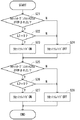
図4は、図1及び図3に示した複写機の給紙カセットのロック動作及びロック解除動作の制御を行うアルゴリズムを示したフローチャートである。なお、前述のように、給紙カセット23、24についてはユーザが自由に引き出すことができ、給紙カセット25、26については、ユーザが引き出すことが制限される。
【0027】
複写機に電源が投入され、あるいはユーザの複写動作が終了してスタンバイ状態になると、フラグL1及びL2には、ロックを解除できない状態であることを示す「0」が代入される(ステップ1)。ここで、フラグL1は給紙カセット25に対応し、フラグL2は給紙カセット26に対応する。続いて、暗証番号が既に設定されているかどうかを判定し(ステップ2)、暗証番号が設定されていない場合、あるいは別に新たな暗証番号を設定する場合は、管理者が例えば4桁の数字の組み合わせからなる暗証番号を設定する(ステップ3)。
【0028】
この暗証番号は、複数設定することが可能であり、それぞれの暗証番号ごとにロック解除情報が設定される。ここで「ロック解除情報」とは、どの給紙カセットをロック解除可能とし、どの給紙カセットをロック解除不可とするかを示す情報であり、具体的には内部フラグS1(給紙カセット25用)及びS2(給紙カセット26用)に対して設定される「0」又は「1」の情報である。このように複数の暗証番号の設定を可能とし、それぞれにロック解除情報を対応させたのは、使用を許可する給紙カセットをユーザごとに変えたい場合を考慮したものである。
【0029】
設定された暗証番号は、管理者が複写機の使用を許可する限られたユーザにのみ教えられ、ユーザがこの複写機を使用する場合には、操作部22から入力される暗証番号がここで設定された暗証番号と同じ場合にのみ、以後の操作が許される。
【0030】
暗証番号が既に設定されている場合には、ユーザが操作部22から暗証番号を入力するのを待つ状態となる。ユーザが暗証番号を入力すると(ステップ4)、その番号が予め設定されている暗証番号と一致するかどうかを判定する(ステップ5)。入力された暗証番号が予め設定されている暗証番号のどれかと一致した場合は、その暗証番号に対応するロック解除情報S1、S2が読み込まれ、L1、L2に代入される(ステップ6)。
【0031】
続いて、フラグL1、L2の値が「1」であるかどうかの判定が行われる(ステップ7、10)。フラグL1の値が「1」であれば、給紙カセット25がロック解除可能な状態となり、カセットオープンスイッチ25aのLEDを点灯させて、カセットオープンスイッチ25aを押すことにより給紙カセット25を引き出すことが可能であることを表示する(ステップ9)。一方、フラグL1の値が「0」であれば、給紙カセット25はロック解除不可状態となり、カセットオープンスイッチ25aのLEDを消灯して、カセットオープンスイッチ25aを押しても引き出せないことを表示する(ステップ8)。フラグL2についても同様である(ステップ10−12)。
【0032】
図5は、ロック解除動作を示すフローチャートである。まず、カセットオープンスイッチ25aが押されたかどうかを判定し(ステップ21)、カセットオープンスイッチ25aが押されたときは、フラグL1が「1」かどうかを判定する(ステップ22)。フラグL1が「1」であれば、給紙カセット25のカセットソレノイド31(図3参照)が一定時間オン状態となり(ステップ23)、カセット保持部材32の左側のかぎ状係合部材がカセット係合部33からはずれて、給紙カセット25がバネ35により手前側へ押し出される。フラグL1が「1」であれば、カセットソレノイド31はオフのままであり(ステップ24)、給紙カセット25のロックを解除することはできず、ユーザが給紙カセット25から用紙を取り出すことはできない。カセットオープンスイッチ26aが押された場合にも同様の処理がなされる(ステップ25−28)。
【0033】
以上のように、暗証番号を用いることによって権限のないユーザは給紙カセットのロックを解除できないようにし、また、権限のあるユーザでも、ロックを解除できる給紙カセットを制限できるようにすることにより、不用意な用紙の入れ替えによって目的としない用紙に画像形成してしまうことを防ぐことができる。
【0034】
これまでは、単純に、暗証番号によってある給紙カセットのロック解除を可能にしたり不可能にしたりするだけの制御だったが、この制御と、実際に複写の際に使用する給紙カセットの選択の可否を併せて制御することができる。
【0035】
複写機の画像形成モードには、通常モードの他に、カバーモード及び合紙モードがある。「カバーモード」とは、自動原稿送り装置を使って多数の原稿を一度に複写するときに、表紙と裏表紙だけは色紙などを使って複写するモードであり、「合紙モード」とは、多数の原稿を一度に複写するときに、例えば章の変わり目を分かり易くするために、各章の始めの用紙だけ合紙として色紙などを使うモードである。
【0036】
図6は、画像形成モードとしてカバーモードあるいは合紙モードが選択される場合に、選択できる給紙カセットを制限する制御を行うアルゴリズムを示したフローチャートである。ここでは、前提として、給紙カセット25には通常用紙がセットされ、給紙カセット26には、表紙、裏表紙、合紙などとして使用する色紙がセットされているものとする。ここで色紙は、表紙、裏表紙、合紙としては使用できるが、通常の複写には使用できないようにする。そのために、給紙カセット25用のフラグL1には「1」を、給紙カセット26用のフラグL2には「0」を設定する。なお、給紙カセット26用のフラグL2に「0」を設定することにより、給紙カセット26はロック解除不可状態となり、ユーザが管理者に無断で給紙カセット26を引き出すことはできない。
【0037】
複写開始ボタンが押されると、まず、画像形成モードとしてカバーモードが選択されているかどうかを判定し(ステップ41)、カバーモードが選択されている場合は、表紙及び裏表紙として使用する用紙がセットされている給紙カセットをユーザが選択する(ステップ42)。カバーモードが選択されていない場合は、合紙モードが選択されているかどうかを判定し(ステップ43)、合紙モードが選択されている場合は、合紙として使用する用紙がセットされている給紙カセットをユーザが選択する(ステップ44)。なお、ここで選択できる給紙カセットは、前述のL1、L2の値には関係なく、給紙カセット25、26のいずれをも選択することができる。すなわち、表紙等としては、色紙がセットされた給紙カセット26だけでなく、通常用紙がセットされた給紙カセット25を選択することも可能である。ただし、ここではユーザによって色紙がセットされた給紙カセット26が選択されたものとする。
【0038】
次に、通常の複写を行う給紙カセットを選択する。L1が「1」であれば給紙カセット25は通常の複写を行うための給紙カセットとして選択可能である。また、もし、L2が同じく「1」であれば給紙カセット26も通常の複写を行うための給紙カセットとして選択可能である。このため、ステップ45、ステップ48では、それぞれ給紙カセット25用のフラグL1、給紙カセット26用のフラグL2が「1」か否かの判定を行い、これらのフラグが1であれば、さらにそのカセットがユーザによって選択されたか否かの判定を行う(ステップ46、49)。しかし、前述のように、フラグL1には「1」を、フラグL2には「0」を設定してあるので、ステップ45の判定はYesであり、ステップ48の判定はNoである。このため、ユーザは、通常の複写を行うための給紙カセットとして給紙カセット26を選択することはできない。
【0039】
以上より、ユーザーが最初の設定でカバーモードを選択し、表紙及び裏表紙の複写を行うための給紙カセットとして給紙カセット26を選択し、通常の複写を行うための給紙カセットとして給紙カセット25を選択した場合は、1枚目の表紙の原稿の複写については給紙カセット26から色紙が給紙され、2枚目以降の原稿の複写については給紙カセット25から通常用紙が給紙され、そして最後の裏表紙の原稿の複写については再び給紙カセット26から色紙が給紙される。
【0040】
次に、給紙カセット内の用紙の有無と関連付けて行う給紙カセットのロック解除の制御について説明する。
【0041】
ある給紙カセット内の用紙がなくなると、給紙カセット内に設けられた用紙検知センサ(図2のセンサ部1に含まれる)がこれを検知し、操作部22のディスプレーにその旨を表示して、ユーザに対し紙の補給を促す。しかし、例えばある給紙カセットには通常用紙がセットされ、別の給紙カセットには高価な特殊用紙がセットされている場合には、通常用紙がなくなったからといって、権限のないユーザが勝手に特殊用紙がセットされた給紙カセットを引き出して用紙を取り出すことを禁止したい場合がある。また、給紙カセットの用紙がなくなったために一時的に裏紙をセットしたような場合に、残りの裏紙をそのままの状態にしておくと、次に使うユーザが、そうとは知らずに両面複写モードを選択して既に一度画像形成された面に重ねて画像形成してしまうこともある。
【0042】
そこで、所定の給紙カセットへのユーザによる用紙の補給を制限するために、次のような制御を行う。図7は、この制御のアルゴリズムを示したフローチャートである。まず、用紙が残っている給紙カセットについては常にロック状態とし(ステップ66、73)、その旨を表示するためにLEDを消灯する(ステップ67、74)。これにより、社章等が表示された重要な用紙や、上質紙等の高価な用紙を給紙カセットにセットしておいても、権限のない者がこれらを勝手に持ち出すことはできなくなる。
【0043】
図1に示した各給紙カセット23、24、25、26の内部には、用紙検知センサ(不図示)が設けられており、対応する給紙カセット内の用紙の有無を常に監視しているが、ここでは、給紙カセット25、26のみについて考える(ステップ61、68)。ここで、例えば給紙カセット25の用紙がなくなったことが検知されると、図4との関連で説明したように、使用時にユーザが入力した暗証番号に対応するロック解除情報S1がフラグL1に代入される(ステップ62)。このロック解除情報によって、給紙カセット25のユーザによるロック解除が可能であるかどうかが決定される。
【0044】
ここでフラグL1が「1」であるかどうかが判定され(ステップ63)、「1」である場合には、カセットオープンスイッチ25aに内蔵されたLEDを点灯して、その給紙カセットのロックをユーザが解除できるものである旨を表示する(ステップ64)。一方、フラグL1が「0」である場合には、給紙カセット25はロック解除不可状態となり、カセットオープンスイッチ25aのLEDを消灯して(ステップ65)、カセットオープンスイッチ25aを押しても引き出せない旨を表示する。給紙カセット26用のフラグL2についても同様の処理を行う(ステップ68−74)。
【0045】
この場合は、たとえ給紙カセット25の用紙がなくなった場合でも、ユーザは給紙カセット25のロック状態を解除して用紙を補給することはできず、必要があれば、管理者に給紙カセット25用の用紙の補給を依頼する。
【0046】
なお、本発明は上記実施の形態に限定されるものではなく、特許請求の範囲に記載した各請求項の要旨の範囲内で種々の変更が可能である。例えば、上記実施の形態では、本発明を複写機に適用した場合について説明したが、本発明は、複写機だけでなく、プリンタ、ファクシミリ、あるいはこれらが複合されたものなど、各種の画像形成装置に適用することができる。
【0047】
【発明の効果】
以上説明したように、本発明によれば、給紙カセットそれぞれにロック手段を設け、各給紙カセットごとにロック手段のロック状態又はロック解除状態の設定を可能としたことにより、ロックされた給紙カセットにセットされている例えば高価な特殊用紙などの紛失や盗難を有効に防止できる。
【0048】
また、ユーザ識別手段により識別される各ユーザごとに、各ロック手段のロック状態とロック解除状態を設定することにより、権限のない者はロックされた給紙カセットを引き出して用紙を取り出すことができなくなるため、用紙の管理が容易かつ確実となり、用紙の紛失や盗難を有効に防止できる。
【0049】
さらに、給紙カセット選択手段によってロックが解除されている給紙カセットのみをユーザが選択できるよう制御することにより、一定の給紙カセットについてはそれを引き出して用紙を取り出すことができないことに加え、権限のないユーザがその給紙カセットにセットされた用紙を使えないようにすることにより、用紙の管理がより徹底され、意図しない用紙に画像形成するといったミスや無駄な用紙の使用を防止することができる。
【0050】
また、カバーモードあるいは合紙モードでの連続画像形成機能を有する画像形成装置については、表紙、裏表紙、合紙のための特殊用紙がセットされた給紙カセットを、表紙等以外の画像形成の際に選択することを禁止することにより、特殊用紙などの用紙の管理が容易かつ確実となり、無駄な用紙の使用や紛失、盗難を有効に防止することができる。
【図面の簡単な説明】
【図1】本発明の画像形成装置を適用した複写機の外観を示した概略斜視図である。
【図2】本発明の画像形成装置を適用した複写機の制御ブロック図である。
【図3】給紙カセットの奥部に設けられた給紙カセット保持機構を横から見た側面図である。
【図4】給紙カセットのロック動作及びロック解除動作の制御を行うアルゴリズムを示したフローチャートである。
【図5】ロック解除動作を示すフローチャートである。
【図6】画像形成モードとしてカバーモードあるいは合紙モードが選択される場合に、選択できる給紙カセットを制限する制御を行うアルゴリズムを示したフローチャートである。
【図7】所定の給紙カセットへのユーザによる用紙の補給を制限するよう制御するアルゴリズムを示したフローチャートである。
【符号の説明】
1…センサ部 2…カセットロック解除部 3(22)…操作部 4…給紙部 5…ドラム部 6…スキャナ部 7…搬送部 8…定着部 9…制御部 21…本体 23、24、25、26…給紙カセット 23a、24a、25a、26a…カセットオープンスイッチ 29…自動原稿送り装置 31…カセットソレノイド 32…カセット保持部材 33…カセット係合部 34…カセット保持部材軸 35…バネ[0001]
BACKGROUND OF THE INVENTION
The present invention relates to an image forming apparatus such as a copying machine, and more particularly to a portion related to a paper management function thereof.
[0002]
[Prior art]
In image forming apparatuses such as copying machines, not only normal white paper (hereinafter referred to as “regular paper”) but also paper other than white (hereinafter referred to as “colored paper”), company emblems and marks entered In some cases, special paper, high-quality paper, special-size paper, or the like is used (hereinafter collectively referred to as “special paper”). In such a case, the special paper is set in a paper cassette different from the paper cassette in which the normal paper is set in advance, and the paper with the special paper set is used only for certain limited applications. In general, the paper is fed from a paper cassette to form an image. In addition, for the purpose of confirming the image formation status, etc., since only one side of the image is formed on the back side of paper that has become unnecessary (hereinafter referred to as “back paper”), only the back paper is fed separately from normal paper. It may be set in a paper cassette.
[0003]
When replenishing paper in the paper cassette or removing paper set in the paper cassette, the user manually pulls out the paper cassette or pulls out the paper cassette from the main unit by pressing the eject switch. Things are common. In a normal copying machine, anyone can pull out a paper cassette stored in the main body and take out the set paper, or replenish the lost paper.
[0004]
[Problems to be solved by the invention]
If anyone can take out the paper in the paper cassette in this way, normal paper can be set in the paper cassette where special paper should be set, or special paper can be set in the paper cassette where normal paper should be set. Paper may be loaded. It is also possible to remove the back paper from the paper cassette and transfer it to the normal paper cassette for use because the paper in the paper cassette dedicated to normal paper has run out. When the next user selects the double-side mode and forms an image, the image may be formed on the already formed surface. For this reason, every time the user uses the image forming apparatus, he or she must always check whether or not the desired paper is in the selected paper feed cassette.
[0005]
In addition, when users are allowed to perform self-service copying operations, such as copiers installed in convenience stores, an unspecified number of users can easily pull out the paper by pulling out the paper cassette. There is concern about theft of paper.
[0006]
The present invention has been made based on such a technical background. That is, an object of the present invention is to provide an image forming apparatus that facilitates management of various types of paper set in a paper feed cassette and can effectively prevent unintentional image formation and paper theft.
[0007]
[Means for Solving the Problems]
In order to achieve the above object, an invention according to
[0013]
According to a second aspect of the present invention, in the image forming apparatus in which one or two or more paper feed cassettes can be mounted, and each paper feed cassette is provided with paper detection means for monitoring the presence or absence of paper, each of the paper feed cassettes is provided. A locking unit provided in a locked state in which the paper feeding cassette cannot be locked and pulled out in a standby state ; an operation unit for a user to input a personal identification number so that the image forming apparatus can identify the user; and the personal identification number the locking of the locking means of which the sheet feeding cassette and an unlocked state for each number, for setting the unlock information indicating whether the locking of the locking means of which the sheet feeding cassette and unlocking disabled state and a lock control unit, the lock control means for the locking of the locking means of the paper feed cassette is a lock release disabled state The can and has received a signal indicating that there is no more paper from the detecting means, on the basis of the personal identification number input by the user from the operation unit reads the unlock information corresponding to the personal identification number, according to the read unlock information It is characterized in that the lock of the lock means of the paper feed cassette is set to the unlockable state or the unlockable state .
[0015]
According to a third aspect of the present invention, in the image forming apparatus according to any one of the first and second aspects, for each of the paper feed cassettes , is the lock of the lock means of the paper feed cassette in an unlockable state? It has a display means which displays whether it is a lock release impossible state, It is characterized by the above-mentioned.
[0016]
DETAILED DESCRIPTION OF THE INVENTION
Embodiments of the present invention will be described below with reference to the drawings.
[0017]
FIG. 1 is a schematic perspective view showing the appearance of a copying machine to which the image forming apparatus of the present invention is applied, and FIG. 2 is a control block diagram of the copying machine.
[0018]
As shown in FIG. 2, the copying machine according to the present embodiment includes a
[0019]
In the copier of this embodiment, the
[0020]
In FIG. 1, an operation unit 22 (corresponding to the
[0021]
Four stages of
[0022]
For example, regarding the
[0023]
An
[0024]
FIG. 3 is a side view of the paper feed cassette holding mechanism provided at the back of the
[0025]
When the user presses the cassette
[0026]
FIG. 4 is a flowchart showing an algorithm for controlling the locking operation and the unlocking operation of the paper feeding cassette of the copying machine shown in FIGS. As described above, the user can freely draw out the
[0027]
When power is turned on to the copying machine or when the user's copying operation is completed and the standby state is entered, "0" indicating that the lock cannot be released is substituted for the flags L1 and L2 (step 1). . Here, the
[0028]
A plurality of passwords can be set, and unlock information is set for each password. Here, the “unlock information” is information indicating which paper cassette can be unlocked and which paper cassette cannot be unlocked. Specifically, the internal flag S1 (for paper cassette 25) is used. ) And S2 (for the paper feed cassette 26), the information is “0” or “1”. In this way, a plurality of passwords can be set, and the unlock information is associated with each case in consideration of the case where it is desired to change the sheet cassette to be used for each user.
[0029]
The set personal identification number is taught only to a limited user whose administrator permits the use of the copying machine. When the user uses this copying machine, the personal identification number input from the
[0030]
If the password has already been set, the system waits for the user to input the password from the
[0031]
Subsequently, it is determined whether or not the values of the flags L1 and L2 are “1” (steps 7 and 10). If the value of the flag L1 is “1”, the
[0032]
FIG. 5 is a flowchart showing the unlocking operation. First, it is determined whether or not the cassette
[0033]
As described above, by using a personal identification number, an unauthorized user cannot unlock the paper cassette, and an authorized user can restrict the paper cassettes that can be unlocked. Thus, it is possible to prevent an image from being formed on an unintended sheet due to inadvertent replacement of the sheet.
[0034]
Until now, the control was simply to enable or disable the unlocking of a paper cassette based on the PIN, but this control and the selection of the paper cassette to be used for actual copying. It can be controlled together.
[0035]
In addition to the normal mode, the image forming mode of the copying machine includes a cover mode and a slip sheet mode. "Cover mode" is a mode in which only the front and back covers are copied using colored paper when copying many documents at once using the automatic document feeder. When copying a large number of originals at once, for example, in order to make it easier to understand the transitions of chapters, this mode uses colored paper or the like as the interleaving paper only at the beginning of each chapter.
[0036]
FIG. 6 is a flowchart illustrating an algorithm for performing control to limit the paper cassettes that can be selected when the cover mode or the slip sheet mode is selected as the image forming mode. Here, as a premise, it is assumed that normal paper is set in the
[0037]
When the copy start button is pressed, it is first determined whether or not the cover mode is selected as the image forming mode (step 41). If the cover mode is selected, the paper used as the front and back covers is set. The user selects the paper feed cassette that has been set (step 42). If the cover mode has not been selected, it is determined whether or not the slip sheet mode has been selected (step 43). If the slip sheet mode has been selected, the paper to be used as the slip sheet has been set. The user selects a paper cassette (step 44). Note that the paper feed cassettes that can be selected here can be selected from the
[0038]
Next, a paper feed cassette for performing normal copying is selected. If L1 is "1", the
[0039]
As described above, the user selects the cover mode at the initial setting, selects the
[0040]
Next, control for unlocking the paper feed cassette performed in association with the presence or absence of paper in the paper feed cassette will be described.
[0041]
When there is no paper in a paper cassette, a paper detection sensor (included in the
[0042]
Therefore, the following control is performed in order to limit the user's replenishment of paper to a predetermined paper feed cassette. FIG. 7 is a flowchart showing this control algorithm. First, the paper feed cassette in which paper remains is always locked (
[0043]
A paper detection sensor (not shown) is provided in each of the
[0044]
Here, it is determined whether or not the flag L1 is “1” (step 63). If it is “1”, the LED built in the cassette
[0045]
In this case, even if the paper in the
[0046]
In addition, this invention is not limited to the said embodiment, A various change is possible within the range of the summary of each claim described in the claim. For example, in the above-described embodiment, the case where the present invention is applied to a copying machine has been described. However, the present invention is not limited to a copying machine, but various image forming apparatuses such as a printer, a facsimile, or a combination of these. Can be applied to.
[0047]
【The invention's effect】
As described above, according to the present invention, a lock unit is provided for each sheet cassette, and the lock unit can be set in a locked state or an unlocked state for each sheet cassette. For example, loss or theft of expensive special paper or the like set in a paper cassette can be effectively prevented.
[0048]
Also, by setting the lock state and unlock state of each lock means for each user identified by the user identification means, an unauthorized person can pull out the locked paper cassette and take out the paper. Therefore, the management of paper becomes easy and reliable, and the loss or theft of paper can be effectively prevented.
[0049]
Further, by controlling so that the user can select only the paper cassette that is unlocked by the paper cassette selecting means, it is not possible to pull out a certain paper cassette and take out the paper, By preventing unauthorized users from using paper loaded in the paper cassette, paper management is more thorough, and mistakes such as forming images on unintended paper and the use of wasteful paper are prevented. Can do.
[0050]
For an image forming apparatus having a continuous image forming function in the cover mode or the slip sheet mode, a paper feed cassette in which special paper for the front cover, back cover, and slip sheet is set can be used for image formation other than the front cover. By prohibiting selection at the time, management of paper such as special paper becomes easy and reliable, and use, loss, and theft of useless paper can be effectively prevented.
[Brief description of the drawings]
FIG. 1 is a schematic perspective view showing an appearance of a copying machine to which an image forming apparatus of the present invention is applied.
FIG. 2 is a control block diagram of a copying machine to which the image forming apparatus of the present invention is applied.
FIG. 3 is a side view of a paper feed cassette holding mechanism provided at the back of the paper feed cassette as viewed from the side.
FIG. 4 is a flowchart illustrating an algorithm for controlling a lock operation and an unlock operation of a paper feed cassette.
FIG. 5 is a flowchart showing an unlocking operation.
FIG. 6 is a flowchart illustrating an algorithm for performing control to limit selectable paper cassettes when a cover mode or a slip sheet mode is selected as an image forming mode.
FIG. 7 is a flowchart illustrating an algorithm for controlling to limit the replenishment of paper by a user to a predetermined paper feed cassette.
[Explanation of symbols]
DESCRIPTION OF
Claims (3)
前記ロック制御手段は、ユーザが操作部から入力した前記暗証番号に基づいて、その暗証番号に対応する前記ロック解除情報を読み出して、そのロック解除情報に従って前記給紙カセット毎に前記ロック手段のロックをロック解除可能状態或いはロック解除不可状態とすることを特徴とする画像形成装置。In the image forming apparatus to which one or more paper feed cassettes can be mounted, a lock unit provided in each of the paper feed cassettes to lock the paper feed cassette so that it cannot be locked and pulled out in a standby state; In order for the image forming apparatus to identify the user to be operated, the operation unit for the user to input a personal identification number, and the lock means of which paper feed cassette is made unlockable for each personal identification number, and which paper supply Lock control means for setting unlock information indicating whether or not the lock means of the paper cassette is to be unlocked, and
The lock control means reads out the unlock information corresponding to the password based on the password entered by the user from the operation unit, and locks the lock means for each sheet cassette according to the unlock information. In an unlockable state or an unlockable state .
前記給紙カセットのそれぞれに設けられた、スタンバイ状態では前記給紙カセットをロックして引き出すことができないロック状態とするロック手段と、
画像形成装置がユーザを識別するためにユーザが暗証番号を入力する操作部と、
前記暗証番号毎にどの前記給紙カセットの前記ロック手段のロックをロック解除可能状態とし、どの前記給紙カセットの前記ロック手段のロックをロック解除不可状態とするかを示すロック解除情報を設定するためのロック制御手段とを有し、
前記ロック制御手段は、前記給紙カセットの前記ロック手段のロックがロック解除不可状態であって前記用紙検知手段から用紙がなくなった旨の信号を受けたときは、ユーザが操作部から入力した前記暗証番号に基づいて、その暗証番号に対応する前記ロック解除情報を読み出して、読み出したロック解除情報に従って当該給紙カセットのロック手段のロックをロック解除可能状態或いはロック解除不可状態とすることを特徴とする画像形成装置。In an image forming apparatus in which one or two or more paper feed cassettes can be mounted and each paper feed cassette is provided with a paper detection means for monitoring the presence or absence of paper,
Lock means provided in each of the paper feed cassettes to lock the paper cassettes so that they cannot be pulled out in a standby state;
An operation unit for the user to input a personal identification number in order for the image forming apparatus to identify the user;
Lock and unlock state of the locking means of which the paper feed cassette for each of the personal identification number, sets the unlock information indicating whether the locking of the locking means of which the paper feed cassette and unlocking disabled state Lock control means for
The lock control means, the locking of the locking means of the paper feed cassette comes from the paper detecting means a lock release disabled state that it has received a signal indicating that no longer paper, the user inputs from the operating unit characterized in that on the basis of the personal identification number, reads the unlock information corresponding to the personal identification number, the locking of the locking means of the paper feed cassette and unlocked state or unlocked disabled state according to the read unlock information An image forming apparatus.
Priority Applications (1)
| Application Number | Priority Date | Filing Date | Title |
|---|---|---|---|
| JP2000075220A JP4472830B2 (en) | 2000-03-17 | 2000-03-17 | Image forming apparatus |
Applications Claiming Priority (1)
| Application Number | Priority Date | Filing Date | Title |
|---|---|---|---|
| JP2000075220A JP4472830B2 (en) | 2000-03-17 | 2000-03-17 | Image forming apparatus |
Publications (3)
| Publication Number | Publication Date |
|---|---|
| JP2001265172A JP2001265172A (en) | 2001-09-28 |
| JP2001265172A5 JP2001265172A5 (en) | 2007-05-10 |
| JP4472830B2 true JP4472830B2 (en) | 2010-06-02 |
Family
ID=18593140
Family Applications (1)
| Application Number | Title | Priority Date | Filing Date |
|---|---|---|---|
| JP2000075220A Expired - Fee Related JP4472830B2 (en) | 2000-03-17 | 2000-03-17 | Image forming apparatus |
Country Status (1)
| Country | Link |
|---|---|
| JP (1) | JP4472830B2 (en) |
Families Citing this family (5)
| Publication number | Priority date | Publication date | Assignee | Title |
|---|---|---|---|---|
| JP2007331162A (en) * | 2006-06-13 | 2007-12-27 | Konica Minolta Business Technologies Inc | Image outputting system |
| JP6456041B2 (en) * | 2014-05-01 | 2019-01-23 | キヤノン株式会社 | Control device, control method and program for control device |
| JP2017132145A (en) * | 2016-01-28 | 2017-08-03 | 株式会社沖データ | Image formation device and image formation system |
| WO2020179212A1 (en) * | 2019-03-06 | 2020-09-10 | 京セラドキュメントソリューションズ株式会社 | Image forming device and image forming system |
| JP7476561B2 (en) * | 2020-02-20 | 2024-05-01 | 京セラドキュメントソリューションズ株式会社 | Image forming device |
-
2000
- 2000-03-17 JP JP2000075220A patent/JP4472830B2/en not_active Expired - Fee Related
Also Published As
| Publication number | Publication date |
|---|---|
| JP2001265172A (en) | 2001-09-28 |
Similar Documents
| Publication | Publication Date | Title |
|---|---|---|
| CN107305329B (en) | Drawer device and image forming apparatus using the same | |
| JP2006337410A (en) | Image forming apparatus | |
| JP2004238102A (en) | Image forming apparatus and its control method | |
| KR20100122863A (en) | Image forming apparatus, and method performed by image forming apparatus | |
| JP4472830B2 (en) | Image forming apparatus | |
| US20050111857A1 (en) | Method and apparatus for processing image, image forming apparatus, method for controlling image forming apparatus, computer program, and computer readable storage medium | |
| JP2001331064A (en) | Image forming device | |
| JP5184458B2 (en) | Image forming apparatus and server | |
| JP3806517B2 (en) | Image forming apparatus | |
| JP5811724B2 (en) | Printing device | |
| CN109946936B (en) | Image forming apparatus, multifunction device, and method of controlling image forming apparatus | |
| US20070070388A1 (en) | Image Forming Apparatus And Methods Of Forming Images | |
| JP2008262563A (en) | Print system and control method for it | |
| JP2011158807A (en) | Image forming apparatus, and image forming system | |
| JP2010066698A (en) | Image forming apparatus | |
| JP6769765B2 (en) | Image forming device, control program and control method | |
| JP2008039921A (en) | Image forming apparatus | |
| JP4833122B2 (en) | Image forming apparatus and image forming system | |
| JP7223273B2 (en) | Drawer device and image forming device | |
| US20070091349A1 (en) | Image forming device | |
| JP7124952B2 (en) | Image forming apparatus and image forming system | |
| JP5114332B2 (en) | Image forming apparatus | |
| JP2008221469A (en) | Image forming apparatus | |
| JP2020147397A (en) | Image forming device, control program and control method | |
| JP2006290605A (en) | Image forming device |
Legal Events
| Date | Code | Title | Description |
|---|---|---|---|
| A521 | Written amendment |
Free format text: JAPANESE INTERMEDIATE CODE: A523 Effective date: 20070319 |
|
| A621 | Written request for application examination |
Free format text: JAPANESE INTERMEDIATE CODE: A621 Effective date: 20070319 |
|
| A131 | Notification of reasons for refusal |
Free format text: JAPANESE INTERMEDIATE CODE: A131 Effective date: 20090804 |
|
| A521 | Written amendment |
Free format text: JAPANESE INTERMEDIATE CODE: A523 Effective date: 20091005 |
|
| A131 | Notification of reasons for refusal |
Free format text: JAPANESE INTERMEDIATE CODE: A131 Effective date: 20091215 |
|
| A521 | Written amendment |
Free format text: JAPANESE INTERMEDIATE CODE: A523 Effective date: 20100215 |
|
| TRDD | Decision of grant or rejection written | ||
| A01 | Written decision to grant a patent or to grant a registration (utility model) |
Free format text: JAPANESE INTERMEDIATE CODE: A01 Effective date: 20100301 |
|
| A01 | Written decision to grant a patent or to grant a registration (utility model) |
Free format text: JAPANESE INTERMEDIATE CODE: A01 |
|
| A61 | First payment of annual fees (during grant procedure) |
Free format text: JAPANESE INTERMEDIATE CODE: A61 Effective date: 20100304 |
|
| FPAY | Renewal fee payment (event date is renewal date of database) |
Free format text: PAYMENT UNTIL: 20130312 Year of fee payment: 3 |
|
| R150 | Certificate of patent or registration of utility model |
Ref document number: 4472830 Country of ref document: JP Free format text: JAPANESE INTERMEDIATE CODE: R150 Free format text: JAPANESE INTERMEDIATE CODE: R150 |
|
| FPAY | Renewal fee payment (event date is renewal date of database) |
Free format text: PAYMENT UNTIL: 20140312 Year of fee payment: 4 |
|
| R250 | Receipt of annual fees |
Free format text: JAPANESE INTERMEDIATE CODE: R250 |
|
| R250 | Receipt of annual fees |
Free format text: JAPANESE INTERMEDIATE CODE: R250 |
|
| R250 | Receipt of annual fees |
Free format text: JAPANESE INTERMEDIATE CODE: R250 |
|
| S531 | Written request for registration of change of domicile |
Free format text: JAPANESE INTERMEDIATE CODE: R313532 |
|
| R350 | Written notification of registration of transfer |
Free format text: JAPANESE INTERMEDIATE CODE: R350 |
|
| R250 | Receipt of annual fees |
Free format text: JAPANESE INTERMEDIATE CODE: R250 |
|
| R250 | Receipt of annual fees |
Free format text: JAPANESE INTERMEDIATE CODE: R250 |
|
| S533 | Written request for registration of change of name |
Free format text: JAPANESE INTERMEDIATE CODE: R313533 |
|
| R360 | Written notification for declining of transfer of rights |
Free format text: JAPANESE INTERMEDIATE CODE: R360 |
|
| R360 | Written notification for declining of transfer of rights |
Free format text: JAPANESE INTERMEDIATE CODE: R360 |
|
| R371 | Transfer withdrawn |
Free format text: JAPANESE INTERMEDIATE CODE: R371 |
|
| S533 | Written request for registration of change of name |
Free format text: JAPANESE INTERMEDIATE CODE: R313533 |
|
| S533 | Written request for registration of change of name |
Free format text: JAPANESE INTERMEDIATE CODE: R313533 |
|
| R350 | Written notification of registration of transfer |
Free format text: JAPANESE INTERMEDIATE CODE: R350 |
|
| R250 | Receipt of annual fees |
Free format text: JAPANESE INTERMEDIATE CODE: R250 |
|
| LAPS | Cancellation because of no payment of annual fees |