JP4471348B2 - Image reading device - Google Patents
Image reading device Download PDFInfo
- Publication number
- JP4471348B2 JP4471348B2 JP2004028480A JP2004028480A JP4471348B2 JP 4471348 B2 JP4471348 B2 JP 4471348B2 JP 2004028480 A JP2004028480 A JP 2004028480A JP 2004028480 A JP2004028480 A JP 2004028480A JP 4471348 B2 JP4471348 B2 JP 4471348B2
- Authority
- JP
- Japan
- Prior art keywords
- image reading
- light source
- reading apparatus
- transparent
- light
- Prior art date
- Legal status (The legal status is an assumption and is not a legal conclusion. Google has not performed a legal analysis and makes no representation as to the accuracy of the status listed.)
- Expired - Lifetime
Links
- 239000011521 glass Substances 0.000 claims description 11
- 239000003086 colorant Substances 0.000 claims description 6
- 230000005540 biological transmission Effects 0.000 claims description 4
- 230000001678 irradiating effect Effects 0.000 claims description 2
- 239000012466 permeate Substances 0.000 claims description 2
- 238000012545 processing Methods 0.000 description 20
- 238000000034 method Methods 0.000 description 15
- 238000005286 illumination Methods 0.000 description 8
- 238000003705 background correction Methods 0.000 description 6
- 239000000758 substrate Substances 0.000 description 6
- 238000010586 diagram Methods 0.000 description 5
- 238000006243 chemical reaction Methods 0.000 description 2
- 238000009792 diffusion process Methods 0.000 description 2
- 238000012986 modification Methods 0.000 description 2
- 230000004048 modification Effects 0.000 description 2
- 238000012856 packing Methods 0.000 description 2
- 230000003321 amplification Effects 0.000 description 1
- 238000012937 correction Methods 0.000 description 1
- 238000003384 imaging method Methods 0.000 description 1
- 238000003199 nucleic acid amplification method Methods 0.000 description 1
Images


Description
本発明は、画像読取装置に関し、特に、複数の透過原稿領域を有する透過原稿を読み取るための画像読取装置に関する。 The present invention relates to an image reading apparatus, and more particularly to an image reading apparatus for reading a transparent original having a plurality of transparent original areas.
従来、透過原稿を読み取るための画像読取装置は、透過原稿を読み取るための光源を反射原稿用のものとは別に搭載している。この画像読取装置は、透過原稿の読取を行う場合、反射原稿用の光源とは別に設置された透過原稿用の光源を利用し、画像読取装置本体内における撮像装置搭載のコンタクトイメージセンサを副走査方向に移動することで透過原稿の読取を行っていた。 Conventionally, an image reading apparatus for reading a transparent original is equipped with a light source for reading a transparent original separately from that for a reflective original. When reading a transparent original, this image reading apparatus uses a light source for a transparent original installed separately from a light source for a reflective original, and sub-scans a contact image sensor mounted on an imaging device in the main body of the image reading apparatus. The transparent original is read by moving in the direction.
上記透過原稿用の光源として多く用いられている蛍光管は、点灯後光源の光量が安定するまでの時間(以下「ウォームアップ時間」という。)が長く、点灯してからすぐに原稿の読取を開始することができない。 The fluorescent tube that is often used as the light source for the above transparent document has a long time (hereinafter referred to as “warm-up time”) until the light amount of the light source is stabilized after lighting, and the document is read immediately after it is lit. Can't start.
このウォームアップ時間は、透過原稿用の光源として用いられる蛍光管の点灯制御により保温して、光源の光量を一定に保つことにより短縮したり(例えば、特許文献1参照)、また、図6に示すように、透過原稿用の光源として蛍光管でなく発光ダイオードを用いてウォームアップ時間を不要としている(例えば、特許文献2参照)。 This warm-up time can be shortened by keeping the temperature by controlling the lighting of a fluorescent tube used as a light source for a transmissive document and keeping the light quantity of the light source constant (see, for example, Patent Document 1). As shown, a warm-up time is not required by using a light emitting diode instead of a fluorescent tube as a light source for a transparent original (see, for example, Patent Document 2).
図6の画像読取装置は、読取原稿を載置すると共に、透過原稿領域18が設定されているコンタクトガラス16と、コンタクトガラス16の上に載置された読取原稿を照明すべく当該読取原稿の上に配される透過原稿用照明装置17とを備える。透過原稿用照明装置17は、面状導光体20と、透過領域に対応して面状導光体20の側部に配された発光ダイオード21とを備える。
しかしながら、USBバスパワー(500mA)で制限された電力しか使用できない画像読取装置で、画像読取用に光源を移動させることなく複数コマの透過原稿を一度の原稿の載置で読み取る場合、複数コマに光源を設置しなくてはならない。このような画像読取装置の光源として蛍光管を用いると、いくら制御点灯しても電力不足により十分な保温ができず、ウォームアップ時間を短縮できないという問題があった。 However, in an image reading apparatus that can only use power limited by USB bus power (500 mA), when reading a plurality of frames of transparent originals by placing a single document without moving the light source for image reading, A light source must be installed. When a fluorescent tube is used as the light source of such an image reading apparatus, there is a problem that no matter how much control lighting is performed, sufficient heat cannot be kept due to power shortage and the warm-up time cannot be shortened.
また、光源として点状光源LEDを用いると、ウォームアップ時間が不要であるため、上記のような問題は生じないが、カラー画像を読み取る場合には、複数コマに設置された複数の点状光源LEDを一度に点灯することとなり、電力不足により十分な光量を確保できないという問題があった。 Further, when the point light source LED is used as the light source, the above problem does not occur because the warm-up time is unnecessary. However, when reading a color image, a plurality of point light sources installed in a plurality of frames are used. The LEDs are turned on at a time, and there is a problem that a sufficient amount of light cannot be secured due to insufficient power.
本発明の目的は、複数の透過原稿領域を有する透過原稿の読取用光源の消費電力を低減することができる画像読取装置を提供することにある。 An object of the present invention is to provide an image reading apparatus capable of reducing power consumption of a light source for reading a transparent original having a plurality of transparent original areas.
上記目的を達成するために、請求項1記載の画像読取装置は、透過原稿を載置すると共に複数の透過原稿領域が設定されている原稿台ガラスと、前記載置された透過原稿に光を照射する複数の光源ユニットと、前記原稿台ガラスに沿って移動して、前記複数の光源ユニットにより透過原稿に照射され前記透過原稿を透過した光を受光して前記透過原稿の画像を読み取る画像読取手段とを備える画像読取装置であって、前記複数の光源ユニットは、前記複数の透過原稿領域の夫々に対応した位置で、前記移動の方向に並べて配置され、前記画像読取手段の移動した読取位置に設定されている前記透過原稿領域に応じて前記複数の光源ユニットのうちの点灯する光源ユニットを切り替える光源ユニット切替手段を備えることを特徴とする。 To achieve the above object, an image reading apparatus comprising: a platen glass in which a plurality of transparent original region while placing the transparent original is set, the light to the placing permeate document A plurality of light source units to be irradiated and an image reading that moves along the original platen glass, receives light transmitted through the transparent original by the plurality of light source units, and reads an image of the transparent original. And the plurality of light source units are arranged side by side in the direction of movement at positions corresponding to the plurality of transparent document regions, and the image reading unit has moved to the reading position. characterized in that it comprises a light source unit switching unit to switch a light source unit for lighting the plurality of light source units in accordance with the transmission document area that has been set to.
請求項2記載の画像読取装置は、請求項1記載の画像読取装置において、前記複数の光源ユニットは、互いに発光色の異なる複数の光源を備え、前記画像読取装置は、前記複数の光源を順次切り替える点灯制御手段を有することを特徴とする。 The image reading apparatus according to claim 2 is the image reading apparatus according to claim 1, wherein the plurality of light source units include a plurality of light sources having different emission colors, and the image reading apparatus sequentially applies the plurality of light sources. It has the lighting control means to switch, It is characterized by the above-mentioned.
請求項3記載の画像読取装置は、請求項2記載の画像読取装置において、前記透過原稿領域の各領域の読取は、対応する前記複数の光源ユニットの前記複数の光源をライン毎に順次点灯して読み取ることを特徴とする。 According to a third aspect of the present invention, in the image reading device according to the second aspect, in reading each area of the transparent original area, the plurality of light sources of the corresponding plurality of light source units are sequentially turned on line by line. It is characterized by reading.
請求項4記載の画像読取装置は、請求項2又は3記載の画像読取装置において、前記複数の光源は、赤色、緑色、青色の発光ダイオードから成ることを特徴とする。 The image reading apparatus according to claim 4, wherein, in the image reading apparatus according to claim 2 or 3, wherein the plurality of light sources, characterized in that it consists of red, green, and blue color light-emitting diodes.
請求項5記載の画像読取装置は、請求項2乃至4のいずれか1項に記載の画像読取装置において、前記点灯制御手段は、前記透過原稿の種類に応じて前記複数の光源の駆動電流を制御することを特徴とする。 The image reading apparatus according to claim 5 is the image reading apparatus according to any one of claims 2 to 4, wherein the lighting control unit generates driving currents of the plurality of light sources according to the type of the transparent original. It is characterized by controlling.
請求項6記載の画像読取装置は、請求項1記載の画像読取装置において、前記複数の光源ユニットは、白色光源を有することを特徴とする。
請求項7の画像読取装置は、請求項1記載の画像読取装置において、前記複数の光源ユニットの少なくとも1つが、1つの前記透過原稿領域に対応していることを特徴とする。
請求項8の画像読取装置は、請求項1記載の画像読取装置において、前記複数の光源ユニットは、前記透過原稿の少なくとも1コマの画像に対応した前記透過原稿領域を照明する光源であることを特徴とする。
An image reading apparatus according to a sixth aspect is the image reading apparatus according to the first aspect, wherein the plurality of light source units include white light sources.
An image reading apparatus according to a seventh aspect is the image reading apparatus according to the first aspect, wherein at least one of the plurality of light source units corresponds to one transparent original region.
The image reading apparatus according to claim 8 is the image reading apparatus according to claim 1, wherein the plurality of light source units are light sources that illuminate the transparent original area corresponding to an image of at least one frame of the transparent original. Features.
請求項1記載の画像読取装置によれば、画像読取手段の移動した読取位置に設定されている透過原稿領域に応じて複数の光源ユニットのうちの点灯する光源ユニットを切り替えるので、透過原稿の読取用光源の消費電力を低減させることができる。 According to the image reading apparatus according to claim 1, wherein, since the switch the light source unit turned to one of the plurality of light source units in accordance with the transmission document area is set to the moved reading position of the image reading means, the transparent original The power consumption of the reading light source can be reduced.
請求項2記載の画像読取装置は、読取時の読取色のみ発光させるので不要な発光を抑えることができる。 Since the image reading apparatus according to the second aspect emits light only in the reading color at the time of reading, unnecessary light emission can be suppressed.
請求項3記載の画像読取装置は、ライン毎に順次点灯するので大きな色ずれが生じないで、消費電力を抑えることができる。 In the image reading apparatus according to the third aspect, since the light is sequentially turned on line by line, a large color shift does not occur and power consumption can be suppressed.
請求項4記載の画像読取装置は、上記複数の光源は、赤色、緑色、青色の発光ダイオードからなるので、ウォームアップ時間の必要を無くし、且つ消費電力を低減することができる。 The image reading apparatus according to claim 4 wherein, said plurality of light sources, red, green, since a blue light emitting diode, it is possible to eliminate the need for warm-up time, and reducing power consumption.
請求項5記載の画像読取装置は、透過原稿の種類に応じて前記複数の光源の駆動電流を制御するので、透過原稿の読取用光源の消費電力を確実に低減することができる。 The image reading apparatus according to the fifth aspect controls the drive currents of the plurality of light sources in accordance with the type of the transparent original, so that the power consumption of the light source for reading the transparent original can be reliably reduced.
請求項6記載の画像読取装置は、白色光源を用いるので、色ずれが無く、且つ消費電力を抑えることができる。 Since the image reading apparatus according to the sixth aspect uses a white light source, there is no color misregistration and power consumption can be suppressed.
以下、本発明の実施の形態を図面を用いて詳説する。 Hereinafter, embodiments of the present invention will be described in detail with reference to the drawings.
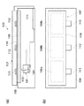
図1は、本発明の実施の形態に係る画像読取装置の概略構成を示す図であり、図1(a)は側面図であり、図1(b)は平面図である。 FIG. 1 is a diagram showing a schematic configuration of an image reading apparatus according to an embodiment of the present invention. FIG. 1 (a) is a side view and FIG. 1 (b) is a plan view.
図1において、画像読取装置100は、3つのコマから成る透過原稿としての読取原稿105を載置するコンタクトガラス106と、コンタクトガラス106の上に載置された読取原稿105を照明すべく当該読取原稿105の上に配される透過原稿用照明装置107と、透過原稿用照明装置107に接続された後述する図2の電気基板109と、電気基板109に接続されると共に、コンタクトガラス106の下方で副走査(矢印)方向に移動するコンタクトイメージセンサ(CIS)101(画像読取手段)とを備える。コンタクトガラス106上の画像読み取り領域は3つの透過原稿領域108a,108b,108cとして制御される。
In FIG. 1, the
透過原稿用照明装置107は、原稿側の面に光拡散シート(不図示)が設置された面状導光体110と、1箇所あたりR,G,B各色の透過原稿用発光ダイオード(LED)を備え、3つの透過原稿領域108a,108b,108cに夫々対応して面状導光体110の側部3箇所に配されたLEDユニット111,112,113とを備える。LEDユニット111が備えるR,G,B各色の透過原稿用発光ダイオードは、導光体110の構造と不図示の光拡散シートにより、透過原稿領域108aを略均一に照明する。他のLEDユニット112,113も同様に対応する透過原稿領域108b,108cを夫々略均一に照明する。
The
イメージセンサ101は、読取原稿105を透過した透過光をコンタクトガラス106を介して受光するレンズアレイ103と、受光した光を光電変換するモノクロイメージセンサ104とを備え、さらに、反射原稿用LED、線状導光体、を搭載している不図示の反射原稿用照明装置を備える。
The
上記画像読取装置100は、透過原稿読取時に以下のように作動する。
The
透過原稿読取時には透過原稿用LEDユニット111,112,113からの照射光を面状導光体110を介して読取原稿105に照射する。このとき、画像読取装置100は、コンタクトイメージセンサ101を原稿に沿って副走査(矢印)方向に移動させながら、1ライン毎に先ずLEDユニット111のR,G,B各色を切り替えて点灯させることにより、読取原稿105からのR,G,B各色の透過光をモノクロイメージセンサ104で受光すると共に、受光量に相応する電気的な画像信号に光電変換する。この各画像信号に対し、電気基板109において画像処理を施して2次元カラー透過原稿画像を得る。
At the time of reading a transparent original, the read original 105 is irradiated with light from the transparent
また、画像読取装置100は、上記の透過原稿読取動作時にコンタクトイメージセンサ101の副走査方向における位置に応じて、透過原稿領域108a,108b,108cに対応して、点灯LEDユニットをLEDユニット111,LEDユニット112,LEDユニット113の順に切り替えて点灯していくことで複数コマの透過原稿画像の読取を行う。
Further, the
モノクロイメージセンサ104にて光電変換された電気信号は、電気的に接続された電気基板109に送られる。
The electric signal photoelectrically converted by the
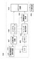
図2は、図1の画像読取装置100における電気基板109を含む各種処理回路のブロック図である。
FIG. 2 is a block diagram of various processing circuits including the
図2において、電気基板109は、図1におけるコンタクトイメージセンサ(CIS)101より出力された電気信号に対してアンプ増幅、DCオフセット補正、A/D変換等の処理を行いデジタル画像データを出力するアナログ・フロントエンド・プリプロセッサであるAFE402と、AFE402から出力されたデジタル画像データのシェーディング補正を行うシェーディング補正回路403と、シェーディング補正回路403での補正後の画像データに対してガンマ変換処理やパッキング処理等の所定の処理を行う画像処理回路404と、画像読取装置100のホスト装置となる外部装置406との間でコントロール信号の受容や画像信号の出力を行うインターフェース回路405とを直列に備える。
In FIG. 2, an
シェーディング補正回路403は、コンタクトイメージセンサ101が透過原稿用照明装置107からの照射光を読み取って作成した基準レベルのデータに基づいてシェーディング補正を行う。この基準レベルのデータは、予め外部装置406に記録されており、透過原稿読取時にシェーディング補正回路403がインターフェース回路405を介して外部装置406から取得する。
The
画像処理回路404は、外部装置406で予め設定された画像読取モード(2値,24ビット多値など)をインターフェース回路405を介して取得し、この取得された画像読取モードに従ってパッキング処理を行う。
The
外部装置406は、画像読取装置100を制御するためのスキャナドライバを有しており、画像読取装置100と一体となって画像処理システムを構成する。このスキャナドライバは、外部装置406のコンピュータで実行されるソフトウエアであり、上述の画像読取モードの指定、解像度指定、読取範囲の指定を行うためのユーザーインターフェースを有し、各指定に基づくコントロール信号や読取開始命令等をインターフェース回路405を介して画像読取装置100に送信する。また、スキャナドライバは、画像読取装置100で読み取った画像データをインターフェース回路405を介して外部装置406に送信する制御や、その送信された画像データを外部装置406の不図示のディスプレイに表示する制御も行う。
The
光源切替回路407は、CIS101内の反射原稿用LEDと透過原稿用照明装置107内の透過原稿用LEDユニット111,112,113を切替駆動する。システムコントローラ408は、画像読取装置100全体の制御を行う。
The light
図3は、図1における透過原稿用照明装置107の光源切替回路407のブロック図である。
FIG. 3 is a block diagram of the light
図3において、光源点灯制御回路508は、R,G,Bの夫々の色のLEDの点灯を制御する。R−LED駆動回路501は、光源点灯制御回路508により赤色LEDの点灯が指示された期間、R−LEDを駆動する。G−LED、B−LEDも同様に夫々緑色、青色のLEDを駆動する。透過原稿を読み取るときには、透過原稿読み取り用に設定された駆動電流で各LEDを駆動し、反射原稿を読み取るときには、反射原稿読み取り用に設定された駆動電流で各LEDを駆動する。さらに、透過原稿読み取りでは、透過原稿がネガかポジかに応じて駆動電流を変える。SW502は、光源切替制御回路510からの指示により、LED駆動回路501の駆動電流を、透過原稿用LEDユニット111、112、113の何れかに接続するか、あるいは反射原稿用LED114に接続するかを切替える。SW503は、点灯位置切替制御回路509からの指示により、SW502を3組の透過原稿用LEDユニット111、112、113の何れの組に接続するかを切替える。例えば、SW502が透過原稿用LEDに接続され、SW503が透過原稿用LEDユニット111に接続されていると、LED駆動回路501は透過原稿用LEDユニット111の3色のLEDを駆動するように接続される。また、光源点灯制御回路508は、カラー画像読取の主走査方向1ラインを読み取る間に、R、G、BのLEDが順番に点灯するように制御する。画像読取装置100は、夫々の色のLEDが点灯している期間に各々の色の主走査方向1ラインの信号を読み取る。読み取った信号は外部装置406に送る。外部装置406はこの信号を受け取って3色のカラー画像信号を得る。
In FIG. 3, a light source
図4は、図1の画像読取装置100によって実行される透過原稿読取処理のフローチャートである。透過原稿読取か反射原稿読取か、また、透過原稿がネガかポジかは、ユーザからの設定で切り替えることができ、また、原稿を自動検知することで設定することもできる。ここでは、透過原稿が設定されており、光源切替制御回路510は透過原稿用LEDを指示しており、SW502によってLED駆動回路501の出力はSW503に接続されている。
FIG. 4 is a flowchart of the transparent original reading process executed by the
図4において、まず、画像読取装置100は、電源投入後にイニシャライズが完了すると、外部装置406に格納されているスキャナドライバから透過原稿である読取原稿105の読取開始命令をインターフェース回路405を介して受信するのを待ち、この受信がされたときに(ステップS600でYES)、点灯位置切替制御回路509が点灯位置切替制御用SW503にて、まず、LED駆動回路501を透過原稿用LEDユニット111と接続する(ステップS601)。
In FIG. 4, first, when initialization is completed after the power is turned on, the
次に、画像読取装置100は、インターフェース回路405を介してスキャナドライバからプリスキャン開始命令を受信すると(ステップS602でYES)、プリスキャン処理を行う(ステップS603)。この処理は、具体的には、まず、点灯位置切替制御回路509がLED駆動回路501を駆動し、透過原稿用LEDユニット111のR−LEDを点灯して透過原稿にR−LED光を1ライン分照射し、読取原稿105からの透過光をモノクロイメージセンサ104にR読取信号として蓄積する。次に、透過原稿用LEDユニット111のG−LEDを点灯して、R−LEDと同様の処理を行う。この間、前にモノクロイメージセンサ104に蓄積されたR−LED色の主走査方向1ライン分のR読取信号がモノクロイメージセンサ104から図2のAFE402に出力信号として出力される。
Next, when receiving a pre-scan start command from the scanner driver via the interface circuit 405 (YES in step S602), the
以下同様に、透過原稿用LEDユニット111のB−LEDの点灯中にG読取信号がAFE402に出力される。その後、コンタクトイメージセンサ101が原稿に沿って副走査方向に1ライン分移動した後、次の1ラインの透過原稿の画像を読み取るために透過原稿用LEDユニット111のR−LEDが点灯している間に、透過原稿用LEDユニット111のB読取信号が出力される。このようにして、R,G,Bの各色の読取信号が1ラインずつモノクロイメージセンサ104からAFE402に出力信号として出力される。
Similarly, the G reading signal is output to the
このプリスキャン処理は、インターフェース回路405を介してスキャナドライバから取得した読取原稿105の一つの透過原稿領域108a,108b,又は108cにおける指定ラインまで行われると(ステップS604でYES)、透過原稿用LEDユニット111,112,113の全てによるプリスキャン処理が終了したか否かを判別し(ステップS605)、終了していないときは、点灯位置切替制御回路509がLED点灯位置を切り替えて(ステップS606)、ステップS603以降の処理を繰り返す。具体的には、上述したように、透過原稿用LEDユニット111についてのプリスキャン処理のみが終了している場合は、透過原稿用LEDユニット112についてのプリスキャン処理(ステップS603)を読取原稿105の次の一つの透過原稿領域108bにおける指定ラインが終了するまで(S604でYES)行い、その後、透過原稿用LEDユニット113についてのプリスキャン処理(ステップS603)を読取原稿105の最後の透過原稿領域108cにおける指定ラインが終了するまで(S604でYES)行う。
When this pre-scan processing is performed up to the designated line in one transparent
一方、ステップS605の判別の結果、透過原稿用LEDユニット111,112,113の全てによるプリスキャン処理が終了したときは、そのプリスキャンの結果を外部装置406に送信する。これにより、外部装置406は不図示のモニタでプリスキャンの結果を表示することができ、ユーザはプリスキャンが所望の範囲で行われているかどうか等をチェックすることができる。
On the other hand, as a result of the determination in
次に、画像読取装置100は、インターフェース回路405を介してスキャナドライバから本スキャン開始命令を受信すると(ステップS607でYES)、本スキャン処理を行う(ステップS608)。このスキャン処理は、上述のプリスキャン処理(ステップS603)と略同様の処理であり、通常スキャナドライバから受信する設定は、読取範囲が指定され、読み取り解像度の設定がプリスキャン処理の場合の設定と比べて高い。
Next, when receiving a main scan start command from the scanner driver via the interface circuit 405 (YES in step S607), the
この本スキャン処理についても、モノクロイメージセンサ104が指定ライン分の読み取りを終了すると(ステップS609でYES)、透過原稿用LEDユニット111,112,113の全てによる本スキャン処理が終了したか否かを判別し(ステップS610)、終了していないときは、点灯位置切替制御回路509がLED点灯位置を切り替え(ステップS611)、ステップS608以降の処理を繰り返す。
Also in the main scanning process, when the
一方、ステップS610の判別の結果、透過原稿用LEDユニット111,112,113の全てによる本スキャン処理が終了したときは、その本スキャンの結果を外部装置406に送信して、本処理を終了する。
On the other hand, as a result of the determination in step S610, when the main scan processing by all of the transparent
以上、本実施の形態によれば、透過原稿用LEDユニット111がRGBの3つのLED光を順次切り替えて、読取原稿105の1コマを照射することによりモノクロイメージセンサ104が指定ライン分の読取りを終了した後(ステップS604でYES)、透過原稿用LEDユニット111,112,113の全てによるプリスキャン処理が終了するまで(ステップS605でYES)、点灯位置切替制御回路509がLED点灯位置を切り替えることにより、透過原稿用LEDユニット112,113について同様の処理を行う(ステップS611)ので、モノクロイメージセンサ104による画像の読取位置に応じて透過原稿用LEDユニット111,112,113の点灯を順次切り替えると共に、この切り替えられた点灯光源の1つにおける複数の光源を順次切り替えることができ、透過原稿の読取用光源の消費電力を低減させることができる。
As described above, according to the present embodiment, the
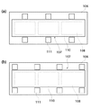
本実施の形態では、透過原稿用LEDユニット111,112,113は、図1(b)に示すように、各透過原稿領域108の片側中央位置に配されているが、図5(a)に示すように、各透過原稿領域108の両側中央位置に配されてもよく、図5(b)に示すように、各透過原稿領域108の両側隅角位置にあってもよい。これにより、より精度よく複数コマから成る読取原稿105の読取を行うことができる。また、図1,5の説明では、3コマの画像を有する透過原稿105に対して、透過原稿領域108を3つ設定して、3箇所の点灯位置を切り替えているが、6コマの画像を有する透過原稿に対して、2コマで一つの透過原稿領域として、全体で3つの透過原稿領域を設定し、6コマに対して、3箇所のLEDの位置を切り替えて照明して読み取る等の変形もできる。また、透過原稿用LEDユニット111,112,113を白色LEDにて構成し、CISでの読み取りをモノクロイメージセンサ104の代わりに3色のカラーフィルタを有するイメージセンサにて読み取ることもできる。
In the present embodiment, the transparent
100 画像読取装置
104 モノクロイメージセンサ
105 読取原稿
107 透過原稿用照明装置
108 透過原稿領域
109 電気基板
110 面状導光体
111,112,113 透過原稿用LEDユニット
DESCRIPTION OF
Claims (8)
前記複数の光源ユニットは、前記複数の透過原稿領域の夫々に対応した位置で、前記移動の方向に並べて配置され、
前記画像読取手段の移動した読取位置に設定されている前記透過原稿領域に応じて前記複数の光源ユニットのうちの点灯する光源ユニットを切り替える光源ユニット切替手段を備えることを特徴とする画像読取装置。 A platen glass having a plurality of transmissive original area while placing a transparent original is set, a plurality of light source units for irradiating light to the placing permeate document moves along the platen glass An image reading apparatus comprising: an image reading unit configured to receive light transmitted to the transparent original by the plurality of light source units and transmitted through the transparent original, and to read an image of the transparent original;
The plurality of light source units are arranged side by side in the movement direction at positions corresponding to the plurality of transparent document regions,
Read image, characterized in that it comprises a light source unit switching unit to switch the lighting to the light source unit of the plurality of light source units in accordance with the transmission document area that has been set to the moved reading position of said image reading means apparatus.
Priority Applications (1)
| Application Number | Priority Date | Filing Date | Title |
|---|---|---|---|
| JP2004028480A JP4471348B2 (en) | 2004-02-04 | 2004-02-04 | Image reading device |
Applications Claiming Priority (1)
| Application Number | Priority Date | Filing Date | Title |
|---|---|---|---|
| JP2004028480A JP4471348B2 (en) | 2004-02-04 | 2004-02-04 | Image reading device |
Publications (3)
| Publication Number | Publication Date |
|---|---|
| JP2005221665A JP2005221665A (en) | 2005-08-18 |
| JP2005221665A5 JP2005221665A5 (en) | 2007-03-22 |
| JP4471348B2 true JP4471348B2 (en) | 2010-06-02 |
Family
ID=34997361
Family Applications (1)
| Application Number | Title | Priority Date | Filing Date |
|---|---|---|---|
| JP2004028480A Expired - Lifetime JP4471348B2 (en) | 2004-02-04 | 2004-02-04 | Image reading device |
Country Status (1)
| Country | Link |
|---|---|
| JP (1) | JP4471348B2 (en) |
-
2004
- 2004-02-04 JP JP2004028480A patent/JP4471348B2/en not_active Expired - Lifetime
Also Published As
| Publication number | Publication date |
|---|---|
| JP2005221665A (en) | 2005-08-18 |
Similar Documents
| Publication | Publication Date | Title |
|---|---|---|
| JP4971598B2 (en) | LIGHTING DEVICE, IMAGE READING DEVICE, AND IMAGE READING METHOD | |
| US8363294B2 (en) | Image processing apparatus and method of controlling the same | |
| US20060023271A1 (en) | Scanner with color profile matching mechanism | |
| JP2007306078A (en) | Image reading apparatus and image reading method | |
| US8610978B2 (en) | Document reading apparatus | |
| US20030202225A1 (en) | Image reading apparatus | |
| JP2004064406A (en) | Image reading device and its control program | |
| JP4471348B2 (en) | Image reading device | |
| JP4498243B2 (en) | Image reading apparatus and power control method | |
| JP2006304200A (en) | Image reading device | |
| JP2002218167A (en) | Image reader | |
| JP2004221729A (en) | Close contact type image sensor and close contact type image reader using the same | |
| JP2007049315A (en) | Image reading apparatus and image reading method | |
| JP2003158612A (en) | Image reader | |
| JP2000287036A (en) | Image reader, its method and computer-readable storage medium | |
| JP2007129286A (en) | Image reading method and image reading apparatus | |
| JP2005203924A (en) | Original-reading apparatus, computer program, original-reading system, and original-reading method | |
| CN1708090A (en) | Surface illumination unit and transparent original reading apparatus | |
| JP3168020B2 (en) | Image reading apparatus and method | |
| JP3172206B2 (en) | Image reading device | |
| JP2008005388A (en) | Image reading apparatus | |
| JP4115339B2 (en) | Image reading device | |
| JP2004172805A (en) | Image-reading device with manuscript transparent reading unit | |
| JPH08317192A (en) | Color image reader | |
| JP2009212754A (en) | Image reader and image reading method |
Legal Events
| Date | Code | Title | Description |
|---|---|---|---|
| RD03 | Notification of appointment of power of attorney |
Free format text: JAPANESE INTERMEDIATE CODE: A7423 Effective date: 20060418 |
|
| A521 | Written amendment |
Free format text: JAPANESE INTERMEDIATE CODE: A523 Effective date: 20070205 |
|
| A621 | Written request for application examination |
Free format text: JAPANESE INTERMEDIATE CODE: A621 Effective date: 20070205 |
|
| RD05 | Notification of revocation of power of attorney |
Free format text: JAPANESE INTERMEDIATE CODE: A7425 Effective date: 20070626 |
|
| A977 | Report on retrieval |
Free format text: JAPANESE INTERMEDIATE CODE: A971007 Effective date: 20091120 |
|
| A131 | Notification of reasons for refusal |
Free format text: JAPANESE INTERMEDIATE CODE: A131 Effective date: 20091201 |
|
| A521 | Written amendment |
Free format text: JAPANESE INTERMEDIATE CODE: A523 Effective date: 20100129 |
|
| TRDD | Decision of grant or rejection written | ||
| A01 | Written decision to grant a patent or to grant a registration (utility model) |
Free format text: JAPANESE INTERMEDIATE CODE: A01 Effective date: 20100226 |
|
| A01 | Written decision to grant a patent or to grant a registration (utility model) |
Free format text: JAPANESE INTERMEDIATE CODE: A01 |
|
| A61 | First payment of annual fees (during grant procedure) |
Free format text: JAPANESE INTERMEDIATE CODE: A61 Effective date: 20100301 |
|
| FPAY | Renewal fee payment (event date is renewal date of database) |
Free format text: PAYMENT UNTIL: 20130312 Year of fee payment: 3 |
|
| R150 | Certificate of patent or registration of utility model |
Free format text: JAPANESE INTERMEDIATE CODE: R150 |