JP4471263B2 - Gear hob cutter system - Google Patents
Gear hob cutter system Download PDFInfo
- Publication number
- JP4471263B2 JP4471263B2 JP2003585943A JP2003585943A JP4471263B2 JP 4471263 B2 JP4471263 B2 JP 4471263B2 JP 2003585943 A JP2003585943 A JP 2003585943A JP 2003585943 A JP2003585943 A JP 2003585943A JP 4471263 B2 JP4471263 B2 JP 4471263B2
- Authority
- JP
- Japan
- Prior art keywords
- cartridge
- receiving groove
- clamp
- cutter head
- cartridge assembly
- Prior art date
- Legal status (The legal status is an assumption and is not a legal conclusion. Google has not performed a legal analysis and makes no representation as to the accuracy of the status listed.)
- Expired - Fee Related
Links
Images


Classifications
-
- B—PERFORMING OPERATIONS; TRANSPORTING
- B23—MACHINE TOOLS; METAL-WORKING NOT OTHERWISE PROVIDED FOR
- B23F—MAKING GEARS OR TOOTHED RACKS
- B23F21/00—Tools specially adapted for use in machines for manufacturing gear teeth
- B23F21/12—Milling tools
- B23F21/22—Face-mills for longitudinally-curved gear teeth
- B23F21/223—Face-mills for longitudinally-curved gear teeth with inserted cutting elements
- B23F21/226—Face-mills for longitudinally-curved gear teeth with inserted cutting elements in exchangeable arrangement
-
- B—PERFORMING OPERATIONS; TRANSPORTING
- B23—MACHINE TOOLS; METAL-WORKING NOT OTHERWISE PROVIDED FOR
- B23C—MILLING
- B23C5/00—Milling-cutters
- B23C5/16—Milling-cutters characterised by physical features other than shape
- B23C5/20—Milling-cutters characterised by physical features other than shape with removable cutter bits or teeth or cutting inserts
- B23C5/202—Plate-like cutting inserts with special form
-
- B—PERFORMING OPERATIONS; TRANSPORTING
- B23—MACHINE TOOLS; METAL-WORKING NOT OTHERWISE PROVIDED FOR
- B23C—MILLING
- B23C5/00—Milling-cutters
- B23C5/16—Milling-cutters characterised by physical features other than shape
- B23C5/20—Milling-cutters characterised by physical features other than shape with removable cutter bits or teeth or cutting inserts
- B23C5/22—Securing arrangements for bits or teeth or cutting inserts
- B23C5/2204—Securing arrangements for bits or teeth or cutting inserts with cutting inserts clamped against the walls of the recess in the cutter body by a clamping member acting upon the wall of a hole in the insert
- B23C5/2226—Securing arrangements for bits or teeth or cutting inserts with cutting inserts clamped against the walls of the recess in the cutter body by a clamping member acting upon the wall of a hole in the insert for plate-like cutting inserts fitted on an intermediate carrier, e.g. shank fixed in the cutter body
-
- B—PERFORMING OPERATIONS; TRANSPORTING
- B23—MACHINE TOOLS; METAL-WORKING NOT OTHERWISE PROVIDED FOR
- B23C—MILLING
- B23C2200/00—Details of milling cutting inserts
- B23C2200/20—Top or side views of the cutting edge
- B23C2200/201—Details of the nose radius and immediately surrounding areas
Landscapes
- Engineering & Computer Science (AREA)
- Mechanical Engineering (AREA)
- Milling Processes (AREA)
- Control Of Cutting Processes (AREA)
- Gear Processing (AREA)
Description
優先権の主張
本願は、2002年4月18日に出願された「歯車ホブ・カッター・システム(Gear Hobbing Cutter System)」という発明の名称である米国特許出願番号第10/125,146号(この内容全体は、参照により本明細書中に組み込まれる)の一部継続出願である。
This application claims US patent application Ser. No. 10 / 125,146 (named “Gear Hobbing Cutter System” filed on April 18, 2002). The entire content is a continuation-in-part application, which is incorporated herein by reference.
本発明は、歯付きの物品を作製するための切削工具に関し、詳細には、正面ホブ切り法(face hobbing methods)により歯車を作製するための歯車ホブ・カッター・システム(gear hobbing cutter system)に関する。 The present invention relates to a cutting tool for making a toothed article, and in particular to a gear hobing cutter system for making a gear by face hobbing methods. .
例えば曲線状の逃げ面(curved flank lines)を備えるかさ歯車及びハイポイド歯車の製造において、利用される切削工具は主に正面フライス・カッター(face mill cutters)又は正面ホブ・カッター(face hob cutters)であり、このようなタイプの切削工具は歯車製造の分野ではよく知られている。正面フライス・カッターでは、カッターの各プランジ(押込み:plunge)によって1つの歯溝が形成されるように、切削刃がカッター・ヘッドに配列されており、次の歯溝を形成するには、カッターを引っ込めて、被削物を次の歯溝位置に割出ししなければならない。 For example, in the production of bevel gears and hypoid gears with curved flank lines, the cutting tools used are mainly face mill cutters or face hob cutters. There are such types of cutting tools well known in the field of gear manufacturing. In the face milling cutter, the cutting blades are arranged in the cutter head so that one tooth groove is formed by each plunge (plunge) of the cutter. The work piece must be indexed to the next tooth gap position.
正面ホブ・カッターは、カッター周囲に切削刃を備えるが、互いに一列になるように配列されるのではなく、グループ毎に配列され、通常、1グループ当たり2つ又は3つの切削刃を備える。2つの刃のグループでは、この刃の組は、内側切削刃と外側切削刃とから構成される。3つの刃のグループでは、内側切削刃及び外側切削刃に加えて「底部」切削刃が含まれる。 Front hob cutters have cutting blades around the cutter, but are not arranged in a row with each other, but are arranged in groups, typically with two or three cutting blades per group. In the group of two blades, the blade set consists of an inner cutting blade and an outer cutting blade. The group of three blades includes a “bottom” cutting blade in addition to the inner and outer cutting blades.
形成中に全ての切削刃が歯溝を通過する大抵の正面フライス加工とは異なり、正面ホブ切り加工では、切削刃の各連続するグループがそれらに対応する連続歯溝を通過して、グループの各刃が歯溝の長手方向部分全体に沿って1つの切り込みを形成する。カッターと被削物とは互いにタイミングの合った関係(timed relationship)で回転しており、これにより、被削物を連続的に割出しして、歯車の各歯溝を連続的に形成することができる。例えば、歯車の歯を生成するホブ切り加工では、適切な生成動作が、工具と被削物とのタイミングの合った関係における回転と重ね合わされる。従って、正面ホブ切り加工では、切削工具の1回のプランジによって、被削物の全ての歯溝が形成される。 Unlike most face milling, where all cutting blades pass through the tooth spaces during formation, in face hobbing, each successive group of cutting blades passes through their corresponding continuous tooth spaces and Each blade forms an incision along the entire longitudinal portion of the tooth space. The cutter and work piece rotate in a timed relationship with each other, so that the work piece is indexed continuously and each tooth gap of the gear is formed continuously. Can do. For example, in hobbing that generates gear teeth, an appropriate generation operation is superimposed on rotation in a timed relationship between the tool and the workpiece. Therefore, in front hobbing, all tooth spaces of the work are formed by a single plunge of the cutting tool.
正面ホブ切り加工用の切削工具は、通常、円盤状のカッター・ヘッドを備え、このカッター・ヘッドに形成された溝には、例えば棒材の高速度鋼(HSS)でできたスティックタイプの切削刃が挿入されて配置されている。各切削刃は、横すくい角として知られる所定の角度で方向付けされたすくい面部分(face portion)、切削端、所定の逃げ角で方向付けされた切削側面、クリアランス端、所定の逃げ角で方向付けされたクリアランス側面、及び頂面を備える。 The cutting tool for front hobbing is usually provided with a disk-shaped cutter head, and the groove formed in the cutter head is, for example, a stick type cutting made of high-speed steel (HSS) of a bar A blade is inserted and arranged. Each cutting edge has a rake face portion oriented at a predetermined angle known as a side rake angle, a cutting edge, a cutting side face oriented at a predetermined clearance angle, a clearance edge, and a predetermined clearance angle. It has a directed clearance side and a top surface.
特定種類の各刃、特に内側刃又は外側刃を、チップ厚さが同じになるようにして、負荷及び摩耗が同じになるようにするには、切削端の半径方向位置が最も重要である。カッター・ヘッドにおける溝の「摩耗」の公差と同様に、刃のシャンク及びこのシャンクに対する切削端の位置の公差は、結局は許容できない公差になり得る。 The radial position of the cutting edge is the most important for each type of blade, especially the inner or outer blade, to have the same tip thickness and the same load and wear. Similar to the groove "wear" tolerance in the cutter head, the tolerance of the blade shank and the position of the cutting edge relative to this shank can eventually be an unacceptable tolerance.
一方、切削刃の半径方向位置は、正面フライス作業でも正面ホブ切り作業でも重要であるが、正面ホブ切り加工では、切削刃の正面の位置(割出し位置)も重要である。このことは、回転している工具と回転している被削物とのタイミングの合った関係を考えれば、理解することができる。切削刃がカッター・ヘッドにおけるその他の同種の刃に対して適切な位置(割出し位置)にない場合、切削刃は、それに対応する歯溝に早く或いは遅く到達することとなる。このような場合、この歯溝から切除されるチップは、他の歯溝において他の切削刃により切除されるチップよりも厚く或いは薄くなり、切削工具における負荷及び摩耗が不均等となる。 On the other hand, the radial position of the cutting blade is important in both front milling and front hobbing operations, but the front position (indexing position) of the cutting blade is also important in front hobbing. This can be understood by considering the timely relationship between the rotating tool and the rotating workpiece. If the cutting blade is not in the proper position (indexing position) relative to other similar blades in the cutter head, the cutting blade will reach the corresponding tooth space early or late. In such a case, the tip cut from the tooth gap becomes thicker or thinner than the tip cut by the other cutting blade in the other tooth gap, and the load and wear on the cutting tool become uneven.
本発明の発明者は、これらの及びその他の課題を認識し、改良された歯車ホブ・カッター・システムを開発した。 The inventors of the present invention have recognized these and other problems and have developed an improved gear hob cutter system.
本発明の特徴は、改良された歯車ホブ・カッター・システムを提供することである。本発明の一態様では、この歯車ホブ・カッター・システムは、カートリッジ及び刃がカッター・ヘッド本体に確実に適切に配置されるようにするエラー防止システムを含み得る。本発明の別の態様では、この歯車ホブ・カッター・システムは、少なくとも2つの切削端を提供し得る割出し可能なインサートから成る複数の刃を含むことにより、よりコスト効率の良い切削システムを提供することができる。 A feature of the present invention is to provide an improved gear hob cutter system. In one aspect of the invention, the gear hob cutter system may include an error prevention system that ensures that the cartridge and blade are properly positioned on the cutter head body. In another aspect of the invention, the gear hob cutter system provides a more cost effective cutting system by including multiple blades of indexable inserts that can provide at least two cutting edges. can do.
本発明は、周辺部の周囲に複数の穴が形成された円盤状のカッター・ヘッド本体を備える、カッター・システムから成る。これらの穴は、クランプ部材を受容するように設計されている。少なくとも1組のカートリッジ受容溝が、外側カートリッジ・アセンブリを受容することのできる外側カートリッジ受容溝と、内側カートリッジ・アセンブリを受容することのできる内側カートリッジ受容溝とを含んで、カッター・ヘッド本体に形成されている。複数のクランプ溝がカッター・ヘッド本体に形成されており、各クランプ溝は、カッター・ヘッド本体の周辺部とそのクランプ溝に対応するカートリッジ受容溝との間に配置されて、このカートリッジ受容溝との間にカッター・ヘッド本体の変形可能領域を形成する。外側カートリッジ受容溝が、内側カートリッジ受容溝とは異なる寸法を有することによって、外側カートリッジ・アセンブリ及び内側カートリッジ・アセンブリがそれらに対応するカートリッジ受容溝内に確実に適切に配置されるようにする、エラー防止システムが形成される。 The present invention comprises a cutter system comprising a disc-shaped cutter head body having a plurality of holes formed around the periphery. These holes are designed to receive clamping members. At least one set of cartridge receiving grooves is formed in the cutter head body, including an outer cartridge receiving groove capable of receiving the outer cartridge assembly and an inner cartridge receiving groove capable of receiving the inner cartridge assembly. Has been. A plurality of clamp grooves are formed in the cutter head main body, and each clamp groove is disposed between a peripheral portion of the cutter head main body and a cartridge receiving groove corresponding to the clamp groove. The deformable region of the cutter head body is formed between the two. An error that ensures that the outer cartridge assembly and the inner cartridge assembly are properly positioned within their corresponding cartridge receiving grooves by having an outer cartridge receiving groove having a different dimension than the inner cartridge receiving groove. A prevention system is formed.
本発明のさらなる特徴及び本発明から得られる利点は、図面と関連させた以下の詳細な説明から明らかとなるであろう。 Further features of the present invention and advantages obtained from the present invention will become apparent from the following detailed description taken in conjunction with the drawings.
図面(ここで、同じ参照符号は同じ要素を表す)を参照すると、正面ホブ切り法により歯車を作製するための歯車ホブ・カッター・システム40が示されている。この歯車ホブ・カッター・システム40は、円盤状のカッター・ヘッド本体42及び複数のカートリッジ・アセンブリ10を含み、これらのカートリッジ・アセンブリ10は、クランプ部材46によってカートリッジ受容溝50内に保持される切削用インサート12を含む。
Referring to the drawings, wherein like reference numerals represent like elements, there is shown a gear hob cutter system 40 for making gears by a face hobbing method. The gear hob cutter system 40 includes a disc-shaped
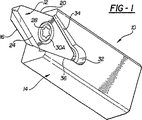
図1〜図4は、参照番号10で概括的にカートリッジ・アセンブリを示しており、このカートリッジ・アセンブリは、本発明の教示により、歯車ホブ・カッター・システムのようなカッター・システムにおいて、形成されて用いられ得る。この図示されているカートリッジ・アセンブリは、図示されているように、例えば4340鋼のような比較的薄いストック材料(stock material)から構成してもよく、より厚い材料を用いてもよい。本発明の一態様では、カートリッジ・アセンブリ10は、単体切削刃を含む従来のカッター・アセンブリとは異なり、切削用インサート12と、このインサート12を取り付けることのできる支持ブロック16を有するカートリッジ14とを含む。支持ブロック16は、カートリッジ14と一体化して形成するのが好ましいが、カートリッジ14とは別に形成して、ねじ山付きファスナーなどのような従来の締結手段を用いることによってカートリッジ14に固定してもよいと考えられる。
1-4 generally illustrate a cartridge assembly at
図1〜図4に最も良く見られるように、支持ブロック16の前面即ち前方表面17は、切削用インサート12を受容する取り付けポケットを形成している。切削用インサート12の後面は、支持ブロック16のこの前面17と嵌合するように、ほぼ相補的に形成されているのが好ましい。切削用インサート12は、支持ブロック16のこの取り付けポケットに取り付けられた又は嵌合された後、アレン(Allen)又はトルクス(Torx)ねじのようなロッキング・ファスナー28(図1に図示)によって支持ブロックにしっかりと固定される。このロッキング・ファスナー28は、切削用インサート12に設けられたクリアランス穴30を通って、支持ブロック16のねじ穴(図示せず)に螺合する。クリアランス穴30はテーパ座ぐり30Aを含み、このテーパ座ぐり30Aがロッキング・ファスナー28の頭部における対応するテーパ面と係合することによって、位置付けファスナー28がテーパ座ぐり30Aを下方に押圧すると、切削用インサート12が支持ブロック16にしっかりと固定される。支持ブロック16の2つのテーパ壁34及び36の交差部に逃げ(relief)32を設けることにより、位置付け面(locating surface)をもたらして、切削用インサート12がカートリッジ14と結合するのを防止してもよい。図2に最も良く見られるように、切削用インサート12は、例えば約5°のポジティブ・アキシャル・レーキ(positive axial rake angle)を有するが、このアキシャル・レーキθ1は、約0°〜約30°の範囲であってよい。
As best seen in FIGS. 1-4, the front or
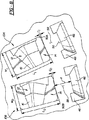
図5〜図9は、図1〜図3に示されたタイプのカートリッジ・アセンブリ10を保持するように設計されたカッター・システム40の一部を示している。このカッター・システム40は、歯車ホブ・カッター形態で示されているが、あらゆるタイプの正面フライス又はホブ切り作業において用いられてもよい。この歯車ホブ・カッター・システム40は、円盤状のカッター・ヘッド本体42を含む。このカッター・ヘッド本体42は、歯車切削装置(図示せず)のスピンドルに取り付けられる手段を含むように、既知の方式で形成され得る。
FIGS. 5-9 show a portion of a cutter system 40 designed to hold a
カッター・ヘッド本体42は、その周辺部に、ボルトやねじ山付きねじなどのようなクランプ部材46を受容するために形成された、複数のねじ穴44を含む。図に見られるように、各穴44は、ほぼ同じ形状をしており、カッター・ヘッド本体42の周辺部周囲において、隣接した穴とほぼ等間隔で離間している。これらの穴44は、以下にさらに説明するクランプ溝48と半径方向に位置合わせされ、且つこれらのクランプ溝48と通じている。
The
図6に最も良く示されているように、カッター・ヘッド本体42はさらに、複数のクランプ溝48と、カッター・ヘッド本体41の中心軸Aに対して所定角度で組にして配列された複数のカートリッジ受容溝50とを含む。当然のことながら、好適な実施形態では1グループに一対の刃が示されているが、本発明が開示及び説明されれば、本発明は1グループに一対よりも多くの刃がある形態にも適用可能であることが、当業者には容易に認められるであろう。例えば、カッター・ヘッド本体41は、少なくとも1組のカートリッジ受容溝50を含み、これらのカートリッジ受容溝50は、それぞれ内側カートリッジ・アセンブリ10A及び外側カートリッジ・アセンブリ10Bを受容して収容するように設計された、内側カートリッジ受容溝50A及び外側カートリッジ受容溝50Bから構成される、この構造では、内側カートリッジ・アセンブリ10A及び外側カートリッジ・アセンブリ10Bにおける切削用インサートは、カッター・ヘッド本体42の周囲に一対を一組にして配列することができれば、異なる切削機能を有していてもよい。さらに、内側カートリッジ・アセンブリ10A及び外側カートリッジ・アセンブリ10Bにおける切削用インサートは、これらの異なる切削機能を収容するように異なる寸法であってもよい。
As best shown in FIG. 6, the
各クランプ溝48は、半径方向外側にクランプ部材46に向けて突出するクランプ・パッド56を含む。このクランプ・パッド56は、クランプ部材46が締め付けられてクランプ・パッド56を押圧すると、クランプ部材46によって及ぼされる付勢力を分散させるように設計されている。図示されている実施形態では、各クランプ・パッド56の断面は、ほぼ長方形であるが、クランプ部材46によって及ぼされる付勢力を最適に分散させるような、あらゆる所望の形状であってもよい。図8〜図11に最も良く示されているように、カートリッジ受容溝50とクランプ溝48との間には、カッター・ヘッド本体42の変形可能領域58が形成されている。具体的には、この変形可能領域58は、クランプ・パッド56とクランプ受容溝50A及び50Bとの間において、適切な距離dを有する。この適切な距離dによって、変形可能領域58は、クランプ部材46がクランプ・パッド56に対して十分な量の付勢力を及ぼすと、カートリッジ・アセンブリ10A及び10Bを押圧する。当然のことながら、この適切な距離dは、カッター・ヘッド本体42の材料特性に応じて決められる。例えば、本発明の図示されている実施形態では、カッター・ヘッド本体がばね鋼でできている場合、この距離dは、約0.200〜約0.400インチの間の範囲、好ましくは約0.260インチであり得る。
Each
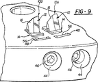
内側カートリッジ・アセンブリ52及び外側カートリッジ・アセンブリ54を形成しているカートリッジ・アセンブリ10はそれぞれ、それらに対応するカートリッジ受容溝50A及び50B内に受容される。本発明の一態様は、これらの内側カートリッジ・アセンブリ10A及び外側カートリッジ・アセンブリ10Bが、それらに対応するカートリッジ受容溝50A及び50B内に確実に適切に配置されるようにする、エラー防止システムである。このエラー防止システムは、内側カートリッジ受容溝50Aを外側カートリッジ受容溝50Bとは長さ又は幅のような寸法が異なるように構成することによって、或いはこの逆によって実現される。つまり、内側カートリッジ受容溝50A及びこれに対応する内側カートリッジ・アセンブリ10Aの長さLI又は幅WIが、外側カートリッジ受容溝50B及びこれに対応する外側カートリッジ・アセンブリ10Bの長さLO又は幅WOと異なる。この寸法の違いによって、内側カートリッジ・アセンブリ10Aを外側カートリッジ受容溝50Bに不用意に入れることはできない。同様に、外側カートリッジ・アセンブリ10Bを内側カートリッジ受容溝50Aに不用意に入れることはできない。従って、作業者は確実に、内側カートリッジ・アセンブリ10A及び外側カートリッジ・アセンブリ10Bが、それらに対応するカートリッジ受容溝50A及び50B内に適切に配置されるようにすることができる。
The
さらに、カートリッジ受容溝50A及び50Bの長さ及び幅と、これらに対応するカートリッジ・アセンブリ10A及び10Bの長さ及び幅とを、わずかに、例えばおよそ0.005インチ異ならせることによって、カートリッジ・アセンブリ10A及び10Bがカートリッジ受容溝50A及び50B内に適切に配置されたとき、カートリッジ・アセンブリ10A及び10Bとこれらに対応するカートリッジ受容溝50A及び50Bとの間にクリアランスCI及びCOができるようにする。より具体的には、カートリッジ・アセンブリ10A及び10Bのカートリッジ14の長さLI及びLOと、それらに対応するカートリッジ受容溝50A及び50Bの長さLI及びLOとは、わずかに異なる。クリアランスCI及びCOによって、内側カートリッジ・アセンブリ10A及び外側カートリッジ・アセンブリ10Bを、それらに対応するカートリッジ受容溝50A及び50Bに適切に配置することができる。しかしながら、それぞれのクランプ部材46が特定のクランプ力でクランプ・パッド56を押圧すると、変形可能領域58が内側カートリッジ・アセンブリ10A及び外側カートリッジ・アセンブリ10Bを押圧し、これにより、関連するカートリッジ・アセンブリ10A及び10Bをカートリッジ受容溝50A及び50B内に確実に固定する。
Further, by varying the length and width of the
クランプ部材46がクランプ・パッド56を押圧しないようにして、カッター・ヘッド本体42の変形可能領域58を形成している部分の弾性により、カートリッジ・アセンブリ10A及び10Bとそれらに対応するカートリッジ受容溝50A及び50Bとの間にクリアランスができるようにすることによって、内側カートリッジ・アセンブリ10A及び外側カートリッジ・アセンブリ10Bをそれらに対応するカートリッジ受容溝50A及び50Bから取り外すことができる、ということに注意されたい。また、カートリッジ・アセンブリ10A及び10Bがカートリッジ受容溝50A及び50B内に適切に配置されたとき、カートリッジ・アセンブリ10A及び10Bとそれらに対応するカートリッジ受容溝50A及び50Bとの間のクリアランスCI及びCOは異なり得る、ということにも注意されたい。
Due to the elasticity of the portion of the
次に、図12〜図15を参照すると、切削用インサート12は、ほぼ菱形をしており、前面即ち頂面18、第1組の対向する側壁即ち側面21及び25、第2組の対向する側壁即ち側面23及び27、並びに、支持ブロック14の前面17と嵌合する底面即ち後面19を含む。図示されている実施形態では、頂面18及び後面19は、ほぼ平面形状をしている。しかしながら、その他の形状も考えられ、本発明はあらゆる所望の形状をした頂面及び底面を用いて実施することができる。頂面18と側壁21、23、25、及び27との交差部には、主に4つの端部、即ち、1組の対向し且つ離間した端部20及び22と、もう1組の対向し且つ離間した端部24及び26とが形成されている。これらの端部20、22、24、及び26のうちの少なくとも1つ、好ましくは少なくとも2つの対向する端部が切削端であり、これにより、切削用インサート12を割出し可能とすることができる。
Referring now to FIGS. 12-15, the cutting
例えば、本発明の一実施形態は、切削用インサート12をおよそ180°回転させることにより2つの切削端において割出し可能な、切削用インサート12を提供する。端部20と端部24とは互いに、例えばおよそ30°の角度θを形成するのが好ましい。当然のことながら、本発明は、この角度の切削端に限定されず、あらゆる所望の角度の切削端を用いて実施することができる。例えば、角度θが0°〜60°の切削端を含む、その他の形状をしたインサートが考えられる。
For example, one embodiment of the present invention provides a cutting
さらに、切削用インサート12は、1組の対向する端壁29及び31を含み、これらの端壁29及び31は、頂面18から底面19へテーパ加工されていてもよい。つまり、頂面18の方が底面19よりも、表面積がわずかに大きくてもよい。本発明の切削用インサート12は、摩耗した場合、従来の切削アセンブリのように切削刃全体を廃棄するのではなく、切削用インサート12のみを交換すればよいので、実質的にコストを削減することができる。
In addition, the cutting
次に、図16及び図17を参照すると、本発明の別の実施形態による、カッター・ヘッド本体42’を備えた切削システム10’が示されている。このカッター・ヘッド本体42’は、カッター・ヘッド本体42’の変形可能領域58’が、所定のパターンを有する1つ以上の溝60により画定され且つカートリッジ受容溝50A及び50Bに隣接した屈曲領域58a’を含むこと以外は、カッター・ヘッド本体42と同一である。カッター・ヘッド本体42と比較すると、この屈曲領域58a’は、クランプ部材46がクランプ・パッド56を押圧するときに及ぼすより小さな力で、変形可能領域58’がカートリッジ・アセンブリ10A及び10Bとより確実に係合できるように設計されている。
16 and 17, there is shown a cutting system 10 'with a cutter head body 42' according to another embodiment of the present invention. The cutter head body 42 'includes a bend area 58a in which the deformable area 58' of the cutter head body 42 'is defined by one or
具体的には、溝60は、屈曲領域58a’に近接して、カートリッジ受容溝50A及び50Bに対しほぼ垂直に外側に延びる、1組の溝60aにより画定される。さらに、これらの溝60は、各クランプ溝48の外側端部48aから互いにほぼ平行に外側に延びる、もう1組の溝60bにより画定される。さらに、これらの溝60は、溝60bの端部から互いに向かって延びる、1組の溝60cにより画定される。従って、溝60aと溝60cとは、互いにほぼ平行である。
Specifically, the
図示されている実施形態では、これらの溝60a、60b、及び60cは、製造公差に基づいて、およそ0.017インチの太さtを有する。しかしながら、これらの溝60a、60b、及び/又は60cは、屈曲領域58a’を形成する所望の所定パターンの溝に応じて異なる太さを有していてもよいと考えられる。 In the illustrated embodiment, these grooves 60a, 60b, and 60c have a thickness t of approximately 0.017 inches based on manufacturing tolerances. However, it is contemplated that these grooves 60a, 60b and / or 60c may have different thicknesses depending on the desired predetermined pattern of grooves forming the bend region 58a '.
上述したように、屈曲領域58a’とは、カッター・ヘッド本体42’の、溝60aと溝60cとの間の距離d×溝60aの最も外側の端部間の距離で得られる領域として定義される。この距離dによって、カートリッジ・アセンブリ50A及び50Bを確実に固定するのに、クランプ部材46によってクランプ・パッド56に及ぼされる必要のある力の量が決まる。つまり、この距離dによって、力がクランプ部材46によってクランプ・パッド56に及ぼされたときの、変形可能領域58’の屈曲量が決まる。従って、この距離dを選択することによって、クランプ部材46によってクランプ・パッド56に及ぼされる必要のある力の量を決定することができる。図示されている実施形態では、溝60aと溝60cとの間の距離dは、およそ0.023インチである。一方、カッター・ヘッド本体42’に用いられる材料も、クランプ部材46によってクランプ・パッド56に及ぼされる特定量の力に関わる、溝60aと溝60cとの間の距離dの量に影響を与え得る。
As described above, the bent region 58a ′ is defined as a region obtained by the distance d between the groove 60a and the groove 60c of the
上記のように、溝60cは、溝60bから互いに向かって延びている。しかしながら、これらの溝60cは、変形可能領域58’全体を横断するようには延びておらず、溝60c間に幅Wをもたらすように終端している。図示されている実施形態では、この幅Wはおよそ0.090インチである。この幅Wは、クランプ部材46によってクランプ・パッド56に及ぼされる必要のある力の量を決定する、溝60aと溝60cとの間の距離dほどには重要でない、ということに注意されたい。従って、この幅Wは、製造公差によってのみ制限されるあらゆる所望の幅であってよい。
As described above, the groove 60c extends from the groove 60b toward each other. However, these grooves 60c do not extend across the entire deformable region 58 'and terminate to provide a width W between the grooves 60c. In the illustrated embodiment, this width W is approximately 0.090 inches. Note that this width W is not as important as the distance d between the grooves 60a and 60c, which determines the amount of force that needs to be exerted on the
上述したように、本発明は、従来のカッター・アセンブリにおけるような切削刃ではなく切削用インサートを含むことにより、実質的にコストを削減することのできる、歯車ホブ・カッター・システムのようなカッター・システムを提供する。さらに、本発明の切削用インサートは、少なくとも2つの切削端で割出し可能であることにより、切削刃を備える従来のカッター・アセンブリに比べて、さらにコストを削減することができる。さらに、本発明は、カートリッジ・アセンブリがそれらに対応するカートリッジ受容溝に確実に適切に配置されるようにする、エラー防止システムを含む。 As mentioned above, the present invention provides a cutter, such as a gear hob cutter system, that can substantially reduce costs by including a cutting insert rather than a cutting blade as in conventional cutter assemblies.・ Provide a system. Furthermore, the cutting insert of the present invention can be indexed with at least two cutting edges, thereby further reducing the cost compared to a conventional cutter assembly having a cutting blade. In addition, the present invention includes an error prevention system that ensures that cartridge assemblies are properly positioned in their corresponding cartridge receiving grooves.
本発明を、ある特定の実施形態に関して具体的に説明してきたが、これは例示であって限定ではなく、添付の特許請求の範囲は、従来技術が許容する範囲で広く解釈されるべきである、ということは理解されたい。 Although the invention has been described in detail with reference to certain specific embodiments, this is illustrative and not restrictive, and the appended claims should be construed broadly to the extent permitted by the prior art. I want you to understand.
Claims (28)
前記カッター・ヘッド本体の周辺部に形成された、クランプ部材を受容することのできる少なくとも1つの穴を備え、
前記カッター・ヘッド本体に形成された、カートリッジ・アセンブリを受容することのできる少なくとも1つのカートリッジ受容溝を備え、
前記カッター・ヘッド本体に形成され、且つ、前記カッター・ヘッド本体の前記周辺部と前記少なくとも1つのカートリッジ受容溝との間に配置された、少なくとも1つのクランプ溝を備え、該クランプ溝が、前記カートリッジ受容溝との間に前記カッター・ヘッド本体の変形可能領域を形成し、該変形可能領域が、該変形可能領域に形成された所定パターンの溝により画定される屈曲領域を含み、
前記屈曲領域によって、前記カートリッジ・アセンブリを前記カッター・ヘッド本体に固定するのに、前記クランプ部材によって前記少なくとも1つのカートリッジ受容溝に及ぼされる必要のある力の量が決まり、
前記少なくとも1つのクランプ溝のそれぞれが、該クランプ溝から突出するクランプ・パッドを含み、前記クランプ部材が前記クランプ・パッドを押圧することによって、前記屈曲領域が前記カートリッジ・アセンブリを押圧して、前記カートリッジ・アセンブリが前記カッター・ヘッド本体に固定される、
カッター・システム。It has a disc-shaped cutter head body,
Comprising at least one hole formed in a peripheral portion of the cutter head body for receiving a clamp member;
Comprising at least one cartridge receiving groove formed in the cutter head body for receiving a cartridge assembly;
At least one clamp groove formed in the cutter head body and disposed between the peripheral portion of the cutter head body and the at least one cartridge receiving groove, the clamp groove comprising: Forming a deformable region of the cutter head body with a cartridge receiving groove, the deformable region including a bent region defined by a predetermined pattern of grooves formed in the deformable region;
Wherein the bending region, for fixing said cartridge assembly to said cutter head body, Ri amount of force that must be exerted on the at least one cartridge-receiving groove by the clamping member KOR,
Each of the at least one clamp groove includes a clamp pad projecting from the clamp groove, and the bending member presses the clamp pad so that the bent region presses the cartridge assembly, and A cartridge assembly is secured to the cutter head body;
Cutter system.
前記カッター・ヘッド本体の周辺部に形成された、クランプ部材を受容することのできる複数の穴を備え、
前記カッター・ヘッド本体に形成され、且つ、外側カートリッジ・アセンブリを受容することのできる外側カートリッジ受容溝と、内側カートリッジ・アセンブリを受容することのできる内側カートリッジ受容溝とを含む、少なくとも1組のカートリッジ受容溝を備え、該内側カートリッジ・アセンブリ及び該外側カートリッジ・アセンブリがそれぞれ、カートリッジと、支持ブロックと、該支持ブロックに取り付けられた割出し可能な切削用インサートとを備え、
前記カッター・ヘッド本体に形成され、且つ、前記カッター・ヘッド本体の前記周辺部と前記少なくとも1つのカートリッジ受容溝との間に配置された、複数のクランプ溝を備え、該クランプ溝が、前記カートリッジ受容溝との間に前記カッター・ヘッド本体の変形可能領域を形成し、該変形可能領域が、該変形可能領域に形成された所定パターンの溝により画定される屈曲領域を含み、
前記クランプ溝のそれぞれが、該クランプ溝から突出するクランプ・パッドを含み、前記クランプ部材が前記クランプ・パッドを押圧することによって、前記屈曲領域が前記カートリッジを押圧して、前記カートリッジ・アセンブリが前記カッター・ヘッド本体に固定される、
カッター・システム。It has a disc-shaped cutter head body,
A plurality of holes formed in the periphery of the cutter head body and capable of receiving a clamp member;
At least one set of cartridges formed in the cutter head body and including an outer cartridge receiving groove capable of receiving an outer cartridge assembly and an inner cartridge receiving groove capable of receiving an inner cartridge assembly A receiving groove, the inner cartridge assembly and the outer cartridge assembly each comprising a cartridge, a support block, and an indexable cutting insert attached to the support block;
A plurality of clamp grooves formed in the cutter head main body and disposed between the peripheral portion of the cutter head main body and the at least one cartridge receiving groove, the clamp groove including the cartridge deformable area of the cutter head body between the receiving groove is formed, deformable region, viewed contains a bending region defined by the groove of the predetermined pattern formed on a deformable region,
Each of the clamp grooves includes a clamp pad protruding from the clamp groove, and when the clamp member presses the clamp pad, the bent region presses the cartridge, and the cartridge assembly includes the cartridge assembly. Fixed to the cutter head body,
Cutter system.
前記カッター・ヘッド本体の周辺部に形成された、クランプ部材を受容することのできる複数の穴を備え、
前記カッター・ヘッド本体に形成され、且つ、外側カートリッジ・アセンブリを受容することのできる外側カートリッジ受容溝と、内側カートリッジ・アセンブリを受容することのできる内側カートリッジ受容溝とを含む、少なくとも1組のカートリッジ受容溝を備え、
前記カッター・ヘッド本体に形成された複数のクランプ溝を備え、該クランプ溝のそれぞれが、前記カッター・ヘッド本体の前記周辺部と該クランプ溝に対応する前記カートリッジ受容溝との間に配置され、該クランプ溝が、前記カートリッジ受容溝との間に前記カッター・ヘッド本体の変形可能領域を形成し、該変形可能領域が、該変形可能領域に形成された所定パターンの溝により画定される屈曲領域を含み、該クランプ溝のそれぞれが、該クランプ溝から突出するクランプ・パッドを含み、
前記クランプ部材が前記クランプ・パッドを押圧することによって、前記屈曲領域が前記カートリッジを押圧して、前記カートリッジ・アセンブリが前記カッター・ヘッド本体に固定される、
歯車ホブ・カッター・システム。It has a disc-shaped cutter head body,
A plurality of holes formed in the periphery of the cutter head body and capable of receiving a clamp member;
At least one set of cartridges formed in the cutter head body and including an outer cartridge receiving groove capable of receiving an outer cartridge assembly and an inner cartridge receiving groove capable of receiving an inner cartridge assembly With a receiving groove,
A plurality of clamp grooves formed in the cutter head main body, each of the clamp grooves being disposed between the peripheral portion of the cutter head main body and the cartridge receiving groove corresponding to the clamp groove; The clamp groove forms a deformable region of the cutter head body with the cartridge receiving groove, and the deformable region is defined by a groove having a predetermined pattern formed in the deformable region. Each of the clamp grooves includes a clamp pad protruding from the clamp groove;
When the clamp member presses the clamp pad, the bent region presses the cartridge, and the cartridge assembly is fixed to the cutter head body.
Gear hob cutter system.
前記カッター・ヘッド本体の周辺部に形成された、クランプ部材を受容することのできる複数の穴を備え、
前記カッター・ヘッド本体に形成され、且つ、外側カートリッジ・アセンブリを受容することのできる外側カートリッジ受容溝と、内側カートリッジ・アセンブリを受容することのできる内側カートリッジ受容溝とを含む、少なくとも1組のカートリッジ受容溝を備え、
前記カッター・ヘッド本体に形成された複数のクランプ溝を備え、該クランプ溝のそれぞれが、前記カッター・ヘッド本体の前記周辺部と該クランプ溝に対応する前記カートリッジ受容溝との間に配置され、該クランプ溝が、前記カートリッジ受容溝との間に前記カッター・ヘッド本体の変形可能領域を形成し、
前記外側カートリッジ受容溝が、前記内側カートリッジ受容溝とは異なる寸法を有することによって、前記外側カートリッジ・アセンブリ及び前記内側カートリッジ・アセンブリがそれらに対応する前記カートリッジ受容溝内に確実に適切に配置されるようにする、エラー防止システムが形成され、
前記クランプ溝のそれぞれが、該クランプ溝から突出するクランプ・パッドを含み、前記クランプ部材のうちの1つが前記クランプ・パッドを押圧することによって、前記変形可能領域が前記カートリッジを押圧して、前記カートリッジが前記カートリッジ受容溝に固定される、
カッター・システム。It has a disc-shaped cutter head body,
A plurality of holes formed in the periphery of the cutter head body and capable of receiving a clamp member;
At least one set of cartridges formed in the cutter head body and including an outer cartridge receiving groove capable of receiving an outer cartridge assembly and an inner cartridge receiving groove capable of receiving an inner cartridge assembly With a receiving groove,
A plurality of clamp grooves formed in the cutter head main body, each of the clamp grooves being disposed between the peripheral portion of the cutter head main body and the cartridge receiving groove corresponding to the clamp groove; The clamp groove forms a deformable region of the cutter head body with the cartridge receiving groove;
The outer cartridge receiving groove has a different dimension than the inner cartridge receiving groove to ensure that the outer cartridge assembly and the inner cartridge assembly are properly positioned within the corresponding cartridge receiving groove. An error prevention system is formed ,
Each of the clamp grooves includes a clamp pad protruding from the clamp groove, and one of the clamp members presses the clamp pad so that the deformable region presses the cartridge, and A cartridge is fixed to the cartridge receiving groove;
Cutter system.
前記カッター・ヘッド本体の周辺部に形成された、クランプ部材を受容することのできる複数の穴と、
前記カッター・ヘッドにおいて、前記カッター・ヘッド本体の前記周辺部に近接して形成された、複数のクランプ溝と、
前記カッター・ヘッド本体に形成され、且つ、外側カートリッジ・アセンブリを受容することのできる外側カートリッジ受容溝と、内側カートリッジ・アセンブリを受容することのできる内側カートリッジ受容溝とを含む、少なくとも1組のカートリッジ受容溝を備え、該内側カートリッジ・アセンブリ及び該外側カートリッジ・アセンブリがそれぞれ、カートリッジと、支持ブロックと、該支持ブロックに取り付けられた切削用インサートと、
を備え、
前記複数のクランプ溝のうちの少なくとも1つが、前記カッター・ヘッド本体の前記周辺部と該クランプ溝に対応する前記カートリッジ受容溝との間に配置され、該クランプ溝が、前記カートリッジ受容溝との間に前記カッター・ヘッド本体の変形可能領域を形成し、
前記カートリッジが、前記内側カートリッジ・アセンブリ及び前記外側カートリッジ・アセンブリがそれらに対応する前記カートリッジ受容溝内に適切に配置されたとき、前記カートリッジと前記カートリッジ受容溝との間にクリアランスをもたらすような長さを有し、
前記クランプ溝のそれぞれが、該クランプ溝から突出するクランプ・パッドを含み、前記クランプ部材のうちの1つが前記クランプ・パッドを押圧することによって、前記変形可能領域が前記カートリッジを押圧して、前記カートリッジが前記カートリッジ受容溝に固定される、
カッター・システム。A disc-shaped cutter head body ,
A plurality of holes formed in a peripheral portion of the cutter head body and capable of receiving a clamp member ;
In the cutter head, a plurality of clamp grooves formed in the vicinity of the peripheral portion of the cutter head main body ,
At least one set of cartridges formed in the cutter head body and including an outer cartridge receiving groove capable of receiving an outer cartridge assembly and an inner cartridge receiving groove capable of receiving an inner cartridge assembly A receiving groove, the inner cartridge assembly and the outer cartridge assembly, respectively, a cartridge, a support block, and a cutting insert attached to the support block ;
With
At least one of the plurality of clamp grooves is disposed between the peripheral portion of the cutter head body and the cartridge receiving groove corresponding to the clamp groove, and the clamp groove is connected to the cartridge receiving groove. Forming a deformable region of the cutter head body in between,
A length such that the cartridge provides a clearance between the cartridge and the cartridge receiving groove when the inner cartridge assembly and the outer cartridge assembly are properly positioned within the corresponding cartridge receiving groove. Have
Each of the clamp grooves includes a clamp pad protruding from the clamp groove, and one of the clamp members presses the clamp pad so that the deformable region presses the cartridge, and A cartridge is fixed to the cartridge receiving groove;
Cutter system.
前記カッター・ヘッド本体の周辺部に形成された、クランプ部材を受容することのできる複数の穴を備え、
前記カッター・ヘッド本体に形成され、且つ、外側カートリッジ・アセンブリを受容することのできる外側カートリッジ受容溝と、内側カートリッジ・アセンブリを受容することのできる内側カートリッジ受容溝とを含む、少なくとも1組のカートリッジ受容溝を備え、
前記カッター・ヘッド本体に形成された複数のクランプ溝を備え、該クランプ溝のそれぞれが、前記カッター・ヘッド本体の前記周辺部と該クランプ溝に対応する前記カートリッジ受容溝との間に配置され、該クランプ溝が、前記カートリッジ受容溝との間に前記カッター・ヘッド本体の変形可能領域を形成し、該クランプ溝のそれぞれが、該クランプ溝から突出するクランプ・パッドを含み、
前記クランプ部材のうちの1つが前記クランプ・パッドを押圧することによって、前記変形可能領域が前記カートリッジを押圧して、前記カートリッジが前記カートリッジ受容溝に固定される、
歯車ホブ・カッター・システム。It has a disc-shaped cutter head body,
A plurality of holes formed in the periphery of the cutter head body and capable of receiving a clamp member;
At least one set of cartridges formed in the cutter head body and including an outer cartridge receiving groove capable of receiving an outer cartridge assembly and an inner cartridge receiving groove capable of receiving an inner cartridge assembly With a receiving groove,
A plurality of clamp grooves formed in the cutter head main body, each of the clamp grooves being disposed between the peripheral portion of the cutter head main body and the cartridge receiving groove corresponding to the clamp groove; The clamp groove forms a deformable region of the cutter head body with the cartridge receiving groove, each of the clamp grooves including a clamp pad protruding from the clamp groove;
When one of the clamp members presses the clamp pad, the deformable region presses the cartridge, and the cartridge is fixed to the cartridge receiving groove.
Gear hob cutter system.
Applications Claiming Priority (3)
| Application Number | Priority Date | Filing Date | Title |
|---|---|---|---|
| US10/125,146 US7059810B2 (en) | 2002-04-18 | 2002-04-18 | Gear hobbing cutter system |
| US10/198,281 US6609858B1 (en) | 2002-04-18 | 2002-07-18 | Gear hobbing cutter system |
| PCT/US2003/011079 WO2003089203A1 (en) | 2002-04-18 | 2003-04-11 | Gear hobbing cutter system |
Publications (2)
| Publication Number | Publication Date |
|---|---|
| JP2005523170A JP2005523170A (en) | 2005-08-04 |
| JP4471263B2 true JP4471263B2 (en) | 2010-06-02 |
Family
ID=29253998
Family Applications (1)
| Application Number | Title | Priority Date | Filing Date |
|---|---|---|---|
| JP2003585943A Expired - Fee Related JP4471263B2 (en) | 2002-04-18 | 2003-04-11 | Gear hob cutter system |
Country Status (7)
| Country | Link |
|---|---|
| EP (1) | EP1497085B1 (en) |
| JP (1) | JP4471263B2 (en) |
| CN (1) | CN100377833C (en) |
| BR (1) | BR0309329A (en) |
| CA (1) | CA2482442C (en) |
| MX (1) | MXPA04010231A (en) |
| WO (1) | WO2003089203A1 (en) |
Cited By (1)
| Publication number | Priority date | Publication date | Assignee | Title |
|---|---|---|---|---|
| JP2012166335A (en) * | 2011-02-11 | 2012-09-06 | Sandvik Intellectual Property Ab | Cutting insert for cutting tool |
Families Citing this family (14)
| Publication number | Priority date | Publication date | Assignee | Title |
|---|---|---|---|---|
| US7736099B2 (en) * | 2005-12-16 | 2010-06-15 | Cole Carbide Industries, Inc. | Gear milling tool with replaceable cutting inserts |
| DE202007007063U1 (en) * | 2007-05-16 | 2007-09-27 | Klingelnberg Ag | Bevel gear milling tool with milling cutting plates |
| DE202008006375U1 (en) * | 2008-05-08 | 2008-09-04 | Kennametal Inc. | Tool for turn-turn-broach or external milling of workpieces |
| PL2181789T3 (en) * | 2008-10-30 | 2011-11-30 | Klingelnberg Ag | Universally usable bar blade cutter head and use of same |
| DE102010042835A1 (en) * | 2010-10-22 | 2012-04-26 | Sandvik Intellectual Property Ab | Milling cutter and method for milling the teeth of gear teeth elements |
| SE535540C2 (en) * | 2011-02-11 | 2012-09-18 | Sandvik Intellectual Property | Milling tools for tooth milling |
| DE102011013812A1 (en) * | 2011-03-12 | 2012-09-13 | Kennametal Inc. | Tool for turn-turn-around or external milling |
| SE536294C2 (en) * | 2011-04-08 | 2013-08-06 | Sandvik Intellectual Property | Milling tools designed for hobbing a workpiece |
| CN103252538B (en) * | 2012-02-16 | 2020-01-17 | 山特维克知识产权股份有限公司 | Face hobbing cutter system and indexable milling insert therefor |
| EP2815837B1 (en) * | 2013-06-19 | 2018-09-05 | Klingelnberg AG | Cutting head and use of the same |
| EP2881201B1 (en) * | 2013-12-09 | 2020-10-07 | Hsin-Tien Chang | Carving cutter |
| JP6618742B2 (en) * | 2015-09-15 | 2019-12-11 | 株式会社Subaru | Blade fixing structure |
| DE102016114982A1 (en) * | 2016-08-12 | 2018-02-15 | Klingelnberg Ag | Tool head for holding a plurality of tools and tool system with such a tool head and a tool |
| JP6765477B1 (en) * | 2019-06-07 | 2020-10-07 | 株式会社牧野フライス製作所 | Milling cutter |
Family Cites Families (7)
| Publication number | Priority date | Publication date | Assignee | Title |
|---|---|---|---|---|
| CH534020A (en) * | 1971-02-12 | 1973-02-28 | Oerlikon Buehrle Ag | Face cutter head |
| US4038732A (en) * | 1976-09-15 | 1977-08-02 | The Gleason Works | Versatile cutting tool for gear manufacture |
| US5004378A (en) * | 1988-05-19 | 1991-04-02 | Mitsubishi Metal Corporation | Clamped cutting tool |
| EP0405175A1 (en) * | 1989-06-29 | 1991-01-02 | Oerlikon Geartec AG | Tool for chip cutting workpieces |
| US5701788A (en) * | 1995-11-15 | 1997-12-30 | The Gillette Company | Razor blade manufacture |
| CN2293430Y (en) * | 1997-03-11 | 1998-10-07 | 包雅星 | Rolling hobbing cutter |
| JP2001347412A (en) * | 2000-04-06 | 2001-12-18 | Yutaka Seimitsu Kogyo Ltd | Face milling cutter and cutter blade |
-
2003
- 2003-04-11 JP JP2003585943A patent/JP4471263B2/en not_active Expired - Fee Related
- 2003-04-11 MX MXPA04010231A patent/MXPA04010231A/en active IP Right Grant
- 2003-04-11 CA CA2482442A patent/CA2482442C/en not_active Expired - Fee Related
- 2003-04-11 WO PCT/US2003/011079 patent/WO2003089203A1/en active Application Filing
- 2003-04-11 CN CNB038119471A patent/CN100377833C/en not_active Expired - Fee Related
- 2003-04-11 EP EP03718324A patent/EP1497085B1/en not_active Expired - Lifetime
- 2003-04-11 BR BR0309329-8A patent/BR0309329A/en not_active IP Right Cessation
Cited By (2)
| Publication number | Priority date | Publication date | Assignee | Title |
|---|---|---|---|---|
| JP2012166335A (en) * | 2011-02-11 | 2012-09-06 | Sandvik Intellectual Property Ab | Cutting insert for cutting tool |
| US9283631B2 (en) | 2011-02-11 | 2016-03-15 | Sandvik Intellectual Property Ab | Cutting insert for a milling tool |
Also Published As
| Publication number | Publication date |
|---|---|
| CN100377833C (en) | 2008-04-02 |
| BR0309329A (en) | 2005-02-01 |
| EP1497085A1 (en) | 2005-01-19 |
| CN1655911A (en) | 2005-08-17 |
| CA2482442A1 (en) | 2003-10-30 |
| EP1497085A4 (en) | 2007-03-07 |
| WO2003089203A1 (en) | 2003-10-30 |
| MXPA04010231A (en) | 2005-07-26 |
| JP2005523170A (en) | 2005-08-04 |
| EP1497085B1 (en) | 2009-11-18 |
| CA2482442C (en) | 2011-02-15 |
Similar Documents
| Publication | Publication Date | Title |
|---|---|---|
| KR100999912B1 (en) | Gear hobbing cutter system | |
| JP4471263B2 (en) | Gear hob cutter system | |
| US7794182B2 (en) | Milling insert and a milling tool, as well as a shim plate for such tools | |
| US8961075B2 (en) | Milling tool as well as set of milling inserts of a milling tool | |
| US9283631B2 (en) | Cutting insert for a milling tool | |
| JP3376727B2 (en) | Indexable end mill | |
| EP1713607B1 (en) | A cutting tool and a tool part with connecting surfaces with grooves and a method for manufacturing of the tool part | |
| US9579736B2 (en) | Milling tool | |
| KR20120101300A (en) | Milling tool for gear milling | |
| JP2017124464A (en) | Cutting insert and tip exchange type cutting tool | |
| KR102007596B1 (en) | Insertion Tool and Thread Mill | |
| EP1276580A1 (en) | Milling tool | |
| JP2013056396A (en) | Indexable type thread milling cutter | |
| JPH0957519A (en) | End mill for three-dimensional machining and tip thereof | |
| JP2020110921A (en) | Cutting insert and tip exchange type cutting tool | |
| JP3368662B2 (en) | Indexable milling tools for lead groove processing | |
| EP4360790A1 (en) | Cutting element and thread milling tool with such a cutting element | |
| JPS6024495Y2 (en) | Throwaway cutter | |
| JP2021030328A (en) | Roughing end mill |
Legal Events
| Date | Code | Title | Description |
|---|---|---|---|
| A621 | Written request for application examination |
Free format text: JAPANESE INTERMEDIATE CODE: A621 Effective date: 20060407 |
|
| A131 | Notification of reasons for refusal |
Free format text: JAPANESE INTERMEDIATE CODE: A131 Effective date: 20090331 |
|
| A521 | Written amendment |
Free format text: JAPANESE INTERMEDIATE CODE: A523 Effective date: 20090626 |
|
| TRDD | Decision of grant or rejection written | ||
| A01 | Written decision to grant a patent or to grant a registration (utility model) |
Free format text: JAPANESE INTERMEDIATE CODE: A01 Effective date: 20100223 |
|
| A01 | Written decision to grant a patent or to grant a registration (utility model) |
Free format text: JAPANESE INTERMEDIATE CODE: A01 |
|
| A61 | First payment of annual fees (during grant procedure) |
Free format text: JAPANESE INTERMEDIATE CODE: A61 Effective date: 20100226 |
|
| FPAY | Renewal fee payment (event date is renewal date of database) |
Free format text: PAYMENT UNTIL: 20130312 Year of fee payment: 3 |
|
| R150 | Certificate of patent or registration of utility model |
Free format text: JAPANESE INTERMEDIATE CODE: R150 |
|
| FPAY | Renewal fee payment (event date is renewal date of database) |
Free format text: PAYMENT UNTIL: 20130312 Year of fee payment: 3 |
|
| FPAY | Renewal fee payment (event date is renewal date of database) |
Free format text: PAYMENT UNTIL: 20140312 Year of fee payment: 4 |
|
| LAPS | Cancellation because of no payment of annual fees |