JP4470210B2 - Lighted headwear - Google Patents
Lighted headwear Download PDFInfo
- Publication number
- JP4470210B2 JP4470210B2 JP2006517845A JP2006517845A JP4470210B2 JP 4470210 B2 JP4470210 B2 JP 4470210B2 JP 2006517845 A JP2006517845 A JP 2006517845A JP 2006517845 A JP2006517845 A JP 2006517845A JP 4470210 B2 JP4470210 B2 JP 4470210B2
- Authority
- JP
- Japan
- Prior art keywords
- headwear
- housing
- light according
- crown
- light
- Prior art date
- Legal status (The legal status is an assumption and is not a legal conclusion. Google has not performed a legal analysis and makes no representation as to the accuracy of the status listed.)
- Active
Links
Images


Classifications
-
- A—HUMAN NECESSITIES
- A42—HEADWEAR
- A42B—HATS; HEAD COVERINGS
- A42B1/00—Hats; Caps; Hoods
- A42B1/24—Hats; Caps; Hoods with means for attaching articles thereto, e.g. memorandum tablets or mirrors
-
- A—HUMAN NECESSITIES
- A42—HEADWEAR
- A42B—HATS; HEAD COVERINGS
- A42B1/00—Hats; Caps; Hoods
- A42B1/24—Hats; Caps; Hoods with means for attaching articles thereto, e.g. memorandum tablets or mirrors
- A42B1/242—Means for mounting detecting, signalling or lighting devices
- A42B1/244—Means for mounting lamps
-
- A—HUMAN NECESSITIES
- A42—HEADWEAR
- A42B—HATS; HEAD COVERINGS
- A42B3/00—Helmets; Helmet covers ; Other protective head coverings
- A42B3/04—Parts, details or accessories of helmets
- A42B3/0406—Accessories for helmets
- A42B3/0433—Detecting, signalling or lighting devices
- A42B3/044—Lighting devices, e.g. helmets with lamps
Landscapes
- Helmets And Other Head Coverings (AREA)
- Arrangement Of Elements, Cooling, Sealing, Or The Like Of Lighting Devices (AREA)
- Studio Devices (AREA)
- Eye Examination Apparatus (AREA)
- Non-Portable Lighting Devices Or Systems Thereof (AREA)
Description
本発明は一般的にライト付きヘッドウエアに関し、特に、装飾用又は安全上の理由で使用されるライト付きヘッドウエアに関する。 The present invention relates generally to lighted headwear, and more particularly to lighted headwear used for decorative or safety reasons.
様々な装飾用及び安全用の照明システムがある。しかしながら、それらのシステムは、サイズ、複雑性、コスト及び外観などに制限のある場合がある。そこで、小さくて、単純で、低コストなライト付きヘッドウエアシステムが求められている。 There are various decorative and safety lighting systems. However, these systems may be limited in size, complexity, cost and appearance. Thus, there is a need for a light, lightweight headwear system that is simple, simple, and low cost.
本発明は、クラウンを有するヘッドウエアと、そのヘッドウエアのクラウンと結合するように構成された照明装置とを備えた、小さくて、単純で、低コストなライト付きヘッドウエアシステムを提供する。 The present invention provides a small, simple and low-cost headwear system with lights, comprising headwear having a crown and a lighting device configured to couple with the crown of the headwear.
以下に本発明の好ましい実施形態について説明するが、これは本発明のためのものであり、本願発明の範囲を制限するものではない。したがって、当業者であれば、これらの各要素もしくは全要素をこれと均等なものに置換した他の実施形態を採用することが可能であるが、これらの実施形態も本発明の範囲に含まれる。 Preferred embodiments of the present invention are described below, but this is for the purpose of the present invention and does not limit the scope of the present invention. Accordingly, those skilled in the art can employ other embodiments in which each of these elements or all of the elements are replaced with equivalent ones, and these embodiments are also included in the scope of the present invention. .
図1は、本発明に係るライト付きヘッドウエアシステム10を示している。ライト付きヘッドウエアシステム10は、一般的に、ヘッドウエア12と照明装置20とを備えている。ヘッドウエア12は、一般的に、クラウン14とつば16とを有している。ヘッドウエア12は一般的な野球帽として示されているが、ヘッドウエア12はヘルメット等の他のタイプのヘッドウエアであってもよい。照明装置20は、一般的に、通常は野球帽のボタンがあるクラウン14においてヘッドウエア12と結合される。しかし、照明装置20は、様々な場所でヘッドウエア13と結合され、昼間でも夜間でもいつでも使用することができる。
FIG. 1 shows a
照明装置20は、一般的に、高さ0.25〜1.0インチ、直径1インチの円筒状であり、その周囲360°に発光することができる。図2は、本発明の一実施形態に係る照明装置20を示している。照明装置20は、一般的に、ボトムハウジング34及びベース44と結合するように構成されたトップハウジング22を含んでいる。トップハウジング22は、一般的に、照明素子26からの照明を外部に透過させるための半透明部24を有している。また、トップハウジング22は、一般的に、ボトムハウジング34と結合するように構成されたトップハウジング結合部30を有している。
The
ボトムハウジング34は、一般的に、電力素子48を受け入れるように構成された凹部36を有している。また、ボトムハウジング34は、基部44と結合するように構成されたボトム結合部40を有している。ボトム結合部40は、一般的に、ベース44をボトムハウジング34に結合させるべく、ベース結合部46と結合するように構成された開口部42を有している。
The
電力素子48は、一般的に、バッテリーであるが、照明装置に電力を供給可能な他のタイプのものであってもよい。また、ここでは3個の電力素子48が示されているが、望むのであれば、電力素子の数はいくつであってもよい。
The
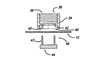
図3は、図2に示した照明装置の一部と、ヘッドウエア12の一部とを示している。ボトムハウジング34は、凹部36と、トップ部分に結合するように構成されたトップ結合部分38とを有している。トップ結合部分38には、一般的に、トップハウジング22のトップハウジング結合部30を受け入れるためのねじ山が形成されている。なお、トップハウジング結合部30及びトップ結合部38はねじ結合するように示されているが、他のタイプの結合構造を用いることができる。
FIG. 3 shows a part of the illumination device shown in FIG. 2 and a part of the
ボトムハウジング34は、開口部42を有するボトム結合部40を有している。ベース44は、ベース結合部46を有している。ベース結合部46は、一般的に、ボトムハウジング34とベース44を結合させるための、ボトム結合部40の開口部42と結合するように構成された突起部47を有している。なお、ボトムハウジング34とベース44を結合させるのには、様々な結合構造を用いることができる。
The
ベース44は、一般的に、突起部47がヘッドウエア12を貫通してベース44、ヘッドウエア12及びボトムハウジング34を結合するように、ヘッドウエア12の内側に配置される。このような構成により、照明装置をヘッドウエア12に結合させることができる。なお、ここで説明した方法に限らず、様々な結合構造を用いることができる。
The
図4は、ボトムハウジング34及びベース44と、結合位置にあるヘッドウエア12とを示している。ベース44は、ベース結合部46と突起部47とを有している。突起部47は、ヘッドウエア12を貫通してボトムハウジング34のボトム結合部40内にまで延出し、それらを結合する。
FIG. 4 shows the
図5は、図4の実施形態に、電力素子48を加えた状態を示している。電力素子48は、一般的に、ボトムハウジング34の凹部36に収容される。電力素子48がボトムハウジング34内に配置されると、ベース44をボトムハウジング34に固定すべく、電力素子48は突起部47を曲げるために下方に押し込まれる。このようにして、照明装置20の一部をヘッドウエア12に固定する。突起部47は、それらの結合が解けないように、離れる方向に曲げられる。
FIG. 5 shows a state where a
図6は、図5の実施形態に、トップハウジング22を加えた状態を示している。トップハウジング22は、一般的に、半透明部24、照明素子26及び制御回路28を有している。電力素子48は、一般的に、制御回路28及び照明素子26用に構成されている。半透明部24は、ほとんどの方角から(全部ではないかもしれないが)照明素子26の明かりが見えるように構成されている。
FIG. 6 shows a state in which a
照明素子26としては、一般的に、発光ダイオード(LED)が用いられる。しかし、望むのであれば、他の照明素子を用いることもできる。制御回路28は、一般的に、電力素子48から電力を供給され、照明素子26を明るくするときなどの全システムの動作を制御する。
As the
トップハウジング22は、一般的に、ボトムハウジング34のトップ結合部38と結合するよう構成されたトップハウジング結合部30を有している。電力素子48から制御回路28に電力を供給する際は、トップハウジング22を締め付け、電力を遮断する際は締め付けを緩める。なお、制御回路28及び照明素子26の電力をオン・オフするのには、アクチュエータ又はスイッチ構造などの他の構造を用いることもできる。
The
図7は、本発明の他の実施形態に係るライト付きヘッドウエアシステム50を示している。ライト付きヘッドウエアシステム50は、一般的に、ヘッドウエア52と照明装置60とを備えている。この実施形態では、ヘッドウエア52は、自転車用ヘルメットである。しかし、望むのであれば、他のタイプのヘッドウエアであってもよい。また、図7は、照明装置の他の実施形態を示している。
FIG. 7 shows a
図8は、ライト付きヘッドウエアシステム50の分解図である。この実施形態では、照明装置60は、シェル(shell)54と衝撃吸収部56との間に取り付けられる。このように構成することにより、ボトムハウジング70の結合構造74は、照明装置60をヘッドウエア52に結合させるべく、シェル54と衝撃吸収部56との間に配置される。なお、望むのであれば、他の結合構造を用いることもできる。
FIG. 8 is an exploded view of the
図9は、本発明の他の実施形態に係る照明装置60を示している。照明装置60は、一般的に、トップハウジング62とボトムハウジング70とを含んでいる。トップハウジング62は、一般的に、照明素子64、制御素子66及び電力素子68を有している。ボトムハウジング70は、一般的に、その内部に、照明素子64、制御回路66及び電力素子68を収容可能な凹部72を有している。
FIG. 9 shows an
照明装置60は、一般的に、長さ1〜4インチであり、高さ0.25〜2.0インチである。なお、望むのであれば、照明装置の形状及び構造は変更可能である。
The
トップハウジング62は、一般的に、凹部72に収容されるように構成されており、その内部にシステムの他の要素を保持すべく、及び分解を容易にすべく、締まりばめを形成している。さらに、トップハウジング62は、一般的に、照明素子64からの照明が外部に透過されるように半透明である。制御回路66は、トップハウジング62を下方に押し込んでスイッチ67を動作させ、制御回路66の電力を交互にオン・オフすることにより駆動される。なお、望むのであれば、他の作動構造を用いることもできる。さらに、トップハウジング62は、一般的に、ユーザがスイッチ67を動作できるように弾力性を有している。
The
照明素子64としては、一般的に、発光ダイオード(LED)が用いられる。しかし、望むのであれば、他の照明素子を用いることもできる。また、図9では2個の照明素子64が示されているが、望むのであれば、照明素子の数はいくつであってもよい。
As the
ボトムハウジング70は、一般的に、ヘッドウエア52と結合するように構成されたボトム結合構造74を有している。ボトム結合構造74は、一般的に、照明装置60をヘッドウエアに結合させるための開口部76を有している。
The
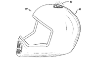
図10は、本発明の他の実施形態に係るライト付きヘッドウエアシステム90を示している。ライト付きヘッドウエアシステム90は、一般的に、ヘルメット92と照明装置60とを備えている。この実施形態では、ヘルメット92は、オートバイ用のヘルメット又は他のタイプのヘルメットである。
FIG. 10 shows a
図11は、照明装置60をヘルメット92に取り付ける方法を示している。結合構造74には孔76が形成されており、この実施形態では、ボルト78が孔76及びヘルメット92を貫通して、ナット82(ねじが切られており、ボルト78を受け入れるように構成されている)によってヘルメット92に固定される。なお、ここでは、照明装置60とヘルメット92はボルト・ナット構造によって固定しているが、望むのならば、例えば、接着剤、リベット又は他の結合構造などの他の方法を用いることもできる。
FIG. 11 shows a method of attaching the
上記に説明及び開示した様々な実施形態では、照明装置60は、当業者なら理解できるように、その周囲360°を照射する。又は、遮蔽することにより小規模に光を放つ。
In the various embodiments described and disclosed above, the
以上、本発明の特定の実施形態について説明したが、本発明は前記した実施の形態のみに限定されるものではなく、本発明の技術的思想に基づく限りにおいて、種々の変形が可能である。 Although specific embodiments of the present invention have been described above, the present invention is not limited to the above-described embodiments, and various modifications can be made as long as they are based on the technical idea of the present invention.
Claims (13)
クラウン部分と、前記クラウン部分に動作可能に結合された照明装置とを有し、
前記照明装置は、
少なくとも1つの照明素子及び少なくとも1つの電力源を受け入れるように構成され、少なくとも1つの開口部を有するクラウン接合部分を含む第1ハウジングと、
前記開口部と嵌合したときに前記クラウン部分から離反する向きに延出するように構成された少なくとも1つの突起部を有する基部とを含み、
前記第1ハウジング内で前記少なくとも1つの前記電力源を押し込んだときに、前記延出した突起部は、前記第1ハウジングを前記クラウン部分に固定すべく、前記少なくとも1つの電力源によって前記クラウン部分に向けて折り曲げられ、前記クラウン部分は、前記基部と前記第1ハウジングの前記クラウン接合部との間にしっかりと挟み込まれることを特徴とするヘッドウエア。Headwear with light,
A crown portion and a lighting device operably coupled to the crown portion;
The lighting device includes:
A first housing configured to receive at least one illumination element and at least one power source and including a crown joint having at least one opening;
A base having at least one protrusion configured to extend away from the crown portion when mated with the opening.
When the at least one power source is pushed into the first housing, the extended protrusion is adapted to secure the first housing to the crown portion by the at least one power source. And the crown portion is firmly sandwiched between the base portion and the crown joint portion of the first housing.
前記第1ハウジングを前記クラウン部分から分離させるときは、前記電力源を前記第1ハウジングから除去した後に、前記少なくとも1つの突起部を前記クラウン部分から遠ざかる方向に曲げることを特徴とするヘッドウエア。The headwear with light according to claim 1,
When the first housing is separated from the crown part, the at least one protrusion is bent in a direction away from the crown part after the power source is removed from the first housing.
前記電力源はバッテリーであることを特徴とするヘッドウエア。The headwear with light according to claim 1,
Headwear, wherein the power source is a battery.
前記照明素子はLED(発光ダイオード)であることを特徴とするヘッドウエア。The headwear with light according to claim 1,
Headwear, wherein the illumination element is an LED (light emitting diode).
前記クラウン部分は内面及び外面を有し、前記基部は前記クラウン部分の前記内面に対向して配置されることを特徴とするヘッドウエア。The headwear with light according to claim 1,
The crown portion has an inner surface and an outer surface, and the base portion is disposed to face the inner surface of the crown portion.
前記第1ハウジングは前記クラウン部分の前記外面に対向して配置されることを特徴とするヘッドウエア。The headwear with light according to claim 8,
The headwear, wherein the first housing is disposed to face the outer surface of the crown portion.
前記第1ハウジングは、実質的に、前記クラウン部分の前記外面の頂上部において前記基部に固定されることを特徴とするヘッドウエア。The headwear with light according to claim 9,
The headwear is characterized in that the first housing is substantially fixed to the base at the top of the outer surface of the crown portion.
前記クラウン部分は、前記野球帽の一部であることを特徴とするヘッドウエア。The headwear with light according to claim 1,
The headwear, wherein the crown portion is a part of the baseball cap.
前記第2ハウジングは、前記電力源及び照明素子間に動作可能に結合された制御回路をさらに有することを特徴とするヘッドウエア。The headwear with light according to claim 4,
The headwear further comprising a control circuit operably coupled between the power source and the lighting element.
前記制御回路は、前記第2ハウジングを前記第1ハウジングに締め付けることによって電力を供給されることを特徴とするヘッドウエア。A headwear with a light according to claim 12,
The headwear is characterized in that the control circuit is supplied with electric power by fastening the second housing to the first housing.
Applications Claiming Priority (2)
| Application Number | Priority Date | Filing Date | Title |
|---|---|---|---|
| US10/612,023 US6941583B2 (en) | 2003-07-01 | 2003-07-01 | Illuminated headwear |
| PCT/US2004/021426 WO2005002379A2 (en) | 2003-07-01 | 2004-06-28 | Lighted headwear |
Publications (2)
| Publication Number | Publication Date |
|---|---|
| JP2007535093A JP2007535093A (en) | 2007-11-29 |
| JP4470210B2 true JP4470210B2 (en) | 2010-06-02 |
Family
ID=33564257
Family Applications (1)
| Application Number | Title | Priority Date | Filing Date |
|---|---|---|---|
| JP2006517845A Active JP4470210B2 (en) | 2003-07-01 | 2004-06-28 | Lighted headwear |
Country Status (9)
| Country | Link |
|---|---|
| US (1) | US6941583B2 (en) |
| EP (1) | EP1638425B1 (en) |
| JP (1) | JP4470210B2 (en) |
| KR (1) | KR20060030071A (en) |
| CN (1) | CN1794927A (en) |
| AU (1) | AU2004253575B2 (en) |
| CA (1) | CA2525586A1 (en) |
| DE (1) | DE602004027243D1 (en) |
| WO (1) | WO2005002379A2 (en) |
Families Citing this family (28)
| Publication number | Priority date | Publication date | Assignee | Title |
|---|---|---|---|---|
| US7184759B2 (en) * | 2001-07-26 | 2007-02-27 | Kyocera Wireless Corp. | Modular software components for wireless communication devices |
| US8388164B2 (en) * | 2005-05-17 | 2013-03-05 | Michael Waters | Hands-Free lighting devices |
| US20050229290A1 (en) * | 2004-04-20 | 2005-10-20 | Collegiate Usa | Light reflective headwear |
| US9526292B2 (en) | 2005-05-17 | 2016-12-27 | Michael Waters | Power modules and headgear |
| US20070022514A1 (en) * | 2005-07-28 | 2007-02-01 | Steven Paulson | Baseball cap attachment assembly |
| US20080198579A1 (en) * | 2006-03-02 | 2008-08-21 | Lineweight Llc | Hat Light |
| US7866066B2 (en) * | 2007-04-13 | 2011-01-11 | Forbes Brandon F | Footwear device with scrolling light emitting diode display |
| US8757831B2 (en) * | 2007-12-18 | 2014-06-24 | Michael Waters | Headgear having an electrical device and power source mounted thereto |
| WO2009079656A2 (en) * | 2007-12-18 | 2009-06-25 | Michael Waters | Hands-free lighting devices |
| US8491145B2 (en) * | 2007-12-18 | 2013-07-23 | Waters Industries, Inc. | Illuminated headgear having switch devices and packaging therefor |
| US20090288317A1 (en) * | 2008-05-23 | 2009-11-26 | Forbes Brandon F | Footwear device with scrolling light emitting diode display |
| US7959315B2 (en) * | 2008-08-06 | 2011-06-14 | Suen Ching Yan | Interchangeable illuminated ornament |
| DE212010000023U1 (en) * | 2009-02-27 | 2012-01-24 | Michael Waters | Lighting headgear |
| CA2797973A1 (en) | 2010-04-30 | 2011-11-03 | Michael Waters | Hands free lighting devices |
| US10028543B2 (en) | 2011-01-31 | 2018-07-24 | Darryl William Munns | Safety light helmet |
| CA2794370A1 (en) | 2011-11-04 | 2013-05-04 | Michael Waters | Hat with automated shut-off feature for electrical devices |
| US9609902B2 (en) | 2011-12-23 | 2017-04-04 | Michael Waters | Headgear having a camera device |
| US9526287B2 (en) | 2011-12-23 | 2016-12-27 | Michael Waters | Lighted hat |
| US9568173B2 (en) | 2011-12-23 | 2017-02-14 | Michael Waters | Lighted hat |
| US8967824B2 (en) * | 2012-05-15 | 2015-03-03 | Charles B. Hootman | Portable light having a modular base |
| WO2014100477A1 (en) | 2012-12-19 | 2014-06-26 | Michael Waters | Lighted solar hat |
| US9717633B2 (en) | 2013-03-15 | 2017-08-01 | Michael Waters | Lighted headgear |
| USD770143S1 (en) | 2014-05-23 | 2016-11-01 | Michael Waters | Beanie with means for illumination |
| USD757317S1 (en) * | 2015-06-01 | 2016-05-24 | John Junior Henry | Helmet emitter |
| US20170122506A1 (en) * | 2015-10-30 | 2017-05-04 | Dale Collins | Personal Safety Light |
| RU2694526C1 (en) * | 2018-03-26 | 2019-07-16 | Федеральное государственное казенное военное образовательное учреждение высшего образования "Военный университет" Министерства обороны Российской Федерации | Tactical cap for night use |
| US10791783B1 (en) | 2019-05-16 | 2020-10-06 | Waters Industries, Inc. | Lighted headgear and accessories therefor |
| USD1013283S1 (en) * | 2021-03-09 | 2024-01-30 | Catherine Mae Olson | Helmet accessory dome light |
Family Cites Families (28)
| Publication number | Priority date | Publication date | Assignee | Title |
|---|---|---|---|---|
| US2640980A (en) * | 1950-12-11 | 1953-06-02 | Ralph G Grossman | Illuminated head covering |
| US2788439A (en) * | 1956-02-14 | 1957-04-09 | Gilbert S Hesse | Portable dome light |
| US3032647A (en) * | 1959-01-22 | 1962-05-01 | Wansky Morris Harold | Cap or hat light |
| US3358137A (en) * | 1965-11-22 | 1967-12-12 | Sinclair Fraser Corp | Illuminated safety helmet |
| US3749902A (en) * | 1971-07-28 | 1973-07-31 | J Drew | Safety equipment for rescue workers, traffic policemen and the like |
| US3963917A (en) * | 1975-03-07 | 1976-06-15 | Lawrence Peska Associates, Inc. | Illuminated safety helmet |
| US4186429A (en) * | 1976-05-19 | 1980-01-29 | Johnston Walter A | Flashing light safety device for cyclists helmets |
| US4090232A (en) * | 1977-08-24 | 1978-05-16 | Douglas Golden | Illumination means for the head |
| USD318338S (en) | 1989-01-04 | 1991-07-16 | Mitchell Robert E | Illuminated cap |
| US4991068A (en) * | 1990-02-14 | 1991-02-05 | Mickey Scott A | Lamp attachment for hat |
| US5404593A (en) * | 1993-02-18 | 1995-04-11 | American Needle | Headwear piece with ornamental illumination |
| US5363291A (en) * | 1993-11-01 | 1994-11-08 | New Erra Group, Inc. | Portable light assembly |
| US5680718A (en) * | 1994-12-20 | 1997-10-28 | First Choice Trading Limited | Illuminable hat |
| US5510961A (en) * | 1995-05-31 | 1996-04-23 | Peng; Yu-Lin | Cap structure with sound recording and generating functions and warning lights |
| US5541816A (en) * | 1995-06-07 | 1996-07-30 | Miserendino; Nicholas G. | Clip light source |
| US5741060A (en) * | 1996-08-28 | 1998-04-21 | Johnson; Thomas R. | Baseball cap light |
| US5845987A (en) * | 1996-10-08 | 1998-12-08 | Painter; John M. | Illuminated accessory and device |
| US6113244A (en) * | 1997-05-28 | 2000-09-05 | Baumgartner; Michael P. | Fiber optic lighted helmet |
| USD407187S (en) | 1997-12-08 | 1999-03-30 | Farhad Seyed Makki | Cap with lights |
| US6244721B1 (en) * | 1997-12-24 | 2001-06-12 | Mark F. Rodriguez | Illuminated helmet device |
| US6056413A (en) * | 1997-12-29 | 2000-05-02 | Urso; Charles L. | Cap lamp |
| US6168286B1 (en) * | 1998-08-03 | 2001-01-02 | Paul J. Duffy | Brim mounted novelty light for sports caps |
| US6032293A (en) | 1998-08-05 | 2000-03-07 | Makki; Farhad Seyed | Hat ornamental illumination circuit accessory |
| US6328454B1 (en) * | 1998-11-23 | 2001-12-11 | Keith Davis | Safety lighting |
| US6461015B1 (en) * | 1999-03-25 | 2002-10-08 | Charles D. Welch | Portable wearable strobe light |
| EP1072204A3 (en) | 1999-07-23 | 2002-07-24 | Chang Sung Lim | Cap having a lantern |
| US20020118533A1 (en) * | 2000-09-27 | 2002-08-29 | Jez Marston | Illuminated cap and shoe set |
| US6616293B2 (en) * | 2001-04-26 | 2003-09-09 | Scott Alan Mickey | Lighted hat devices with rotatable switch feature |
-
2003
- 2003-07-01 US US10/612,023 patent/US6941583B2/en not_active Expired - Fee Related
-
2004
- 2004-06-28 KR KR1020057025490A patent/KR20060030071A/en not_active Application Discontinuation
- 2004-06-28 CN CNA2004800146652A patent/CN1794927A/en active Pending
- 2004-06-28 JP JP2006517845A patent/JP4470210B2/en active Active
- 2004-06-28 WO PCT/US2004/021426 patent/WO2005002379A2/en active Application Filing
- 2004-06-28 AU AU2004253575A patent/AU2004253575B2/en not_active Ceased
- 2004-06-28 DE DE602004027243T patent/DE602004027243D1/en active Active
- 2004-06-28 CA CA002525586A patent/CA2525586A1/en not_active Abandoned
- 2004-06-28 EP EP04756630A patent/EP1638425B1/en not_active Expired - Fee Related
Also Published As
| Publication number | Publication date |
|---|---|
| KR20060030071A (en) | 2006-04-07 |
| DE602004027243D1 (en) | 2010-07-01 |
| AU2004253575A1 (en) | 2005-01-13 |
| WO2005002379B1 (en) | 2005-09-01 |
| EP1638425B1 (en) | 2010-05-19 |
| US6941583B2 (en) | 2005-09-13 |
| AU2004253575B2 (en) | 2009-12-17 |
| WO2005002379A2 (en) | 2005-01-13 |
| JP2007535093A (en) | 2007-11-29 |
| WO2005002379A3 (en) | 2005-07-21 |
| CN1794927A (en) | 2006-06-28 |
| EP1638425A2 (en) | 2006-03-29 |
| US20050066422A1 (en) | 2005-03-31 |
| EP1638425A4 (en) | 2007-01-31 |
| CA2525586A1 (en) | 2005-01-13 |
Similar Documents
| Publication | Publication Date | Title |
|---|---|---|
| JP4470210B2 (en) | Lighted headwear | |
| US7267453B2 (en) | Multifunctional stick assembly | |
| US20170184260A1 (en) | Portable Solar Light That Can Be Secured To Functional Accessories That Can Be Illuminated | |
| US20050157503A1 (en) | Low-power high-intensity lighting apparatus | |
| US8517556B2 (en) | Helmet mounted lighting apparatus and method of manufacture | |
| KR200458200Y1 (en) | Difficult to decompose and Moving cover LED ceiling lamp | |
| USD515118S1 (en) | Sight with a light emitting device | |
| JP5678159B1 (en) | LED lighting device | |
| CN207298764U (en) | A kind of LED candle lamp | |
| US11078057B2 (en) | Remote controller | |
| US6860627B2 (en) | Special-purpose light-guiding seat for pilot lamps of an electronic machine | |
| JP2014060069A (en) | Lighting equipment | |
| KR200266596Y1 (en) | High efficient search light which has siren device | |
| JPH0338884Y2 (en) | ||
| KR101274281B1 (en) | Led warning light | |
| US11112066B2 (en) | Laser light installed inside cavity of bulb lamp and method of assembling laser light inside cavity of bulb lamp | |
| JP3100113U (en) | Mounting structure of high-intensity discharge bulb for vehicles | |
| CN218295388U (en) | Multifunctional outdoor lighting device | |
| CN218895295U (en) | Gesture induction head lamp | |
| GB2490371A (en) | Lamp device | |
| CN211526290U (en) | Multifunctional LED lamp | |
| CN219414564U (en) | Multifunctional ship lamp device | |
| CN107246587A (en) | A kind of LED candle lamp | |
| CN210319769U (en) | Decorative lamp | |
| US20050078470A1 (en) | Megaphone |
Legal Events
| Date | Code | Title | Description |
|---|---|---|---|
| TRDD | Decision of grant or rejection written | ||
| A01 | Written decision to grant a patent or to grant a registration (utility model) |
Free format text: JAPANESE INTERMEDIATE CODE: A01 Effective date: 20100126 |
|
| A01 | Written decision to grant a patent or to grant a registration (utility model) |
Free format text: JAPANESE INTERMEDIATE CODE: A01 |
|
| A61 | First payment of annual fees (during grant procedure) |
Free format text: JAPANESE INTERMEDIATE CODE: A61 Effective date: 20100219 |
|
| FPAY | Renewal fee payment (event date is renewal date of database) |
Free format text: PAYMENT UNTIL: 20130312 Year of fee payment: 3 |
|
| R150 | Certificate of patent or registration of utility model |
Free format text: JAPANESE INTERMEDIATE CODE: R150 |