JP4468995B2 - Portable electronic devices for image capture - Google Patents
Portable electronic devices for image capture Download PDFInfo
- Publication number
- JP4468995B2 JP4468995B2 JP2007555716A JP2007555716A JP4468995B2 JP 4468995 B2 JP4468995 B2 JP 4468995B2 JP 2007555716 A JP2007555716 A JP 2007555716A JP 2007555716 A JP2007555716 A JP 2007555716A JP 4468995 B2 JP4468995 B2 JP 4468995B2
- Authority
- JP
- Japan
- Prior art keywords
- reflector
- electronic device
- camera
- movable
- illumination member
- Prior art date
- Legal status (The legal status is an assumption and is not a legal conclusion. Google has not performed a legal analysis and makes no representation as to the accuracy of the status listed.)
- Expired - Fee Related
Links
Images


Classifications
-
- H—ELECTRICITY
- H04—ELECTRIC COMMUNICATION TECHNIQUE
- H04M—TELEPHONIC COMMUNICATION
- H04M1/00—Substation equipment, e.g. for use by subscribers
- H04M1/02—Constructional features of telephone sets
- H04M1/0202—Portable telephone sets, e.g. cordless phones, mobile phones or bar type handsets
- H04M1/0206—Portable telephones comprising a plurality of mechanically joined movable body parts, e.g. hinged housings
- H04M1/0208—Portable telephones comprising a plurality of mechanically joined movable body parts, e.g. hinged housings characterized by the relative motions of the body parts
- H04M1/0214—Foldable telephones, i.e. with body parts pivoting to an open position around an axis parallel to the plane they define in closed position
- H04M1/0216—Foldable in one direction, i.e. using a one degree of freedom hinge
- H04M1/0218—The hinge comprising input and/or output user interface means
-
- H—ELECTRICITY
- H04—ELECTRIC COMMUNICATION TECHNIQUE
- H04M—TELEPHONIC COMMUNICATION
- H04M1/00—Substation equipment, e.g. for use by subscribers
- H04M1/02—Constructional features of telephone sets
- H04M1/0202—Portable telephone sets, e.g. cordless phones, mobile phones or bar type handsets
- H04M1/026—Details of the structure or mounting of specific components
- H04M1/0264—Details of the structure or mounting of specific components for a camera module assembly
-
- H—ELECTRICITY
- H04—ELECTRIC COMMUNICATION TECHNIQUE
- H04N—PICTORIAL COMMUNICATION, e.g. TELEVISION
- H04N23/00—Cameras or camera modules comprising electronic image sensors; Control thereof
- H04N23/56—Cameras or camera modules comprising electronic image sensors; Control thereof provided with illuminating means
-
- H—ELECTRICITY
- H04—ELECTRIC COMMUNICATION TECHNIQUE
- H04N—PICTORIAL COMMUNICATION, e.g. TELEVISION
- H04N23/00—Cameras or camera modules comprising electronic image sensors; Control thereof
- H04N23/58—Means for changing the camera field of view without moving the camera body, e.g. nutating or panning of optics or image sensors
-
- H—ELECTRICITY
- H04—ELECTRIC COMMUNICATION TECHNIQUE
- H04M—TELEPHONIC COMMUNICATION
- H04M2250/00—Details of telephonic subscriber devices
- H04M2250/20—Details of telephonic subscriber devices including a rotatable camera
Landscapes
- Engineering & Computer Science (AREA)
- Signal Processing (AREA)
- Multimedia (AREA)
- Human Computer Interaction (AREA)
- Studio Devices (AREA)
- Stroboscope Apparatuses (AREA)
- Telephone Set Structure (AREA)
- Photographic Developing Apparatuses (AREA)
- Printers Or Recording Devices Using Electromagnetic And Radiation Means (AREA)
Abstract
Description
本発明の実施形態は、画像を撮影するための携帯用電子デバイスに関する。特に、デバイスの本体に対して複数の方向で画像を撮影するための携帯用電子デバイスに関する。 Embodiments of the present invention relate to portable electronic devices for taking images. In particular, the present invention relates to a portable electronic device for taking images in a plurality of directions with respect to the main body of the device.
カメラは、被写体から開口部に入る光を記録することで画像を撮影する。低光量の状況下で画質を高めるために、電子フラッシュを使用するカメラが多い。電子フラッシュは、画像を撮影するときに画像の撮影方向から光を一斉に放出して画質を高める仕組みになっている。 The camera captures an image by recording light entering the opening from the subject. Many cameras use electronic flash to improve image quality under low light conditions. The electronic flash is designed to enhance image quality by emitting light all at once from the image capturing direction when capturing an image.
最近のデバイスでは、可動式のカメラ部品が使用されることもある。該カメラ部品は、使用者がデバイスの本体に対して複数の方向から画像を撮影できるよう、軸を中心に回転することができる。ビデオ通話中には移動電話の使用者の方にカメラを向けることができ、別の場合には使用者から離れる方向に向けて画像を撮影することができるため、回転式カメラは移動電話で特に多く用いられる。 In modern devices, movable camera parts may be used. The camera component can rotate about an axis so that the user can take images from multiple directions with respect to the body of the device. During video calls, the camera can be pointed towards the mobile phone user, and in other cases the camera can be taken away from the user, so the rotary camera is especially useful on mobile phones. Often used.
加えて、このような回転式カメラ開口部を内蔵した携帯用電子デバイスには、低光量の状況下で画像を撮影するときに開口部に入る光のレベルを高めるために、照明部材が内蔵されていることもある。照明部材は通常、電話の筐体内のある位置に固定された白色LEDである。異なる方向で画像を撮影するために使用者がカメラを回転させた場合、照明部材から放出される光の方向が、画像の撮影方向と一致しなくなることもある。そのため、そのような画像を撮影する場合には、照明部材を使用できないこともある。 In addition, such portable electronic devices with built-in rotary camera openings have built-in illumination members to increase the level of light entering the openings when taking images under low light conditions. Sometimes. The illuminating member is typically a white LED that is fixed in a position within the telephone housing. When the user rotates the camera to capture an image in a different direction, the direction of light emitted from the illumination member may not match the image capturing direction. Therefore, when photographing such an image, the illumination member may not be used.
代わりに使用者は、デバイス全体を回転させて異なる方向から画像を撮影することに決める場合もある。しかしその結果、使用者がディスプレイを見られなくなることもある。 Instead, the user may decide to rotate the entire device and take images from different directions. However, as a result, the user may not be able to see the display.
電子フラッシュを駆動するために、フラッシュ回路が使用される。これまでは、フラッシュ管に高い電流および電圧が必要であることを考慮して、可動接触子の使用を避けるために、フラッシュ回路全体を可動式フラッシュ部品内に入れることが提案されてきた。しかしこれは、主コンデンサなどフラッシュ回路の一部の構成要素のサイズが原因となって、可動式フラッシュ部品の大型化につながる。 A flash circuit is used to drive the electronic flash. In the past, in view of the high current and voltage requirements of the flash tube, it has been proposed to place the entire flash circuit in a movable flash part to avoid the use of movable contacts. However, this leads to an increase in the size of the movable flash part due to the size of some components of the flash circuit such as the main capacitor.
本発明の第1の態様によれば、本体を有する電子デバイスであって、前記デバイスが、前記デバイスの前記本体に対して複数の方向で画像を撮影するためのカメラ装置と、照明部材と、前記照明部材から反射される光の前記方向を変更するために、少なくとも一部分が前記照明部材を中心に移動可能である反射体と、電圧を供給して前記照明部材を動作させる電源と、前記電源を前記反射体に電気的に接続して、電圧を前記反射体に印加して前記照明部材を動作させる、コネクタとを含み、前記コネクタと前記反射体との間の接続点が、前記照明部材を中心とした前記反射体の移動に伴って変化し得る、電子デバイスが提供される。 According to a first aspect of the present invention, there is provided an electronic device having a main body, wherein the device captures an image in a plurality of directions with respect to the main body of the device, an illumination member, In order to change the direction of the light reflected from the lighting member, a reflector at least a part of which is movable around the lighting member, a power source for operating the lighting member by supplying a voltage, and the power source Is connected to the reflector, and a voltage is applied to the reflector to operate the illumination member. A connection point between the connector and the reflector includes the illumination member. An electronic device is provided that can change as the reflector moves around the center.
カメラ装置は、画像の撮影方向を変更するために、本体に対して移動可能である開口部を備えたカメラを含めばよい。カメラ開口部は、使用者により移動可能であるとよい。カメラ開口部は、回転により移動可能であるとよい。 The camera device may include a camera having an opening that is movable with respect to the main body in order to change the image capturing direction. The camera opening may be movable by the user. The camera opening may be movable by rotation.
反射体は、使用者により移動可能であるとよい。反射体は、照明部材を中心とした回転により移動可能であるとよい。カメラ開口部および反射体は、ほぼ平行な軸を中心とした回転により移動可能であってもよい。カメラ開口部および反射体は、実質的に同一の軸を中心とした回転により移動可能であってもよい。 The reflector may be movable by the user. The reflector may be movable by rotating around the illumination member. The camera opening and the reflector may be movable by rotation about a substantially parallel axis. The camera opening and the reflector may be movable by rotation about substantially the same axis.
デバイスは、反射体とカメラ装置との間で機能する連結手段をさらに含み、カメラ開口部の移動が反射体の移動を引き起こす仕組みになっているとよい。連結手段は、画像の撮影方向と、反射体の使用時に反射される光の方向とがほぼ一致するカメラ開口部の位置を、少なくとも2つ提供する仕組みであればよい。 The device may further include a connecting unit that functions between the reflector and the camera device, and the movement of the camera opening may cause the movement of the reflector. The connecting means may be a mechanism that provides at least two camera opening positions where the image capturing direction and the direction of the light reflected when the reflector is used substantially coincide.
カメラ装置は、第1の方向、および第1の方向とほぼ反対の第2の方向で画像を撮影するものであればよい。反射体は、曲面状の表面を有するとよい。反射体は、放物面状であるとよい。照明部材は長形部分を有するとよく、その長形部分を中心に反射体が移動可能であるとよい。 The camera device may be any device that captures images in the first direction and the second direction substantially opposite to the first direction. The reflector may have a curved surface. The reflector is preferably parabolic. The illuminating member may have a long portion, and the reflector may be movable around the long portion.
照明部材は、本体に固定配置されるとよい。デバイスは、照明部材を作動させるためにデバイスの本体に固定配置された駆動回路をさらに含むとよい。 The illumination member may be fixedly disposed on the main body. The device may further include a drive circuit fixedly disposed on the body of the device for actuating the lighting member.
照明部材は、キセノン管を含めばよい。反射体に電圧を印加することでキセノンを少なくとも部分的にイオン化できるとよい。 The illumination member may include a xenon tube. Xenon may be at least partially ionized by applying a voltage to the reflector.
反射体は、相対移動をする仕組みの、協働する別々の反射部品を2つ含んでもよい。反射体の第1の部品は照明部材を中心に回転可能であるとよく、反射体の第2の部品はデバイスの本体に対して固定されているとよい。反射体の第2の固定部品と電源との間の電気的接続は、反射体の第2の固定部品において固定接続点を有すればよい。 The reflector may include two separate reflective components that cooperate to move relative to each other. The first part of the reflector may be rotatable about the illumination member, and the second part of the reflector may be fixed relative to the body of the device. The electrical connection between the second fixed component of the reflector and the power supply may have a fixed connection point in the second fixed component of the reflector.
本発明の第2の態様によれば、照明部材を中心に反射体の少なくとも一部分を移動して前記照明部材からの光の方向を変更し、コネクタと前記反射体との間の接続点を変化させる工程であって、前記コネクタは、電源を前記反射体に電気的に接続し、前記電源は、電圧を前記反射体に印加して前記照明部材を動作させるよう動作可能である工程と、前記照明部材から向けられた前記光を使用して前記カメラ装置で画像を撮影する工程とを含む方法が提供される。 According to the second aspect of the present invention, at least a part of the reflector is moved around the illumination member to change the direction of light from the illumination member, and the connection point between the connector and the reflector is changed. The connector electrically connects a power source to the reflector, and the power source is operable to apply a voltage to the reflector to operate the illumination member; and And taking a picture with the camera device using the light directed from a lighting member.
カメラ装置は、反射体により方向づけられた光の方向と一致するように、画像の撮影方向を変更するよう調整されればよい。 The camera device may be adjusted so as to change the shooting direction of the image so as to coincide with the direction of light directed by the reflector.
本発明の第3の態様によれば、カメラの照明装置であって、照明部材と、第1部分及び第2部分を有する反射体であって、前記第1部分は前記第2部分および前記照明部材に対して移動可能であって、前記照明部材によって照明が提供される隙間を前記反射体に位置づける反射体とを含むカメラの照明装置が提供される。
本発明の第4の態様によれば、反射体の第1部分を照明体及び反射体の第2部分に対して移動させて、前記照明部材によって照明が提供される隙間を前記反射体に位置づける工程と、前記照明部材からの照明を使用して前記カメラ装置で画像を撮影する工程とを含む方法が提供される。
According to a third aspect of the present invention, there is provided an illumination device for a camera, the illumination member and a reflector having a first portion and a second portion, wherein the first portion is the second portion and the illumination. An illumination device for a camera is provided that includes a reflector that is movable relative to the member and that positions a gap in the reflector that is illuminated by the illumination member.
According to the 4th aspect of this invention, the 1st part of a reflector is moved with respect to the 2nd part of an illuminating body and a reflector, and the clearance gap where illumination is provided by the said illumination member is located in the said reflector. There is provided a method comprising the steps of: taking an image with the camera device using illumination from the illumination member.
本発明の理解を深めるために、ここからは例示のみを目的として添付の図面を参照する。 For a better understanding of the present invention, reference will now be made by way of example only to the accompanying drawings in which:
図面は、本体42を有する携帯用電子デバイス100/200/300を示す。デバイス100/200/300は、デバイス100/200/300の本体42に対して複数の方向から画像を撮影するためのカメラ装置32、照明部材14、および照明部材14から反射される光の方向を変更するために少なくとも一部分が照明部材14を中心に移動可能である反射体12を含む。
The drawing shows a portable
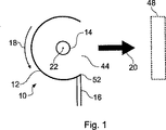
図1および2は、デバイス100/200/300用のフラッシュユニット10を示す。フラッシュユニット10は、放物面反射体12、照明部材14、電気コネクタ16および電気コネクタ22を含む。通常、照明部材14はキセノン管である。キセノン管14は、使用者がより質の高い画像を撮影できるように、画像の撮影時に高輝度の閃光を生じさせるために使用される。部材14から生成された光を被写体の方へ向けるために、反射体12が使用される。
1 and 2 show a
キセノン管14を使用して光を生成するには、管内のキセノンガス混合物がイオン化される必要がある。イオン化は、超高電圧(数千ボルトなど)、低電流のトリガパルスを管14の付近に印加することで実現できる。キセノンガスがイオン化されると、電流はコネクタ22の間にある管14を流れることができ、これによりキセノンが光を生成する。キセノン管14内のキセノンをイオン化するために使用される電圧は、「トリガ電圧」として広く知られている。
In order to generate light using the
図1および2では、金属製か、または金属化された反射体12にトリガ電圧が印加される。電圧は、電気コネクタ16を使用して印加される。そのため、この場合反射体12は「トリガプレート(trigger plate)」としても機能する。コネクタ22の間のキセノン管14を流れる電流は、トリガプレートが伝える電流よりも大幅に高い。
1 and 2, a trigger voltage is applied to a
図1および2に示された実施形態では、照明部材14は、長円筒形のキセノン管である。反射体12は細長く曲面状で、隙間44を残して管14の周りに位置している。光は放射状に管14を出るが、反射体12の隙間44を直接通過しない光はすべて隙間44の方へ反射される。管14および反射体12は、大きな矢印20が示す全体的な方向へ光が出ていくように配置されている。
In the embodiment shown in FIGS. 1 and 2, the
管14と反射体12との相対的配置、反射体12の曲率および隙間44の大きさなどの、管14および反射体12の幾何的配置を利用して、隙間44から放出される光線の構造を設定できる。例えば、反射体12の隙間44が大きくなるほど、隙間44から放出される光線は太くなる。加えて、フラッシュユニット10は、光が隙間44から放出された後にその光を方向づけるために、レンズ48を含んでもよい。
The structure of rays emitted from the
反射体12は、方向20を変更するために、キセノン管14を中心として、管14に対して矢印18の方向に回転可能である。フラッシュユニットがレンズ48を含む場合、レンズ48も反射体12と共に回転するとよい。
The
図1および2のどちらにおいても、反射体12が少なくとも180°回転できるということがわかる。そのため、使用者は、反射体12を回転させることで、フラッシュユニット10全体を回転する必要なく、選択した場所に光を向けることもできる。
It can be seen in both FIGS. 1 and 2 that the
反射体12が回転する間、コネクタ16の位置は固定されたままである。したがって、反射体12はコネクタ16に対して回転することとなり、その結果、コネクタ16と反射体12との間の接続点52は反射体12の移動に伴い変化するが、それでも反射体12にトリガ電圧を印加する能力は、反射体が移動している間も保持される。
While the
反射体12とフラッシュ回路80との間の接続部は、超高電圧(トリガ電圧)、低電流を伝える必要がある。そのため、図1および2に示されるような摺動コネクタ16が適切となる。
The connection between the
反射体12に接続される電気コネクタ16、およびキセノン管14に接続される電極22は、すべてデバイス100/200/300内のフラッシュ回路80に接続される(図4〜6を参照のこと)。フラッシュ回路80は、フラッシュがトリガされた後に、反射体12に印加される高いトリガ電圧、加えて、コネクタ22に必要な電流を生成するために使用される。
The
図3は、さらに接続レール24も含むフラッシュユニット10を示す。接続レール24を組み込むことで、コネクタ16との接続を維持しながら、反射体12を管14の軸に対して360°回転させることもできる。このようにすると、反射体12のどの位置でも管14をトリガできる。
FIG. 3 shows the
管14に対して反射体12を旋回させることで、管14が旋回する必要なく、さらに反射体12にトリガ電圧を印加する能力を失うこともなく方向20を変更できることが、これらの各例からわかる。
From each of these examples, turning the
図4は、2つ折り手持ち式携帯用無線電話(hand portable radio telephone)100に、図1、2または3のフラッシュユニット10がどのように内蔵されればよいかを示す。無線電話100は通信回路を含み、これによって、当技術分野で知られるとおりセルラーネットワークで電話として動作できる。無線電話100は、第1の筐体110および第2の筐体112を有する。第1および第2の筐体110、112は、ヒンジ26により回転可能な状態で接続されている。第1の筐体110はディスプレイ60および受話口90を含み、第2の筐体112はキーパッド94およびマイクロホン92を含む。フラッシュ回路80は、第2の筐体112に固定配置されている。
FIG. 4 shows how the
ヒンジ26は、開口部33を備えたカメラ筐体32を含む。筐体32に収容されたカメラは、開口部33をとおして画像を撮影するために使用される。カメラ筐体32は、矢印36の方向に回転できる。したがって、開口部33をとおしてカメラにより画像が撮影される方向は、デバイス100に対して変更できる。具体的な例を挙げると、使用者がディスプレイ60を見ながらキーパッド94を操作するようにデバイス100を持っているとき、使用者側および使用者から逆側という、180°離れた少なくとも2つの方向で画像を撮影できる。
The
フラッシュ筐体34は、反射体12を収容している。フラッシュ管14は、筐体112に取り付けられ、フラッシュ筐体34内へ延在している。加えて、フラッシュ筐体34は、上述の様に反射体12を管14を中心に回転させながら、矢印36の方向に回転できる。フラッシュ筐体34は、隙間44の位置と一致する窓40を含む。その結果、筐体34の回転により、光が生成される方向20が変化する。
The
フラッシュ筐体34は、カメラが画像を撮影できるのと同じ方向範囲に光を向けるよう旋回でき、被写体に常に照明を当てられることが好ましい。具体的には、筐体34は、使用者がディスプレイ60を見ているときに使用者側へ向かう第1の方向に向けられた位置と、第1の方向とほぼ反対の第2の方向であり、使用者がディスプレイ60を見ているときに使用者から逆側である第2の方向に向けられたもう1つの位置との、少なくとも2つの利用可能な位置を有することが好ましい。移動止めまたはラッチ機構を備えることで、フラッシュ筐体34およびカメラ筐体32がこれらの位置に保持されるようにするとよい。
The
その結果、カメラ筐体32およびフラッシュ筐体34が、使用者が自身の写真を撮りたいときは使用者の方に向き、他のものの写真を撮りたいときは使用者から逆側に向くようにすればよい。デバイス100の位置は変わらず、スクリーン60を見やすい状態が維持される。なお、カメラ筐体32またはフラッシュ筐体34が移動しても、キセノン管14およびフラッシュ回路80は、筐体112に対して移動しない。さらに、使用者が、カメラおよびフラッシュユニット10を使用して異なる方向で画像を撮影しようとするとき、ディスプレイ60またはキーパッド94が移動する必要はまったくない。
As a result, the
フラッシュ筐体34は、カメラ筐体32に連結され、フラッシュ筐体34が回転することで筐体32、34が共に回転するようになっていてもよい。この例の場合、使用者によるカメラ筐体32の回転も同様にフラッシュ筐体34の回転を生じるであろう。
The
図4に示された実施形態では、円筒形のキセノン管14が、筐体34内でその回転軸に並んだ適切な位置に固定されている。この回転軸は、ヒンジ26の軸でもあることが好ましい。フラッシュ回路80は、2つ折りデバイス100の本体42の、第2の筐体112内に固定配置されている。そのため、フラッシュ回路80およびキセノン管14は、フラッシュ筐体34が旋回したときでも、互いに移動はすることはない。その結果、キセノン管14をフラッシュ回路80に接続するコネクタ22は、移動に対応する必要がなく、簡単にコネクタ22を流れる高電流を伝えるように設計できる。このことから、高電流用に厚い可動コネクタを提供しなければならない場合に付随する問題を回避できる。このように、本発明の実施形態により、キセノン管14およびフラッシュ回路80を、相互間で、さらにデバイス100の本体42に対して適切な位置に固定しながら、回転式フラッシュ装置が提供される。
In the embodiment shown in FIG. 4, the
図5は、図1、2または3のフラッシュユニット10を含む、追加的な手持ち式携帯用無線電話200を示す。図5に示された無線電話200は、ディスプレイ60、受話口90、マイクロホン92およびキーパッド94を含む筐体210を有する。加えて、無線電話200は通信回路を含み、これによって、当技術分野で知られるとおりセルラーネットワークで電話として動作できる。
FIG. 5 shows an additional handheld
ここでも再び、回転式カメラ筐体32および回転式フラッシュ筐体34が提供されており、この例ではデバイス200の1つの角に位置している。矢印76は、カメラ筐体32およびフラッシュ筐体34両方の、共通軸xを中心としたデバイス200の本体42に対する回転方向を示す。図5に示す実施形態では、キセノン管14は長円筒形である。キセノン管14は、フラッシュ筐体34内へ延在するよう、さらにその長形の軸が回転軸xと並ぶよう、デバイス200内に取り付けられている。
Again, a rotating
図4に関連して説明したフラッシュ筐体34と同様に、フラッシュ筐体34内において管14の周りに反射体12が取り付けられている。そのため、フラッシュ筐体34が管14を中心に矢印36の方向に回転すると、結果として反射体12も同様に回転し、それによってデバイス200に対する光の発信方向が変化することになる。さらに、フラッシュ筐体34はカメラ筐体32と共に回転してもよく、カメラ筐体32およびフラッシュ筐体34は別々に回転してもよい。この場合も、カメラ筐体32を旋回させてカメラが画像を撮影できるのと同じ方向範囲に光を向けるよう、フラッシュ筐体34が旋回できることが好ましい。
Similar to the
図6は、図1、2または3のフラッシュユニット10を内蔵した、別の手持ち式携帯用無線電話300を示す。図6に示された無線電話300は、ディスプレイ60、受話口90、マイクロホン92およびキーパッド94を含む筐体310を有する。加えて、無線電話300は通信回路を含み、これによって、当技術分野で知られるとおりセルラーネットワークで電話として動作できる。
FIG. 6 shows another handheld
本実施形態では、フラッシュ筐体34は、図5のフラッシュ筐体と同じように構成され、矢印70が示す第一の向きに回転できる仕組みであればよい。カメラ筐体32は、図5の筐体32とほぼ同様であるが、筐体34と並んだ仕組みになっており、それぞれの回転軸は平行し、同一ではなくなっている。さらに、筐体32は、矢印72が示すようにフラッシュ筐体34とは反対向きに回転する。カメラ筐体32およびフラッシュ筐体34は、カメラ筐体32またはフラッシュ筐体34のうち一方の回転移動が、もう一方の反対方向への回転移動を引き起こすように連結されている。例えば、それぞれがギアリングを備え、そのギアリングが押し合うことで連結が生じていてもよい。または、摩擦を使用して連結をもたらしてもよい。カメラ開口部33およびフラッシュ筐体34が同じ方向を向くのは、使用者がディスプレイ60を見ているときに、開口部33および筐体34がどちらも使用者の方を向いている第1の位置と、それとは異なり、使用者がディスプレイ60を見ているときに、開口部および筐体34がどちらも使用者から逆側へ向いている第2の位置との、2つの位置のうちの1つにあるときのみとなるであろう。したがって、フラッシュの方向および画像撮影の方向は、最も一般的に画像が撮影される2方向に合わせられる。
In the present embodiment, the
フラッシュユニット10の追加的な2つの実施形態が、図7および8に示されている。どちらの実施形態においても、反射体12は2つの部品からなる。反射体12は、可動局面部品12aおよび固定局面部品12bを有する。これらの実施形態では、反射体の固定部品12bは管14に対して固定されており、トリガプレートとして機能する。携帯用デバイスに内蔵される場合、反射体の固定部品12bはデバイスの筐体に対して固定される。
Two additional embodiments of the
図7に示す構造では、光は管14から放出されると、隙間44を直接通過するか、または反射体12の部品12aおよび12bにより隙間44の方へ反射される。その結果、光は隙間44から、大きな矢印20aが示す全体的な方向へ放出される。可動部品12aは、18bの方向に回転できる。可動部品12aは、18bの方向へ回転したときに隙間44を覆い隠す位置にあるとよい。この場合には、フラッシュユニット10の反対側で、可動部品12aと固定部品12bとの間に新たな隙間が生じる。その結果、管14からの光は、反射体装置12から、方向20aのほぼ反対である大きな矢印20bの方向へ出ることになる。
In the structure shown in FIG. 7, when light is emitted from the
可動部品12aが方向18bへ回転することにより形成された隙間を閉じ、可動部品12aと固定部品12bとの間の隙間44を復元するには、可動部品12aを方向18aに回転させて、図7の位置に戻せばよい。
In order to close the gap formed by rotating the
光を方向づけるために、反射体装置12から光が放出される位置にレンズ48を備えてもよい。
In order to direct the light, a
図7の構造の好都合な点は、可動部品12aの比較的少ない(つまり、放出される光の方向における180°の変化よりも大幅に少ない)回転量で、フラッシュユニット10から放出される光の方向を180°変更することもできるということである。さらに好都合な点は、内蔵されるデバイスの本体に対して固定部品12bが固定されているため、コネクタ16は移動する必要がなく、コネクタ16と固定部品12bとの間の接続点も移動する必要がないことである。
The advantage of the structure of FIG. 7 is that the amount of light emitted from the
図8も、2つの部品からなる反射体12を含むフラッシュユニット10を示す。図8の実施形態は、反射体12の固定部品12bが管14に対して固定され、反射体12の可動部品12aが方向18aおよび18bに回転できるという点で、図7のものに類似している。しかし、図8の実施形態は、可動部品12aが方向18bへ回転した後に新たな隙間から放出される光の方向20bが、最初に隙間44から放出されていた光の方向20aの反対側ではないという点で、図7のものと異なる。これは、固定部品12bを大きくし、可動部品12aを小さくして、2つの部品12aおよび12bの相対的配置を変更することで実現できる。可動部品12aおよび固定部品12bの大きさおよび相対的配置を必要に応じて変更して、可動部品12aが回転することでフラッシュユニット10から任意の所望の2方向へ光が出るようにするとよい。
FIG. 8 also shows a
図4、5および6の各手持ち式携帯用無線電話100/200/300は、フロント窓40を備えたフラッシュ筐体34を有する。なお、図7および図8の実施形態が電話100/200/300に組み込まれた場合、フラッシュ筐体34が回転すると、反射体12の可動部品12aは共に回転するが、固定部品12bは固定されたままである。可動部品12aが方向18bに回転したときにフラッシュ筐体34から光が放出されるようにするには、フラッシュ筐体34に第2の窓が組み込まれていればよい。図7の実施形態の場合、第2の窓は、フラッシュ筐体34において第1の窓40の反対側にある。
Each of the handheld
図7および図8の実施形態を図4、5および6の無線電話100/200/300に組み込む場合は、カメラ筐体32をフラッシュ筐体34に連結するためにギア機構を使用してもよい。反射体12の可動部品12aがフラッシュ筐体34と共に移動する一方、固定部品12bは、デバイス100/200/300の本体に対して固定されたままである。ギア機構を使用することで、フラッシュ筐体34の比較的少ない回転によってカメラ筐体32を比較的大きく回転させ、確実にカメラ開口部33をフラッシュ筐体34から放出される光の方向と同じ方向に向けることができる。
When incorporating the embodiment of FIGS. 7 and 8 into the
上記の各段落で種々の例を参照して本発明の実施形態を説明してきたが、当然のことながら、請求の範囲に記載された本発明の範囲から逸脱することなく、提示された例を変更することができる。例えば、照明部材14はキセノン管ではなく白色LEDであってもよい。
While embodiments of the invention have been described with reference to various examples in the above paragraphs, it is understood that the examples presented without departing from the scope of the invention as set forth in the claims. Can be changed. For example, the
他のトリガ装置を使用することもできるであろう。例えば、トリガ電圧は、キセノン管14の一端からもう一方へらせん状に巻きつけられたワイヤにより印加されてもよい。キセノン管14から放出された光を所望の方向に反射できるように、別の回転式反射板を備えることもできるであろう。好都合なことに、このような構造では、イオン化ワイヤが管の周りの適切な位置に固定されると考えられるため、可動コネクタがまったく必要ないと思われる。
Other trigger devices could also be used. For example, the trigger voltage may be applied by a wire wound spirally from one end of the
カメラ装置は、可動式のカメラおよび筐体の代わりに、異なる2方向を向いてそれぞれ固定された別々のカメラを2つ含んでもよい。ユーザーインターフェースにより、どちらのカメラ方向を使用したいかを使用者により選択可能にできるであろう。その場合、使用者がどちらのカメラ開口部の使用を選択したかに従って、可動式フラッシュ筐体を手動または自動で位置づけることも可能であろう。 The camera device may include two separate cameras that are respectively fixed in two different directions, instead of the movable camera and the housing. The user interface will allow the user to select which camera orientation he wants to use. In that case, it would also be possible to position the movable flash enclosure manually or automatically, depending on which camera opening the user has chosen to use.
反射体12およびフラッシュ回路80に接続された電気コネクタ16は、コネクタ16をフレキシブルコネクタ(flexible connector)にし、フラッシュユニット10の図1、2および3の実施形態において固定接続点を有してもよい。
The
特に重要と思われる本発明の特徴に注意が向けられるよう上記において詳述を試みたが、当然のことながら、出願人は、特許を受けることができるあらゆる特徴または特徴の組み合わせについて、重点が置かれたか否かに関わらず、上記で言及したものおよび/または図面に示したものに対する保護を主張する。 While attempts have been made to elaborate above in order to focus attention on features of the invention that appear to be particularly important, it should be appreciated that the applicant places emphasis on any patentable feature or combination of features. We claim protection against what is mentioned above and / or what is shown in the drawings, whether or not they have been.
Claims (23)
前記デバイスの前記本体に対して複数の方向で画像を撮影するためのカメラ装置と、
照明部材と、
前記照明部材から反射される光の前記方向を変更するために、少なくとも一部分が前記照明部材を中心に移動可能である反射体と、
電圧を供給して前記照明部材を動作させる電源と、
前記電源を前記反射体に電気的に接続して、電圧を前記反射体に印加して前記照明部材を動作させる、コネクタと、
を含み、
前記コネクタと前記反射体との間の接続点が、前記照明部材を中心とした前記反射体の移動に伴って変化し得る、電子デバイス。An electronic device having a main body, wherein the device captures images in a plurality of directions with respect to the main body of the device;
A lighting member;
A reflector that is movable about at least a portion of the lighting member to change the direction of light reflected from the lighting member;
A power supply for operating the lighting member by supplying a voltage;
A connector for electrically connecting the power source to the reflector and applying a voltage to the reflector to operate the illumination member;
Including
An electronic device in which a connection point between the connector and the reflector can change as the reflector moves around the illumination member.
前記照明部材から向けられた前記光を使用して前記カメラ装置で画像を撮影可能にする工程とを含む方法。And movable at least a portion of the reflector about the lighting element to change the direction of light from the illumination member, a step of changing the connection point between the connector and the reflector, wherein the connector Electrically connecting a power source to the reflector, the power source being operable to apply a voltage to the reflector to operate the illumination member;
Enabling the camera device to take an image using the light directed from the illumination member.
Applications Claiming Priority (1)
| Application Number | Priority Date | Filing Date | Title |
|---|---|---|---|
| PCT/IB2005/000437 WO2006087599A1 (en) | 2005-02-18 | 2005-02-18 | A portable electronic device for capturing images |
Publications (2)
| Publication Number | Publication Date |
|---|---|
| JP2008530934A JP2008530934A (en) | 2008-08-07 |
| JP4468995B2 true JP4468995B2 (en) | 2010-05-26 |
Family
ID=36916170
Family Applications (1)
| Application Number | Title | Priority Date | Filing Date |
|---|---|---|---|
| JP2007555716A Expired - Fee Related JP4468995B2 (en) | 2005-02-18 | 2005-02-18 | Portable electronic devices for image capture |
Country Status (7)
| Country | Link |
|---|---|
| US (1) | US7969503B2 (en) |
| EP (1) | EP1832107B1 (en) |
| JP (1) | JP4468995B2 (en) |
| CN (1) | CN101124814B (en) |
| AT (1) | ATE477672T1 (en) |
| DE (1) | DE602005022932D1 (en) |
| WO (1) | WO2006087599A1 (en) |
Families Citing this family (18)
| Publication number | Priority date | Publication date | Assignee | Title |
|---|---|---|---|---|
| CN2706974Y (en) * | 2004-06-18 | 2005-06-29 | 鸿富锦精密工业(深圳)有限公司 | Cellphone with night visual function |
| US8125563B2 (en) * | 2005-11-10 | 2012-02-28 | OBE OHNMACHT & BAUMGäRTNER GMBH & CO. KG | Camera chip, camera and method for image recording |
| US7634191B2 (en) * | 2006-06-21 | 2009-12-15 | Sony Ericsson Mobile Communications Ab | Portable communication device equipped with an electronic flash having a LED ignition device |
| US7567287B2 (en) | 2006-09-20 | 2009-07-28 | Sony Ericsson Mobile Communications Ab | Rotating prism for a digital camera in a portable mobile communication device |
| JP2010078770A (en) * | 2008-09-25 | 2010-04-08 | Casio Computer Co Ltd | Imaging apparatus |
| US8184158B2 (en) * | 2009-10-28 | 2012-05-22 | Chen Kun-Sen | Curved mirror camera |
| JP5486275B2 (en) * | 2009-11-25 | 2014-05-07 | パナソニック液晶ディスプレイ株式会社 | Liquid crystal display |
| KR101627192B1 (en) * | 2009-12-02 | 2016-06-07 | 삼성전자주식회사 | Image pickup apparatus, Flash apparatus usable with image pickup apparatus, and Control method for Image pickup apparatus |
| EP2552100A1 (en) * | 2011-07-26 | 2013-01-30 | Research in Motion Corporation | Stereoscopic image capturing system |
| US20130027521A1 (en) * | 2011-07-26 | 2013-01-31 | Research In Motion Corporation | Stereoscopic image capturing system |
| US10457441B2 (en) | 2012-01-05 | 2019-10-29 | Portero Holdings, Llc | Case for a communication device |
| GB2506398B (en) * | 2012-09-28 | 2016-09-14 | Frameblast Ltd | Camera apparatus |
| US9423671B2 (en) | 2013-02-14 | 2016-08-23 | Olloclip, Llc | Accessories for communication devices |
| US9571151B2 (en) | 2014-02-06 | 2017-02-14 | Olloclip, Llc | Cases for mobile electronic devices configured to receive auxiliary optical devices |
| JP2018506872A (en) * | 2014-12-03 | 2018-03-08 | プリンストン・アイデンティティー・インコーポレーテッド | System and method for mobile device biometric add-on |
| CN104965567B (en) * | 2015-06-19 | 2019-04-26 | 联想(北京)有限公司 | Electronic equipment |
| KR102401285B1 (en) * | 2016-04-01 | 2022-05-24 | 삼성전자주식회사 | Electronic device comprising display |
| EP3509288B1 (en) * | 2016-08-30 | 2024-03-13 | Xleap, Inc. | Information processing terminal |
Family Cites Families (35)
| Publication number | Priority date | Publication date | Assignee | Title |
|---|---|---|---|---|
| NL7014266A (en) | 1970-09-29 | 1972-04-04 | ||
| DE2446411A1 (en) | 1974-09-28 | 1976-04-08 | Rollei Werke Franke Heidecke | FLASH UNIT WITH CABLE COMPARTMENT |
| DE7815176U1 (en) * | 1978-05-19 | 1979-02-08 | Patent-Treuhand-Gesellschaft Fuer Elektrische Gluehlampen Mbh, 8000 Muenchen | LIGHTING DEVICE |
| US5126778A (en) * | 1991-07-16 | 1992-06-30 | Eastman Kodak Company | Dedicated photographic flash system for varying flash spread based upon camera-to-subject distance |
| US5539622A (en) * | 1992-03-12 | 1996-07-23 | Asahi Kogaku Kogyo Kabushiki Kaisha | Strobe device |
| US5347339A (en) * | 1992-04-17 | 1994-09-13 | Olympus Optical Co., Ltd. | Strobe apparatus |
| US5408389A (en) * | 1993-09-07 | 1995-04-18 | Burlingame; Glen E. | Interrupted light source |
| US5406343A (en) * | 1994-01-13 | 1995-04-11 | Eastman Kodak Company | Alternative direct and combined direct-indirect light reflecting device |
| JP3132991B2 (en) * | 1995-09-18 | 2001-02-05 | ウエスト電気株式会社 | Variable illumination angle flash device |
| JPH09113969A (en) * | 1995-10-20 | 1997-05-02 | Ricoh Co Ltd | Oriented light angle variable stroboscopic device |
| JP4001958B2 (en) * | 1996-08-19 | 2007-10-31 | ソニー株式会社 | Imaging device |
| US5717964A (en) * | 1997-02-18 | 1998-02-10 | Eastman Kodak Company | Camera exposure apparatus having flash tubes for correcting for overexposure |
| EP0862079B1 (en) * | 1997-02-28 | 2002-12-18 | Ricoh Company, Ltd. | Digital camera having synchronized movement of lens and flash |
| US6750916B1 (en) * | 1997-05-30 | 2004-06-15 | Olympus Corporation | Protective lid having a flash unit incorporated therein for a digital camera |
| GB2321955B (en) * | 1997-06-03 | 2002-06-19 | Leslie Adrian Alfred Woolard | An illumination method and device |
| US5999751A (en) * | 1997-12-03 | 1999-12-07 | Fuji Photo Film Co., Ltd. | Flash device and reflector for flash discharge tube |
| US6337953B1 (en) * | 1998-11-16 | 2002-01-08 | Konica Corporation | Strobe device of lens-fitted film unit and production method of the strobe device |
| JP2001066672A (en) * | 1999-08-26 | 2001-03-16 | Canon Inc | Irradiation angle variable illuminator and photographing device using the same |
| JP2001320622A (en) * | 2000-05-11 | 2001-11-16 | Fuji Photo Film Co Ltd | Portable telephone set with camera |
| EP1276308A3 (en) * | 2001-07-12 | 2005-05-04 | Kabushiki Kaisha Toshiba | Mobile communication terminal comprising camera |
| TWI225743B (en) * | 2002-03-19 | 2004-12-21 | Mitsubishi Electric Corp | Mobile telephone device having camera and illumination device for camera |
| JP4395859B2 (en) * | 2003-01-07 | 2010-01-13 | 三星電機株式会社 | Camera module for portable terminals |
| KR100524747B1 (en) * | 2003-04-16 | 2005-11-01 | 엘지전자 주식회사 | Driver device of camera assembly for mobile image phone and control method thereof |
| JP4171339B2 (en) | 2003-04-17 | 2008-10-22 | オリンパス株式会社 | Light reflector and flash light emitting device using the same |
| JP2004343502A (en) | 2003-05-16 | 2004-12-02 | Fuji Photo Film Co Ltd | Imaging device |
| KR20040100746A (en) * | 2003-05-24 | 2004-12-02 | 삼성전자주식회사 | Device and method for compensating photographing of back light in mobile telephone with camera |
| ATE422782T1 (en) * | 2003-07-04 | 2009-02-15 | Lg Electronics Inc | ROTATABLE CAMERA FOR A MOBILE COMMUNICATIONS DEVICE |
| KR100703495B1 (en) * | 2003-07-16 | 2007-04-03 | 삼성전자주식회사 | Bi-directional sliding-type portable phone |
| JP4526790B2 (en) | 2003-07-24 | 2010-08-18 | ソニー株式会社 | Manufacturing method of flash unit |
| US7092626B2 (en) | 2003-07-28 | 2006-08-15 | Canon Kabushiki Kaisha | Placement of light-emitting section in image sensing apparatus |
| JP4260568B2 (en) * | 2003-07-31 | 2009-04-30 | 京セラ株式会社 | Camera apparatus and image processing control method |
| JP4111886B2 (en) * | 2003-08-12 | 2008-07-02 | 三洋電機株式会社 | Member for insulation and holding of terminal part |
| TWM241908U (en) * | 2003-09-09 | 2004-08-21 | High Tech Comp Corp | Rotatable image catching device |
| TWI260905B (en) * | 2005-05-17 | 2006-08-21 | Jin-Chiuan Huang | Lens turning device for mobile phone with camera function |
| KR100677475B1 (en) * | 2005-07-14 | 2007-02-02 | 엘지전자 주식회사 | Equipment method thereof and installation structure of flexible printed circuit board for camera in portable terminal |
-
2005
- 2005-02-18 DE DE602005022932T patent/DE602005022932D1/en active Active
- 2005-02-18 EP EP05702529A patent/EP1832107B1/en not_active Not-in-force
- 2005-02-18 WO PCT/IB2005/000437 patent/WO2006087599A1/en active Application Filing
- 2005-02-18 JP JP2007555716A patent/JP4468995B2/en not_active Expired - Fee Related
- 2005-02-18 US US11/884,625 patent/US7969503B2/en not_active Expired - Fee Related
- 2005-02-18 CN CN2005800484935A patent/CN101124814B/en not_active Expired - Fee Related
- 2005-02-18 AT AT05702529T patent/ATE477672T1/en not_active IP Right Cessation
Also Published As
| Publication number | Publication date |
|---|---|
| US7969503B2 (en) | 2011-06-28 |
| CN101124814A (en) | 2008-02-13 |
| ATE477672T1 (en) | 2010-08-15 |
| JP2008530934A (en) | 2008-08-07 |
| EP1832107A1 (en) | 2007-09-12 |
| WO2006087599A1 (en) | 2006-08-24 |
| US20080273112A1 (en) | 2008-11-06 |
| CN101124814B (en) | 2013-06-12 |
| EP1832107B1 (en) | 2010-08-11 |
| DE602005022932D1 (en) | 2010-09-23 |
Similar Documents
| Publication | Publication Date | Title |
|---|---|---|
| JP4468995B2 (en) | Portable electronic devices for image capture | |
| CN1402499A (en) | Portable camera communication terminal with camera | |
| KR20120002512A (en) | Retractable rotatable camera module for mobile communication device and method of operation thereof | |
| EP1734744A2 (en) | Camera lens assembly for portable terminals | |
| CN1874668B (en) | Portable terminal having camera lens assembly | |
| US20070274700A1 (en) | Handheld electronic device | |
| JP3810294B2 (en) | Mobile phone | |
| TWI448135B (en) | Moblie phone | |
| JP2004320313A (en) | Portable terminal with camera | |
| JP3723685B2 (en) | Portable videophone device | |
| KR100516562B1 (en) | Mobile phone having lighting device | |
| JP2003005017A (en) | Portable terminal device | |
| JP2004140436A (en) | Portable terminal with camera | |
| JP2004229049A (en) | Mobile terminal with image pickup function | |
| TWI420885B (en) | Portable electric device | |
| KR20070066531A (en) | Handheld terminal for photographing subject on either front or rear sight | |
| KR20050021085A (en) | Camera apparatus capable of rotation in mobile phone | |
| KR100710677B1 (en) | Mobile terminal having camera | |
| KR101008635B1 (en) | Cellular Phone Equipped With Rotatary Camera | |
| KR20050013444A (en) | Camera apparatus capable of rotating in mobile phone | |
| KR20040072152A (en) | Wireless mobile telecommunication terminal with camera | |
| JP2005109538A (en) | Foldable portable telephone with camera | |
| KR200374440Y1 (en) | Bar type mobile communication terminal | |
| JP2005073080A (en) | Foldable cellular phone | |
| JP2004297736A (en) | Mobile communication terminal with camera and flash functions |
Legal Events
| Date | Code | Title | Description |
|---|---|---|---|
| A977 | Report on retrieval |
Free format text: JAPANESE INTERMEDIATE CODE: A971007 Effective date: 20090528 |
|
| A131 | Notification of reasons for refusal |
Free format text: JAPANESE INTERMEDIATE CODE: A131 Effective date: 20090608 |
|
| A601 | Written request for extension of time |
Free format text: JAPANESE INTERMEDIATE CODE: A601 Effective date: 20090908 |
|
| A602 | Written permission of extension of time |
Free format text: JAPANESE INTERMEDIATE CODE: A602 Effective date: 20090915 |
|
| A601 | Written request for extension of time |
Free format text: JAPANESE INTERMEDIATE CODE: A601 Effective date: 20091002 |
|
| A602 | Written permission of extension of time |
Free format text: JAPANESE INTERMEDIATE CODE: A602 Effective date: 20091009 |
|
| A521 | Request for written amendment filed |
Free format text: JAPANESE INTERMEDIATE CODE: A523 Effective date: 20091207 |
|
| TRDD | Decision of grant or rejection written | ||
| A01 | Written decision to grant a patent or to grant a registration (utility model) |
Free format text: JAPANESE INTERMEDIATE CODE: A01 Effective date: 20100208 |
|
| A01 | Written decision to grant a patent or to grant a registration (utility model) |
Free format text: JAPANESE INTERMEDIATE CODE: A01 |
|
| A61 | First payment of annual fees (during grant procedure) |
Free format text: JAPANESE INTERMEDIATE CODE: A61 Effective date: 20100225 |
|
| R150 | Certificate of patent or registration of utility model |
Ref document number: 4468995 Country of ref document: JP Free format text: JAPANESE INTERMEDIATE CODE: R150 Free format text: JAPANESE INTERMEDIATE CODE: R150 |
|
| FPAY | Renewal fee payment (event date is renewal date of database) |
Free format text: PAYMENT UNTIL: 20130305 Year of fee payment: 3 |
|
| FPAY | Renewal fee payment (event date is renewal date of database) |
Free format text: PAYMENT UNTIL: 20130305 Year of fee payment: 3 |
|
| FPAY | Renewal fee payment (event date is renewal date of database) |
Free format text: PAYMENT UNTIL: 20140305 Year of fee payment: 4 |
|
| R250 | Receipt of annual fees |
Free format text: JAPANESE INTERMEDIATE CODE: R250 |
|
| R250 | Receipt of annual fees |
Free format text: JAPANESE INTERMEDIATE CODE: R250 |
|
| R250 | Receipt of annual fees |
Free format text: JAPANESE INTERMEDIATE CODE: R250 |
|
| S531 | Written request for registration of change of domicile |
Free format text: JAPANESE INTERMEDIATE CODE: R313531 |
|
| R350 | Written notification of registration of transfer |
Free format text: JAPANESE INTERMEDIATE CODE: R350 |
|
| S111 | Request for change of ownership or part of ownership |
Free format text: JAPANESE INTERMEDIATE CODE: R313113 |
|
| R350 | Written notification of registration of transfer |
Free format text: JAPANESE INTERMEDIATE CODE: R350 |
|
| R250 | Receipt of annual fees |
Free format text: JAPANESE INTERMEDIATE CODE: R250 |
|
| R250 | Receipt of annual fees |
Free format text: JAPANESE INTERMEDIATE CODE: R250 |
|
| R250 | Receipt of annual fees |
Free format text: JAPANESE INTERMEDIATE CODE: R250 |
|
| R250 | Receipt of annual fees |
Free format text: JAPANESE INTERMEDIATE CODE: R250 |
|
| S111 | Request for change of ownership or part of ownership |
Free format text: JAPANESE INTERMEDIATE CODE: R313113 |
|
| R371 | Transfer withdrawn |
Free format text: JAPANESE INTERMEDIATE CODE: R371 |
|
| S111 | Request for change of ownership or part of ownership |
Free format text: JAPANESE INTERMEDIATE CODE: R313113 |
|
| R350 | Written notification of registration of transfer |
Free format text: JAPANESE INTERMEDIATE CODE: R350 |
|
| R250 | Receipt of annual fees |
Free format text: JAPANESE INTERMEDIATE CODE: R250 |
|
| LAPS | Cancellation because of no payment of annual fees |