JP4468807B2 - Drainage catheter - Google Patents
Drainage catheter Download PDFInfo
- Publication number
- JP4468807B2 JP4468807B2 JP2004517456A JP2004517456A JP4468807B2 JP 4468807 B2 JP4468807 B2 JP 4468807B2 JP 2004517456 A JP2004517456 A JP 2004517456A JP 2004517456 A JP2004517456 A JP 2004517456A JP 4468807 B2 JP4468807 B2 JP 4468807B2
- Authority
- JP
- Japan
- Prior art keywords
- catheter
- introducer
- tubular portion
- elongated
- pair
- Prior art date
- Legal status (The legal status is an assumption and is not a legal conclusion. Google has not performed a legal analysis and makes no representation as to the accuracy of the status listed.)
- Expired - Fee Related
Links
Images


Classifications
-
- A—HUMAN NECESSITIES
- A61—MEDICAL OR VETERINARY SCIENCE; HYGIENE
- A61M—DEVICES FOR INTRODUCING MEDIA INTO, OR ONTO, THE BODY; DEVICES FOR TRANSDUCING BODY MEDIA OR FOR TAKING MEDIA FROM THE BODY; DEVICES FOR PRODUCING OR ENDING SLEEP OR STUPOR
- A61M25/00—Catheters; Hollow probes
- A61M25/01—Introducing, guiding, advancing, emplacing or holding catheters
- A61M25/02—Holding devices, e.g. on the body
- A61M25/04—Holding devices, e.g. on the body in the body, e.g. expansible
-
- A—HUMAN NECESSITIES
- A61—MEDICAL OR VETERINARY SCIENCE; HYGIENE
- A61M—DEVICES FOR INTRODUCING MEDIA INTO, OR ONTO, THE BODY; DEVICES FOR TRANSDUCING BODY MEDIA OR FOR TAKING MEDIA FROM THE BODY; DEVICES FOR PRODUCING OR ENDING SLEEP OR STUPOR
- A61M25/00—Catheters; Hollow probes
- A61M25/01—Introducing, guiding, advancing, emplacing or holding catheters
- A61M25/0105—Steering means as part of the catheter or advancing means; Markers for positioning
- A61M25/0133—Tip steering devices
- A61M2025/0163—Looped catheters
Abstract
Description
技術分野
本発明は、腎臓、膀胱などの蓄積系などの体腔に配置するための医療用装置に関する。具体的には、本発明はドレナージを目的としたカテーテルと、そのようなカテーテルを適切な位置に固定するための手段とに関する。
TECHNICAL FIELD The present invention relates to a medical device for placement in a body cavity such as a storage system such as a kidney or bladder. Specifically, the present invention relates to a catheter intended for drainage and means for securing such a catheter in place.
背景
医学的状態のなかには、例えば尿、血液などの液体を体腔からドレナージするかまたは完全に排出する必要が生じるものも多い。この目的のため多数のデザインのカテーテルが市販され、且つ広く使用されている。数日間、数週間、または数カ月間など長期間にわたってドレナージを行う必要がある場合は、ドレナージの対象となる体腔の中にカテーテルが適切に固定されることが重要である。固定可能なカテーテルとして広く使用されているのは、コープ(Cope)ループカテーテルまたはロック可能な「ピッグテール」カテーテルと呼ばれるタイプである。このカテーテルの特徴は、カテーテルを体腔に配置した後に遠位端部でカール(すなわちピッグテール)を形成する手段を有することであり、これにより、カテーテルが引き出されることに対する効果的な予防または抵抗手段が得られる。カールの形成方法としては例えば糸を引くという方法がある。この糸は、カテーテルの近位端に固定され且つカテーテル管腔内をカテーテル遠位側の先端まで通され、そこでカテーテル先端付近に配置された出口穴から外に出る。糸はカテーテルの外表面に沿って戻り、遠位側の穴から特定の距離のところに設けられた穴から再度カテーテル内に入り、そしてカテーテル内を通ってカテーテルの近位端に達する。そこに糸の「自由な端」が提供されることにより、医師がこれを握り引くことができる。この糸を引くことにより、離れて配置された2つの穴が互いに近づき、これによりカールが形成される。
BACKGROUND Many medical conditions necessitate drainage or complete drainage of fluids such as urine, blood, etc. from body cavities. Numerous designs of catheters are commercially available and widely used for this purpose. When drainage needs to be performed over a long period of time, such as days, weeks, or months, it is important that the catheter is properly secured within the body cavity to be drained. A widely used type of fixable catheter is a type called a Cope loop catheter or a lockable “Pigtail” catheter. A feature of this catheter is that it has a means for forming a curl (ie, a pigtail) at the distal end after the catheter is placed in the body cavity, thereby providing an effective prevention or resistance means against withdrawal of the catheter. can get. As a curl forming method, for example, there is a method of pulling a thread. This thread is secured to the proximal end of the catheter and passed through the catheter lumen to the distal tip of the catheter where it exits through an exit hole located near the catheter tip. The thread returns along the outer surface of the catheter, enters the catheter again through a hole provided at a specific distance from the distal hole, and passes through the catheter to the proximal end of the catheter. By providing a “free end” of the thread there, the doctor can grip it. By pulling this thread, the two holes that are spaced apart approach each other, thereby forming a curl.
経皮的腎瘻造設術はインターベンショナル・ラジオロジーで最も古くから用いられている手技のひとつである。同造設術の一部として、ドレナージカテーテルまたはチューブが皮膚から刺入され、腎盂に配置される。経皮的腎瘻造設術に使用されるドレナージカテーテルは、典型的には上述の「コープループ」タイプのドレナージカテーテルである。初期の方法は非常に時間がかかり、多数の段階を必要とした。事実、処置完了までに1週間を要することもあった。しかし、この手技は大幅に発展し、現在では複数の段階を一度に連続的に行うことにより1回の処置で完了できるようになっている。 Percutaneous nephrostomy is one of the oldest techniques in interventional radiology. As part of the construction, a drainage catheter or tube is inserted through the skin and placed in the renal pelvis. The drainage catheter used in percutaneous nephrostomy is typically the “corp loop” type of drainage catheter described above. The initial method was very time consuming and required multiple steps. In fact, it could take a week to complete the procedure. However, this technique has evolved significantly and can now be completed in a single procedure by performing several steps in succession at one time.
コープループカテーテルには多くの利点があり、特にカールによる非常に効果的なロック機能は大きな利点であるが、それでも特定の欠点がある。例えばコープループカテーテルの問題点の1つは所望のループの形成が難しい可能性があることであり、特に非拡張系ではこれが問題となる。具体的には、カテーテル先端が時として腎杯内または尿管内につかえ、ロック用のカールが得られるまでにかなりの操作が必要になることがある。 Co-loop catheters have many advantages, especially the very effective locking function due to curl is a great advantage, but still has certain disadvantages. For example, one problem with Corp Loop catheters is that it may be difficult to form the desired loop, especially in non-expanded systems. Specifically, the catheter tip can sometimes be used in the kidney cup or ureter, and considerable manipulation may be required before a locking curl is obtained.
さらに、尿は塩の過飽和溶液であるため、この溶液がカテーテル材料などの異物と接触すると、塩が溶液中から容易に晶出する。これが生じるとカテーテルが詰まるうえ、引っ張り用の糸はカテーテルの管腔内を通っていることから、沈殿した結晶中に糸が引っかかる可能性もある。この状態になると、ロック糸を操作してカールを解きカテーテルを「ロック解除」することが不可能になるか、または可能であったとしても非常に困難になる。その結果、医師はカテーテルを除去するためより複雑且つ侵襲的な介入を行わなければならなくなる可能性がある。 Furthermore, since urine is a supersaturated solution of salt, when this solution comes into contact with a foreign substance such as a catheter material, the salt easily crystallizes out of the solution. When this occurs, the catheter becomes clogged and the pulling thread passes through the lumen of the catheter, which can cause the thread to get caught in the precipitated crystals. In this state, it becomes impossible or even difficult if possible to manipulate the locking thread to uncurl and "unlock" the catheter. As a result, physicians may have to perform more complex and invasive interventions to remove the catheter.
概要
本出願は、一般的な局面において、管状部、リング部品、および少なくとも1つの細長部品を含むカテーテルに関する。管状部は遠位領域を有する。リング部品は管状部の外周の少なくとも一部を取り囲み、且つ管状部に沿って滑動可能である。細長部品は、リング部品に取り付けられる近位端、および管状部の遠位領域に連結される遠位端を有する。
SUMMARY In a general aspect, this application relates to a catheter that includes a tubular portion, a ring piece, and at least one elongated piece. The tubular portion has a distal region. The ring part surrounds at least a part of the outer periphery of the tubular part and is slidable along the tubular part. The elongate part has a proximal end attached to the ring part and a distal end connected to the distal region of the tubular portion.
カテーテルの態様は以下の特徴を1つまたは複数有していてもよい。例えば、管状部は、内腔、外表面、および外表面と内腔との間にわたる一対の開口部を有していてもよい。細長部品と管状部の遠位領域との連結は、この開口部対に細長部品を通すことを含んでいてもよい。細長部品は、管状部の外表面に沿って、リング部品と開口部対との間にわたっていてもよい。 Catheter embodiments may have one or more of the following features. For example, the tubular portion may have a lumen, an outer surface, and a pair of openings that span between the outer surface and the lumen. The connection between the elongate part and the distal region of the tubular portion may include passing the elongate part through this pair of openings. The elongate part may extend between the ring part and the opening pair along the outer surface of the tubular part.
管状部は、外表面と内腔との間にわたり且つ第一の開口部対より近位側に配置された第二の開口部対を有していてもよい。細長部品は、外表面に沿って第一の開口部対と第二の開口部対との間にわたり、且つ、内腔の少なくとも一部に沿って第二の開口部対とリング部品との間にわたる。 The tubular portion may have a second pair of openings disposed between the outer surface and the lumen and proximal to the first pair of openings. The elongate part extends between the first opening pair and the second opening pair along the outer surface and between the second opening pair and the ring part along at least a portion of the lumen. Over.
管状部は、外表面と内腔との間にわたり且つ第二の開口部対より近位側に配置された第三の開口部対を含んでもよい。細長部品は、外表面に沿って、第三の開口部対とリング部品との間にわたる。 The tubular portion may include a third pair of openings disposed between the outer surface and the lumen and proximal to the second pair of openings. The elongate part extends between the third pair of openings and the ring part along the outer surface.
管状部は、細長部品と管状部の遠位領域との連結部より遠位側に配置されたループを有していてもよい。細長部品は、カテーテルの遠位領域とリング部品との間にわたる1本の糸を含んでいてもよい。 The tubular portion may have a loop disposed distal to the connecting portion between the elongated part and the distal region of the tubular portion. The elongate component may include a single thread spanning between the distal region of the catheter and the ring component.
カテーテルは、管状部の近位領域に取り付けられたコネクタ部品をさらに有していてもよい。 The catheter may further include a connector component attached to the proximal region of the tubular portion.
管状部の遠位領域は、その大部分にわたる少なくとも第一の剛性を規定してもよく、管状部の近位領域は、その大部分にわたる少なくとも第二の剛性を規定してもよく、第二の合成は第一の剛性より弱い。管状部はさらに、その遠位端から第二の剛性を規定する近位領域まで、少なくとも第一の剛性を規定してもよい。 The distal region of the tubular portion may define at least a first stiffness over a majority thereof, and the proximal region of the tubular portion may define at least a second stiffness over a majority thereof. The synthesis of is weaker than the first stiffness. The tubular portion may further define at least a first stiffness from its distal end to a proximal region that defines a second stiffness.
別の一般的な局面として、カテーテルおよび導入器を含むカテーテル挿入キットを説明する。カテーテルは、コネクタ部品、管状部、少なくとも1つの細長部品、およびリング部品を含む。管状部は遠位領域および近位領域を有し、コネクタ部品は管状部の近位領域に取り付けられる。細長部品は、リング部品に取り付けられる近位端、および管状部の遠位領域に連結される遠位端を有する。リング部品は管状部に沿って滑動可能である。導入器はコネクタ部品およびシースを含む。シースは近位端と遠位端との間にわたる長軸方向のチャネルを有する。コネクタ部品は長軸方向のチャネルを有し、シースの近位端に接続される。カテーテルが導入器内に収容される際、カテーテルのコネクタ部品は導入器のコネクタ部品に取り外し可能な状態で取り付けることができる。カテーテルが導入器内に十分な形で配置されたとき、リング部品は導入器の近位端に隣接し、これにより細長部品が引っ張られる。 As another general aspect, a catheter insertion kit including a catheter and an introducer is described. The catheter includes a connector part, a tubular part, at least one elongated part, and a ring part. The tubular portion has a distal region and a proximal region, and the connector part is attached to the proximal region of the tubular portion. The elongate part has a proximal end attached to the ring part and a distal end connected to the distal region of the tubular portion. The ring part is slidable along the tubular part. The introducer includes a connector component and a sheath. The sheath has a longitudinal channel extending between the proximal and distal ends. The connector part has a longitudinal channel and is connected to the proximal end of the sheath. When the catheter is received in the introducer, the connector part of the catheter can be removably attached to the connector part of the introducer. When the catheter is fully deployed within the introducer, the ring piece is adjacent to the proximal end of the introducer, thereby pulling the elongated piece.
カテーテル挿入キットの態様は以下の特徴を1つまたは複数有していてもよい。例えば、管状部は、内腔、外表面、および外表面と内腔との間にわたる一対の開口部を有していてもよい。細長部品と管状部の遠位領域との連結は、この開口部対に細長部品を通すことを含む。細長部品は、管状部の外表面に沿って、リング部品と開口部対との間にわたっていてもよい。 Embodiments of the catheter insertion kit may have one or more of the following features. For example, the tubular portion may have a lumen, an outer surface, and a pair of openings that span between the outer surface and the lumen. The connection of the elongated part and the distal region of the tubular portion includes passing the elongated part through this pair of openings. The elongate part may extend between the ring part and the opening pair along the outer surface of the tubular part.
管状部は、外表面と内腔との間にわたり且つ第一の開口部対より近位側に配置された第二の開口部対を有していてもよい。細長部品は、外表面に沿って第一の開口部対と第二の開口部対との間にわたり、且つ、内腔の少なくとも一部に沿って第二の開口部対とリング部品との間にわたる。 The tubular portion may have a second pair of openings disposed between the outer surface and the lumen and proximal to the first pair of openings. The elongate part extends between the first opening pair and the second opening pair along the outer surface and between the second opening pair and the ring part along at least a portion of the lumen. Over.
管状部は、外表面と内腔との間にわたり且つ第二の開口部対より近位側に配置された第三の開口部対を有し、細長部品は、外表面に沿って、第三の開口部対とリング部品との間にわたる。 The tubular portion has a third opening pair disposed between the outer surface and the lumen and proximal to the second opening pair, and the elongate part extends along the outer surface, Spans between the pair of openings and the ring piece.
管状部は、細長部品と管状部の遠位領域との連結部より遠位側に配置されたループを有していてもよい。細長部品は、カテーテルの遠位領域とリング部品との間にわたる1本の糸であってもよい。 The tubular portion may have a loop disposed distal to the connecting portion between the elongated part and the distal region of the tubular portion. The elongate part may be a single thread spanning between the distal region of the catheter and the ring part.
管状部の遠位領域は、その大部分にわたる少なくとも第一の剛性を規定してもよく、管状部の近位領域は、その大部分にわたる少なくとも第二の剛性を規定し、第二の剛性が第一の剛性より弱くてもよい。管状部はさらに、その遠位端から第二の剛性を規定する近位領域まで、少なくとも第一の剛性を規定してもよい。 The distal region of the tubular portion may define at least a first stiffness over its majority, and the proximal region of the tubular portion defines at least a second stiffness over its majority, and the second stiffness is It may be weaker than the first rigidity. The tubular portion may further define at least a first stiffness from its distal end to a proximal region that defines a second stiffness.
導入器の長さは、細長部品とリング部品との取り付け部から細長部品と管状部の遠位領域との連結部までの細長部品の長さとほぼ同じであってよく、後者の長さは導入器の長さより約3〜10 mm長くてもよい。 The length of the introducer may be approximately the same as the length of the elongated part from the attachment of the elongated part and the ring part to the junction of the elongated part and the distal region of the tubular part, the latter length being introduced It may be about 3-10 mm longer than the length of the vessel.
リング部品は、細長部品を引っ張るため、導入器の近位側に固定可能であってもよい。細長部品は導入器の近位端に提供された締結手段によって固定可能であってもよい。締結手段は締め付け装置であってもよい。締め付け装置は、細長部品を圧入により固定できるようなスロットであってもよい。 The ring component may be securable to the proximal side of the introducer to pull the elongated component. The elongate part may be fixable by fastening means provided at the proximal end of the introducer. The fastening means may be a fastening device. The clamping device may be a slot that can fix the elongated part by press-fitting.
細長部品は、細長部品とカテーテルとの連結部位からカテーテルの外表面に沿って伸びていてもよい。締結手段は、細長部品を摩擦嵌め合いにより固定できるようなスリットであってもよい。細長部品はカテーテルの遠位端から限られた距離でカテーテルに連結されてもよい。 The elongate component may extend along the outer surface of the catheter from a connection site between the elongate component and the catheter. The fastening means may be a slit that can fix the elongated part by friction fitting. The elongate component may be coupled to the catheter at a limited distance from the distal end of the catheter.
カテーテル挿入キットは、内腔を有する針、針の内腔内に合うよう構成されたガイドワイヤ、ガイドワイヤ上を横切るよう構成された内腔を有する拡張器、および管状部内に合うよう構成されたガイドピンをさらに含んでいてもよい。拡張器は、拡張器を導入器内に十分な形で配置したとき導入器のシースの遠位端部に位置するように配置された放射線不透過性部分を有していてもよい。 The catheter insertion kit is configured to fit within a needle having a lumen, a guidewire configured to fit within the lumen of the needle, a dilator having a lumen configured to cross over the guidewire, and a tubular portion. A guide pin may be further included. The dilator may have a radiopaque portion positioned to be located at the distal end of the introducer sheath when the dilator is fully positioned within the introducer.
別の一般的な態様において、カテーテル挿入キットはカテーテルおよび導入器を含む。カテーテルは、管状部、少なくとも1つの細長部品、およびストップ部品を含む。管状部は遠位領域を有し、細長部品は長さ、近位端、および遠位端を有する。細長部品の遠位端は管状部の遠位領域に取り付けられ、細長部品の近位端はストップ部品に取り付けられる。ストップ部品は管状部に沿って滑動可能である。導入器はハブおよびシースを含む。シースは、近位端と遠位端との間にわたる長軸方向のチャネルを有する。ハブは長軸方向のチャネルを有し且つシースの近位端に接続され、接続されたハブおよびシースは長さを有する。細長部品の長さはハブおよびシースの長さより約3〜10 mm長い。カテーテルが導入器内に十分な形で配置されたとき、ストップ部品は導入器の近位端に隣接し、これにより細長部品が引っ張られる。 In another general embodiment, the catheter insertion kit includes a catheter and an introducer. The catheter includes a tubular portion, at least one elongated piece, and a stop piece. The tubular portion has a distal region and the elongated component has a length, a proximal end, and a distal end. The distal end of the elongate part is attached to the distal region of the tubular section, and the proximal end of the elongate part is attached to the stop part. The stop piece is slidable along the tubular portion. The introducer includes a hub and a sheath. The sheath has a longitudinal channel extending between the proximal and distal ends. The hub has a longitudinal channel and is connected to the proximal end of the sheath, the connected hub and sheath having a length. The length of the elongated part is about 3-10 mm longer than the length of the hub and sheath. When the catheter is fully deployed in the introducer, the stop piece is adjacent to the proximal end of the introducer, thereby pulling the elongated piece.
別の一般的な態様において、カテーテルの遠位端でループを形成する段階は、カテーテルの外周の少なくとも一部を取り囲むリングを引く段階を含む。リングは細長部品の近位端に取り付けられ、細長部品の遠位端はカテーテルの遠位端に取り付けられ、細長部品はカテーテルの外表面に沿って配置される。 In another general aspect, forming a loop at the distal end of the catheter includes pulling a ring surrounding at least a portion of the outer periphery of the catheter. The ring is attached to the proximal end of the elongated member, the distal end of the elongated member is attached to the distal end of the catheter, and the elongated member is disposed along the outer surface of the catheter.
別の局面において、体腔内でカテーテルを固定する段階は、導入器を体腔内に挿入する段階、カテーテルを導入器に挿入する段階、カテーテルを導入器の中に進める段階、およびカテーテルのハブを導入器のハブに取り付ける段階を含む。導入器は、ハブ、および近位端と遠位端との間にわたる長軸方向のチャネルを有するシースを含む。ハブは長軸方向のチャネルを有し、且つシースの近位端に接続される。カテーテルは、ハブ、管状部、少なくとも1つの細長部品、およびリング部品を含む。管状部は遠位領域および近位領域を有し、ハブは管状部の近位領域に取り付けられる。細長部品は近位端および遠位端を有し、細長部品の遠位端は管状部の遠位領域に取り付けられる。細長部品の近位端はリング部品に取り付けられ、細長部品はリング部品と管状部の遠位領域との間をカテーテルの外表面に沿ってわたる。カテーテルは、カテーテルのハブが導入器のハブと隣接するまで導入器の中に進められる。カテーテルを導入器の中に進めることにより、リング部品が導入器のハブに接触し、管状部の遠位領域でループが形成される。 In another aspect, securing the catheter within the body cavity includes inserting an introducer into the body cavity, inserting the catheter into the introducer, advancing the catheter into the introducer, and introducing a catheter hub Attaching to the hub of the vessel. The introducer includes a hub and a sheath having a longitudinal channel extending between the proximal and distal ends. The hub has a longitudinal channel and is connected to the proximal end of the sheath. The catheter includes a hub, a tubular section, at least one elongated part, and a ring part. The tubular portion has a distal region and a proximal region, and the hub is attached to the proximal region of the tubular portion. The elongated part has a proximal end and a distal end, and the distal end of the elongated part is attached to the distal region of the tubular section. The proximal end of the elongate part is attached to the ring part, and the elongate part extends along the outer surface of the catheter between the ring part and the distal region of the tubular portion. The catheter is advanced into the introducer until the catheter hub is adjacent to the introducer hub. By advancing the catheter into the introducer, the ring piece contacts the introducer hub and a loop is formed at the distal region of the tubular section.
別の一般的な局面において、カテーテルの遠位端でループを形成する段階は、導入器を体腔内に挿入する段階、カテーテルを導入器に挿入する段階、リング部品が導入器のハブと隣接するまでカテーテルを導入器の中に進める段階、およびカテーテルのハブがリング部品と隣接するまでカテーテルを導入器の中に進める段階を含む。 In another general aspect, forming a loop at the distal end of the catheter includes inserting the introducer into the body cavity, inserting the catheter into the introducer, and the ring component adjacent to the introducer hub. Advance the catheter into the introducer and advance the catheter into the introducer until the catheter hub is adjacent the ring piece.
導入器は、ハブ、および近位端と遠位端との間にわたる長軸方向のチャネルを有するシースを含む。ハブは長軸方向のチャネルを有し、且つシースの近位端に接続される。接続されたハブおよびシースは長さを有する。カテーテルは、ハブ、管状部、少なくとも1つの細長部品、およびリング部品を含む。管状部は遠位領域を有し、細長部品は長さ、近位端、および遠位端を有する。細長部品の遠位端は遠位領域の管状部に取り付けられ、細長部品の近位端はリング部品に取り付けられる。カテーテルのハブがリング部品と隣接するまでカテーテルを導入器の中に進めることにより、リング部品が導入器のハブに接触し、管状部の遠位領域でループが形成される。 The introducer includes a hub and a sheath having a longitudinal channel extending between the proximal and distal ends. The hub has a longitudinal channel and is connected to the proximal end of the sheath. The connected hub and sheath have a length. The catheter includes a hub, a tubular section, at least one elongated part, and a ring part. The tubular portion has a distal region and the elongated component has a length, a proximal end, and a distal end. The distal end of the elongate part is attached to the tubular portion of the distal region, and the proximal end of the elongate part is attached to the ring part. By advancing the catheter into the introducer until the catheter hub is adjacent the ring component, the ring component contacts the introducer hub and a loop is formed in the distal region of the tubular section.
細長部品の長さはハブおよびシースの長さより約3〜10 mm長い。 The length of the elongated part is about 3-10 mm longer than the length of the hub and sheath.
別の一般的な局面において、体腔内のドレナージカテーテルを交換する段階は、導入器を体腔内に挿入する段階、第一のドレナージカテーテルを導入器に挿入する段階、第一のドレナージカテーテルを導入器の中に進める段階、カテーテルのハブを導入器のハブに取り外し可能な状態で接続する段階、および第一のドレナージカテーテルを用いて体腔から液体を排出する段階を含む。液体を抜き取る段階はさらに、カテーテルのハブを導入器のハブから外す段階、導入器を体腔内に残したまま第一のドレナージカテーテルを導入器から引き抜く段階、および第二のドレナージカテーテルを導入器に挿入する段階を含んでいてもよい。 In another general aspect, the step of exchanging the drainage catheter in the body cavity includes inserting the introducer into the body cavity, inserting the first drainage catheter into the introducer, and introducing the first drainage catheter into the introducer. A removably connecting the catheter hub to the introducer hub, and evacuating fluid from the body cavity using the first drainage catheter. The step of withdrawing liquid further includes removing the catheter hub from the introducer hub, withdrawing the first drainage catheter from the introducer while leaving the introducer in the body cavity, and the second drainage catheter to the introducer. The step of inserting may be included.
導入器は、導入器のハブ、および近位端と遠位端との間にわたる長軸方向のチャネルを有するシースを含む。ハブは長軸方向のチャネルを有し、且つシースの近位端に接続される。第一のドレナージカテーテルは、カテーテルのハブ、管状部、少なくとも1つの細長部品、およびリング部品を含む。管状部は遠位領域および近位領域を有する。カテーテルのハブは管状部の近位領域に取り付けられる。細長部品は近位端および遠位端を有する。細長部品の遠位端は遠位領域の管状部に取り付けられ、細長部品の近位端はリング部品に取り付けられ、細長部品はリング部品と管状部の遠位領域との間を第一のドレナージカテーテルの外表面に沿ってわたる。第一のドレナージカテーテルは、カテーテルのハブが導入器のハブと隣接し且つ第一のドレナージカテーテルの遠位領域によって体腔内にループが形成されるまで、導入器の中に進められる。 The introducer includes a introducer hub and a sheath having a longitudinal channel extending between the proximal and distal ends. The hub has a longitudinal channel and is connected to the proximal end of the sheath. The first drainage catheter includes a catheter hub, a tubular portion, at least one elongated piece, and a ring piece. The tubular portion has a distal region and a proximal region. The catheter hub is attached to the proximal region of the tubular section. The elongate component has a proximal end and a distal end. The distal end of the elongate part is attached to the tubular section of the distal region, the proximal end of the elongate part is attached to the ring part, and the elongate part is a first drainage between the ring part and the distal region of the tubular part. Along the outer surface of the catheter. The first drainage catheter is advanced into the introducer until the catheter hub is adjacent to the introducer hub and a loop is formed in the body cavity by the distal region of the first drainage catheter.
別の一般的な局面において、液体を抜き取る段階は、導入器を体腔内に挿入する段階、第一のドレナージカテーテルを導入器に挿入する段階、第一のドレナージカテーテルを導入器の中に進める段階、カテーテルのハブを導入器のハブに取り外し可能な状態で接続する段階、および第一のドレナージカテーテルを用いて体腔から液体を排出する段階を含む。液体を抜き取る段階はさらに、カテーテルのハブを導入器のハブから外す段階、導入器を体腔内に残したまま第一のドレナージカテーテルを導入器から引き抜く段階、および第二のドレナージカテーテルを導入器に挿入する段階を含んでいてもよい。 In another general aspect, withdrawing liquid comprises inserting an introducer into the body cavity, inserting a first drainage catheter into the introducer, and advancing the first drainage catheter into the introducer. Detachably connecting the catheter hub to the introducer hub and draining fluid from the body cavity using the first drainage catheter. The step of withdrawing liquid further includes removing the catheter hub from the introducer hub, withdrawing the first drainage catheter from the introducer while leaving the introducer in the body cavity, and the second drainage catheter to the introducer. The step of inserting may be included.
導入器は、導入器のハブ、および近位端と遠位端との間にわたる長軸方向のチャネルを有するシースを含む。ハブは長軸方向のチャネルを有し、且つシースの近位端に接続される。第一のドレナージカテーテルは、カテーテルのハブ、管状部、少なくとも1つの細長部品、およびリング部品を含む。管状部は遠位領域および近位領域を有する。カテーテルのハブは管状部の近位領域に取り付けられる。細長部品は近位端および遠位端を有する。細長部品の遠位端は遠位領域の管状部に取り付けられ、細長部品の近位端はリング部品に取り付けられ、細長部品はリング部品と管状部の遠位領域との間を第一のドレナージカテーテルの外表面に沿ってわたる。第一のドレナージカテーテルは、カテーテルのハブが導入器のハブと隣接し且つ第一のドレナージカテーテルの遠位領域によって体腔内にループが形成されるまで、導入器の中に進められる。 The introducer includes a introducer hub and a sheath having a longitudinal channel extending between the proximal and distal ends. The hub has a longitudinal channel and is connected to the proximal end of the sheath. The first drainage catheter includes a catheter hub, a tubular portion, at least one elongated piece, and a ring piece. The tubular portion has a distal region and a proximal region. The catheter hub is attached to the proximal region of the tubular section. The elongate component has a proximal end and a distal end. The distal end of the elongate part is attached to the tubular section of the distal region, the proximal end of the elongate part is attached to the ring part, and the elongate part is a first drainage between the ring part and the distal region of the tubular part. Along the outer surface of the catheter. The first drainage catheter is advanced into the introducer until the catheter hub is adjacent to the introducer hub and a loop is formed in the body cavity by the distal region of the first drainage catheter.
別の一般的な局面において、第一および第二の体腔をから液体を抜き取る段階は、導入器を体腔内に挿入する段階、第一のドレナージカテーテルを導入器に挿入する段階、第一のドレナージカテーテルを導入器の中に進める段階、カテーテルのハブを導入器のハブに取り外し可能な状態で接続する段階、第一のドレナージカテーテルを用いて体腔から液体を排出する段階、カテーテルのハブを導入器のハブから外す段階、導入器を体腔内に残したまま第一のドレナージカテーテルを導入器から引き抜く段階、および第二のドレナージカテーテルを導入器に挿入する段階を含む。 In another general aspect, withdrawing liquid from the first and second body cavities includes inserting an introducer into the body cavity, inserting a first drainage catheter into the introducer, first drainage Advancing the catheter into the introducer, removably connecting the catheter hub to the introducer hub, draining fluid from the body cavity using the first drainage catheter, introducing the catheter hub into the introducer Removing the first drainage catheter from the introducer while leaving the introducer in the body cavity, and inserting the second drainage catheter into the introducer.
導入器は、導入器のハブ、および近位端と遠位端との間にわたる長軸方向のチャネルを有するシースを含む。ハブは長軸方向のチャネルを有し、且つシースの近位端に接続される。第一のドレナージカテーテルは、カテーテルのハブ、管状部、少なくとも1つの細長部品、リング部品、および細長部品と管状部の遠位領域との連結部より遠位側に配置された第一のループを含む。管状部は遠位領域および近位領域を有する。カテーテルのハブは管状部の近位領域に取り付けられる。細長部品は近位端および遠位端を有する。細長部品の遠位端は遠位領域の管状部に取り付けられ、細長部品の近位端はリング部品に取り付けられ、細長部品はリング部品と管状部の遠位領域との間を第一のドレナージカテーテルの外表面に沿ってわたる。第一のドレナージカテーテルは、カテーテルのハブが導入器のハブと隣接し、且つ、第一の体腔内に第一のループが配置され且つ第一のドレナージカテーテルの遠位領域の一部によって第二の体腔内に第二のループが形成されるまで、導入器の中に進められる。 The introducer includes a introducer hub and a sheath having a longitudinal channel extending between the proximal and distal ends. The hub has a longitudinal channel and is connected to the proximal end of the sheath. The first drainage catheter includes a catheter hub, a tubular portion, at least one elongated member, a ring member, and a first loop disposed distally of the connection between the elongated member and the distal region of the tubular member. Including. The tubular portion has a distal region and a proximal region. The catheter hub is attached to the proximal region of the tubular section. The elongate component has a proximal end and a distal end. The distal end of the elongate part is attached to the tubular section of the distal region, the proximal end of the elongate part is attached to the ring part, and the elongate part is a first drainage between the ring part and the distal region of the tubular part. Along the outer surface of the catheter. The first drainage catheter has a catheter hub adjacent to the introducer hub and a first loop disposed within the first body cavity and a second portion of the distal region of the first drainage catheter. Is advanced into the introducer until a second loop is formed in the body cavity.
本発明のカテーテルは多数の利点をもたらし得る。例えば、利用可能な空間が限定または制限されている体腔であっても、本発明のカテーテルを用いて体腔内で容易且つ単純にループを形成することが可能である。本発明のカテーテルの別の利点はカテーテルの交換が非常に容易に行えることである。具体的には、交換には通常、ガイドワイヤ、麻酔、蛍光透視などの補助装置を使う必要は生じない。さらに、カテーテルの交換は病院外の看護師により実施可能であり、医師がその手順を監督する必要はない。 The catheter of the present invention can provide a number of advantages. For example, even in a body cavity where the available space is limited or restricted, it is possible to easily and simply form a loop in the body cavity using the catheter of the present invention. Another advantage of the catheter of the present invention is that catheter replacement is very easy. Specifically, replacement typically does not require the use of auxiliary devices such as guide wires, anesthesia, or fluoroscopy. In addition, catheter replacement can be performed by a nurse outside the hospital and the doctor does not need to oversee the procedure.
さらなる利点として、引き糸がカテーテル管腔の外側に沿うよう配置されていると、例えば尿などからの塩の晶出により詰まりが生じ糸が引っかかるというリスクが解消される。このことにより、糸がカテーテル内を通る従来のコープループカテーテルに伴う問題が軽減または解消される。 As a further advantage, if the pull string is positioned along the outside of the catheter lumen, the risk of clogging due to salt crystallization, for example from urine, will be eliminated. This reduces or eliminates the problems associated with conventional co-loop catheters where the thread passes through the catheter.
本発明の1つまたは複数の態様の詳細を添付の図面および以下の説明により記載する。本発明の他の特徴および利点は、説明、図面、および特許請求の範囲から明白になるものと思われる。 The details of one or more embodiments of the invention are set forth in the accompanying drawings and the description below. Other features and advantages of the invention will be apparent from the description, drawings, and claims.
各図面において類似する参照記号は類似する要素を示す。 Like reference symbols in the various drawings indicate like elements.
詳細な説明
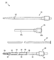
図1aおよび1bに、従来技術によるコープループロッキングカテーテル2を示す。カテーテル2は、中をドレナージ液が流れるチューブ4を含む。チューブ4の遠位端は、除去する液体をカテーテル内に入れるためのドレナージ開口部3を複数有する。チューブ4は、ポリウレタンなど好適な可撓性のポリマー材料でつくられる。チューブ4の近位端は、ハブ6などのコネクタ部品に取り付けられる。引き糸8は、チューブ4の近位端開口部9でカテーテル管腔10の内部からチューブ4に固定され、そこから伸びる。引き糸の第一の部位8aはチューブ4の遠位端領域まで伸び、第一の貫通点12でチューブの壁面を貫通する。引き糸の第二の部位8bはチューブ4の外側に沿って第二の貫通点14まで戻り、そこで再びチューブ4の管腔10に入る。引き糸の第三の部位8cは、第二の貫通点から戻ってハブ6を通り、チューブ4の最近位端から外に出る。
Detailed Description Figures 1a and 1b show a prior art co-loop locking catheter 2. The catheter 2 includes a tube 4 through which drainage fluid flows. The distal end of the tube 4 has a plurality of
本明細書において、「遠位(distal)」という用語はカテーテルの身体挿入部位から遠いことを意味し、「近位(proximal)」という用語はカテーテルの身体挿入部位に近いことを意味する。例えば、カテーテルの遠位端とは体内に配置することを意図した側のカテーテル先端を意味し、カテーテルの近位端とは挿入箇所もしくはその付近または体外に配置することを意図した側のカテーテル先端を意味する。本明細書において、「遠位領域(distal region)」という用語はカテーテル挿入部位から遠い体内の場所に配置することを意図した領域を意味し、「近位領域(proximal region)」という用語は挿入部位の近くに位置する領域を意味する。さらに、本明細書において、細長部品または糸の近位端および遠位端とは、それぞれ近位側および遠位側に配置されるよう適合された糸の部分を意味する。すなわち、糸の遠位端は糸の本当の端であってもよく、または遠位に配置されるよう適合された部分(例えば糸の中央領域)であってもよい。 As used herein, the term “distal” means distant from the catheter body insertion site, and the term “proximal” means close to the catheter body insertion site. For example, the distal end of the catheter means the catheter tip on the side intended to be placed inside the body, and the proximal end of the catheter means the catheter tip on the side intended to be placed at or near the insertion site or outside the body. Means. As used herein, the term “distal region” refers to a region intended for placement in a body location remote from the catheter insertion site, and the term “proximal region” refers to insertion It means the area located near the part. Further, as used herein, the proximal and distal ends of an elongate piece or yarn refer to portions of the yarn that are adapted to be disposed proximally and distally, respectively. That is, the distal end of the yarn may be the true end of the yarn, or may be a portion adapted to be placed distally (eg, the central region of the yarn).
コネクタ6から伸びる糸8の部分を引くと、第一の貫通点12が第二の貫通点14の方向に引っ張られる。糸8を引き続けると、カテーテル2の遠位端がループ(すなわち「ピッグテール」)を形成する(図1b)。この配置において、糸の部分8bの長さは事実上ゼロまで短くなる。カテーテルを挿入した体腔内でループが正しく形成されると、カテーテルが引き抜かれることを防止するための信頼性の高い手段が得られる。
When the portion of the thread 8 extending from the connector 6 is pulled, the
コープループロッキングカテーテル2を配置する手順においては、腎臓の穿通、その切開創の拡張、そして拡張した組織路へのカテーテル2の挿入が行われる。したがって、カテーテルは拡張した組織路内で腎組織と直接接触する状態でされる。 In the procedure of placing the co-loop locking catheter 2, the kidney is penetrated, the incision is expanded, and the catheter 2 is inserted into the expanded tissue tract. Thus, the catheter is placed in direct contact with renal tissue within the expanded tissue tract.
前述のように、この従来のカテーテル2による欠点の1つは、完全なループを作れるだけ十分にドレナージ対象の空隙内にカテーテル2を挿入しなければならないため、ループの形成が困難な場合があることである。カテーテル2を十分挿入しようとする際に、空隙内の種々の不規則部分(空隙が腎盂の場合は腎杯または尿管など)にカテーテル2が引っかかる可能性がある。不規則部分にカテーテル2が引っかかると、十分な空間が得られず、例えば糸8を引いても遠位端が巻き戻ることができないなどの状態が生じるため、ループの形成が困難になる。 As mentioned above, one of the disadvantages of this conventional catheter 2 is that it may be difficult to form a loop because the catheter 2 must be inserted into the drainage space enough to create a complete loop. That is. When the catheter 2 is to be fully inserted, the catheter 2 may get caught in various irregular portions in the space (such as the kidney cup or ureter when the space is a renal pelvis). When the catheter 2 is caught on the irregular portion, a sufficient space cannot be obtained, and for example, a state in which the distal end cannot be rewound even if the thread 8 is pulled occurs, so that it is difficult to form a loop.
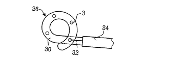
図2aにおいて、医療用装置セット20は、拡張器22、導入器24、ピッグテール(またはコープループタイプ)カテーテル26、およびガイドピンまたは心軸27を含む。導入器24は、スリーブ25aおよびハブ25bなどのコネクタ部品を含む。詳しく後述するように、拡張器22はドレナージ対象の空隙内に本発明の装置を配置するために使用する。カテーテル26は、導入器24のハブ25bと相互作用するよう構成される引っ張り手段28(例えば、リング部品、ストップ部品、またはストップ装置)を有する。ストップ装置28は、カテーテル管腔30に滑動可能な状態で取り付けられるリングまたはリング部品の形態であってもよい。リング28から、細長部品または引き糸32は、カテーテル26の遠位端(または遠位端付近)の遠位取り付け部34まで伸び、そこでカテーテル管腔30を貫通して例えば反対側に出、そこから戻ってリング28に接続する。引き糸32は、例えばチューブを貫通するための針を用いるか、またはカテーテルに穴をあけそこに糸を通すなどの手段により、チューブ先端に単純に糸を通すことによってカテーテルチューブ30を貫通する。引き糸は、ループが確実に形成されるよう、一般的に非弾性の糸である。引き糸32はカテーテルチューブ30に設けられた一対の開口部を通ることによってチューブに連結されるが、金属バンド、接着剤、または結び目などその他の適切な手段でカテーテルに連結されてもよい。
In FIG. 2 a, the medical device set 20 includes a
拡張器22は放射線不透過性部分23を含む。この機能を提供するには放射線不透過性をもたらす任意の方法および/または材料が使用可能であるが、例えばこの部分はプラチナ(Pt)または金(Au)など所望の放射線不透過性を有する金属でつくられていてもよい。放射線不透過性部分23の拡張器22上の位置は、拡張器22を導入器24の中に配置したときに放射線不透過性部分23がスリーブ25aの遠位端とちょうど同じ位置になるように選択する。詳しく後述するように、放射線不透過性部分23があることにより、医師は導入器24が集合管系内に配置されていることを蛍光透視で確認できる。
The
蛍光透視は体腔内の導入器を可視化する1つの方法であるが、体腔内の医療用装置(すなわち、導入器、針、ガイドワイヤ、拡張器、カテーテル)の配置を可視化するには超音波技術を用いてもよい。体腔内のこれら装置を可視化するための超音波技術は当業者に周知である。 Fluoroscopy is one way to visualize an introducer in a body cavity, but ultrasound techniques are used to visualize the placement of medical devices (ie, introducers, needles, guidewires, dilators, and catheters) within the body cavity. May be used. Ultrasound techniques for visualizing these devices in body cavities are well known to those skilled in the art.
カテーテル26、導入器24、拡張器22は、一般的な医療用等級のプラスチックから標準的な技術により作製される。例えば、プラスチックはポリウレタン、ポリプロピレン、ポリエチレン、ナイロン、ポリエチレンテレフタラート、ポリエテン、Hd-ポリエテン、ラテックス、およびその他の適切なポリマー、ならびにPebax(登録商標)のうち1つまたは複数であってよい。さらに、カテーテル26は2つ以上の材料で作製してもよい。剛性の異なる材料を使用して、領域ごとに剛性の異なるカテーテル26を作製してもよい。好ましくは、カテーテル26の一部を構成しループを形成するよう適合されたカテーテル26の遠位領域は、カテーテル26の一部を構成しループ形成時に導入器24内に配置されるよう適合されたカテーテル26の近位領域と比較して、大きい剛性を有する。剛性の異なる材料同士は溶接してもよく、または溶解により結合してもよい。または、カテーテル26の射出形成中に材料の剛性を制御できるような工程を用いてもよい。所望される場合は、部位ごとに厚さの異なるカテーテル26を作製してもよい。形状記憶合金またはばね金属もカテーテル26に使用してよい。
The
ガイドピンまたは心軸27は医療用等級の任意の金属またはポリマーで作製してよい。金属は、例えばステンレス鋼、ニチノール、またはチタンであってもよい。ポリマーは前述のポリマーのうち1つまたは複数のポリマーであってもよい。引き糸32はたとえばナイロンでつくられていてもよい。
The guide pin or
図2bおよび2cにおいて、カテーテル26は、糸32がチューブ30を貫通する場所に基づいて、チューブ30の長さに沿った任意の場所でループを形成するよう構成してよい。例えば図2bはカテーテル26の遠位端の位置で糸32がチューブ30を貫通する様子を示している。図2cは、カテーテル26の遠位端より所定の距離だけ近位側の位置で糸32がチューブ30を貫通する様子を示している。このようにすると、ループが形成された際、糸がカテーテル26を貫通する位置の所定の距離の分だけチューブ30がループより先に残る。
In FIGS. 2 b and 2 c, the
医療用装置セット20は、体腔をドレナージするためカテーテル26を体腔内に配置するために使用される。例えば図3a〜hにおいて、カテーテル26は腎盂をドレナージする目的で腎盂内に配置してもよい。まず、中空針37を用いて腎臓38を経皮的に穿刺し、集合管系39へのアクセス経路を確保する。この穿刺は腎杯39に針が刺入されるように行う(図3a)。次にガイドワイヤ42を中空針37の内腔に通して集合管系まで送達させる。これは針37の先端から約4〜5 cmの距離に相当する(図3b)。ガイドワイヤ42を体腔内に配置したら針を抜く(図3c)。次に、拡張器22を導入器24に挿入し、この拡張器と導入器のアセンブリをガイドワイヤ42に通して腎組織内に挿入する(図3d)。組織にアセンブリを通すことにより、最初に針37でつくったチャネルが広がるまたは拡張される。組織の拡張を可能な限り非侵襲的に行うため、導入器のスリーブ25aと、導入器のスリーブから出る拡張器22の突出部との境界は滑らかでなければならない。例えば、導入器のスリーブ25aの遠位端は、内径と拡張器22の外径との差がごくわずかとなるよう、テーパをつけてもよい。これを最も簡単に実現するには、スリーブ25aの遠位端の角度が例えば45°未満、好ましくは30°未満、最も好ましくは20°未満となるよう、非常に小さな角度でテーパをつける。一般的に角度が小さいほど好ましく、角度値の制約となるのは製造技術のみである。無論、スリーブ25aが十分薄い材料でできている場合は、拡張器22がスリーブ25aの中に非常によく合うのであれば必ずしもテーパは必要でない。導入器24と拡張器22との摩擦を低減するため、拡張器22にハイドロフィル(hydrofil)摩擦コーティングを施してもよい。拡張器22は拡張器22の近位端にあるハブを介して導入器24のハブ25bに接続してもよい。さらに、拡張器22の遠位端は好ましくは鋭利な先端として形成され、且つ、拡張器22の内径はガイドワイヤの直径と一致する。
The medical device set 20 is used to place a
次に、拡張器22と導入器24とのアセンブリを集合管系へとわずかに進める。このとき医師は、蛍光透視、超音波、またはX線によって、放射線不透過性部分23が集合管系内に位置していることを選択的に確認してもよい(図3e)。拡張器22は、放射線不透過性部分23がスリーブ25aの遠位端と一致するように導入器24内に配置されているため、医師は蛍光透視下に放射線不透過性部分を探すことによりスリーブ25aが集合管系にいつ入ったかを確認できる。次に拡張器22を引き抜くと、導入器が集合管系内に残る(図3f)。
Next, the assembly of
次にカテーテル26を導入器24に導入する(図3g)。導入器へのカテーテルの導入を容易にするため、まず剛性のガイドピン27をカテーテルに挿入することにより長軸方向の剛性を与えてカテーテルを支持する。カテーテル26はその可撓性のため導入器24内で引っかかる可能性があるが、こうすることによりその可能性が軽減される。
Next, the
導入器24とカテーテル26との摩擦を低減するため、カテーテルチューブ30に摩擦低減コーティングを施してもよい。さらに、接続を漏れのないものにするため、好ましくはハブ36とハブ25bとの間にOリングを配置する。
To reduce friction between
一般的に、導入器24および導入器とカテーテルとを組み立てたサブシステムは、滑らかで且つつぶれることなく容易に曲がる必要がある。
In general, the
図3gに示すようにリング28が導入器24のハブ25bと接するまでカテーテル26を導入器24に挿入すると、糸32が張るかまたはわずかに引っ張られる。糸32が引っ張られるのは、リング28がハブ25bに接する位置から、スリーブ25aからわずかに出るカテーテル遠位端34の糸取り付け位置まで、糸の長さが導入器の長さとほぼ等しいためである。糸32は引っ張られ、且つ弾性がないため伸長できず、そして遠位端の糸取り付け部34は導入器の遠位端からそれ以上離れられないことから、カテーテルをさらに導入器内へと進めるとチューブ30にループが形成される。ループ形成中は、ループとの干渉を防ぐためガイドピン27を取り外す。または、ガイドピン27を取り外さずに残してもよいが、カテーテル26と一緒にそれ以上進めることはしない。
When the
カテーテル26を導入器24内へさらに進めることによって、糸取り付け位置34より後ろのカテーテルチューブ30が導入器から押し出されて、取り付け位置34を越えて伸び、これによりループが形成され始める(図3h)。医師は、カテーテルのハブ36が導入器の対応するハブ25bと結合するまでカテーテル26を進める。このとき、ハブ36および25bは、例えばねじのかみ合い、差込みタイプのロック、またはその他任意の適したロック手段により連結させてもよい。こうすることにより、カテーテルがループにより腎臓内に効果的に係留された状態で、カテーテルが集合管系(すなわち腎盂)内に固定される。カテーテル26の配置手順をまとめると次のようになる:(1)針を用いてドレナージ対象の体腔まで組織にチャネルを設ける;(2)針にガイドワイヤを挿入し、ガイドワイヤを体腔内へと進める;(3)針を抜き、拡張器および導入器をガイドワイヤに通して組織を拡張する;(4)拡張器を除去し、遠位端に引き糸を取り付けたカテーテルをガイドワイヤに通してカテーテルに挿入する;(5)糸取り付け部が遠位側のカテーテル用開口部をわずかに超えたところでカテーテルの挿入を止める;(6)糸が引っ張られていること、および引っ張られた位置で固定されていることを確認する;(7)カテーテルをさらに導入器内へと進めることにより遠位側のカテーテル用開口部でループの形成を開始する;(8)ループが所望の大きさに形成されたらカテーテルと導入器とを連結する;および選択的に、(9)導入器/カテーテルアセンブリを患者の皮膚に固定する。
By further advancing the
一般的に、段階(5)および(6)は、導入器のハブ25bと接したときにストップ手段として機能するリング28に取り付けられた引き糸32によって自動的に行われる。所望のサイズのループも、カテーテルのハブ36が導入器のハブ25bと接したとき、またはこれら2つのハブを例えばねじまたは差込みタイプのロックなどにより適切に連結したときに所望のサイズのループが形成されるようカテーテルの長さを調節することによって、自動的に得られる。
In general, steps (5) and (6) are performed automatically by a pulling
より一般的には、カテーテル26の配置手順は次のように行ってもよい:(1)体腔周囲の組織を拡張してチャネルを形成する;(2)チャネルに導入器を配置する;(3)遠位端に引き糸を取り付けたカテーテルを導入器に挿入する;(4)糸取り付け部がカテーテル出口の開口部をわずかに超えたら、引き糸が引っ張られていること、および引っ張られた位置で固定されていることを確認する;(5)カテーテルをさらに導入器内へと進めることにより遠位側のカテーテル用開口部でループの形成を開始する;および、(6)ループが所望の大きさに形成されたらカテーテルをその位置に固定する。
More generally, the
図4a〜dに、ループ形成の鍵であるカテーテル26と導入器24との相互作用を示す。まず、リング28がコネクタ25bに接触するまでカテーテル26を導入器24の中に進める(図4a)。このときカテーテルの遠位端は導入器からわずかに突出し且つ糸を引っ張る。コネクタ25bからコネクタ36までの距離d1は形成されるループの外周にほぼ等しい。さらに、カテーテルを進めていく際、導入器から突出した部分のカテーテルの長さとコネクタ部品25b〜36間の距離との合計はほぼd1である。
4a-d show the interaction between
次に、カテーテル26をさらに少し導入器24内へと進める。リング28がコネクタ25bに当たっており且つ引き糸32がすでに張っていることから、カテーテル26をさらに進めるとループが形成され始める(図4b)。カテーテルを進めるにしたがって距離d1は距離d2へと短くなる。前述のように、距離d1の減少分は導入器から出た部分のカテーテルの長さとほぼ等しい。カテーテル26を導入器24内へとさらに進めても、引き糸32はほぼ一定の長さに保たれ、このためカテーテルの遠位端は導入器の遠位端付近に維持される。したがって、カテーテルチューブ30を導入器へと進めるにしたがってカテーテルチューブ30により大きなループが形成される(図4c)。距離d2が距離d3まで短くなると、それとほぼ同じ長さが導入器内へと進められる。
The
最後に、カテーテル26を導入器24内に完全に進めるとリング28がコネクタ部品25bと36とに挟まれ、距離d3がd4へと短くなる(図4d)。リング28がコネクタ部品25bと36とに挟まれたときのループの円周はd1にほぼ等しい。ループの円周は引き糸32の長さを増減させることにより設定できる。例えば、ループの円周を長くするには引き糸の長さを短くし、ループの円周を短くするには引き糸の長さを長くする。
Finally, completely advancing the
一般的に、導入器24の長さは、引っ張り手段もしくはリング部品に対する細長部品または引き糸32の取り付け部から細長部品と管状部の遠位領域との連結部までにわたる細長部品の長さとほぼ同じである。より具体的には、引っ張り手段もしくはリング部品に対する細長部品または引き糸32の取り付け部から細長部品と管状部の遠位領域との連結部までにわたる細長部品の長さは、導入器の長さより約3〜10 mm長い。
In general, the length of the
本明細書に説明する医療用装置20の利点の1つは、例えばカテーテルが詰まった場合などにカテーテル26の交換が容易なことである。事実、カテーテル26は、麻酔などの補助的な手段または装置の必要なしに看護師により交換可能である。具体的にはカテーテル26の交換は次のように行われる。まず、看護師または医師は、単純に導入器24とカテーテル26とのロックを解除し、カテーテルを導入器から引き抜く。カテーテル26を引き抜くことによりループのサイズは自動的に小さくなってゆく。カテーテル26が導入器から突出しなくなるところまで引き抜くとループが完全に消失する。引き糸32は導入器内壁とカテーテル外壁との間の空間でカテーテル26の外面に沿って通るため、糸がカテーテルまたは導入器に固定されるほど塩が晶出する可能性は低い。従来技術のカテーテルでは糸のほぼ全部がカテーテル内部を通るため、塩の晶出によるカテーテルへの糸の固定は最も多くみられる問題となっている。
One advantage of the
カテーテル26を取り出したら、新しいカテーテル26を用意し、カテーテルを押すことができるだけの十分な剛性を与えるためガイドピン27をカテーテル管腔に挿入し、カテーテルを再挿入する。次に、ガイドピン27を取り除くかまたは引き戻し、カテーテルの遠位端でループが形成されはじめるようカテーテル26を導入器24内に進める。
Once the
医療用装置20は上述のようにして非常に良好に機能するが、非常に良好に機能する改変もまた可能である。例えば、糸32は必ずしもリング28に固定しなくてもよい。その代わりに、糸32は、カテーテルチューブ30の遠位端に取り付けられしかし近位端は固定されない1本の糸として提供してもよい。糸は、近位端をリングに固定する代わりに、例えばコネクタ部品25aおよび/または36に固定可能な状態にする。このような実施例においては、遠位側の糸の取り付け部が所望の位置すなわち遠位側のカテーテルチューブの出口開口部のすぐ向こう側に達したことを示すための何らかの指示マークを糸に設けるべきである。この識別は、チューブ30に対する遠位側の糸取り付け部がちょうど所望の位置に達したときにマークが導入器のハブまたはコネクタ部品25bの近位側の挿入用開口部に達するように、単純な色マークを糸またはチューブに設けることにより実現してもよい。このとき、医師または看護師は糸の自由端を任意の適切な手段により導入器のハブ25bに固定する。適切な手段は、例えばコネクタ上に提供された締め付けであってもよく、または糸の直径がスリットの幅より大きいことによる摩擦嵌め合いで糸を嵌合させられるような、コネクタに設けられた非常に狭いスリットに糸を挿入することであってもよい。他にも、糸をハブ25bに確実に固定できる手段である限り多数の固定手段が利用可能である。
Although the
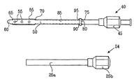
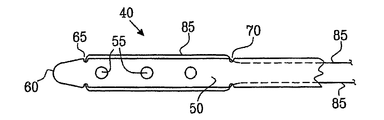
別の実施例である図5a〜cにおいて、導入器24とともに使用するよう構成されたドレナージカテーテル40はコネクタ45およびチューブ50を含む。チューブ50は、カテーテル40の遠位端60に液体ドレナージ用の開口部55を有する。チューブ50はまた、カテーテルの遠位端60に設けられた第一の開口部対65、第一の開口部対65より近位側に設けられた第二の開口部対70、および第二の開口部対70より近位側に設けられた第三の開口部対75を有する。ドレナージカテーテル40はまた、チューブ50に滑動可能な状態で取り付けられたストップ部品またはリング80を含む。
In another embodiment, FIGS. 5 a-c, a
ドレナージカテーテル40とドレナージカテーテル26との相違点の一つは、引き糸85がカテーテルの外側からカテーテルの内側へと通り、さらにまたカテーテルの外側へと戻ることである。具体的には、引き糸85は2つの端90、95を有し、この2つの端はいずれも例えば結び目、接着、またはその他の取り付け手段によりリング80に取り付けられる。引き糸85はリング80から第三の開口部対75へと伸び、そしてカテーテル40の内腔を通る。引き糸85は第二の開口部対70を通ってカテーテル管腔から外に出る。次に、引き糸85は第一の開口部対65に達するまでカテーテル40の外側に沿って伸び、第一の開口部対を通ってカテーテル管腔に入る。第一の開口部対65から第二の開口部対70までの距離は、カテーテル40を導入器24に挿入したときに形成されるループの円周にほぼ等しい。第三の開口部対75からコネクタ45までの距離は、第一の開口部対65から第二の開口部対70までの距離にほぼ等しい。引き糸85を第二の開口部対70に通すことにより、カテーテル40および導入器24を体腔内に配置した際に引き糸が導入器の遠位端をこすることが回避される。これにより糸の寿命が延び、且つ、カテーテル交換の理由となるその種の失敗が少なく抑えられるため、このことは利点である。
One difference between the
図5dにおいて、使用中、カテーテル40は、すでに体腔内に配置された導入器24内に、コネクタ25bがリング80と接触しこれにより引き糸85がぴんと張るまで進められる。カテーテル40を導入器24内にさらに進めることによって、コネクタ25bがリング80をカテーテルチューブ50に沿ってコネクタ45の方向に押す。
In FIG. 5d, in use, the
図5eにおいて、コネクタ25b、リング80、およびコネクタ45が互いに押し付けられるまでカテーテル40を導入器24内へと完全に進めると、カテーテル40の遠位端60でループ97が形成される。第二の開口部対70は、カテーテル40を導入器24内に完全に進めたときに導入器の遠位端が開口部対70より近位側となるよう、カテーテルチューブ50の長さに沿って遠位端からある距離の位置に配置される。こうすることにより、カテーテル40および導入器24が体腔内に長時間されても、引き糸85が導入器24の遠位端でこすれる可能性が小さくなる。引き糸85が導入器24の遠位端で継続的または定期的にこすられると引き糸が損傷し切れる可能性がある。
In FIG. 5e, when the
図5aでは第二の開口部対70から第三の開口部対75までの距離が特定の長さになっているが、この距離は増減させてもよい。例えば、第三の開口部対を遠位端60に近づけることによりこの距離を約1 cmとし、引き糸がカテーテル40の内腔を通る距離がこの1 cmだけとなるようにしてもよい。上述のように、引き糸に塩が沈着するとカテーテル内腔に対して引き糸が固定されるが、この距離を短くすることにより塩の沈着を起こし得る引き糸の長さを短くできるという利点がある。引き糸のうち1 cmが内腔に固定されたとしても、医師はこの固定を容易に解いてカテーテルのループを解消できる可能性が高く、したがって医師はカテーテルを導入器から容易に引き抜くことができる。
In FIG. 5a, the distance from the
別の実施例である図6aおよび6bにおいて、2つの体腔をドレナージできるドレナージカテーテル100は、導入器24とともに使用するよう構成され、且つコネクタ105およびチューブ110を含む。チューブ110は、第一の体腔から液体をドレナージするための第一の開口部対115を遠位端120に有し、且つ、第二の体腔から液体をドレナージするための第二の開口部対125を中央部130に有する。第一の開口部対115は第一のループ135に形成され、第二の開口部対125は第二のループ140に形成される。第一のループ135をチューブ110に形成するには、例えば弯曲した心軸上にカテーテル100を配置しこのアセンブリをヒートオーブンに入れて心軸の弯曲をカテーテルに伝えるなどの標準的な方法を用いる。カテーテル100はまた、リング145、引き糸150、および引き糸が通る開口部155を有する。カテーテル100を導入器24内に進めることによって、リング145がチューブ110に沿って滑動しループ140が形成される。カテーテル100はまた、カテーテル100の配置を蛍光透視下で観察し第一のループが第一のドレナージ対象の体腔内に正しく配置されていることを確認できるよう、第一のループ135に取り付けられた放射線不透過性バンド160を有していてもよい。
In another example, FIGS. 6 a and 6 b, a
カテーテル100は、例えば腎臓および膀胱のドレナージに使用される。カテーテル100は上述のドレナージカテーテルと同様の方法で挿入される。ただし最初に、導入器24に通すため第一のループ135をまっすぐにする。選択的に、カテーテル100をガイドワイヤに通してもよい。いずれの場合においても、第一のループ135が膀胱に入るまでカテーテル100を進める。このとき、導入器のコネクタ25bがリング145を押し、第二のループ140が腎臓内で形成される。
The
また別の態様においては、引き糸をカテーテルの遠位端付近に固定する必要はない。例えば尿管付近など腎臓のより奥の位置で腎臓(集合管系)をドレナージすることが望ましい場合は、集合管系への進入位置より最大約10 cm向こうまで到達できる比較的長い先端を提供する必要がある。しかし、信頼できる固定を得るためには、集合管系への侵入位置にループを配置するのが有利である。カテーテル上の糸の固定位置は、導入器のチューブの遠位側開口部を越えたすぐの位置に配置される。 In another aspect, the pull string need not be secured near the distal end of the catheter. If it is desirable to drain the kidney (collecting duct system) deeper than the kidney, for example near the ureter, provide a relatively long tip that can reach up to about 10 cm beyond the entry position into the collecting duct system There is a need. However, in order to obtain a reliable fixation, it is advantageous to place a loop at the entry point into the collecting pipe system. The fixed position of the thread on the catheter is positioned just beyond the distal opening of the introducer tube.
以上、ロックループカテーテルの複数の態様を説明した。しかし、本発明の精神および範囲から逸脱することなく種々の改変を行い得ることが理解されるものと思われる。例えば、図7において、チューブ30の両側に沿ってわたされる糸32は、糸の片端を遠位端34に取り付け、他端をストップ部品またはリング28に取り付けることによって、チューブの片側だけに沿ってわたされるよう構成してもよい。ただしこの場合は、糸の端がチューブに確実に取り付けられるよう、例えば結び目、接着、金属バンド、成形などによる取り付け手段170を先端に設ける必要がある。金属バンドは、蛍光透視下で観察できるよう放射線不透過性の金属バンドであってもよい。引き糸は、図にはカテーテルの外側を通る様子が示されているが、図5aのドレナージカテーテル40に関する説明と同様、カテーテルの内側および外側の両方を通るように構成してもよい。同様に、腎盂のカテーテルという用途に関してカテーテルの説明を行ったが、本発明のカテーテルの用途は腎盂のみに限られないことが理解されるべきである。例えば、本発明のカテーテルはヒトまたは動物のその他の体腔のドレナージにも同様に良好に機能すると考えられ、体腔の例としては膀胱、胆嚢、膿瘍、腹腔、胸腔などがあるがこれらに限定されることはない。したがって、他の態様も添付の特許請求の範囲に入る。
In the above, the several aspect of the lock loop catheter was demonstrated. However, it will be understood that various modifications may be made without departing from the spirit and scope of the invention. For example, in FIG. 7, the
(図1a)従来のコープループカテーテルの側面図である。
(図1b)図1aのカテーテルの遠位端の拡大側面図であり、カテーテルの遠位端に形成されたループを示す。
(図2a)拡張器、導入器、心軸、およびカテーテルを有する、体腔のドレナージ用に使用される医療用装置セットの側面図である。
(図2b)図2aのカテーテルの遠位端の拡大側面図であり、糸がカテーテルの遠位端までわたされているときにカテーテルの遠位端に形成されたループを示す。
(図2c)図2aのカテーテルの遠位端の拡大側面図であり、糸がカテーテルの中央領域までわたされているときにカテーテルの遠位端に形成されたループを示す。
(図3a〜h)図2aのカテーテルを腎盂内に配置するために図2aの医療用装置セットを使用する手順を示した図である。
(図4a〜d)リングと導入器のハブとの相互作用によるループ形成を示した図である。
(図5a)体腔ドレナージ用のドレナージカテーテルおよび導入器の第二の態様を示した側面図である。
(図5b)図5aのカテーテルの遠位端の拡大側面図である。
(図5c)図5aのカテーテルの中央部の拡大側面図であり、滑動可能なリングおよび取り付けられた引き糸を示す。
(図5d)導入器に挿入された図5aのドレナージカテーテルを示した側面図である。
(図5e)ループが形成されるよう導入器にさらに挿入された図5aのドレナージカテーテルを示した側面図である。
(図6a)2つの体腔をドレナージするためのドレナージカテーテルであり、遠位端にループが形成され且つ糸がカテーテルの中央部までわたされているカテーテルを示した側面図である。
(図6b)カテーテルの中央部でループが形成されるよう導入器に挿入された図6aのドレナージカテーテルを示した側面図である。
(図7)引き糸を1本有するドレナージカテーテルを示した側面図である。
FIG. 1a is a side view of a conventional co-op loop catheter.
FIG. 1b is an enlarged side view of the distal end of the catheter of FIG. 1a showing a loop formed at the distal end of the catheter.
FIG. 2a is a side view of a medical device set used for body cavity drainage with a dilator, introducer, mandrel, and catheter.
FIG. 2b is an enlarged side view of the distal end of the catheter of FIG. 2a showing a loop formed at the distal end of the catheter as the thread is passed to the distal end of the catheter.
FIG. 2c is an enlarged side view of the distal end of the catheter of FIG. 2a showing the loop formed at the distal end of the catheter when the thread is passed to the central region of the catheter.
FIGS. 3a-h show procedures for using the medical device set of FIG. 2a to place the catheter of FIG. 2a in the renal pelvis.
(FIGS. 4a-d) FIGS. 4A-4D show loop formation due to the interaction between the ring and the hub of the introducer.
(FIG. 5a) It is the side view which showed the 2nd aspect of the drainage catheter and introducer for body cavity drainage.
FIG. 5b is an enlarged side view of the distal end of the catheter of FIG. 5a.
FIG. 5c is an enlarged side view of the central portion of the catheter of FIG. 5a showing a slidable ring and attached pull string.
FIG. 5d is a side view of the drainage catheter of FIG. 5a inserted into the introducer.
FIG. 5e is a side view of the drainage catheter of FIG. 5a further inserted into the introducer to form a loop.
FIG. 6a is a side view of a drainage catheter for draining two body cavities, with a loop formed at the distal end and a thread passed to the middle of the catheter.
FIG. 6b is a side view of the drainage catheter of FIG. 6a inserted into the introducer such that a loop is formed at the center of the catheter.
FIG. 7 is a side view showing a drainage catheter having one pull thread.
Claims (55)
遠位領域および近位領域を有する管状部;
管状部の外周の少なくとも一部を取り囲むリング部品;
管状部に沿って滑動可能なリング部品;
リング部品に取り付けられる近位端、および管状部の遠位領域に連結される遠位端を有する少なくとも1つの細長部品;ならびに
カテーテルを導入器の中に進めることにより前記カテーテルの遠位側でループが形成された時であって、かつ前記カテーテルをその位置に固定する際に、前記ループを固定するために用いるコネクタ部品であって、管状部の近位領域に取り付けられた前記コネクタ部品。Catheter including:
A tubular portion having a distal region and a proximal region;
A ring part surrounding at least a part of the outer periphery of the tubular part;
Ring parts slidable along the tubular part;
At least one elongate part having a proximal end attached to the ring part and a distal end connected to the distal region of the tubular part; and a loop on the distal side of the catheter by advancing the catheter into the introducer A connector component used to secure the loop when the catheter is formed and when the catheter is secured in position, wherein the connector component is attached to the proximal region of the tubular section.
管状部が、外表面と内腔との間にわたり、且つ、第一の開口部対より近位側に配置された第二の開口部対を含み、且つ
細長部品が、外表面に沿って第一の開口部対と第二の開口部対との間にわたり、且つ、内腔の少なくとも一部に沿って第二の開口部対とリング部品との間にわたる、カテーテル。The catheter according to claim 2,
The tubular portion includes a second pair of openings disposed between the outer surface and the lumen and proximal to the first pair of openings, and the elongate component extends along the outer surface. A catheter spanning between one opening pair and a second opening pair and spanning between the second opening pair and the ring component along at least a portion of the lumen.
管状部が、外表面と内腔との間にわたり、且つ、第二の開口部対より近位側に配置された第三の開口部対を含み、且つ
細長部品が、外表面に沿って、第三の開口部対とリング部品との間にわたるカテーテル。The catheter according to claim 4,
The tubular portion includes a third pair of openings disposed between the outer surface and the lumen and proximal to the second pair of openings, and the elongated portion is along the outer surface; A catheter spanning between the third pair of openings and the ring piece.
近位端と遠位端との間にわたる長軸方向のチャネルを有するシースと、長軸方向のチャネルを有しシースの近位端に接続されるコネクタ部品とを有する導入器;
を含むカテーテル留置キットであって、
カテーテルが導入器内に十分な形で配置されたとき、リング部品が導入器の近位端に隣接し、これにより細長部品が引っ張られ、且つ、カテーテルが導入器内に収容される際、カテーテルのコネクタ部品を導入器のコネクタ部品に取り外し可能な状態で取り付けることができる、カテーテル留置キット。A catheter comprising a connector part, a tubular part, at least one elongated part, and a ring part, the tubular part having a distal region and a proximal region, the connector part being attached to the proximal region of the tubular part, A catheter having a proximal end where the part is attached to the ring part and a distal end connected to the distal region of the tubular part, the ring part being able to slide along the tubular part; An introducer having a sheath having a longitudinal channel extending between the distal ends and a connector component having a longitudinal channel and connected to the proximal end of the sheath;
A catheter indwelling kit comprising:
When the catheter is fully positioned within the introducer, the ring component is adjacent to the proximal end of the introducer, thereby pulling the elongate component, and when the catheter is received within the introducer, the catheter The catheter indwelling kit can be removably attached to the connector part of the introducer.
管状部が、外表面と内腔との間にわたり且つ第一の開口部対より近位側に配置された第二の開口部対を含み、且つ
細長部品が、外表面に沿って第一の開口部対と第二の開口部対との間にわたり、且つ、内腔の少なくとも一部に沿って第二の開口部対とリング部品との間にわたる、カテーテル留置キット。The catheter indwelling kit according to claim 11,
The tubular portion includes a second pair of openings disposed between the outer surface and the lumen and proximal to the first pair of openings, and the elongate component includes a first portion along the outer surface. A catheter placement kit spanning between an opening pair and a second opening pair and between the second opening pair and the ring component along at least a portion of the lumen.
管状部が、外表面と内腔との間にわたり且つ第二の開口部対より近位側に配置された第三の開口部対を含み、且つ
細長部品が、外表面に沿って、第三の開口部対とリング部品との間にわたる、カテーテル留置キット。The catheter indwelling kit according to claim 13,
The tubular portion includes a third opening pair disposed between the outer surface and the lumen and proximal to the second opening pair, and the elongated component extends along the outer surface; A catheter indwelling kit that spans between a pair of openings and a ring component.
ハブとシースとを含む導入器であって、シースが近位端と遠位端との間にわたる長軸方向のチャネルを有し、ハブが長軸方向のチャネルを有し且つシースの近位端に接続され、且つ、接続されたハブおよびシースが長さを有する導入器
を含むカテーテル留置キットであって、
細長部品の長さがハブおよびシースの長さより3〜10 mm長く、且つ、カテーテルが導入器内に十分な形で配置されたとき、ストップ部品が導入器の近位端に隣接し、これにより細長部品が引っ張られる、カテーテル留置キット。A catheter that includes a tubular portion, at least one elongate component, and a stop component, the tubular portion having a distal region, the elongate component having a length, a proximal end, and a distal end, A catheter having a distal end attached to the distal region of the tubular portion, a proximal end of the elongated piece attached to the stop piece, and the stop piece slidable along the tubular piece; and a hub and sheath Wherein the sheath has a longitudinal channel extending between the proximal and distal ends, the hub has a longitudinal channel and is connected to the proximal end of the sheath; And a catheter placement kit comprising an introducer having a length of connected hub and sheath,
When the length of the elongated part is 3-10 mm longer than the length of the hub and sheath, and the catheter is fully placed in the introducer, the stop piece is adjacent to the proximal end of the introducer, thereby A catheter indwelling kit in which the elongated part is pulled.
管状部が、外表面と内腔との間にわたり且つ第一の開口部対より近位側に配置された第二の開口部対を含み、且つ
細長部品が、外表面に沿って第一の開口部対と第二の開口部対との間にわたり、且つ、内腔の少なくとも一部に沿って第二の開口部対とストップ部品との間にわたる、カテーテル留置キット。The catheter indwelling kit according to claim 34,
The tubular portion includes a second pair of openings disposed between the outer surface and the lumen and proximal to the first pair of openings, and the elongate component includes a first portion along the outer surface. A catheter placement kit spanning between an opening pair and a second opening pair and between the second opening pair and the stop piece along at least a portion of the lumen.
管状部が、外表面と内腔との間にわたり且つ第二の開口部対より近位側に配置された第三の開口部対を含み、且つ
細長部品が、外表面に沿って第三の開口部対とストップ部品との間にわたる、カテーテル留置キット。The catheter placement kit according to claim 36,
The tubular portion includes a third pair of openings disposed between the outer surface and the lumen and proximal to the second pair of openings, and the elongated component extends along the outer surface to the third A catheter placement kit that spans between the opening pair and the stop piece.
Applications Claiming Priority (2)
| Application Number | Priority Date | Filing Date | Title |
|---|---|---|---|
| US39166702P | 2002-06-27 | 2002-06-27 | |
| PCT/SE2003/001128 WO2004002563A1 (en) | 2002-06-27 | 2003-06-27 | Drainage catheter |
Publications (3)
| Publication Number | Publication Date |
|---|---|
| JP2005530582A JP2005530582A (en) | 2005-10-13 |
| JP2005530582A5 JP2005530582A5 (en) | 2006-07-13 |
| JP4468807B2 true JP4468807B2 (en) | 2010-05-26 |
Family
ID=30000730
Family Applications (1)
| Application Number | Title | Priority Date | Filing Date |
|---|---|---|---|
| JP2004517456A Expired - Fee Related JP4468807B2 (en) | 2002-06-27 | 2003-06-27 | Drainage catheter |
Country Status (9)
| Country | Link |
|---|---|
| US (5) | US7481805B2 (en) |
| EP (1) | EP1534374B1 (en) |
| JP (1) | JP4468807B2 (en) |
| AT (1) | ATE350090T1 (en) |
| AU (1) | AU2003239098B2 (en) |
| BR (1) | BR0312218A (en) |
| CA (1) | CA2489586C (en) |
| DE (1) | DE60310949T2 (en) |
| WO (1) | WO2004002563A1 (en) |
Families Citing this family (54)
| Publication number | Priority date | Publication date | Assignee | Title |
|---|---|---|---|---|
| US8066674B2 (en) * | 2003-01-27 | 2011-11-29 | Heuser Richard R | Catheter introducer system |
| US7217256B2 (en) * | 2003-11-17 | 2007-05-15 | Angiodynamics, Inc. | Locking catheter hub |
| US7465286B2 (en) | 2004-03-03 | 2008-12-16 | C. R. Bard, Inc. | Loop-tip catheter |
| US7686825B2 (en) | 2004-03-25 | 2010-03-30 | Hauser David L | Vascular filter device |
| EP1850903A1 (en) * | 2005-02-09 | 2007-11-07 | Innoventus Project AB | Drainage catheter |
| US20060229573A1 (en) * | 2005-04-08 | 2006-10-12 | Mckinley Medical L.L.L.P. | Adjustable infusion catheter |
| US20070066881A1 (en) | 2005-09-13 | 2007-03-22 | Edwards Jerome R | Apparatus and method for image guided accuracy verification |
| EP1924198B1 (en) | 2005-09-13 | 2019-04-03 | Veran Medical Technologies, Inc. | Apparatus for image guided accuracy verification |
| US9387308B2 (en) | 2007-04-23 | 2016-07-12 | Cardioguidance Biomedical, Llc | Guidewire with adjustable stiffness |
| US20080281291A1 (en) * | 2007-05-07 | 2008-11-13 | Claude Tihon | Drainage/irrigation urethral catheter |
| US9079006B1 (en) | 2008-03-28 | 2015-07-14 | Uresil, Llc | Suture locking mechanism |
| US8177773B2 (en) * | 2008-03-28 | 2012-05-15 | Uresil, Llc | Locking medical catheter |
| US9399112B2 (en) | 2008-04-22 | 2016-07-26 | Becton, Dickinson And Company | Catheter hole having an inclined trailing edge |
| US8496629B2 (en) | 2008-04-22 | 2013-07-30 | Becton, Dickinson And Company | Catheter hole having a flow breaking feature |
| US8858528B2 (en) * | 2008-04-23 | 2014-10-14 | Ncontact Surgical, Inc. | Articulating cannula access device |
| US8267951B2 (en) | 2008-06-12 | 2012-09-18 | Ncontact Surgical, Inc. | Dissecting cannula and methods of use thereof |
| EP2293838B1 (en) | 2008-07-01 | 2012-08-08 | Endologix, Inc. | Catheter system |
| US9393382B2 (en) * | 2009-05-05 | 2016-07-19 | Robert W. Heck | High-flow tapered peripheral IV catheter with side outlets |
| US8480640B2 (en) * | 2009-05-22 | 2013-07-09 | Robert J. Santimaw | Noninvasive bodily waste collection system and methods of use |
| WO2011014201A1 (en) * | 2009-07-29 | 2011-02-03 | C. R. Bard, Inc. | Catheter having improved drainage and/or a retractable sleeve and method of using the same |
| WO2011049824A1 (en) * | 2009-10-22 | 2011-04-28 | Vance Products Incorporated, D/B/A Cook Urological Incorporated | Locking assembly for a drainage catheter |
| EP2504055B1 (en) * | 2009-11-24 | 2018-02-28 | Cook Medical Technologies LLC | Locking assembly for a drainage catheter |
| US20110190734A1 (en) * | 2010-02-03 | 2011-08-04 | Richard Graffam | Mechanical Advantage For Hub Linear Travel For A Drainage Catheter |
| US8808261B2 (en) * | 2010-12-15 | 2014-08-19 | Allyson Cortney Berent | Ureteral bypass devices and procedures |
| WO2012118901A1 (en) | 2011-03-01 | 2012-09-07 | Endologix, Inc. | Catheter system and methods of using same |
| WO2013059204A1 (en) * | 2011-10-21 | 2013-04-25 | Boston Scientific Scimed, Inc. | Locking catheter hub |
| US9138165B2 (en) | 2012-02-22 | 2015-09-22 | Veran Medical Technologies, Inc. | Systems, methods and devices for forming respiratory-gated point cloud for four dimensional soft tissue navigation |
| US10792067B2 (en) | 2013-06-03 | 2020-10-06 | Faculty Physicians And Surgeons Of Loma Linda University Of Medicine | Methods and apparatuses for fluoro-less or near fluoro-less percutaneous surgery access |
| CA2914359A1 (en) * | 2013-06-03 | 2014-12-11 | Faculty Physicians And Surgeons Of Loma Linda University School Of Medicine | Methods and apparatuses for fluoro-less or near fluoro-less percutaneous surgery access |
| KR101464523B1 (en) * | 2013-09-16 | 2014-11-24 | 유앤아이 주식회사 | Steerable catheter |
| WO2015061365A1 (en) | 2013-10-21 | 2015-04-30 | Inceptus Medical, Llc | Methods and apparatus for treating embolism |
| CN103800951B (en) * | 2014-01-23 | 2016-05-25 | 广州市凌捷医疗器械有限公司 | The generation method of drainage catheter and superslide coating thereof |
| US20150305650A1 (en) | 2014-04-23 | 2015-10-29 | Mark Hunter | Apparatuses and methods for endobronchial navigation to and confirmation of the location of a target tissue and percutaneous interception of the target tissue |
| US20150305612A1 (en) | 2014-04-23 | 2015-10-29 | Mark Hunter | Apparatuses and methods for registering a real-time image feed from an imaging device to a steerable catheter |
| US10456565B2 (en) * | 2015-01-13 | 2019-10-29 | Cook Medical Technologies Llc | Locking loop catheter |
| CN104826211B (en) * | 2015-04-09 | 2018-06-19 | 广州新诚生物科技有限公司 | Cross double-sleeve drainage tube |
| WO2017004265A1 (en) | 2015-06-30 | 2017-01-05 | Endologix, Inc. | Locking assembly for coupling guidewire to delivery system |
| EP3352834A4 (en) | 2015-09-22 | 2019-05-08 | Faculty Physicians and Surgeons of Loma Linda University School of Medicine | Kit and method for reduced radiation procedures |
| JP7253376B2 (en) | 2015-10-23 | 2023-04-06 | イナリ メディカル, インコーポレイテッド | Endovascular treatment of vascular occlusion and related devices, systems and methods |
| US10207085B2 (en) * | 2016-05-19 | 2019-02-19 | Timothy Murphy | Medical drainage catheter with break-away tip and extraluminal retention apparatus |
| US10610668B2 (en) | 2016-10-05 | 2020-04-07 | Becton, Dickinson And Company | Catheter with an asymmetric tip |
| CN116421266A (en) | 2016-10-24 | 2023-07-14 | 伊纳里医疗有限公司 | Devices and methods for treating vascular occlusion |
| KR20200010161A (en) | 2016-11-22 | 2020-01-30 | 시네코어 엘엘씨 | Visiblewire septal transit system for treatment of mitral valve |
| WO2019055154A2 (en) | 2017-08-06 | 2019-03-21 | Synecor Llc | Systems and methods for transseptal delivery of therapeutic devices of the heart |
| EP3678731A4 (en) | 2017-09-06 | 2021-06-09 | Inari Medical, Inc. | Hemostasis valves and methods of use |
| US11154314B2 (en) | 2018-01-26 | 2021-10-26 | Inari Medical, Inc. | Single insertion delivery system for treating embolism and associated systems and methods |
| WO2020036809A1 (en) | 2018-08-13 | 2020-02-20 | Inari Medical, Inc. | System for treating embolism and associated devices and methods |
| US11135421B2 (en) | 2019-02-07 | 2021-10-05 | Synecor Llc | Conduit for transseptal passage of devices to the aorta |
| US20200338324A1 (en) * | 2019-04-23 | 2020-10-29 | Merit Medical Systems, Inc. | Drainage catheter with suture lumen |
| US11141561B2 (en) | 2019-07-02 | 2021-10-12 | Delbert Kwan | Urinary catheter with guide wire |
| CN211884905U (en) | 2019-08-22 | 2020-11-10 | 贝克顿·迪金森公司 | Balloon dilatation catheter and balloon thereof |
| AU2020368528A1 (en) | 2019-10-16 | 2022-04-21 | Inari Medical, Inc. | Systems, devices, and methods for treating vascular occlusions |
| GB2611491A (en) | 2020-06-24 | 2023-04-05 | Winston Weisse Charles | Ureteral bypass devices and procedures |
| JP7054570B1 (en) | 2021-11-16 | 2022-04-14 | 義弘 岸上 | Painless catheter for organs communicated with an opening on the body surface |
Family Cites Families (14)
| Publication number | Priority date | Publication date | Assignee | Title |
|---|---|---|---|---|
| US4740195A (en) * | 1986-02-14 | 1988-04-26 | Medi-Tech, Incorporated | Drainage catheter |
| US4906230A (en) * | 1987-06-30 | 1990-03-06 | Baxter Travenol Laboratories, Inc. | Steerable catheter tip |
| US4960134A (en) * | 1988-11-18 | 1990-10-02 | Webster Wilton W Jr | Steerable catheter |
| US6033378A (en) * | 1990-02-02 | 2000-03-07 | Ep Technologies, Inc. | Catheter steering mechanism |
| ATE123957T1 (en) * | 1990-12-07 | 1995-07-15 | Ruesch Willy Ag | MEDICAL INSTRUMENT WITH DIRECTORABLE TIP. |
| EP0619748B1 (en) * | 1991-08-28 | 1995-11-08 | Medtronic, Inc. | Steerable stylet and manipulative handle assembly |
| EP0609020B1 (en) * | 1993-01-28 | 1998-03-18 | Cook Incorporated | Retention means for catheter |
| US5352198A (en) * | 1993-11-24 | 1994-10-04 | Uresil Corporation | Locking catheter system |
| US6546280B2 (en) * | 1996-06-18 | 2003-04-08 | Cook Incorporated | Indwelling catheter |
| US5928208A (en) * | 1997-08-29 | 1999-07-27 | Boston Scientific Corporation | Retention mechanism for catheter with distal anchor |
| US5941849A (en) | 1997-08-29 | 1999-08-24 | Scimed Life Systems, Inc. | Suture retention device |
| US20010044625A1 (en) * | 1998-05-27 | 2001-11-22 | Cary Hata | Catheter for circular tissue ablation and methods thereof |
| US6217528B1 (en) * | 1999-02-11 | 2001-04-17 | Scimed Life Systems, Inc. | Loop structure having improved tissue contact capability |
| JP2004013744A (en) * | 2002-06-10 | 2004-01-15 | Takeshi Sakamura | Issuing system for digital content and issuing method |
-
2003
- 2003-06-26 US US10/606,538 patent/US7481805B2/en not_active Expired - Fee Related
- 2003-06-27 AU AU2003239098A patent/AU2003239098B2/en not_active Ceased
- 2003-06-27 BR BR0312218-2A patent/BR0312218A/en not_active Application Discontinuation
- 2003-06-27 DE DE60310949T patent/DE60310949T2/en not_active Expired - Lifetime
- 2003-06-27 WO PCT/SE2003/001128 patent/WO2004002563A1/en active IP Right Grant
- 2003-06-27 EP EP03733813A patent/EP1534374B1/en not_active Expired - Lifetime
- 2003-06-27 CA CA2489586A patent/CA2489586C/en not_active Expired - Fee Related
- 2003-06-27 AT AT03733813T patent/ATE350090T1/en not_active IP Right Cessation
- 2003-06-27 JP JP2004517456A patent/JP4468807B2/en not_active Expired - Fee Related
-
2006
- 2006-10-31 US US11/590,884 patent/US20070060914A1/en not_active Abandoned
- 2006-10-31 US US11/590,501 patent/US20070100299A1/en not_active Abandoned
- 2006-10-31 US US11/590,422 patent/US20070049905A1/en not_active Abandoned
- 2006-10-31 US US11/590,557 patent/US20070049906A1/en not_active Abandoned
Also Published As
| Publication number | Publication date |
|---|---|
| WO2004002563A1 (en) | 2004-01-08 |
| DE60310949D1 (en) | 2007-02-15 |
| US20040039339A1 (en) | 2004-02-26 |
| US20070060914A1 (en) | 2007-03-15 |
| JP2005530582A (en) | 2005-10-13 |
| EP1534374B1 (en) | 2007-01-03 |
| US7481805B2 (en) | 2009-01-27 |
| CA2489586A1 (en) | 2004-01-08 |
| AU2003239098A1 (en) | 2004-01-19 |
| BR0312218A (en) | 2005-04-12 |
| US20070049906A1 (en) | 2007-03-01 |
| AU2003239098B2 (en) | 2008-03-06 |
| US20070100299A1 (en) | 2007-05-03 |
| EP1534374A1 (en) | 2005-06-01 |
| US20070049905A1 (en) | 2007-03-01 |
| DE60310949T2 (en) | 2007-10-11 |
| ATE350090T1 (en) | 2007-01-15 |
| CA2489586C (en) | 2010-08-24 |
Similar Documents
| Publication | Publication Date | Title |
|---|---|---|
| JP4468807B2 (en) | Drainage catheter | |
| US9233226B2 (en) | Drainage catheter with pig-tail straightener | |
| US5308318A (en) | Easy-exchange drainage catheter system with integral obturator channel | |
| US8211087B2 (en) | Distal wire stop | |
| US8292872B2 (en) | Distal wire stop having adjustable handle | |
| US8206320B2 (en) | System and method for introducing multiple medical devices | |
| US8591563B2 (en) | Catheter with splittable wall shaft and peel tool | |
| AU776988B2 (en) | Single operator exchange biliary catheter with common distal lumen | |
| US20060200079A1 (en) | Drainage catheter | |
| US20150011834A1 (en) | System and method for introducing multiple medical devices | |
| JP2000300679A (en) | Catheter system | |
| JP2003525711A (en) | Quickly replaceable catheter with removable hood | |
| US8496644B2 (en) | Drainage catheter tip shape configuration | |
| US20110190734A1 (en) | Mechanical Advantage For Hub Linear Travel For A Drainage Catheter | |
| CN111372528A (en) | Obturator, sheath and method for using same | |
| US20050085746A1 (en) | Retractable sheath introducer | |
| CN111671984A (en) | Convertible nephroureteral catheter | |
| TWI322695B (en) | Drainage catheter | |
| EP1850903A1 (en) | Drainage catheter |
Legal Events
| Date | Code | Title | Description |
|---|---|---|---|
| A521 | Request for written amendment filed |
Free format text: JAPANESE INTERMEDIATE CODE: A523 Effective date: 20060526 |
|
| A621 | Written request for application examination |
Free format text: JAPANESE INTERMEDIATE CODE: A621 Effective date: 20060526 |
|
| RD04 | Notification of resignation of power of attorney |
Free format text: JAPANESE INTERMEDIATE CODE: A7424 Effective date: 20060526 |
|
| A131 | Notification of reasons for refusal |
Free format text: JAPANESE INTERMEDIATE CODE: A131 Effective date: 20090401 |
|
| A521 | Request for written amendment filed |
Free format text: JAPANESE INTERMEDIATE CODE: A523 Effective date: 20090615 |
|
| A521 | Request for written amendment filed |
Free format text: JAPANESE INTERMEDIATE CODE: A523 Effective date: 20090831 |
|
| A131 | Notification of reasons for refusal |
Free format text: JAPANESE INTERMEDIATE CODE: A131 Effective date: 20091007 |
|
| A521 | Request for written amendment filed |
Free format text: JAPANESE INTERMEDIATE CODE: A523 Effective date: 20091007 |
|
| A131 | Notification of reasons for refusal |
Free format text: JAPANESE INTERMEDIATE CODE: A131 Effective date: 20091026 |
|
| A521 | Request for written amendment filed |
Free format text: JAPANESE INTERMEDIATE CODE: A523 Effective date: 20100121 |
|
| TRDD | Decision of grant or rejection written | ||
| A01 | Written decision to grant a patent or to grant a registration (utility model) |
Free format text: JAPANESE INTERMEDIATE CODE: A01 Effective date: 20100208 |
|
| A01 | Written decision to grant a patent or to grant a registration (utility model) |
Free format text: JAPANESE INTERMEDIATE CODE: A01 |
|
| A61 | First payment of annual fees (during grant procedure) |
Free format text: JAPANESE INTERMEDIATE CODE: A61 Effective date: 20100225 |
|
| R150 | Certificate of patent or registration of utility model |
Free format text: JAPANESE INTERMEDIATE CODE: R150 |
|
| FPAY | Renewal fee payment (event date is renewal date of database) |
Free format text: PAYMENT UNTIL: 20130305 Year of fee payment: 3 |
|
| FPAY | Renewal fee payment (event date is renewal date of database) |
Free format text: PAYMENT UNTIL: 20130305 Year of fee payment: 3 |
|
| FPAY | Renewal fee payment (event date is renewal date of database) |
Free format text: PAYMENT UNTIL: 20140305 Year of fee payment: 4 |
|
| R250 | Receipt of annual fees |
Free format text: JAPANESE INTERMEDIATE CODE: R250 |
|
| R250 | Receipt of annual fees |
Free format text: JAPANESE INTERMEDIATE CODE: R250 |
|
| R250 | Receipt of annual fees |
Free format text: JAPANESE INTERMEDIATE CODE: R250 |
|
| S111 | Request for change of ownership or part of ownership |
Free format text: JAPANESE INTERMEDIATE CODE: R313113 |
|
| R350 | Written notification of registration of transfer |
Free format text: JAPANESE INTERMEDIATE CODE: R350 |
|
| LAPS | Cancellation because of no payment of annual fees |