JP4468502B2 - Method for ensuring the coupling of a tool to a work machine - Google Patents
Method for ensuring the coupling of a tool to a work machine Download PDFInfo
- Publication number
- JP4468502B2 JP4468502B2 JP02405699A JP2405699A JP4468502B2 JP 4468502 B2 JP4468502 B2 JP 4468502B2 JP 02405699 A JP02405699 A JP 02405699A JP 2405699 A JP2405699 A JP 2405699A JP 4468502 B2 JP4468502 B2 JP 4468502B2
- Authority
- JP
- Japan
- Prior art keywords
- pin
- lift arm
- support plate
- assembly
- work
- Prior art date
- Legal status (The legal status is an assumption and is not a legal conclusion. Google has not performed a legal analysis and makes no representation as to the accuracy of the status listed.)
- Expired - Fee Related
Links
Images


Classifications
-
- E—FIXED CONSTRUCTIONS
- E02—HYDRAULIC ENGINEERING; FOUNDATIONS; SOIL SHIFTING
- E02F—DREDGING; SOIL-SHIFTING
- E02F3/00—Dredgers; Soil-shifting machines
- E02F3/04—Dredgers; Soil-shifting machines mechanically-driven
- E02F3/28—Dredgers; Soil-shifting machines mechanically-driven with digging tools mounted on a dipper- or bucket-arm, i.e. there is either one arm or a pair of arms, e.g. dippers, buckets
- E02F3/36—Component parts
- E02F3/3604—Devices to connect tools to arms, booms or the like
- E02F3/3609—Devices to connect tools to arms, booms or the like of the quick acting type, e.g. controlled from the operator seat
- E02F3/3631—Devices to connect tools to arms, booms or the like of the quick acting type, e.g. controlled from the operator seat with a hook and a transversal locking element
-
- E—FIXED CONSTRUCTIONS
- E02—HYDRAULIC ENGINEERING; FOUNDATIONS; SOIL SHIFTING
- E02F—DREDGING; SOIL-SHIFTING
- E02F3/00—Dredgers; Soil-shifting machines
- E02F3/04—Dredgers; Soil-shifting machines mechanically-driven
- E02F3/28—Dredgers; Soil-shifting machines mechanically-driven with digging tools mounted on a dipper- or bucket-arm, i.e. there is either one arm or a pair of arms, e.g. dippers, buckets
- E02F3/283—Dredgers; Soil-shifting machines mechanically-driven with digging tools mounted on a dipper- or bucket-arm, i.e. there is either one arm or a pair of arms, e.g. dippers, buckets with a single arm pivoted directly on the chassis
-
- E—FIXED CONSTRUCTIONS
- E02—HYDRAULIC ENGINEERING; FOUNDATIONS; SOIL SHIFTING
- E02F—DREDGING; SOIL-SHIFTING
- E02F3/00—Dredgers; Soil-shifting machines
- E02F3/04—Dredgers; Soil-shifting machines mechanically-driven
- E02F3/28—Dredgers; Soil-shifting machines mechanically-driven with digging tools mounted on a dipper- or bucket-arm, i.e. there is either one arm or a pair of arms, e.g. dippers, buckets
- E02F3/34—Dredgers; Soil-shifting machines mechanically-driven with digging tools mounted on a dipper- or bucket-arm, i.e. there is either one arm or a pair of arms, e.g. dippers, buckets with bucket-arms, i.e. a pair of arms, e.g. manufacturing processes, form, geometry, material of bucket-arms directly pivoted on the frames of tractors or self-propelled machines
- E02F3/3405—Dredgers; Soil-shifting machines mechanically-driven with digging tools mounted on a dipper- or bucket-arm, i.e. there is either one arm or a pair of arms, e.g. dippers, buckets with bucket-arms, i.e. a pair of arms, e.g. manufacturing processes, form, geometry, material of bucket-arms directly pivoted on the frames of tractors or self-propelled machines and comprising an additional linkage mechanism
- E02F3/3411—Dredgers; Soil-shifting machines mechanically-driven with digging tools mounted on a dipper- or bucket-arm, i.e. there is either one arm or a pair of arms, e.g. dippers, buckets with bucket-arms, i.e. a pair of arms, e.g. manufacturing processes, form, geometry, material of bucket-arms directly pivoted on the frames of tractors or self-propelled machines and comprising an additional linkage mechanism of the Z-type
-
- E—FIXED CONSTRUCTIONS
- E02—HYDRAULIC ENGINEERING; FOUNDATIONS; SOIL SHIFTING
- E02F—DREDGING; SOIL-SHIFTING
- E02F3/00—Dredgers; Soil-shifting machines
- E02F3/04—Dredgers; Soil-shifting machines mechanically-driven
- E02F3/28—Dredgers; Soil-shifting machines mechanically-driven with digging tools mounted on a dipper- or bucket-arm, i.e. there is either one arm or a pair of arms, e.g. dippers, buckets
- E02F3/36—Component parts
- E02F3/3604—Devices to connect tools to arms, booms or the like
- E02F3/3609—Devices to connect tools to arms, booms or the like of the quick acting type, e.g. controlled from the operator seat
- E02F3/3636—Devices to connect tools to arms, booms or the like of the quick acting type, e.g. controlled from the operator seat using two or four movable transversal pins
-
- E—FIXED CONSTRUCTIONS
- E02—HYDRAULIC ENGINEERING; FOUNDATIONS; SOIL SHIFTING
- E02F—DREDGING; SOIL-SHIFTING
- E02F3/00—Dredgers; Soil-shifting machines
- E02F3/04—Dredgers; Soil-shifting machines mechanically-driven
- E02F3/28—Dredgers; Soil-shifting machines mechanically-driven with digging tools mounted on a dipper- or bucket-arm, i.e. there is either one arm or a pair of arms, e.g. dippers, buckets
- E02F3/36—Component parts
- E02F3/3604—Devices to connect tools to arms, booms or the like
- E02F3/3609—Devices to connect tools to arms, booms or the like of the quick acting type, e.g. controlled from the operator seat
- E02F3/3663—Devices to connect tools to arms, booms or the like of the quick acting type, e.g. controlled from the operator seat hydraulically-operated
-
- E—FIXED CONSTRUCTIONS
- E02—HYDRAULIC ENGINEERING; FOUNDATIONS; SOIL SHIFTING
- E02F—DREDGING; SOIL-SHIFTING
- E02F9/00—Component parts of dredgers or soil-shifting machines, not restricted to one of the kinds covered by groups E02F3/00 - E02F7/00
- E02F9/08—Superstructures; Supports for superstructures
- E02F9/0841—Articulated frame, i.e. having at least one pivot point between two travelling gear units
Description
【0001】
【発明の属する技術分野】
本発明は、一般的に、作業機械への作業具の結合を確実にするための方法に関する。
【0002】
【従来の技術】
連結式ホイールローダのような作業機械は、積載物を持ち上げ、動かし、廃棄又は配置するように構成されている。連結式ホイールローダが牽引し動かすほとんどの一般的な積載物は、土壌、岩および高密度の物質である。これらの物質を持ち上げることは、作業機械のアームに取り付けられるバケット式の作業具を必要とする。あるいは、連結式作業機械は様々な作業具のうち一つをアームの端部に取り付けることができる。このような作業具は、パレットを持ち上げるためのフォーク、作業領域を清浄するための油圧動力式掃除具及び積載物をフック及びケーブルでリフトするための積載物処理ブームとを含む。
近年まで、作業機械のオペレータと他の作業者が作業具を作業機械のリフトアームに結合するために、協力して作業していた。作業者は、ピンを作業機械と作業具のそれぞれのアパーチュアに通すことによって、作業具を作業機械に手で結合していた。
近年では、作業機械は、オペレータが他の作業者の補助がなくても作業具を短時間で変えることができるようなクイックカップラーを有して構成されている。クイックカップラーは、作業機械のアームと作業具との間の媒介物である。一般的にクイックカップラーは、作業具をカップラーにロックする複数の油圧作動式ピンを有する。
【0003】
【発明が解決しようとする課題】
作業具を作業機械に取り付けるのに、クイックカップラーを使用することに伴う欠点は、作業機械のオペレータには、作業具をリフトアームにロックするためにピンが適切に作業具に係合されたという、視覚的な表示がないことである。クイックカップラーの使用前には、作業機械のオペレータを補助していた作業者がピンを目で探して、作業具がリフトアームに適切に接続されたことを確認できた。クイックカップラーを使用する際には、リフトアーム又はこれとは別の機械リンケージが、油圧作動式ピンが作業具を係合するリフトアームのオペレータの視界領域を遮ることが多い。
従って、上述の欠点の1か2以上を解決することができる、作業具のリフトアームへの適切な結合を確認するための装置と方法が必要とされる。
【0004】
【課題を解決するための手段】
本発明の第1実施例に関し、作業機械のキャブにいるオペレータによって作業具組立体をリフトアーム組立体に適切に結合することを確実にするための方法を提供する。作業機械は、作業具組立体とリフトアーム組立体とを含む。作業具組立体はヒンジプレートを含む。ヒンジプレートはこれを通って延びる第1のカップリングアパーチュアを有する。リフトアーム組立体はリフトアームとカップラーシリンダとを有する。カップラーシリンダは、係合ピンを第1のカップリングアパーチュアに挿入してリフトアーム組立体を作業具組立体に結合するように動作する。この方法は、係合ピンを第1のピン位置から第2のピン位置に動かすようにシリンダを作用させる段階を含む。係合ピンが第1のピン位置に配置された状態では、係合ピンは、第1のカップリングアパーチュアから離れる。係合ピンが第2のピン位置に配置された状態では、該係合ピンは第1のカップリングアパーチュアを通って延びる。この方法は、係合ピンが第2のピン位置に配置された状態で、キャブ内の位置からオペレータが該係合ピンを見ることができるようにする段階を含み、オペレータはキャブから出なくても作業具組立体のリフトアーム組立体への適切な結合を確認できる。
本発明の第2の実施例に関し、作業機械のキャブ内にいるオペレータが、作業具組立体のリフトアーム組立体への適切な結合を確認する方法を提供する。作業機械は、作業具組立体とリフトアーム組立体を含む。作業具組立体は、第1のカップリングアパーチュアを有する。この方法は、係合ピンを第1のピン位置から第2のピン位置に動かすようにカップラーシリンダを作動させる段階を含む。係合ピンが第1のピン位置に配置された状態では、係合ピンは第1のカップリングアパーチュアから離れた状態にある。係合ピンが第2のピン位置に配置された状態では、該係合ピンは第1のカップリングアパーチュア内に位置決めされる。この方法は、係合ピンが第2のピン位置に配置された状態で、オペレータがキャブ内の位置から該係合ピンを見ることができるようにする段階を含み、作業具組立体のリフトアーム組立体への適切な結合を、オペレータはキャブから出なくても確認できる。
本発明の第3の実施例に関し、作業機械が提供される。作業機械は、オペレータが入ることができるキャブを含む。作業機械は、作業具と、これに取り付けられたヒンジプレートを有する作業具組立体を含む。ヒンジプレートは、これを貫通して延びる第1のカップリングアパーチュアを有する。作業機械は、リフトアームとカップラーシリンダとを有するリフトアーム組立体を含む。カップラーシリンダが第1のピン位置と第2のピン位置との間に係合ピンを動かすように作用できる。係合ピンが第1のピン位置に配置された状態では、該係合ピンは第1のカップリングアパーチュアから離れている。係合ピンが第2のピン位置に配置された状態では、該係合ピンは第1のカップリングアパーチュアを通って延びる。係合ピンが第2のピン位置に配置された状態で、オペレータがキャブの中にいる場合には、係合ピンはオペレータの視界領域内にある。
【0005】
【発明の実施の形態】
この明細書の一部に組み込まれ、その一部を構成する図面は、発明の詳細な記載とともに本発明のいくつかの実施例を表しており、本発明の原理を説明するものである。
図面に図示されている本発明の例示的実施例に関し詳細に説明する。可能なかぎり、同一の符号を同一のもしくは同様の部品を表すものとして、全図を通し使用する。
【0006】
本発明は、様々な修正、変更形態が可能であり、これの特定の実施例が図において例として図示されており、本明細書において詳細に記載する。しかし、本発明を開示した特定の形態に制限するものではなく、本発明は、請求の範囲に定義された本発明の精神と範囲内にある全修正例、均等例、及び変更例の全てをカバーするものである。
図1を参照すると、本発明の特徴を中に組み込んだ作業機械10が図示されている。作業機械10は、後部11と前部15とを含む。後部11はキャブ組立体12、リアエンドフレーム13、ヒッチ(図示せず)、エンジン(図示せず)、リアクスルハウジング(図示せず)、及び駆動列成分(図示せず)を含む。キャブ組立体12、ヒッチ、エンジン、リアクスルハウジング及び駆動列成分がリアエンドフレーム13に全て取り付けられている。前部15は、フロントエンドフレーム16(以下フレーム16とする)、フロントアクスルハウジング17、作業具18、リフトアーム組立体20及びリンケージ組立体22を含む。
【0007】
作業機械のフレーム
図2を参照すると、フレーム16が、側壁部分26、側壁部分32、中央壁部分40、ヒッチ構造48、ボックス支持構造50、ボックス支持構造88、床板70、及びアクスル取り付け構造46を含んでいる。側壁部分26には、ボア孔28、アクセス孔30、ボア孔66が形成されている。側壁部分32には、ボア孔34、アクセス孔36、ボア孔42及びボア孔44が形成されている。
図2及び図4を参照すると、ヒッチ構造48が上部プレートと下部プレート60とを含む。上部プレート58には、ヒッチピンアパーチュア62が中に形成されている。上部プレート58には、一対のステアリングシリンダアパーチュア84も形成されている(1つのステアリングシリンダアパーチュアが図2に図示されている)。下部プレート60には、中にヒッチピンアパーチュア64が形成されている。
【0008】
図3及び図6を参照すると、ボックス支持構造50が前部ボックス壁52と後部ボックス壁54とを含んでいる。ボックス支持構造88は前部ボックス壁90と後部ボックス壁92とを含んでいる。
図2、図3、図4及び図5を参照すると、床板70がコンポーネント孔72とコンポーネント孔74とを含んでいる。側壁部分32は、コンポーネント孔74の外周78が床板70と側壁部分32とにより形成されるように、床板70のエッジ82(図5参照)に溶接されている。側壁部分26は、コンポーネント孔72の外周76(図3参照)が床板70と側壁部分26とにより形成されるように、床板70のエッジ80(図4参照)に溶接されている。さらに、側壁部分26と側壁部分32とは、上述したように側壁部分32が側壁部分26から離れて内部空間38を間に形成するように、床板70に溶接されている。
【0009】
さらに、図2に図示するように、側壁部分26と側璧部分32は、(i)ボア孔28がラインL1で図示されているようにボア孔34と線形に整列し、(ii)アクセス孔30がラインL2で図示するようにアクセス孔36と線形に整列するような関係になるように相互に位置決めされている。
図4及び図5を参照すると、ヒッチ構造48の上部プレート58と下部ブレート60とが、(i)上部プレート58と下部プレート60が相互に垂直方向に離れ、(ii)側壁部分26のボア孔66と、側壁部分32のボア孔68の双方が上部プレート58の下側に配置されるように、側壁部分26と側壁部分32とに溶接されている。さらに、上部プレート58と下部プレート60とが、ヒッチピンアパーチュア62が、ラインL3に図示されているようにヒッチピンアパーチュア64と線形に整列するような関係になるように配置されている。さらに図4に図示するように、床板70の端部124が上部プレート58の下側部分126に溶接されている。
【0010】
図2及び図3を参照すると、中央壁部分40が内部空間38内に配置されており、その下部セクション86(図3参照)はヒッチ構造48の上部プレート58に溶接されている。中央壁部分40は、(i)ボア孔42がラインL1に図示するようにボア孔28、34と線形に整列し、(ii)ボア孔44がラインL2に図示するようにアクセス孔30と36とに線形に整列するように、内部空間38内に配置されている。
図2に図示するように、側壁部分26、側壁部分32及び中央壁部分40を上述のように配置することは、側壁部分26を平面P1に、側壁部分32を平面P2に、中央壁部分40を平面P3に配置することになる。平面P1、P2、P2は、垂直方向に配向されており、相互にほぼ平行である。
【0011】
図3、図4及び図6を参照すると、後部ボックス壁54が側方エッジ102、側方エッジ104及び底部エッジ106を含んでいる。後部ボックス壁54は、内部空間38内に配置されており、側壁部分26と中央壁部分40との間に挟まれている。側方エッジ102は側壁部分26に溶接されている。側方エッジ104は中央壁40に溶接されている。底部エッジ106はヒッチ構造48の上部プレート58に溶接されている。
【0012】
前部ボックス壁52は、側方エッジ94、側方エッジ96、上部エッジ98及び底部エッジ100を含む。前部ボックス壁52は、内部空間38内に配置されており、側壁部分26と中央壁部分40との間に挟まれている。側方エッジ94は側壁部分26に溶接されている。側方エッジ96は、中央壁部分40に溶接されている。底部エッジ100は、ヒッチ構造48の上部プレート58に溶接されており、上部エッジ98は後部ボックス壁54に溶接されている。前部ボックス壁52と後部ボックス壁54を上述に記載のように位置決めすることは、ボックス支持構造50を内部空間38内に配置することになり、側壁部分26、中央壁部分40、前部ボックス壁52、後部ボックス壁54及びヒッチ構造38の上部プレート58がシール間隙56(図4参照)を形成することになる。
【0013】
図3、図5及び図6を参照すると、後部ボックス壁92が側方エッジ108、側方エッジ110及び底部エッジ112を含んでいる。後部ボックス壁92は、内部空間38内に配置されており、側壁部分32と中央壁部分40との間に挟まれている。側方エッジ108は側壁部分32に溶接されている。側方エッジ110は中央壁部分40に溶接されている。底部エッジ112はヒッチ構造48の上部プレート58に溶接されている。
【0014】
前部ボックス壁90は、側方エッジ114、側方エッジ116、上部エッジ118及び底部エッジ120を含む。前部ボックス壁90は、内部空間38内に配置されており、側壁部分32と中央壁部分40との間に挟まれている。側方エッジ114は、側壁部分32に溶接されている。側方エッジ116は、中央壁部分40に溶接されている。底部エッジ120は、ヒッチ構造48の上部プレート58に溶接されており、上部エッジ118は後部ボックス壁92に溶接されている。前部ボックス壁90と後部ボックス壁92を上述に記載のように位置決めすることは、ボックス支持構造50を内部空間38内に配置することになり、側壁部分32、中央壁部分40、前部ボックス壁90、後部ボックス壁92及びヒッチ構造38の上部プレート58がシール間隙122を形成することになる。
【0015】
図2をもう一度参照すると、アクスル取り付け構造46が、中央壁部分40と接触しないように、側壁部分26と側壁部部32に溶接されている。
フレーム16は、公知の手段で、アクスル取り付け構造46を介しフロントアクスルハウジング17(図1参照)に固定されている。例えばこのような固定は、アクスル取り付け構造46に形成されたアパーチュアを通ってアクスルハウジング17に形成されたアパーチュア内に挿入され、フレーム16をアクスルハウジング17に固定するようになっている。次いで、前側部分15(図1参照)は、公知の手段でフレーム16のヒッチ構造48を介し後部11(図1参照)に機械的に結合されており、作業機械10が後部11に対し前部15を回転させることによって操縦できるようになっている。
【0016】
フレーム16は、既存のフロントエンドフレームと比較すると、比較的コンパクトである。フレーム16がコンパクトであることは、既存のフレーム(例えば図22参照)に比較すると、図21に図示するように、オペレータがキャブ組立体12から作業領域を比較的妨害されない状態で見られるようにする。
しかし、フレーム16が比較的小さくコンパクトであるときでも、作業具18の使用中に発生した高荷重に適用できるのに必要とされる構造的強度を有するように設計されている。フレーム16が高荷重に適用できる1つの理由は、この構造が、荷重を作業具18からリフトアーム組立体20、側壁部分26、側壁部分32及び中央壁部分40を介して、フロントアクスルハウジング17(アクスル取り付け構造46を介して)と、リアエンドフレーム13(ヒッチ構造48を介し)とに効率的に伝達するように設計されていることである。
【0017】
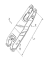
作業機械のリフトアーム組立体
図7及び図8を参照すると、リフトアーム組立体20は、基部リフトアームセグメント128と先端リフトアームセグメント130とを含む。リフトアーム組立体は、基部リフトアームセグメント128により定められたフレーム側端部246、先端リフトアームセグメント130により形成された作業具側端部248とを含む。リフトアーム組立体20は左側の基部伸長部174、右側の基部伸長部176、左側の先端伸長部178及び右側の先端延長部180(矢印475の概略的方向に見て)を含む。さらに、リフトアーム組立体20は、中に左フレームピンボア138が形成された左フレームカップリング136と、右フレームピンボア192が中に形成された右フレームカップリング190、左ピンボア142が中に形成された左側作業具カップリング140及び中に右側作業具ピンボア308が形成された右側作業具カップリング194とを含む。さらにリフトアーム組立体20は、リンケージピンボア132、リンケージピンボア133(図11参照)、リンケージピンボア134、リンケージピンボア135(図11参照)、シリンダピンボア186、スロット172(図8参照)を含む。
【0018】
基部リフトアームセグメント128は、これから伸長する左側の基部伸長部174と右側の基部伸長部176とを有する。左側の基部伸長部174と右側の基部伸長部176とは、これらの間にレバー空間292を形成するように相互に離れている。左側に基部伸長部174には、リンケージピンボア132とシリンダピンボア186とが形成されている。右側に基部伸長部176がリンケージピンボア133(図11参照)を中に有する。シリンダピンボア(図示せず)がシリンダピンボア186とほぼ同一の右側に基部伸長部176に形成されている。左フレームカップリング136が左側基部延長部174の一端に固定されている。右フレームカップリング190が右側基部伸長部176の一端に固定されている。
【0019】
先端リフトアームセグメント130は、これから伸長する左側の先端伸長部178と右側の先端伸長部180とを有する。左側の先端伸長部178と右側の先端伸長部180とは、これらの間にリンク空間294を形成するように相互に離れている。左側に先端伸長部178には、リンケージピンボア134が中に形成されている。右側に先端伸長部180は、リンケージピンボア135(図11参照)を中に有する。左側作業具カップリング140が左側に先端延長部178の一端に固定されている。右側作業具カップリング194が右側に先端伸長部180の一端に固定されている。
【0020】
構造的にリフトアーム組立体20は、ボックスブームリフトアームである。本明細書において、ボックスブームリフトアームとは、リフトアーム組立体が(i)ほぼ中空の内部を有し、(ii)リフトアーム組立体の構造が、図7及び図8に図示するようにリフトアーム組立体の長さに沿って,相当な距離だけ伸長するほぼ長方形状の断面を有するように、複数の金属板から製造されたリフトアーム組立体のことを意味する。
ボックスブームリフトアームを利用することの利点は、異なる構造的設計を利用するほぼ同重量のリフトアーム組立体よりも一般的に剛性であり、強度が強いことである。例えば、ボックスブームリフトアームを利用するリフトアーム組立体は、異なる構造的設計を利用するほぼ同重量のリフトアーム組立体よりも一般的に剛性であり、強度が強い。
【0021】
図9に図示するように、左基部伸長部174は、ボックスブームリフトアームの構造的特徴を概略的に図示する。詳細には、左基部伸長部174は、サイドプレート146、サイドプレート148、アンダープレート160、中間プレート166及びオーバプレート158を含む。
サイドプレート146の底部エッジ162は、アンダープレート160から上方に延びるようにアンダープレート160に固定されている。同様に、サイドプレート148の底部エッジ164は、アンダープレート160から上方に延びるようにアンダープレート160に固定されている。オーバプレート158はサイドプレート146の上部エッジ154に固定されている。オーバプレート158は、またサイドプレート146の上部エッジ156に固定されている。オーバプレート158がアンダープレート160とほぼ平行な関係になるようにサイドプレート146とサイドプレート148に固定される。中間プレート166がオーバプレート158とアンダープレート160とほぼ平行な関係に配置されるように、サイドプレート146とサイドプレート148との間に挟まれ、固定されている。上述の手段で、サイドプレート146、サイドプレート148、オーバプレート158、アンダープレート160を構成し、固定することは、左基部伸長部174が実質的に中空の内部144とほぼ長方形状の断面を有することになる。
【0022】
右基部伸長部176を含む基部リフトアームセグメント128は左基部伸長部174に記載されているものと同類の構造的特徴を有する。さらに、左基部伸長部178と右先端伸長部180とを含む先端リフトアームセグメント130は、左基部伸長部174に記載されているものと同類の構造的特徴を有する。このために、リフトアーム組立体20は、(i)ほぼ中空の内部を有しており、(ii)リフトアーム組立体20の構造は、リフトアーム組立体20の全長にほぼ沿って延びるほぼ長方形状の横断面を有する。
【0023】
図10及び11を参照すると、手順203がリフトアーム組立体20(図7参照)を製造するのに使用されている。手順203は、基部リフトアームセグメント128と先端リフトアームセグメント130が形成される段階204で開始する。基部リフトアームセグメント128と先端リフトアームセグメント130は、リフトアーム組立体20の(図7参照)2つの独立した別個のサブ組立体として形成されている。詳細には、基部リフトアームセグメント128が、左基部伸長部174と右基部伸長部176を含むように、図7、8及び9を参照して上述に記載するように形成されている。さらに、基部リフトアームセグメント128が溶融エッジ300を(図11参照)含むように生成されている。
【0024】
先端リフトアームセグメント130は、左先端伸長部178と右先端伸長部180とを含むように形成されている。さらに、先端リフトアームセグメント130が溶接エッジ302を含むように形成されている。
基部リフトアームセグメント128と先端リフトアームセグメント130とが形成される順番は、本発明に関し重要ではないことに留意しなければならない。すなわち、基部リフトアームセグメント128は先端リフトアームセグメント130前後又は同時に形成できる。
【0025】
更に、段階204は、基部リフトアームセグメント128と先端リフトアームセグメント130にカップリングを溶接する段階を含む。詳細には、左フレームカップリング136が左基部伸長部174に溶接されており、右フレームカップリング190が、基部リフトアームセグメント128の生成中に、右基部伸長部176に溶接される。同様な手段で、先端リフトアームセグメント130を形成中に、左側作業具カップリング140が左先端伸長部178に溶接され、右側作業具カップリング194が右先端延長部180に溶接される。カップリングが溶接される順番は、本発明に関し重要なことではないことに留意しなければならない。
【0026】
段階204の完了後、手順203における次の段階が段階206である。段階206において、リンケージピンボア132、リンケージピンボア133(図11参照)、シリンダピンボア186、及び右基部伸長部176内に形成されたシリンダピンボア(図示せず)と、が基部リフトアームセグメント128内に形成される。さらに、リンケージピンボア134とリンケージピンボア135とが(図11参照)が先端リフトアームセグメント130内に形成される。詳細には、加工コンプレックスが、右基部伸長部176内に形成されたリンケージピンボア133とシリンダピンボア(図示せず)とを形成するのに使用してもよい。
【0027】
加工コンプレックスは、先端リフトアームセグメント130の左先端伸長部178内に形成し、リンケージピンボア135を右先端伸長部180に形成するのにも用いられる。さらに、加工コンプレックスは、ピンボア138、142、192及び308(図8参照)を形成するのに用いることができる。
段階206の終了後に遂行される、手順203の次の段階が208である。段階208において、基部リフトアームセグメント128は、先端リフトアームセグメント128に溶接される。詳細には、基部リフトアームセグメント128は、基部リフトアームセグメント128の溶接エッジ300(図11参照)と先端リフトアームセグメント130の溶接エッジ302(図11参照)とが接触するように。先端リフトアームセグメントに対し配置される。段階206において形成された上述に記載のボアは、複数のピン(図示せず)に関連するものとして、かつ溶接エッジ300と溶接エッジ302が接触するように基部リフトアームセグメント128を先端リフトアームセグメント130に対し配置するようための固定装置(図示せず)として使用されることに留意しなければならない。溶接エッジ300と302は溶接シーム304(図7及び図8参照)を形成するようにともに溶接され、基部リフトアームセグメント128を図7及び図8に図示するように先端リフトアームセグメントに固定する。
【0028】
以下、リンケージーピンボア132、リンケージピンボア133、シリンダピンボア186、リンケージピンボア134、リンケージピンボア135、および右基部伸長部176に形成されたシリンダピンボアを、まとめてピンボアとする。実行段階210(すなわち先端リフトアームセグメント130に対し基部リフトアームセグメント128を溶接する段階)の前の手順203の実行段階206は、いくつかの利点を与える本発明の重要な1態様である。
詳細には、基部リフトアームセグメント128は、リフトアーム組立体20に比較すると比較的小さい。同様に、先端リフトアームセグメント130は、リフトアーム組立体20に比較すると比較的小さい。詳細には、基部リフトアームセグメント128は、リフトアーム組立体20の長さL7(図7参照)に比較すると、より短い長さL8(図11参照)を有し、先端リフトアームセグメント130も、リフトアーム組立体20の長さL7(図7参照)に比較すると、より短い長さL4(図11参照)を有する。リフトアーム組立体20または基部リフトアームセグメント128のような構造において(すなわち段階206)ピンボアを形成するのに要求される加工コンプレックスの大きさは、構造の大きさに正比例する。例えば、リフトアーム組立体20は基部リフトアームセグメント128よりも大きい(例えば長い)ので、基部リフトアームセグメント128においてピンボアを形成するのに比較すると、より大きな加工コンプレックスがリフトアーム組立体20においてピンボアを形成するのに要求されることになる。
【0029】
より大きな加工コンプレックスがより小さな加工コンプレックスよりも極めて高価であることに留意しなければならない。より大きな加工コンプレックスを使用することは、リフトアーム組立体20の製造コストを高いものにする。本発明では、比較的小さな加工コンプレックスを用いて、基部リフトアームセグメント128と先端リフトアームセグメント130にピンボアを形成し、次いで、基部リフトアームセグメント128と先端リフトアームセグメントを溶接して比較的大きな(すなわち長い)リフトアーム組立体20構造を形成することによって製造コストを減少させることになる。
【0030】
手順203の終了後、リフトアーム組立体20は作業機械10のフレーム16に(図1および13参照)に固定される。詳細には、図13においてリフトアーム組立体20のフレーム端部246が、(i)左側フレームカップリング136(図2参照)がフレーム16の側壁部分26と中央壁部分40との間に配置され (ii)右側フレームカップリング190(図8参照)が中央壁部分40とフレーム16の側壁部分32との間に配置されるように、フレーム16に対し配置される。リフトアーム組立体20が、上述したように、左側フレームカップリング136(図7参照)の左側フレームピンボア138(図7参照)と、右側フレームカップリング190(図8参照)の右側フレームピンボア192(図8参照)がフレーム16のボア孔28(図2参照)、ボア孔42(図2参照)及びボア孔34(図2参照)と線形に整列するように配置される。フレームピン260が、次いで、ボア孔28、ボア孔42、ボア孔34、左フレームピンボア138(図8参照)及び右フレームピンボア192(図8参照)を通り、左基部伸長部174と右基部伸長部176(リフトアーム組立体20)をフレーム領域296においてフレーム16にピボット運動可能に結合することになる。
【0031】
以下に詳細に記載するように、リフトアーム組立体20は、所定の作業用途のために設計されている。例えば、リフトアーム組立体20は、農業製品のような比較的低密度の物体を持ち上げるのに使用されるのが好ましい。しかし、図11及び12に図示するように、他のリフトアーム組立体の構造も手順203を用いて製造することができる。詳細には、他の先端リフトアームセグメント218を、手順203の段階210において、先端リフトアームセグメント130と取り替えることができる。このために、先端リフトアームセグメント218は、先端リフトアームセグメント130ではなく基部リフトアームセグメント128に溶接される。先端リフトアームセグメント218を基部リフトアームセグメント128に溶接することは、図12に図示するように別のリフトアーム組立体214を作り出すことになる。
【0032】
他のリフトアーム組立体214は、リフトアーム組立体20に関し上述したような同一の手段でフレーム16にピボット運動可能に結合されることを理解しなければならない。なぜならば、リフトアーム組立体214とリフトアーム組立体20はほぼ同一の基部リフトアームセグメント(すなわち、基部リフトアームセグメント128)を有しているからである。しかし、先端リフトアームセグメント130と先端リフトアームセグメント218との違いは、先端リフトアームセグメント130が長さL4(図11参照)を有し、先端リフトアームセグメント218が長さL5を有することである。長さL4はL5よりも大きい。基部リフトアームセグメント128は一定であるために、先端リフトアームセグメント218を基部リフトアームセグメントに溶接することにより、リフトアーム組立体214は、リフトアーム組立体20の長さL7(図7参照)よりも小さい長さL6(図12参照)を有することになる。リフトアーム組立体214のより短い長さL6のために、リフトアーム組立体214はリフトアーム組立体20に比較すると土壌、岩のような比較的高密度の物体を持ち上げるのにより適することになる。
【0033】
基部リフトアームセグメント128の物理的構造を一定状態に保ちながら、基部リフトアームセグメントに溶接するために別の複数の先端リフトアームセグメントの構造(例えば、先端リフトアームセグメント130,218)を形成することは、本発明の別の利点であることを理解しなければならない。詳細には、基部リフトアームセグメント128の物理的構造を一定状態に保ちながら、別のいくつかの先端リフトアームセグメント構造を形成することは、広い範囲の用途のために設計されたリフトアーム組立体を作り利用するための経済的方法を与えることになる。例えば、標準化された基部リフトアームセグメント128の構造を有することは、リフトアーム組立体20と214のような異なるリフトアーム組立体構造を、フレーム16を変更することなく作業機械10に利用できる。フレーム16が基部リフトアームセグメント128と協働するように設計されていること、これの物理的特徴(例えば。ピンボアの位置)が一定であるために、このことは確実なことである。従って、作業機械10には、フレーム16を変更することなく、リフトアーム組立体20又は他のリフトアーム組立体214を形成できる。フレーム16を変更することなく、いくつかのリフトアーム組立体構造のいずれかを利用できることは、作業機械10の能力を更に高めることになる。
【0034】
上述したように、ボックスブームリフトアーム式のリフトアーム組立体(すなわちリフトアーム組立体20)を製造するための手順203を利用することは、いくつか利点を有する。しかし、手順203は、スラブタイプのリフトアーム組立体のような別のタイプのリフトアーム組立体を製造するのに用いることができる。
【0035】
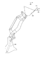
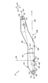
作業機械のリンケージ組立体
図7、8、及び13を参照すると、リンケージ組立体22がリフトアーム組立体20、リフトシリンダ250、リフトシリンダ328、リアティルトリンク256、リアティルトレバー262、及びティルトシリンダ270を含む。リンケージ組立体22は、フロントティルトレバー276、フロントティルトリンク282、及び作業具カップラー290を含む。
【0036】
図13及び図14を参照すると、リフトシリンダ250はフレーム端部252とリフトアーム端部254とを有する。リフトシリンダ250は、フレーム252がフレーム16の内部空間38内に配置され、側壁部分26のボア孔66(図2参照)に隣接して配置されるように、フレーム16に対し配置されている。リフトシリンダ250は、これが床板70のコンポーネント孔70(図3参照)を通って延びるようにフレーム16に対し配置されている。次いで、ピン310がリフトシリンダ250をフレーム16にピボット運動可能に結合できるようにボア孔66とフレーム端部252とを通って挿入される。
【0037】
リフトシリンダ250は、リフトアーム端部254がリフトアーム組立体20のスロット172(図8参照)を通って挿入されるように、そしてピンボア186(図8参照)に隣接して配置されるようにリフトアーム組立体20に対し配置される。ピン312は、リフトシリンダ250をリフトアーム組立体20にピボット運動可能に結合するようにシリンダピンボア186とリフトアーム端部254とを通って挿入される。
リフトシリンダ328は、リフトシリンダ250に記載されたのとほぼ同一の手段で、フレーム16とリフトアーム組立体20にピボット運動可能に結合される。詳細には、リフトシリンダ328はフレーム端部(図示せず)とリフトアーム端部(図示せず)を有する。リフトシリンダ328は、フレーム端部がフレーム16の内部空間38内に配置されており、側壁部分23の孔68(図5参照)に隣接して配置されるように、フレーム16に対し配置されている。リフトシリンダ328は、リフトシリンダ328が床板70のコンポーネント孔74を通って延びるように、フレーム16に対し配置されている。ピン(図示せず)が孔68(図5参照)とリフトシリンダのフレーム端部を通って挿入されて、リフトシリンダ328をフレーム16にピボット運動可能に結合するようになっている。
【0038】
リフトシリンダ328は、これのリフトアーム端部(図示せず)が、リフトアーム組立体20の右基部伸長部176内に形成されたスロット(図示せず)を通って挿入されており、中に形成されたシリンダボア(図示せず)に隣接して配置されるように、リフトアーム組立体20に対し配置されている。ピン(図示せず)がシリンダピンボアとリフトアーム端部を通って挿入されており、リフトシリンダ328をリフトアーム組立体20にピボット運動可能に結合するようになっている。
【0039】
図7及び8を参照すると、リアティルトレバー262が、プレート314、プレート316及び横方向チューブ部材317を含む。プレート314は、孔320と孔322とを含み、これらの孔320と孔322は、プレート314の対向する端部に配置される。プレート314は中を貫通するアパーチュア326(図8参照)も有する。アパーチュア326は、孔320と孔322との間に配置されている。
プレート316は、ほぼプレート314と同一に構成されている。詳細には、プレート316は、これの一端に形成された孔324を有する。プレート316は、孔324を有する端部に対向したプレート316の端部に形成された他の孔(図示せず)も有する。プレート316は、またこれを通るアパーチュア(図示せず)も有する。プレート316に形成されたアパーチュアは孔324と別の孔(図示せず)との間に配置されている。
【0040】
プレート314とプレート316は、プレート318(図7参照)がこれらの間に配置されるようなほぼ平行な関係で相互に間隔が空けられている。横方向チューブ部材317がプレート空間318内に配置されており、横方向のチューブ部材317により形成された導管(図示せず)が、プレート314内に形成されたアパーチュア326とプレート316に形成されたアパーチュアに対し線形に整列するようにプレート314とプレート316とに固定されている。プレート314とプレート316は、孔320と324が線形に整列するように相互に配置されている。プレート314と316は、孔322と、中に孔324が形成されたプレートに対向したプレート316の端部に形成された孔が線形に整列するように相互に配置されている。
【0041】
リアティルトレバー262は、横方向チューブ部材317と、プレート314及び316に形成されたアパーチュア(すなわち、アパーチュア326及びプレート136に形成されたアパーチュア(図示せず))が、左基部伸長部174に形成されたリンケージピンボア132、右基部伸長部176に形成されたリンケージピンボア133と線形に整列する。リアティルトレバー262は、リフトアームヤティルトレバー262がレバー空間292を通って延びるようにレバー空間292内に配置される。リアティルトレバー262は、さらにリフトアームヤティルトレバー262がレバー空間292を通って延びるように、レバー空間292内に配置されている。リフトアームヤティルトレバー262を上述の手段で配置することにより、シリンダ端部264とリアティルトレバー262のリンク端部266がレバー空間292から出るように延びることになる。
【0042】
図4に図示するように、ピン330がリンケージピンボア132、横方向チューブ部材317、プレート314とプレート316において形成されたアパーチュア(すなわちアパーチュア326及びプレート316(図示せず)において形成されたアパーチュア(図示せず))及びリンケージピンボア133(図11参照)を通って挿入され、シリンダ端部264とリンク端部266との間に挟まれたリアティルトレバー262をリフトアーム組立体20にピボット運動可能に結合するようになっている。
【0043】
図8を参照すると、リアティルトリンク256が、プレート332、プレート334、及びボス336を含む。プレート332は、該プレートの一端に形成された孔338と、これに対向する端部に形成された孔344とを有する。詳細には、プレート334は、これらの各端部に形成された孔を有しているが、孔340のみが図示されている。プレート空間342が間に形成されるように、プレート332とプレート334がほぼ平行な関係で相互に離れている。ボス336がプレート空間342内配置されており、ボス336により形成された通路(図示せず)が、プレート332内の孔344と、プレート334に形成された孔(図示せず)と線形に整列するように、プレート332とプレート334に固定されている。プレート332とプレート334が、孔338と340が線形に配列されるように相互に配置される。
【0044】
リアティルトリンク256は、端部258と端部260とを有する。リアティルトリンク256がリアティルトレバー262のリンク端部266に対し配置され、リアティルトリンク256の端部260がリアティルトレバー262のプレート空間318(図7参照)内に配置されるようになっている。リアティルトリンク256は、リアティルトレバー262のリンク端部266に対し配置されており、プレート332内の孔34、プレート334内に形成された孔(図示せず)、ボス336により形成された通路(図示せず)及びリアティルトレバー262に形成された孔(すなわち、孔322及びプレート316(図示せず)に形成された孔が線形に整列されている。
【0045】
図13及び図14に見られるように、ピン346がプレート332(図8参照)内の孔344、プレート334内に形成された孔(図示せず)、ボス336によって形成された通路(図示せず)、及びリアティルトレバー262内に形成された孔(すなわち孔322とプレート316に形成された孔(図示せず))を通って挿入され、リアティルトレバー262のリンク端部266に、リアティルトリンク256をピボット運動可能に結合するようになっている。
リフトアームやティルトリンク256の端部258は、フレーム16の中央壁部分40が、ティルトリンク256のプレート332とプレート334との間に挟まれるように、フレーム16に対し配置されている。リアティルトリンク256の端部258は、プレート332内に形成された孔338(図8参照)とプレート334(図8参照)内に形成された孔340が中央壁部分40(図2参照)内に形成された孔44と線形に整列するようにフレーム16に対し配置されている。ピン348が側壁部分26(図2参照)のアクセス孔30、リアティルトリンク256の孔338及び340、中央壁部分40の孔44,及び側壁部分32(図2参照)のアクセス孔36を通って挿入され、フレーム領域296(図13参照)の下側に垂直方向に配置されたフレーム領域298においてフレーム16にリアティルトリンク256の端部258をピボット運動可能に結合するようになっている。
【0046】
図7と8をもう一度参照すると、フロントティルトリンク282がレバー端部284とリフトアーム端部286を有する。レバー端部284は、内部に孔352が形成されており、リフトアーム端部286は中に形成された孔(図示せず)を有する。フロントティルトリンク282がリンクスペースに延びるようにリフトアーム組立体20に対し配置されている。フロントティルトリンク282は更に、リフトアーム端部286に形成された孔が、左先端伸長部178(図11参照)に形成されたピンボア134と、右先端伸長部180(図11参照)に形成されたリンケージピンボア135と線形に整列するようにリフトアーム組立体20に対し配置されている。図13及び図15において図示するように、ピン350がリンケージピンボア134(図11参照)、フロントティルトリンク282のリフトアーム端部286内に形成された孔(図示せず)、およびリンケージピンボア135(図11参照)を通り挿入されており、フロントティルトリンク282のリフトアーム端部286をリフトアーム組立体20にピボット運動可能に結合するようになっている。
【0047】
図7と8を参照すると、フロントティルトレバー276がプレート354、プレート356、ボス359、後端部278、及び前端部280とを含む。プレート354は、一端部に孔361を有しており、他端には孔363が形成されている。プレート354は、これを貫通するアパーチュアを有する。プレート354に形成されたアパーチュア369が、孔361と363との間に配置されている。プレート356は、プレート356に関し記載しているのとほぼ同一の手段で構成されている。詳細には、プレート356は一端において孔365と、他端に形成された孔(図示せず)とを有する。プレート356は、また、これを貫通して形成されたアパーチュア(図示せず)を有する。プレート356において形成されたアパーチュア(図示せず)が、孔365と図示していない孔との間に配置されている。プレート356とプレート354はほぼ平行な状態で相互に配置されており、プレート空間371がこれらの間に形成されている。ボス359がプレート空間371内に配置されており、ボス359を通って形成された通路(図示せず)が孔363と、プレート356端部に形成された孔(図示せず)と線形に整列するように、プレート354と356に固定されている。プレート354とプレート356は、孔361と365が線形に整列され、アパーチュア369と、プレート356内に形成されたアパーチュアが線形に整列するように相互に配置されている。
【0048】
フロントティルトレバー276は、フロントティルトリンク282がプレート空間371内に配置されるようにフロントティルトリンク282に対し配置されている。フロントティルトレバー276は、プレート354内に形成されたアパーチュア369、フロントティルトリンク282内に形成された孔352、及びプレート356内に形成されたアパーチュア(図示されず)が線形に整列するようにフロントティルトリンク282に対し配置されている。ピン373(図14参照)がアパーチュア369、孔352及びプレート356内に形成されたアパーチュア(図示されず)を通って挿入される。ピン373は、フロントティルトリンク282のレバー端部284を、フロントティルトレバー276の後端部278と前端部280との間に位置する位置288においてフロントティルトレバー276にピボット運動可能に結合されている。
【0049】
図13及び図14を参照すると、ティルトシリンダ270はレバー端部272と作業具端部274とを含む。ティルトシリンダ270は、レバー272がプレート空間318(図7参照)内に配置されるようにリアティルトレバー262のシリンダ端部264に対し配置されている。ピン375が、ティルトシリンダ270のレバー端部272をリアティルトレバー262のシリンダ端部にピボット運動可能に結合するように、孔320(図7参照)、レバー端部272及び孔234に挿入される。
【0050】
更にティルトシリンダ270は、作業具端部274がプレート空間371内に配置され、孔365と361との間に配置されるようにフロントティルトレバー276に対し配置されている。次いで、ピン377が、ティルトシリンダ270の作業具端部274をフロントティルトレバー276のリア端部278にピボット運動可能に結合するように、孔365、作業具端部274、孔361を通って挿入される。上述に記載のようにティルトシリンダ270を結合することは、ティルトシリンダ270の作業具端部274を作業機械18に機械的に結合することになることを理解しなければならない。
リンケージ組立体22は、既存のリンケージ組立体に比較すると、作業具18をフレーム16に機械的に結合するための比較的コンパクトな機構を提供することを理解しなければならない。リンケージ組立体がコンパクトであるために、既存のリンケージ組立体(例えば図22参照)に比較すると図21に図示するようにオペレータは、キャブ組立体12から作業領域を比較的妨害されることなく見ることができる。
【0051】
さらに、リンケージ組立体の上述に記載の成分は、既存のリンケージ組立体に比較すると、矢印379及び381(図14参照)により示された方向に作業具18の動きの範囲をより広くすることができる。上述に記載のようにより大きな程度に作業具18を回転させることができることは、他の作業具とともに能力を改善することになる。さらに、上述に記載のリンケージ組立体22成分の構造は、図14の矢印379,381により図示された作業具18の動作の全範囲にわたり比較的一定のティルト力を与える。
【0052】
更に、図14及び15に図示するように、ティルトシリンダ270は、水平線383と、作業具18の床セグメント385により形成される面の線形伸長部387との交差する点が所定の角度Θを形成するように、作業具18を位置決めするように伸長できる。リンケージ組立体22によって、作業具18を所定の角度Θに維持しながら、リフトアーム組立体20が図15に図示するように高く伸ばすことができることに留意しなければならない。作業具18を持ち上げながら、所定の角度Θに維持することは、作業機械10のオペレータが掘削作業中に作業具18内に含まれた積載物を投げ出すようなことが少なくなる。作業具18を、持ち上げながら、所定の角度Θに維持するリンケージ組立体22の能力が本発明の利点である。なぜならば、リフトアーム組立体を上昇させながら、水平線(水平線383に類似する)に対し所定の角度に作業具を維持するために、既存リンケージ組立体では、一般的に付加的な機械的又は油圧的成分を必要とするからである。これらの付加的成分は、リンケージ組立体22に比較すると、機械的複雑さとこれらの既存のリンケージ組立体の費用を高くする。
【0053】
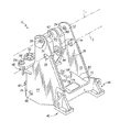
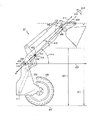
作業機械の作業具カップラー
図13、23及び24を参照すると、作業具カップラー290が図示されている。作業具カップラー290は、リンケージを22を作業具18に接続するように作用する。詳細には、作業具カップラー290は、リンケージ22と作業具18の媒介物である。さらに、作業具カップラー290は作業具18をリンケージに簡単に取りつけたりはずすことができるようにする。
【0054】
作業具カップラー290は、右外側支持プレート460、右内側支持プレート462、左内側支持プレート464及び左外側支持プレート466(矢印475の方向から見て)を含む。中央ボックスセクション468が、内側右支持プレート462と左内側右支持プレート464の下側部分に溶接されている。リアボックスセクション480(図13参照)が右外側支持プレート460、右内側支持プレート462、左内側支持プレート464及び左外側支持プレート466の下側部分に溶接され、各支持プレートがほぼ平行になっている。センターボックスセクション468とリアボックスセクション480が、リフト作業中に物体を作業具18からリンケージ22に搬送するような構造を形成する。
チューブセクション470が、右外側支持プレート460、右内側支持プレート462、左内側支持プレート464、左外側支持プレート466の上側部分に溶接されている。右支持バー472が、右外側支持プレート460に固定されており、矢印476の方向に外方向に延びている。同様に、左支持バー474は左外側支持プレート466に固定され、矢印478の方向に外側に延びている。
【0055】
右内側支持プレート462は、チューブセクション470と中央ボックスセクション480との間に位置する右ティルトピンボア484を有している。左内側支持プレート464は、チューブセクション470と中央ボックスセクション480との間に位置する左ティルトピン貫通ボア485を有する。右ティルトピンボア484と左ピンボアボア485は、ティルトピン486が右ティルトピンボア484と左ティルトピンボア485を通って挿入できるように線形に整列されることに留意しなければならない。さらに、ティルトピンボアファスナー(図示せず)がティルトピン486を右内側支持プレート462と内側支持プレート464とに固定でき、ティルトピン486が矢印476と478の方向に動かないようにする。
【0056】
右内側支持プレート460は、これを貫通して形成された右外側作業具ピンボア492を有し、右内側支持プレート462は、中央ボックスセクション480近くに位置する地点でこれを貫通して形成された右内側作業具ピンボア492を有する。同様に、左内側支持プレート464は、これを貫通して形成された右内側作業具ピンボア496を有し、左外側支持プレート466は、中央ボックスセクション468近くに位置する地点でこれを貫通して形成された外側作業具ピンボア498を有する。右外側作業具ピンボア492、右内側ピンボア496及び左外側作業具ピンボア498は、右側作業具ピン500が右外側作業具ピンボア492、右内側作業具ピンボア494とを通って、中央ボックスセクション468に挿入され、左側作業具ピン501が左外側作業具ピンボア498、左内側作業具ピンボア498とを通って、中央ボックスセクション468に挿入されるように、線形に整列される。さらに、右作業具ピンファスナー(図示せず)が右側作業具ピン500を右外側支持プレート4600と右内側支持プレート462とに固定し、右作業具ピン500が矢印476と478の方向に動かないようにしている。同様に、左作業具ピンファスナー(図示せず)が左側作業具ピン501を左外側支持プレート466と左内側支持プレート464とに固定し、左作業具ピン501が矢印476と478の方向に動かないようにしている。
【0057】
カップラーシリンダがリアボックスセクション内に配置されており、このカップラーシリンダは、右半分カップラーシリンダ481(仮定線で図示する)と左半分カップラーシリンダ479(仮定線で図示する)とに分割されている。あるいは、左係合ピン488は左半分カップラーシリンダ479の可動ロッドと一体に形成してもよい。油圧流体が左半分カップラーシリンダ479の一端側に導入されると、該油圧流体は、左係合ピン488を矢印476の方向に動かし、油圧流体が左半分カップラーシリンダ479の他端側に導入されると、該油圧流体は、左係合ピン488を矢印478の方向に動かす。左半分カップラーシリンダ479が矢印476の方向に左係合ピン488を動かすと、左係合ピン488が図24に図示するように第1のピン位置に配置される。この第1のピン位置において、左係合ピン488は、作業具18から離れた位置において左外側支持プレート466内に形成された左第2カップリングアパーチュア490を通って延びることができない。左半分カップラーシリンダ479が左係合ピンを矢印478の方向に動かすと、左係合ピン488が図23に図示するように、第2のピン位置に配置される。この第2のピン位置において、左側係合ピン488は、左外側支持プレート466内に形成された第2のカップリングアパーチュア490を通って延びる。
【0058】
同様に、右係合ピン487が、右半分カップラーシリンダ481の可動ロッド(図示せず)に固定されている。あるいは、右係合ピン487は右半分カップラーシリンダ481の可動ロッドの一端部に一体に形成してもよい。油圧流体が右半分カップラーシリンダ481の一端側に導入されると、該油圧流体は、右係合ピン487を矢印478の方向に動かし、油圧流体が右半分カップラーシリンダ481の一端側に導入されると、該油圧流体は、矢印476の方向に右係合ピン487を動かすことができる。右半分カップラーシリンダ481が矢印478の方向に右係合ピン487を動かすと、右係合ピン487が第1のピン位置に配置される(図示せず)。この第1のピン位置においては、右係合ピン487は、作業具18から離れた位置において右外側支持プレート460内に形成された右第2カップリングアパーチュア(図示せず)を通って延びることができない。右半分カップラーシリンダ481が右係合ピン487を矢印476の方向に動かすと、右係合ピン487が図21に図示するような第2のピン位置に配置される。第2のピン位置において、左側係合ピン487は、右外側支持プレート460内に形成された第2カップリングアパーチュアを通って延びる。
【0059】
作業具カップラー290は、右作業具ピン500と左作業具ピン501とによりリフトアーム組立体20にピボット運動可能に結合されている。詳細には、作業具カップラー290の右外側作業具ピンボア492と右内側作業具ピンボア494は、図7及び8に図示するようにリンケージ22の右作業具ピンボア308と整列しなければならず、作業具カップラー290の左内側の右外側作業具ピンボア496と左外側作業具ピンボア496は、図7及び8に図示するようにリンケージ22の左作業具ピンボア308と整列しなければならない。右側作業具ピン500が作業具カップラー290の右外側作業具ピンボア492を通り、リフトアーム組立体20の右側作業具ピンボア308を通リ、右内側作業具ピンボア494を通って作業具カップラー290の中央ボックスセクション468に挿入される。左作業具ピン501は、作業具カップラー290の左外側作業具ピンボア498を通り、リフトアーム組立体20の左側作業具ピンボア142を通リ、左内側作業具ピンボア496を通って作業具カップラー290の中央ボックスセクション468に挿入される。
【0060】
右作業具ピンファスナーは、右作業具ピン500を作業具カップラー290に固定し、右作業具ピン500が矢印476と478の方向に動かないようにし、左作業具ピンファスナーは、左作業具ピン501を作業具カップラー290に固定し、左作業具ピン501が矢印476と478の方向に動かないようにする。従って、作業具カップラー290は、これが図13に図示した矢印502、504の方向に右作業ピン500と左作業ピン501においてリフトアーム組立体20に対し自由に回転するように、リフトアーム組立体20にピボット運動可能に結合されている。
【0061】
作業具カップラー290は図13に図示するように、リンケージ22のフロントティルトレバー276にピボット運動可能に結合されている。詳細には、図7と8に図示するように、プレート354内の孔363、リンケージ22のプレート365内のボス359及び孔(図示せず)が、図24に図示したように作業具カップラー290の右側ティルトピンボア484と左側ティルトピンボア485に整列する。ティルトピン486は作業具カップラー290の右ティルトピンボア484、リンケージピン22のプレート365内の孔、リンケージ22のボス359、リンケージ22のプレート354内の孔363及び作業具カップラー290の左ティルトピンボア485を通って挿入される。ティルトピンファスナーは、ティルトピン486を作業具カップラー290に固定し、ティルトピン486が矢印476,478の方向に動かないようにしている。従って、作業具カップラー290は、図13に図示するように、矢印502,504の方向に、ティルトピン468においてフロントティルトレバー276に対し自由に回転するようになっている。
【0062】
作業具カップラー290は、右側作業具ピン500と左側作業具ピン501との周りを回転できる。詳細には、ティルトシリンダ270が図13に図示するように矢印506の方向に伸ばされると、フロントティルトレバー276が作業具カップラー290のティルトピン486を矢印506の方向に付勢するように、矢印506の方向に付勢される。ティルトピン486が矢印506の方向に付勢されると、作業具カップラー290が右作業具ピン500と左作業具ピン501との周りを矢印502の方向に回転する。一般的に、作業具カップラー290に取り付けられた作業具18から物体を投棄することが望まれるとき、作業具カップラー290が矢印502の方向に回転する。
【0063】
あるいは、ティルトシリンダ270が、図13に図示するように矢印508の方向に引き込まれると、フロントティルトレバー276が、作業具カップラー290のティルトピン486を矢印506の方向に付勢するように、矢印506の方向に付勢される。ティルトピン486が矢印508の方向に付勢されると、作業具カップラー290が右作業具ピン500と左作業具ピン501との周りを矢印504の方向に回転する。一般的に、作業具カップラー290に取り付けられた作業具18で物体をすくい上げることが望まれるとき、作業具カップラー290は矢印504の方向に回転する。
図23と24を参照すると、作業具18が、これに取り付けられた右ヒンジプレート510と左ヒンジプレート512を含む。右ヒンジプレート510が、これの上側部分に形成された右フック部分514を含む。右フック部分514は作業具カップラー290の右支持バー472に引っかかって係合するように構成されている。右ヒンジプレート510は、これに形成された右第1カップリングアパーチュア516を有する。右第1結合アパーチュア516は、図21に図示するように、作業具カップラー290の右係合ピン487を受取るように構成されている。
【0064】
同様に、左ヒンジプレート512は、これの上側部分に形成された左フック部分518を含む。左フック部分518は作業具カップラー290の右支持バー474にフックで係合するように構成されている。左ヒンジプレート512は、これに形成された左第1カップリングアパーチュア520を有する。左第1結合アパーチュア520は、作業具カップラー290の左係合ピン488を受取るように構成されている。
【0065】
作業具カップラー290を作業具18に結合するために、リフトアーム組立体20は作業具18の方向に動かされる。この後、左支持バー474が左ヒンジプレート512の左フック部分518の下側近くに配置され、右支持バー472が左ヒンジプレート510の右フック部分514の下側近くに配置される。
作業具290が矢印522の方向に持ち上げられると、左支持バー474が左ヒンジプレート512の左フック部分518と接触するように動かされ、左ヒンジプレート512が図23に図示するように作業具カップラー290に引っかけられて係合するようになっている。同様に、作業具290が矢印522の方向に持ち上げられると、右支持バー472が右ヒンジプレート510の右フック部分514と接触するように動かされ、右ヒンジプレート510が図23に図示するように作業具カップラー290に引っかけられて係合するようになっている。
【0066】
作業具18が作業具カップラー290に引っかけられて係合されると、作業具18は左支持バー474と右支持バー472との周りを図23に図示するように自由に回転する。
作業具カップラー29が矢印522の方向に動くと、作業具18は、図23に図示するように作業具290を係合位置に配置するように、矢印528の方向に回転する。係合位置において、左ヒンジプレート512の第1カップリングアパーチュア520が作業具カップラー290の左第2カップリングアパーチュア490と整列され、右ヒンジプレート510の右第1カップリングアパーチュア516が作業具カップラー290の右第2カップリングアパーチュア(図示せず)と整列される。
【0067】
作業具カップラー290を作業具18に固定して取り付けるために、作業具カップラー290の左係合ピン488と右係合ピン487は作業具18と係合しなければならない。詳細には、左半分カップラーシリンダ479は左係合ピン488を、図24に図示するように左係合ピン488が左第1カップリングアパーチュア520から離れる第1のピン位置から、図23に図示するような第2のピン位置に、ほぼ矢印478の方向に動かす。詳細には、左係合ピン488が作業具カップラー290の左第2カップリングアパーチュア490と、作業具18の左第1カップリングアパーチュア520とを通って進み、作業具18が左支持バー474の周りをほぼ矢印526と528との方向に回転しないようにする。
【0068】
同様に、右半分カップラーシリンダ481は、右係合ピン487を、右係合ピン487が右第1カップリングアパーチュア516(図示せず)から離れる第1のピン位置から、図21に図示するように第2のピン位置に、ほぼ矢印476の方向に動かす。詳細には、右係合ピン487が作業具カップラー290の右第2カップリングアパーチュアと、作業具18の左第1カップリングアパーチュア516とを通って進み、作業具18が右支持バー472の周りをほぼ矢印526と528との方向に回転しないようにする。
作業具カップラー290を作業具18からはずすために、作業具カップラー290の左係合ピン488と右係合ピン487は作業具18から係合が解除されなければならない。詳細には、左半分カップラーシリンダ479は左係合ピン488を、図23に図示するような第2のピン位置から、図24に図示するような左係合ピン488が左第1カップリングアパーチュア520から離れる第1のピン位置に、ほぼ矢印478の方向に動かす。同様に、右半分カップラーシリンダ481は、右係合ピン487を、図21に図示するように第2のピン位置から右係合ピン487が右第1カップリングアパーチュア516(図示せず)から離れる第1のピン位置に動かす。さらに、左支持バー474は、左フック部分518かと接触しないように動き、右支持バー472が図24に図示すように左フック部分514と接触しないように動く。
【0069】
図21と22を参照すると、狭いボックス式のリフトアーム20の使用に関連した作業具カップラー290の利点が図示されている。図21は、図1に図示した作業機械10のキャブ組立体12に配置されたシーと530に着座したオペレータの視界を図示している。着座位置からオペレータは作業具18が作業具カップラー290に結合されていることを確認できる。詳細には、オペレータは、右ヒンジプレート510の右フック部分514が作業具カップラー290の右支持バー472に引っかけられて係合されたことを確認できる。更に、オペレータは、作業具18の右ヒンジプレート510を通って延びる右係合ピン487の一端部分を矢印476の方向に見ることができる。さらに、オペレータは、左ヒンジプレート512の左フック部分518が作業具カップラー290の左支持バー474に引っかけられて係合されたことを確認できる。更に、オペレータは、作業具18の左ヒンジプレート512を通って延びる左係合ピン488の一端部分を矢印476の方向に見ることができる。
【0070】
図22は、例示的従来の連結式ローダのキャブ組立体に配置されたシートに着座したオペレータの視界を図示する。リフトアームは、一般的に、作業機械の前部に対するオペレータの視界の相当部分を遮るようになっている支持部とともに、右スラブアーム540と左スラブアームから構成される。作業具カップラーの右支持バーを引っかけて係合する右ヒンジプレートの右フック部分に関するオペレータの視界が532のほぼ全領域においてリンケージの一部により妨げられていることに留意する。さらに、作業具の右ヒンジプレートを通って延びる右係合ピンの端部に関するオペレータの視界は、533のほとんどの領域において、リンケージの一部により妨げられる。同様に、作業具カップラーの右支持バーを引っかけて係合する左ヒンジプレートの左フック部分に関するオペレータの視界が534のほぼ全領域においてリンケージの一部により妨げられていることに留意すべきである。さらに、作業具の左ヒンジプレートを通って延びる左係合ピンの端部に関するオペレータの視界は、535のほとんどの領域において、リンケージの一部により妨げられる。
【0071】
作業機械の伸長したリフトアーム
図16から図20までを参照すると、リフトアーム組立体20の2つの異なる伸長した構造が図示されている。図16、図18及び図20に図示されたリフトアームの第1の伸長した構造は本発明の例示的リフトアーム組立体20である。あるいは、図17及び図19に図示したリフトアーム組立体20’の第2の伸長した構造は、図12に図示したリフトアーム214に類似しているが、伸長した長さを有している。リフトアーム組立体20の第2の伸長した構造はリフトアーム組立体20の第1の伸長した構造の利点を証明するために示されている。
【0072】
図16〜図20のそれぞれは、リフトアーム組立体20の左側面図を表している。リフトアーム組立体20は左側から見られたとき共通の場所を共有するいくつかの成分を有する。例えば、左側フレームピンボア138が、図16〜図20のように左側から見たときに、右フレームピンボア192(図8参照)と同一場所に配置される。従って、説明を明白にするために、左側面から直接見える成分のみについて論議する。作業機械10の右側部から見た成分は、作業機械10の左側から見た成分とほぼ同一である。
左フレームピンボア138は、中心線としてフレームピン軸400を有する。フレームピン軸400は、リフトアーム組立体20がフレームに対し回転するような軸であることに留意しなければならない。詳細には、フレームピン260(図13参照)が上述したように、左フレームピンボア138と右フレームピンボア192とをフレーム16のピンボア28、42、34にピボット運動可能に結合し、このためにリフトアーム組立体20が矢印410と412の方向にフレーム16に対し回転できるようになる。
【0073】
同様に、左シリンダピンボア186が中心線としてシリンダピン軸線402を有する。シリンダピン軸線402は、リフトアーム組立体20に結合されると、このまわりに左リフトシリンダ250が回転するような軸線である。詳細には、リフトシリンダ250が伸ばされると、リフトアーム組立体20が図16、17に図示するように上側位置に付勢される。リフトアーム組立体20は、ピン312により左リフトシリンダ250のリフトアーム端部254にピボット運動可能に結合される。リフトアーム組立体20が上側位置に動くと、左リフトシリンダ250のリフトアーム端部254は、リフトシリンダ250の向きがリフトアーム組立体20にたいし変わるにつれ、シリンダピン軸402の周りを矢印412の方向に回転する。同様に、リフトシリンダ250が引き込まれると、左リフトシリンダ250のリフトアーム端部254は、リフトシリンダ250の向きがリフトアーム組立体20にたいし変わるにつれ、シリンダピン軸402の周りを矢印410の方向に回転する。
【0074】
第1のライン404は、フレームピン軸線400(フレームピンボア138により形成された)とシリンダピン軸線402(左シリンダピンボア186)により形成された)とを接続するラインである。
左作業具ピンボア142は、中心線として作業具ピンボア軸線408を有する。作業具18は図23及び図24に図示するように作業具ピン501によってピンボア142においてリフトアーム組立体20に取り付けられていることに留意しなければならない。作業具18は、さらにこれが矢印410と412の方向に動くとき、作業具ピンボア軸線408の周りを回転することに留意しなければならない。
【0075】
第2のライン416は、左作業具ピンボア142と左フレームピンボア138により形成されている。第2のライン416は、左フレームピンボア138により形成されたフレームピン軸線400と、左作業具ピンボア142により形成された作業具ピンボア軸線408を接続する。第2のライン416は第1のライン404上にあることに留意しなければならない。第1のライン404と第2のライン416はリフトアーム組立体20のリフト補角418を形成することにも留意しなければならない。
リフトアーム組立体20の第1の伸長構造は、約9度のリフト補角418を有することに留意しなければならない。リフトアーム組立体20'の第2の伸長構造は、約2度のリフト補角418を有する。
【0076】
以下の記載は、本発明の特徴を組み入れるリフトアーム組立体20の第1の伸長した構造に関する。
図20を参照すると、平面420は第1のライン404に対し垂直であり、シリンダ軸線402において、第1のライン404と交差する。平面420は、リフトアーム組立体20を、図20に図示するように、平面420に対し左側のフレーム側セグメント422と、平面420に対し右側の作業具セグメント424に分割する。
【0077】
左フレームピンボア138はリフトアーム組立体20のフレーム側セグメント422内にあり、左作業具ピンボア142はリフトアーム組立体20の作業具側セグメント424内にある。さらに、リフトアーム組立体20のフレーム側セグメント422は左フレームピンボア138においてフレーム16にピボット運動可能に結合されており、リフトアーム組立体20の作業具側セグメント424は左作業具ピンボア408において作業具18にピボット運動可能に結合されている。
平面420が左シリンダピンボア186を2つの等しいセグメントに分け、シリンダピンボアの186の第1の半分がリフトアーム組立体20のフレーム側セグメント422内にあり、シリンダピンボア186の第2の半分がリフトアーム組立体20の作業具側セグメント424内にある。
【0078】
第1のライン404が第1の線分428を有する。詳細には、ポイント426は、第1のライン404がリフトアーム組立体20の作業具側セグメント422の外周と交差するところに存在する。さらに、ポイント427が左シリンダピンボア286の遠い方の側部上にあり、第1のライン404が左シリンダピンボア186と交差する。第1の線分428は、ポイント427とポイント426との間にある第1ライン404の一部として形成される。更に、第1の線分428はリフトアーム組立体20の作業具側セグメント20の作業具側セグメントと完全に一致する。ここで、本明細書において使用する「完全に一致する」とは、全線分が図20に図示するように側面図に表したようなリフトアーム組立体20の外周内にある場合に、リフトアーム組立体と全く一致することを意味する。
【0079】
第1のラインは第2の線分436を有する。詳細には、点432は、左シリンダピンボア186の近い方にあり、第1のライン404が左シリンダピンボア186と交差している。さらに、点434は、左フレームピンボア138の遠い方にあり、左フレームピンボア138と交差している。第2の線分436は、点432と434の間にある第1のライン404の一部として形成される。さらに第2の線分436は、リフトアーム組立体20のフレーム側セグメント422と完全に一致する。
第1のライン404は、さらに中に第3の線分438が形成されている。詳細には、第3の線分438は、リフトアーム組立体20の作業具側セグメント424から離れた方向に延びる点426を超えた第1のライン404の一部として形成される。第3の線分438はリフトアーム組立体20とは完全に一致しているわけではない。詳細には、第3の線分438は、リフトアーム組立体20の作業具側セグメント424またはフレーム側セグメント422と完全に一致しているわけではない。第3の線分436は、図20に図示するように、リフト組立体20の作業具側セグメント424の外周の下側エッジの下側にあることに留意しなければならない。
【0080】
第2の線416は、第4の線分440を中に有する。詳細には、点442は、左フレームボア138の遠い側にあり、第2のライン416が左フレームピンボア138と交差している。さらに、点444は、左作業具ピンボア142の近い方にあり、第2のライン416が左作業具ピンボア142と交差している。第4の線分440は、点442と444の間にある第2のライン404の一部として形成される。さらに第2の線分440は、リフトアーム組立体20と完全に一致している。
図16から19を参照すると、水平線406は、地面446と平行なピンボア軸線400から延びている。第1のライン404と水平線406は、フレーム組立体16に対するリフトアーム組立体20の角度414を形成する。図16と17に図示するようなリフト角414は作業機械10の最大リフト角に相当する。図18と19に図示したリフト角414は、ライン416を地面446に平行に配置し、水平線406に一致する。
【0081】
フレーム16、リフトアーム組立体20およびリフトシリンダ250の所定の構造に関し、図16および17に図示するようにリフト角414の最大角がある。作業機械10のリフト角414の最大値は約44度である。リフト角414のこの最大角、補角418、およびリフトアーム組立体20のこの最大角は、作業機械10の2つの作動高さを決定する。最大リフト高さ454は、作業機械10が、第1に伸長されたリフトアーム組立体20の構造に関する作業具ピン軸線408を持ち上げることのできる最大高さである。最高リフト高さ455は、作業機械10が、第2に伸長されたリフトアーム組立体20’の構造に関する作業具ピン軸線408を持ち上げることのできる最大高さである。
【0082】
最高投棄高さ450は、リフトアーム組立体20の第1の伸長した構造で作業機械10の作業具18から積載物が投棄されるときの最高高さである。最高投棄高さ451は、リフトアーム組立体20’の第2の伸長した構造で作業機械10の作業具18から積載物が投棄されるときの最高高さである。
パレット等を移動させるの使用されるフォークのようないくつかの作業具に関し、最高リフト高さ454,455は、最高投棄高さ450,451よりも作業機械10の作動能力をより有効に測ることがきることに留意しなければならない。あるいは、嵩のある物体を牽引したり持ち上げるのに使用されるバケットのような他の作業具に関し、最高投棄高さ450,451は、最高投棄高さ454,455よりも作業機械10の作動能力をより有効に測ることがきることに留意しなければならない。
【0083】
図18及び図19は、アーム双方が同一の安定性を有することを示している。安定性は、作業機械10が横倒しになる可能性を予測できる。作業機械10が地面446から積載物を図16と17に図示するように上昇位置に持ち上げると、リフトアーム組立体20は、最高に不安定な点を通過しなければならない。最高不安定点は、物体のために発生したモーメントにより、作業機械10が最も横倒しする可能性のある点である。最高不安定点において、リフトアーム組立体20により運ばれる物体がフロントホイール430周りに最大のモーメントを作り出す。
フロントホイール430の周りの最高モーメント点は、作業具ピン軸線408が図18と図19に図示するように、フロントホイール430のアクスル435の右側までの最大距離433にあるときに発生する。最高距離433は、リフト角414と補角418がゼロ度に等しいとき、例えば、第2のラインが水平線406と同一線であり、第2のライン416が地面446に平行であるときに発生する。
【0084】
最大モーメントを減少させ、作業機械10の安定性を上昇させる幾つかの方法がある。詳細には、作業具18により支持されるべき負荷の重量を減少させることである。作業具18により支持されるべき負荷の重量を減少させることは、より多くの物体が所定の作業中に支持されなければならないときに作業機械10の効率を制限することになる。あるいは、カウンタウェイト(図示せず)をリアエンドフレーム13の後部に取り付けて、物体を持ち上げることにより発生するモーメントに反応するホイール430のアクスル435のまわりのモーメントを作り出すようにする。しかし、カウンタウェイトは、作業機械10を動かすのにより動力を必要とするきわめて顕著な不利益な点を有する。さらに、リフトアーム組立体20の長さを小さくできる。残念なことに、リフトアーム組立体20の長さを減少させることも、最高リフト高さ454と最高投棄高さ451も減少させることになる。最大モーメントを減少させ、作業機械10の安定性を上昇させることは、伸長されたリフトアームに適用されるときに欠点を有することになる。
【0085】
図16及び図18に図示するようにリフトアーム組立体20が伸ばされた状態にある第1の構造を図17及び図19に図示するようにリフトアーム組立体が伸ばされた状態にある第2の構造と比較すると、双方の構造ともが同一の最高安定点を有している。なぜならば、距離433が2つの構造(図18と19参照)とほぼ同一であり、このために、リフトアームがゼロ度のリフト角414を通って動くときに、ホイール430のアクスル435の周りで同一の最高モーメントが発生するからである。しかし、リフトアームの双方ともが同一の最高不安定点を有するように構成されていても、図16に図示された第1の構造が伸ばされた状態での最高リフト高さが、図17に図示する第2の構造が伸ばされた状態での最高リフト高さよりも大きい。同様に、図16に図示された第1に伸長された構造の最高の投棄高さ450が図17に図示された第2に伸長された構造の最高投棄高さ451よりも大きい。このために、リフトアーム組立体20(リフト補角418が約9度の場合)の伸長された状態は、リフトアーム組立体20’の伸長された状態(リフト補角418が約2度)よりも優れている。なぜならば、第1の伸長構造は、リフトアーム組立体20’の第2の伸長された構造に見られるような不安定状態と実質的に同一の程度を有しながら、より大きいリフト高さ454を作業機械10に与えるからである。
【0086】
さらに、リフトアーム組立体20の第1の構造の代替的な構造(図示せず)は、この第1の構造の最大リフト高さ454が第2の伸長構造の最大リフト高さ455と同じであるように構成することができる。このような場合、この第1の構造の伸長時の最大投棄高さ450は第2の構造の伸長時における最大投機高さ451と実質的に同一である。しかし、このような構造では、この第1の伸長された構造の最高不安定度の大きさは、より小さいものになる。なぜならば、第1の構造の最大距離433が、リフトアーム組立体20’の構造の伸長時における最高距離433よりも小さいからである。従って、リフトアーム組立体20の伸長された状態(リフト補角418が約9度)が、リフトアーム組立体20'の伸長された状態(リフト補角418が約2度)よりも優れている。なぜならば、前者は、後者よりも小さい不安程度を有しながら、後者の最高リフト高さ455に等しい最高リフト高さ454を作業機械10に与えるからである。
【0087】
図16、図18,図20に示すリフトアーム組立体20における構造のほぼ‘S'字形状は、第1の線分248、第2の線分436、第3の線分438、第4の線分440の制限のもとで、約9度のリフト補角418を達成できるので、有効である。S字形状は、別のリフトアーム組立体214を備えたいくつかの共通の部品を保持する設計においても、9度のリフト補角をもたらすことができる。詳細には、リフトアーム組立体20のフレームピンボア138は図12に図示した他のリフトアーム組立体214のフレームピンボア138に対し、大きさ、形状、及び向きにおいてほぼ同一である。更に、リフトアーム組立体20の作業具ピンボア142は、別のリフトアーム組立体214の作業具ピンボア142に対し、大きさ、形状、及び向きにおいて実質的に同一である。従って、S字形状は、高められた最高リフト高さ454と高められた最高投棄高さ450という作動上の利点に加えて、いくつかの共通の部品を図12に図示した別のリフトアーム組立体214と共有するという経済的利点を有する。
【0088】
作業機械10の作動は、一般的に(i)地面または積載物から、積載物(図示せず)の掘削、(ii)近くのトラック(図示せず)に積載物を投棄する、あるいは離れた場所にこれを動かす、ということを含む。リフトアーム組立体20と作業具18は、図1に図示したより低い位置に配置される。次いで、作業具18には、作業機械10の動作力で、掘削される積載物を作業要具18に押し込むことにより積載される。次いで、作業具18は、図14に図示したティルトシリンダ270を引き込ませることにより矢印379によって示された方向に、作業機械10の方向に回転して戻される。リフトアーム組立体20、及び作業具18が図15に図示したリフトシリンダ250と328の伸長により持ち上げられる。作業具18が作業機械10から離れて、図16に図示したティルトシリンダ270の伸長によって矢印381により図示された方向に、回転されて、適当な場所で作業具18に搭載されている積載物を投棄するようになっている。
作業機械18に含まれた積載物が近くのトラックに投棄される場合には、バケットがトラックの側壁の高さ以上の高さに持ち上げられる。次いで、作業具18がトラックの側壁を超えて延びて、これのベッドを超えて延びるまで、作業機械10がトラックの方向に駆動される。ティルトシリンダ270は、図16に図示するように伸ばされて、作業具18から積載物をトラックのベッドに投棄するように、矢印412により示された方向に、作業機械10から離れて作業機械18を回転させる。
【0089】
上述に記載の作動中のフレーム16、リフトアーム組立体20、リンケージ構造22にかかる力は、作業機械10が積載された積載物に入るのに駆動される力、掘削する積載物の種類、及び作業具18から持ち上げられ、投棄される積載物の重量によって、限界的に過酷なものであることが知られている。キャブ組立体12内にいるオペレータが作業領域を比較的遮られない状態で、最大の積載物に適応できるために、作業機械10の上述の成分が大きさと質量を維持することは裂けられないことである。他の有効な前述の記載の中でも、フレーム16、リフトアーム組立体20、リンケージ組立体22、及びカップラー290が協働して掘削に関する所望の強度、作業領域のオペレータの視界とともに重要な機械成分を提供する。
【0090】
本発明を、図面、及び前述の記載において詳細に図示し説明したが、このような図示及び記載は、例示的なものにすぎず、特徴を制限するものではなく、好ましい実施例のみを、図示し記載し、本発明の精神の範囲内にある全変更と修正が保護されるものであることに留意しなければならない。
【図面の簡単な説明】
【図1】 本発明の特徴を組み入れる作業機械の斜視図である。
【図2】 図1に図示した作業機械のフレームの斜視図である。
【図3】 図2のフレームの前側面図である。
【図4】 図2のフレームの右側面図である。
【図5】 図2のフレームの左側面図である。
【図6】 図2のフレームの後側面図である。
【図7】 図1の作業機械のリフトアーム組立体とリンケージ組立体の一部の斜視図である。
【図8】 図1の作業機械のリフトアーム組立体とリンケージ組立体の一部の別の斜視図である。
【図9】 矢印の方向から見た、図7の線9-9に沿って切断されたリフトアーム組立体の左基部伸長部の拡大断面図である。
【図10】図1の作業機械のリフトアーム組立体を製造するための手順を表すフローチャートの図である。
【図11】図7の基部リフトアームセグメントと、この基部リフトアーム組立体に固定できる1つの先端リフトアームセグメントの斜視図である(先端リフトアームセグメント130が図7の基部リフトアームセグメント128に組み立てられ、先端リフトアームセグメント218が図12において基部リフトアームセグメント128に組み立てられている)。
【図12】図1の作業機械に用いることのできる別のリフトアーム組立体の斜視図である。
【図13】図1の作業機械の、フレーム、リフトアーム組立体、リンケージ組立体、及び作業具の斜視図である(リフトアーム組立体が部分的に上昇した位置に図示されており、作業具が、説明を明白にするために破断されて図示されている)。
【図14】リフトアーム組立体が下降位置にある状態で、フレーム、リフトアーム組立体、リンケージ組立体、カップラー、作業機械の作業具の概略側面図である。
【図15】リフトアーム組立体が上昇位置にあることを示す、図14に類似した図である。
【図16】作業具と作業具カップラーが投棄位置にあることを表す図15に類似した図である。(ホイールが記載を明白にするため図示されている)
【図17】リフトアーム組立体の第2の構造を表す図16に類似した図である。
【図18】リフトアーム組立体が最高不安定点にあるときを表す、図16に類似した図である。
【図19】リフトアーム組立体の第2の構造が最高不安定点に配置されたときの図17に類似した図である。
【図20】図7のリフトアーム組立体の側面図である。
【図21】オペレータがキャブ組立体の中にいるときに見られる図1の作業機械の前側部分の図である。
【図22】オペレータがキャブ組立体の中にいるときの、従来の作業機械の前側部分の図である。
【図23】図1の作業機械の作業具カップラーと作業具の斜視図である。
【図24】図23の作業具カップラーと作業具の拡大図である。
【符号の説明】
10 作業機械
11 後部分
12 キャブ組立体
13 リアエンドフレーム
15 前部分
16 フロントエンドフレーム
18 作業具
20 リフトアーム組立体
22 リンケージ組立体
26、32 側壁部分
128、130 リフトアームセグメント
174 左基部伸長部
176 右基部伸長部
178 左先端伸長部
180 左先端伸長部
250、328 リフトシリンダ
256 リアティルトリンク
270 ティルトシリンダ
290 作業具カップラー
328 リフトシリンダ[0001]
BACKGROUND OF THE INVENTION
The present invention generally relates to work machines.Work implementIt relates to a method for ensuring the coupling.
[0002]
[Prior art]
Work machines like articulated wheel loaders lift, move and dispose of loadsOrIt is configured to place. Most common loads towed and moved by articulated wheel loaders are soil, rock and dense materials. Lifting these materials is a bucket type that is attached to the arm of the work machine.Work implementNeed. Or, there are various connected work machinesWork implementOne of them can be attached to the end of the arm. like thisWork implementIncludes a fork for lifting the pallet, a hydraulically powered cleaner for cleaning the work area, and a load handling boom for lifting the load with hooks and cables.
Until recently, operators of work machines and other workersWork implementWere working together to connect to the lift arm of the work machine. The worker connects the pin to the work machineWork implementThe work implement was manually coupled to the work machine by passing through each of the apertures.
In recent years, work machines can be used without the assistance of other workers from the operator.Work implementThe quick coupler can be changed in a short time. The quick coupler is the arm of the work machineWork implementIs a medium between. In general, quick couplersWork implementA plurality of hydraulically actuated pins for locking the to the coupler.
[0003]
[Problems to be solved by the invention]
Work implementThe disadvantages associated with using a quick coupler to attach the machine to the work machine areWork implementPin properly to lock the lift armWork implementThere is no visual indication that it is engaged. Before using the quick coupler, the worker who was assisting the operator of the work machine looked for the pinWork implementWas confirmed to be properly connected to the lift arm. When using a quick coupler, a lift arm or a separate mechanical linkage is required, with a hydraulically actuated pin.Work implementIn many cases, the visual field area of the operator of the lift arm that engages is obstructed.
Therefore, solve one or more of the above-mentioned drawbacksbe able to,Work implementWhat is needed is an apparatus and method for verifying proper coupling to the lift arm.
[0004]
[Means for Solving the Problems]
With respect to the first embodiment of the present invention, by an operator in the cab of a work machineWork implementA method is provided for ensuring that the assembly is properly coupled to the lift arm assembly. Work machineWork implementAn assembly and a lift arm assembly.Work implementThe assembly includes a hinge plate. The hinge plate has a first coupling aperture extending therethrough. Lift arm assembly and lift armCouplerCylinderWhenHaveThe coupler cylinder is operative to insert the engagement pin into the first coupling aperture to couple the lift arm assembly to the work implement assembly.. This methodEngagementActuating the cylinder to move the pin from the first pin position to the second pin position. The engagement pin is located at the first pin positionIn the state that was, The engagement pin moves away from the first coupling aperture. The engagement pin is located at the second pin positionIn the state,The engagementPin isFirstExtends through the coupling aperture. This methodEngagementThe pin is placed at the second pin positionIn the stateThe operator from the position in the cabThe engagementCan see the pinTo doIncluding stages, even if the operator does not leave the cabWork implementAppropriate coupling of the assembly to the lift arm assembly can be verified.
With respect to the second embodiment of the present invention, an operator in the work machine cab,Work implementA method is provided for confirming proper coupling of the assembly to the lift arm assembly. Work machineWork implementIncludes an assembly and a lift arm assembly.Work implementThe assembly has a first coupling aperture. This methodEngagementMove the pin from the first pin position to the second pin positionCouplerActuating the cylinder.EngagementThe pin is located at the first pin positionIn the state,EngagementPin isFirstAway from coupling apertureIn a state.EngagementThe pin is placed at the second pin positionIn the state,The engagementPin isFirstPositioned within the coupling aperture. This methodEngagementThe pin is placed at the second pin positionIn the stateFrom the position in the cab by the operatorThe engagementCan see the pinTo doIncluding steps, the operator can confirm proper coupling of the work implement assembly to the lift arm assembly without leaving the cab.
A working machine is provided for a third embodiment of the present invention. The work machine includes a cab that an operator can enter. Work machineWork implementAnd having a hinge plate attached to itWork implementIncludes assembly. The hinge plate has a first coupling aperture extending therethrough. The work machine has a lift arm andCouplerA lift arm assembly having a cylinder.CouplerThe cylinder is between the first pin position and the second pin position.EngagementCan act to move the pin.EngagementThe pin is located at the first pin positionIn the state,The engagementPin isFirstAway from the coupling aperture.EngagementThe pin is placed at the second pin positionIn the state,The engagementPin isFirstExtends through the coupling aperture.EngagementThe pin is placed at the second pin positionIn the stateThe operator in the cabIf,EngagementThe pin is in the operator's field of view.
[0005]
DETAILED DESCRIPTION OF THE INVENTION
The drawings, which are incorporated in and constitute a part of this specification, illustrate several embodiments of the present invention, together with the detailed description of the invention, and illustrate the principles of the invention.
Reference will now be made in detail to the exemplary embodiments of the present invention as illustrated in the drawings. Wherever possible, the same reference numbers will be used throughout the drawings to refer to the same or like parts.
[0006]
While the invention is amenable to various modifications and alternative forms, specific embodiments thereof have been shown by way of example in the drawings and will be described in detail herein. However, the invention is not limited to the specific forms disclosed, and the invention covers all modifications, equivalents, and variations that are within the spirit and scope of the invention as defined in the claims. It is something to cover.
Referring to FIG. 1, a work machine 10 incorporating features of the present invention therein is illustrated. The work machine 10 includes a
[0007]
Work machine frame
Referring to FIG. 2, the
FIG.And figure4, the
[0008]
FIG.And figure6, the
FIG.Figure3,Figure4 andFigureReferring to FIG. 5, the
[0009]
Further, as shown in FIG. 2, the
4 andFigure5, the
[0010]
FIG.And figure3, the
As shown in FIG. 2, the
[0011]
FIG.Figure4 andFigureReferring to FIG. 6, the
[0012]
The
[0013]
FIG.Figure5 andFigure6, the
[0014]
The
[0015]
Referring once again to FIG. 2, the
The
[0016]
However, even when the
[0017]
Lift arm assembly for work machines
7 andFigureReferring to FIG. 8, lift arm assembly 20IsA base
[0018]
Base lift arm segment 128IsThe left
[0019]
The tip
[0020]
Structurally, the
An advantage of utilizing a box boom lift arm is that it is generally more rigid and stronger than a nearly equal weight lift arm assembly that utilizes a different structural design. For example, a lift arm assembly that utilizes a box boom lift arm is generally more rigid and stronger than a substantially equal weight lift arm assembly that utilizes a different structural design.
[0021]
As shown in FIG. 9, the
The
[0022]
Base
[0023]
10 and 11,
[0024]
The tip
It should be noted that the order in which the base
[0025]
Further,
[0026]
Stage 204ofAfter completion,
[0027]
The machining complex is formed in the
After completion of step 206Carried outThe next stage of the
[0028]
Hereinafter, the linkage pin bore 132, the linkage pin bore 133, the cylinder pin bore 186, the linkage pin bore 134, the linkage pin bore 135, and the cylinder pin bore formed in the
Specifically, the base
[0029]
It should be noted that larger processing complexes are much more expensive than smaller processing complexes. Using a larger machining complex increases the manufacturing cost of the
[0030]
After completion of the
[0031]
As described in detail below, the
[0032]
It should be understood that the other lift arm assembly 214 is pivotally coupled to the
[0033]
Forming another plurality of tip lift arm segment structures (eg, tip
[0034]
As described above, utilizing the
[0035]
Work machine linkage assembly
Referring to FIGS. 7, 8 and 13, the
[0036]
13 andFigure14, the
[0037]
The
The
[0038]
The
[0039]
Referring to FIGS. 7 and 8,
The
[0040]
[0041]
[0042]
As shown in FIG. 4, a
[0043]
Referring to FIG.
[0044]
rearTilt link 256IsIt has an
[0045]
13 andFigure14, the
The
[0046]
Referring again to FIGS. 7 and 8, the
[0047]
Referring to FIGS. 7 and 8, the
[0048]
The
[0049]
13 andFigure14, the
[0050]
Furthermore, the tilt cylinder
It should be understood that the
[0051]
Furthermore, the above-described components of the linkage assembly may provide a wider range of movement of the work implement 18 in the direction indicated by
[0052]
Further, as shown in FIGS. 14 and 15, the
[0053]
Work implement coupler
Referring to FIGS. 13, 23 and 24, a work implement
[0054]
The
[0055]
The right
[0056]
The right
[0057]
CouplerCylinderrearPlaced in the box section and thisCouplerThe cylinder is divided into a right half coupler cylinder 481 (illustrated by a hypothetical line) and a left half coupler cylinder 479 (illustrated by a hypothetical line). Alternatively, the
[0058]
Similarly, the right engagement pin 487 is fixed to a movable rod (not shown) of the right half coupler cylinder 481.TheYes. Alternatively, the right engagement pin 487 is attached to one end of the movable rod of the right half coupler cylinder 481.May be formed integrally. Hydraulic fluid is right half coupler-Cylinder 481When introduced to one end of,The hydraulic fluid isMove the right engagement pin 487 in the direction of the
[0059]
The
[0060]
The right work tool pin fastener secures the right
[0061]
The
[0062]
The
[0063]
Alternatively, when the
Referring to FIGS. 23 and 24,Work implement18 includes a
[0064]
Similarly, the
[0065]
Work implementCoupler 290Work implementIn order to couple to 18, the lift arm assembly 20Work implementMoved in 18 directions. Thereafter, the
[0066]
Work implement18 isWork implementWhen hooked and engaged with the
Work implementWhen the coupler 29 moves in the direction of arrow 522,Work implement18 as shown in FIG.Work implement290 is rotated in the direction of
[0067]
Work implementCoupler 290Work implementTo fix and attach to 18Work implementThe left
[0068]
Similarly, in the right
Work implementCoupler 290Work implementTo remove from 18,Work implementThe
[0069]
Referring to FIGS. 21 and 22, the use of a narrow box-
[0070]
FIG. 22 illustrates a view of an operator seated on a seat located in an exemplary conventional articulated loader cab assembly. The lift arm is generally comprised of a
[0071]
Extended lift arm of work machine
From FIG.Figure20UntilReferring to FIG. 2, two different elongated structures of
[0072]
FIG.~Each of FIG. 20 represents a left side view of the
The left frame pin bore 138 has a
[0073]
Similarly, the left cylinder pin bore 186 has a
[0074]
The
The left work implement pin bore 142 is the center lineWork implementIt has a pin bore axis 408.Work implement18 is shown in FIG.FigureAs illustrated in 24Work implementNote that pins 501 are attached to lift
[0075]
It should be noted that the first elongate structure of the
[0076]
The following description relates to a first elongated structure of
Referring to FIG. 20, the
[0077]
The left frame pin bore 138 is in the
A
[0078]
The
[0079]
The first line has a
The
[0080]
The
Referring to FIGS. 16-19, the
[0081]
For a given structure of the
[0082]
The
Some like forks used to move pallets etcWork implementIn this regard, it should be noted that the
[0083]
FIG.And figure19 indicates that both arms have the same stability. The stability can predict the possibility that the work machine 10 will lie down. When the work machine 10 lifts the load from the
The highest moment point around the
[0084]
Reduce the maximum moment and increase the stability of the work machine 10how manyThere is a way. In detail,Work implement18 to reduce the weight of the load to be supported.Work implementReducing the weight of the load to be supported by 18 will limit the efficiency of work machine 10 when more objects must be supported during a given operation. Alternatively, use a counterweight (not shown)rearAttach to the rear of the
[0085]
FIG.And
[0086]
Further, the first of the lift arm assembly 20Alternative to the structureThe structure (not shown) is the firstofConfigured so that the
[0087]
The substantially 'S' shape of the structure in the
[0088]
The operation of the work machine 10 is generally (i) excavating a load (not shown) from the ground or load, (ii) dumping the load on a nearby truck (not shown), or away Including moving this to a place. Lift
When the load contained in the
[0089]
The forces applied to the
[0090]
Although the invention has been illustrated and described in detail in the drawings and foregoing description, such illustration and description are only exemplary and are not restrictive in character; It should be noted that all changes and modifications shown and described are within the spirit of the invention.
[Brief description of the drawings]
FIG. 1 is a perspective view of a work machine incorporating features of the present invention.
2 is a perspective view of a frame of the work machine illustrated in FIG. 1. FIG.
FIG. 3 is a front side view of the frame of FIG. 2;
4 is a right side view of the frame of FIG. 2. FIG.
FIG. 5 is a left side view of the frame of FIG. 2;
6 is a rear side view of the frame of FIG. 2. FIG.
7 is a perspective view of a part of the lift arm assembly and the linkage assembly of the work machine of FIG. 1; FIG.
8 is another perspective view of a portion of the lift arm assembly and linkage assembly of the work machine of FIG. 1. FIG.
9 is an enlarged cross-sectional view of the left base extension of the lift arm assembly taken along line 9-9 of FIG. 7, as viewed from the direction of the arrows.
10 is a flowchart showing a procedure for manufacturing a lift arm assembly of the work machine of FIG. 1; FIG.
11 is a perspective view of the base lift arm segment of FIG. 7 and one tip lift arm segment that can be secured to the base lift arm assembly (the tip
12 is a perspective view of another lift arm assembly that can be used in the work machine of FIG. 1. FIG.
13 shows a frame, a lift arm assembly, a linkage assembly, and a work machine of FIG.Work implement(The lift arm assembly is shown in a partially raised position,Work implementIs shown broken away for clarity of explanation).
FIG. 14 shows the frame, the lift arm assembly, the linkage assembly, the coupler, and the work machine with the lift arm assembly in the lowered position.Work implementFIG.
FIG. 15 is a view similar to FIG. 14 showing the lift arm assembly in the raised position.
FIG. 16Work implementWhenWork implementIt is a figure similar to FIG. 15 showing that a coupler exists in a dumping position. (The wheel is shown for clarity of description)
FIG. 17 is a view similar to FIG. 16 showing the second structure of the lift arm assembly;
FIG. 18 is a view similar to FIG. 16 illustrating when the lift arm assembly is at its highest instability point.
FIG. 19 is a view similar to FIG. 17 when the second structure of the lift arm assembly is located at the highest instability point.
20 is a side view of the lift arm assembly of FIG. 7. FIG.
FIG. 21 is a view of the front portion of the work machine of FIG. 1 as seen when the operator is in the cab assembly.
FIG. 22 is a view of the front portion of a conventional work machine when the operator is in the cab assembly.
FIG. 23 is a view of the work machine of FIG.Work implementWith couplerWork implementFIG.
24 is a view of FIG.Work implementWith couplerWork implementFIG.
[Explanation of symbols]
10 work machines
11 Rear part
12 Cab assembly
13rearEnd frame
15 front part
16 Front end frame
18Work implement
20 Lift arm assembly
22 Linkage assembly
26, 32 Side wall part
128, 130 Lift arm segment
174 Left base extension
176 Right base extension
178 Left tip extension
180 Left tip extension
250, 328 lift cylinder
256rearTilt link
270 tilt cylinder
290Work implementCoupler
328 lift cylinder
Claims (12)
(i)前記係合ピンが第1のピン位置に位置する時には前記係合ピンが前記第1カップリングアパーチュアから離れ、(ii)前記係合ピンが第2のピン位置に位置するときには前記係合ピンが前記第1及び第2カップリングアパーチュアを通って延びるようになる、前記第1のピン位置から前記第2のピン位置にピンが動かされるように、前記カプラーシリンダを作動させる段階と、
前記ピンが前記第2のピン位置に位置させられたとき、前記オペレータが前記キャブ内の位置から前記ピンを見て、前記オペレータが前記キャブから出る必要なく前記作業具組立体の前記リフトアーム組立体への適切な結合を確認できるようにする段階と、
からなる方法。(I) comprises a working tool assembly and lift arm assembly, (ii) include left and right hinge plates where the working tool assembly having a hook portion, each of (iii) the right and left hinge plates, below the hook portion And (iv) the lift arm assembly includes a lift arm and a lift cylinder, and (v) the lift cylinder is coupled to the lift arm. in configurations for a working machine is a method for an operator who is in the working machine of the cab to ensure proper coupling to the lift arm assembly of the working tool assembly, (i) the right outer support between the plates, and the left outer support plate positioned laterally away from (ii) the right outer support plate, and the left outer support plate and (iii) the right outer support plate And there right inner support plate, a left inner support plate is between the (iv) the located laterally away from the right inner support plate, the right internal side support plate and the left outer support plate, (v) wherein there between right and left inner support plate coupled thereto right and left inner support plate, a central box section formed in a shape that can be passed through the implement pin, (vi) a position behind than the central box section the right and extends between the left outer support plate is coupled to these right and left outer support plate, the transverse dimension is smaller rear box section than the dimension in the vertical direction extending between the right and left outer support plate in has bets, (vii) each of said right and left outer support plate, each of the hook portions of the right and left hinge plates Has a right and left support bars engage, it can be aligned to (viii) the right and each of the left outer support plate, the right and the first coupling aperture formed in each of the left hinge plate A coupler having a second coupling aperture and (ix) an engagement pin capable of engaging with each of the first and second coupling apertures in a state where the first and second coupling apertures are aligned. Providing a work implement coupler , wherein a cylinder is disposed within the rear box section ;
(I) the engagement pin moves away from said engaging pin the first coupling aperture when located at the first pin position, the engagement when the (ii) the engaging pin is located at the second pin position Actuating the coupler cylinder such that a pin is moved from the first pin position to the second pin position such that a mating pin extends through the first and second coupling apertures;
When the pin is positioned at the second pin position, the operator sees the pin from a position within the cab and the lift arm set of the work implement assembly without the operator having to exit the cab. Allowing us to confirm proper binding to the solid,
A method consisting of:
前記見る段階は、前記オペレータが前記シートに着座している間に発生することを特徴とする請求項1に記載の方法。The work machine includes a seat disposed in the cab;
The method of claim 1, wherein the viewing step occurs while the operator is seated on the seat.
前記係合ピンの前記端部は、前記係合ピンが前記第1のピン位置から前記第2のピン位置に動くとき、前記第1のカップリングアパーチュアに挿入されるようになっていることを特徴とする請求項1に記載の方法。The step of viewing includes the operator viewing the end of the engagement pin from the position in the cab when the engagement pin is in the second pin position;
It said end portion of said engaging pin, said engaging pin comes and moves to the second pin position from said first pin position, is adapted to be inserted into the first coupling aperture The method of claim 1, wherein:
(i)右外側支持プレートと、(ii)前記右外側支持プレートから横方向に離れて位置する左外側支持プレートと、(iii)前記右外側支持プレートと前記左外側支持プレートとの間にある右内側支持プレートと、(iv)前記右内側支持プレートから横方向に離れて位置し、前記右内側支持プレートと前記左外側支持プレートとの間にある左内側支持プレートと、(v)前記右及び左内側支持プレートの間にあってこれら右及び左内側支持プレートに結合され、作業具ピンを通すことができる形状に形成された中央ボックスセクションと、(vi)前記中央ボックスセクションより後方の位置において前記右及び左外側支持プレートの間に延びてこれら右及び左外側支持プレートに結合され、前記右及び左外側支持プレートの間に延びる横方向寸法が垂直方向の寸法より小さくされたリアボックスセクションとを有し、(vii)前記係合ピンを前記第1のカップリングアパーチュアに挿入するように作動可能なカップラーシリンダが前記リアボックスセクション内に配置された、作業具カプラ−を用意する段階と、
(i)前記係合ピンが第1のピン位置に位置するとき該係合ピンが前記第1のカップリングアパーチュアから離れ、(ii)前記係合ピンが第2のピン位置に位置するとき該係合ピンが前記第1のカップリングアパーチュアを通って延びるようになる、前記第1のピン位置から前記第2のピン位置に前記係合ピンが動かされるように、前記カップラーシリンダを作動させる段階と、
前記係合ピンが前記第2のピン位置に位置するとき、前記オペレータが前記キャブ内の位置から前記係合ピンを見て、前記オペレータが前記キャブから出る必要なく、前記作業具組立体の前記リフトアーム組立体への適切な結合を確認できるようにする段階と、
からなる方法。(I) includes a work tool assembly and a lift arm assembly; (ii) a first tool for inserting an engagement pin that couples the work tool assembly to the lift arm assembly; A work machine having a coupling aperture, wherein an operator in a cab of the work machine confirms proper coupling of the work implement assembly to the lift arm assembly, comprising:
(I) the right outer support plate is between the left outer support plate, and the left outer support plate and (iii) the right outer support plate positioned laterally away from (ii) the right outer support plate a right inner support plate, a left inner support plate is between the (iv) the located laterally away from the right inner support plate, the left outer support plate and the right inner-side support plate, (v) the be between the right and left inner support plate coupled thereto right and left inner support plate, a central box section formed in a shape that can be passed through the implement pin, at a position behind the (vi) said central box section coupled thereto right and left outer support plate extending between said right and left outer support plate, lateral dimension extending between the right and left outer support plate And (vii) a coupler cylinder operable to insert the engagement pin into the first coupling aperture is disposed in the rear box section. It was, the implement coupler - and the step of providing the,
(I) said engagement pin when said engaging pin is located at the first pin position away from the first coupling aperture, (ii) said when the engaging pin is located at the second pin position Actuating the coupler cylinder such that the engagement pin is moved from the first pin position to the second pin position such that an engagement pin extends through the first coupling aperture; When,
Wherein when the engaging pin is located at the second pin position, said operator looking at the engaging pin from the position in the cab, the operator need not exiting the cab, said the working tool assembly Allowing verification of proper coupling to the lift arm assembly;
A method consisting of:
リフトシリンダが前記リフトアームに取り付けられていることを特徴とする請求項4に記載の方法。The lift arm assembly includes a lift arm;
The method of claim 4, wherein the lift cylinder is attached, et al is to the lift arm.
作業具と、該作業具に固定されたヒンジプレートとを有し、該ヒンジプレートが該ヒンジプレートを貫通して延びる第1のカップリングアパーチュアを有する作業具組立体と、
リフトアームを有するリフトアーム組立体と、
前記リフトアーム組立体と前記作業具組立体との間にあってこれら組立体に結合された作業具カプラ−と、
を備え、
該作業作業具カプラ−は左右外側支持プレートと、該左右外側支持プレートを結合するための、垂直方向の長さが水平方向の幅よりも大きいリアボックスセクションとを備え、
前記作業具組立体の前記ヒンジプレートに形成された前記第1のカップリングアパーチュアに係合ピンを挿入することによって前記作業具カップラーを前記作業具組立体に結合するように動作するカップラーシリンダが前記作業具組立体に配置され、
(i)前記リフトアームが上昇位置にあるときに、該作業具組立体内の前記カップラーシリンダが、前記係合ピンを第1のピン位置から第2のピン位置に動かすように作動し、
(ii)前記ピンが前記第1のピン位置に位置するとき前記ピンが前記第1のカップリングアパーチュアから離れた状態にあり、
(iii)前記ピンが前記第2のピン位置に位置するとき前記ピンがカップリングアパーチュアを通って延びる状態にあり、
(iv)前記ピンが前記第2のピン位置に位置するときに、前記オペレータが前記キャブ内に位置する状態で、前記ピンが前記オペレータの視覚領域の範囲内に位置させられるようになった、
ことを特徴とする作業機械。A cab where the operator is seated;
And work tool, and a hinge plate which is fixed to said working tool, a working tool assembly said hinge plate has a first coupling aperture extending through the hinge plate,
A lift arm assembly having a lift arm;
A work tool coupler between and coupled to the lift arm assembly and the work tool assembly;
With
The work implement coupler includes a left and right outer support plate, and a rear box section for connecting the left and right outer support plates , wherein a vertical length is larger than a horizontal width .
A coupler cylinder operable to couple the work implement coupler to the work implement assembly by inserting an engagement pin into the first coupling aperture formed in the hinge plate of the work implement assembly; Arranged in the work implement assembly,
When (i) the lift arm is in the raised position, the coupler cylinder of the working tool assembly within body operates the engagement of the engagement pin as dynamic cake from the first pin position to the second pin position ,
(Ii) it is in a state in which the pin is distant from the first coupling aperture when said pin is positioned in the first pin position,
(Iii) it is in a state where the pin is Ru extends through the coupling apertures when said pin is positioned in said second pin position,
When (iv) the pin is located at the second pin position, in a state where the operator is located within the cab, the pin is adapted to be is positioned within the visual region of the operator,
A working machine characterized by that.
該作業機械のキャブにいるオペレータが前記作業具組立体の前記リフトアーム組立体への適切な結合を確認するために、
前記リフトアームは、中空内部を有するほぼ長方形状の横断面のボックスブーム形状とされており、
前記リンケージ組立体は前記リフトアームの先端部に配置され、
前記係合ピンは、該係合ピンが第1のピン位置に配置されるときに前記第1カップリングアパーチュアから離れた状態になり、前記係合ピンは、該係合ピンが第2ピン位置に配置されると前記第1のカップリングアパーチュアを貫通するように延びる状態となるように構成され、
前記カップラーシリンダは、前記第1のピン位置から前記第2のピン位置へ前記係合ピンを動かして該係合ピンを前記作業具カプラーの前記ヒンジプレートに形成した前記第1のカップリングアパーチュアに挿入するように作動でき、
前記係合ピンが前記第2ピン位置に動かされるときに、前前記オペレータが、記リンケージ組立体によって邪魔されることなく前記キャブ内から前記係合ピンを見ることができるように構成された、
ことを特徴とする作業機械。(I) a work implement assembly, a lift arm assembly, and a linkage assembly mechanically coupled to the work implement assembly for controlling the attitude of the work implement assembly relative to the lift arm assembly; includes includes (ii) the working tool assembly hinge plates, (iii) the hinge plate has a first coupling aperture extending therethrough, the (iv) the lift arm assembly, lift and the arm, by inserting the engaging pin into the coupling aperture of the hinge plate to have a the coupler cylinder which operates to couple the lift arm assembly on the implement assembly, a working machine,
For operator at the the working machine of the cab to ensure proper coupling to the lift arm assembly of the working tool assembly,
The lift arm is substantially rectangular cross-section of the box boom shape shape with a hollow interior,
The linkage assembly is disposed at a tip of the lift arm ;
The engaging pin is ready remote from the first coupling aperture when said engaging pin is disposed in a first pin position, the engaging pin, the engaging pin second pin position is configured such that the to be arranged first coupling aperture in a state extending through the to,
The coupler cylinder moves the engagement pin from the first pin position to the second pin position and forms the engagement pin on the first coupling aperture formed on the hinge plate of the work tool coupler. Can operate to insert and
When the engaging pin is moved to said second pin position, before the operator is constructed from the the cab without being obstructed by the serial linkage assembly so as to be able to see the engagement pin ,
A working machine characterized by that.
該フロントティルトレバーは、前記ブームの長手中心線にほぼ整列するように配置されていることを特徴とする請求項8に記載の作業機械。The linkage assembly includes a front tilt lever coupled to the work implement assembly;
The front tilt lever, the working machine according to claim 8, characterized in that it is arranged so as to be substantially aligned with the longitudinal center line of the boom.
該リアティルトレバーは、前記ブームの長手中心線にほぼ整列するように配置されたことを特徴とする請求項9に記載の作業機械。The linkage assembly includes a rear tilt lever coupled to the boom;
The rear tilt lever, the working machine according to claim 9, characterized in that arranged so as to be substantially aligned with the longitudinal center line of the boom.
前記前部ティルトレバーは前記作業具カップラーに結合され、前記前部ティルトレバーは前記右外側支持プレートと前記左外側支持プレートとの間に配置されていることを特徴とする請求項8に記載の作業機械。(I) the linkage assembly includes a front tilt lever, (ii) the working tool assembly has Nde including a working tool coupler having a right outer support plate and the left outer support plate,
Said front tilt lever being coupled to the implement coupler, the front tilt lever according to claim 8, characterized in that it is disposed between the left outer support plate and the right outer support plate Work machine .
前記リアティルトレバーと前記フロントティルトリンクは前記ブームに結合されており、前記後部ティルトレバーと前記前部ティルトリンクが前記第1の長手方向に延びる側壁と前記第2の長手方向に延びる側壁との間に配置されていることを特徴とする請求項8に記載の作業機械。(I) the linkage assembly includes a rear tilt lever and the front and tilt link, possess a (ii) the boom side wall extending in a side wall and a second longitudinal extending in the first longitudinal,
The rear tilt lever and the front tilt link are coupled to the boom, and the rear tilt lever and the front tilt link include a side wall extending in the first longitudinal direction and a side wall extending in the second longitudinal direction. The work machine according to claim 8 , wherein the work machine is disposed between the work machines .
Applications Claiming Priority (2)
| Application Number | Priority Date | Filing Date | Title |
|---|---|---|---|
| US09/016739 | 1998-01-30 | ||
| US09/016,739 US6860706B2 (en) | 1998-01-30 | 1998-01-30 | Method of verifying coupling of an implement to a work machine |
Publications (2)
| Publication Number | Publication Date |
|---|---|
| JPH11269911A JPH11269911A (en) | 1999-10-05 |
| JP4468502B2 true JP4468502B2 (en) | 2010-05-26 |
Family
ID=21778700
Family Applications (1)
| Application Number | Title | Priority Date | Filing Date |
|---|---|---|---|
| JP02405699A Expired - Fee Related JP4468502B2 (en) | 1998-01-30 | 1999-02-01 | Method for ensuring the coupling of a tool to a work machine |
Country Status (4)
| Country | Link |
|---|---|
| US (1) | US6860706B2 (en) |
| JP (1) | JP4468502B2 (en) |
| FR (1) | FR2774406B1 (en) |
| GB (1) | GB2333760B (en) |
Families Citing this family (20)
| Publication number | Priority date | Publication date | Assignee | Title |
|---|---|---|---|---|
| US7014385B2 (en) * | 2001-09-26 | 2006-03-21 | Hanwoo Tnc Corporation | Attachment coupling device for heavy machinery |
| US7182546B1 (en) * | 2003-04-07 | 2007-02-27 | Jrb Attachments, Llc | Coupler components and coupling System for front-end loader |
| WO2005003467A1 (en) * | 2003-07-07 | 2005-01-13 | Hitachi Construction Machinery Co., Ltd. | Revoling-frame structure of construction machinery |
| JP4259377B2 (en) * | 2004-03-31 | 2009-04-30 | 三菱電機株式会社 | Line light source and image sensor |
| US20070196199A1 (en) * | 2006-02-21 | 2007-08-23 | Shelia Evans | Lifting and hauling apparatus |
| US7970519B2 (en) * | 2006-09-27 | 2011-06-28 | Caterpillar Trimble Control Technologies Llc | Control for an earth moving system while performing turns |
| US7836616B2 (en) | 2006-11-08 | 2010-11-23 | Attachment Technologies, Inc. | Loader coupler with multiple pick-up locations |
| US7984575B2 (en) | 2007-07-05 | 2011-07-26 | Caterpillar Inc. | Quick coupler assembly |
| US7779562B1 (en) * | 2007-10-02 | 2010-08-24 | Loveless Allen L | Loader implement universal mount |
| US8240970B2 (en) * | 2008-05-07 | 2012-08-14 | Paladin Brands Group, Inc. | Zero offset loader coupling system and components |
| US9309098B2 (en) * | 2008-10-24 | 2016-04-12 | Caterpillar Inc. | Pallet fork with improved visibility and versatility |
| US8117773B2 (en) | 2008-10-28 | 2012-02-21 | Paladin Brands Group, Inc. | Dual cylinder dual pick-up coupler |
| US8977441B2 (en) * | 2011-06-28 | 2015-03-10 | Caterpillar Inc. | Method and system for calculating and displaying work tool orientation and machine using same |
| US8974137B2 (en) | 2011-12-22 | 2015-03-10 | Caterpillar Inc. | Quick coupler |
| US8684623B2 (en) | 2012-05-30 | 2014-04-01 | Caterpillar Inc. | Tool coupler having anti-release mechanism |
| US8869437B2 (en) | 2012-05-30 | 2014-10-28 | Caterpillar Inc. | Quick coupler |
| US9217235B2 (en) | 2012-05-30 | 2015-12-22 | Caterpillar Inc. | Tool coupler system having multiple pressure sources |
| US9228314B2 (en) | 2013-05-08 | 2016-01-05 | Caterpillar Inc. | Quick coupler hydraulic control system |
| JP6212410B2 (en) * | 2014-02-27 | 2017-10-11 | 株式会社Kcm | Quick coupler and industrial vehicle |
| GB201800599D0 (en) * | 2018-01-15 | 2018-02-28 | Pasqualotto Robert | Blade accessory kit and method |
Family Cites Families (21)
| Publication number | Priority date | Publication date | Assignee | Title |
|---|---|---|---|---|
| US3243066A (en) | 1964-01-20 | 1966-03-29 | Caterpillar Tractor Co | Quick change means for loader attachments |
| DE1456538A1 (en) | 1966-04-16 | 1969-01-02 | Alfred Hagelstein Maschinenfab | Device for exchangeable mounting of work equipment on loading machines |
| BE788533A (en) | 1971-09-09 | 1973-01-02 | Sperry Rand Corp | SNELKOPPELINGSMECHANISM |
| FR2418840A1 (en) | 1978-03-01 | 1979-09-28 | Poclain Sa | Pivotable bucket for excavator - has mounting for demolition arm of which forked end engages bucket fulcrum and body is pinned to bucket |
| US4214840A (en) * | 1979-01-18 | 1980-07-29 | J. H. Beales Steel Fabricators, Ltd. | Quick-release coupler |
| US4253793A (en) * | 1979-06-11 | 1981-03-03 | Braml Michael T | Quick attachment for loader implements |
| AU544156B2 (en) | 1980-11-17 | 1985-05-16 | Eimco (Great Britain) Ltd. | A coupling system for earth-moving equipment |
| NZ199611A (en) | 1981-02-05 | 1984-09-28 | Maroochy Shire Council | Quick release and attachment assembly for construction equipment tools |
| SE430264B (en) | 1982-04-07 | 1983-10-31 | Toga System Ab | Quick release device |
| US4576543A (en) * | 1983-11-07 | 1986-03-18 | Kmw Products Limited | Knock-down construction for front end loader |
| CA1290287C (en) | 1986-08-27 | 1991-10-08 | Nikola Solaja | Loader attachment |
| SE457651B (en) | 1987-01-28 | 1989-01-16 | Fritiof Hulden | CLUTCH DEVICE FOR UNLOCKABLE COUPLING OF A WORKING TOOL AND AN EXCHANGE MAN |
| US4963071A (en) | 1989-06-23 | 1990-10-16 | American Coupler Systems, Inc. | Coupler assembly between a prime mover and a work implement |
| FR2657596B1 (en) | 1990-01-26 | 1992-04-24 | Morin Freres | DEVICE FOR FIXING A BUCKET, OR THE LIKE, AT THE END OF THE ARM OF A LOADER. |
| US5010962A (en) * | 1990-04-30 | 1991-04-30 | Caterpillar Inc. | Indicating apparatus for a coupling |
| US5529419A (en) | 1994-07-25 | 1996-06-25 | Jrb Company, Inc. | High visibility coupler for front end loader |
| US5769596A (en) * | 1994-09-06 | 1998-06-23 | Farmers' Factory Co. | Electrically actuated quick-connect coupler |
| US5678979A (en) * | 1995-08-01 | 1997-10-21 | Kovacs; Geza | Tilt linkage system for load elevating vehicles |
| DE19651507A1 (en) * | 1995-12-30 | 1997-07-03 | Samsung Heavy Ind | Device for detachably attaching an accessory to a heavy device |
| KR100202087B1 (en) * | 1995-12-30 | 1999-06-15 | 토니헬샴 | Attachment puting on and off device for heavy equipment |
| US6099236A (en) * | 1997-12-05 | 2000-08-08 | Caterpillar Inc. | Apparatus for controlling movement of an implement relative to a frame of a work machine |
-
1998
- 1998-01-30 US US09/016,739 patent/US6860706B2/en not_active Expired - Fee Related
- 1998-12-03 GB GB9826639A patent/GB2333760B/en not_active Expired - Fee Related
-
1999
- 1999-01-28 FR FR9901124A patent/FR2774406B1/en not_active Expired - Fee Related
- 1999-02-01 JP JP02405699A patent/JP4468502B2/en not_active Expired - Fee Related
Also Published As
| Publication number | Publication date |
|---|---|
| JPH11269911A (en) | 1999-10-05 |
| GB2333760A (en) | 1999-08-04 |
| GB2333760B (en) | 2001-10-24 |
| GB9826639D0 (en) | 1999-01-27 |
| US20010053323A1 (en) | 2001-12-20 |
| FR2774406B1 (en) | 2001-06-22 |
| US6860706B2 (en) | 2005-03-01 |
| FR2774406A1 (en) | 1999-08-06 |
Similar Documents
| Publication | Publication Date | Title |
|---|---|---|
| JP4468502B2 (en) | Method for ensuring the coupling of a tool to a work machine | |
| JP4468503B2 (en) | Linkage assembly for connecting a work implement to a work machine | |
| JP4468504B2 (en) | Work machine frame assembly | |
| US5529419A (en) | High visibility coupler for front end loader | |
| US8070412B2 (en) | Wheel loader | |
| US5599158A (en) | Linkage arrangement for a wheel loader | |
| US6386822B1 (en) | Side dump coupler assembly | |
| US6106217A (en) | Lift arm arrangement of a construction machine | |
| US5595471A (en) | Linkage arrangement | |
| EP2280122B1 (en) | Vertical lift arm device | |
| US6116847A (en) | Lift arm for a work machine having extended height and enhanced stability | |
| US5695310A (en) | Linkage arrangement for a loading machine | |
| US6572323B2 (en) | Lift arm structure for a work vehicle | |
| JPWO2005075280A1 (en) | Work machine and equipment cover used for the work machine | |
| US20180202125A1 (en) | Arm Assembly | |
| JPH11315550A (en) | Manufacture of lift arm assembly of working machine | |
| US10927523B2 (en) | Cross-members and pin couplers for lift arms | |
| EP1154081B1 (en) | A machine having a working arm | |
| JP3939883B2 (en) | Swivel construction machine | |
| JP3365737B2 (en) | Construction equipment with cab | |
| US20100008751A1 (en) | Boom arrangement |
Legal Events
| Date | Code | Title | Description |
|---|---|---|---|
| A521 | Written amendment |
Free format text: JAPANESE INTERMEDIATE CODE: A523 Effective date: 20060124 |
|
| A621 | Written request for application examination |
Free format text: JAPANESE INTERMEDIATE CODE: A621 Effective date: 20060124 |
|
| A131 | Notification of reasons for refusal |
Free format text: JAPANESE INTERMEDIATE CODE: A131 Effective date: 20080901 |
|
| A601 | Written request for extension of time |
Free format text: JAPANESE INTERMEDIATE CODE: A601 Effective date: 20081201 |
|
| A602 | Written permission of extension of time |
Free format text: JAPANESE INTERMEDIATE CODE: A602 Effective date: 20081204 |
|
| A601 | Written request for extension of time |
Free format text: JAPANESE INTERMEDIATE CODE: A601 Effective date: 20081226 |
|
| A602 | Written permission of extension of time |
Free format text: JAPANESE INTERMEDIATE CODE: A602 Effective date: 20090107 |
|
| A521 | Written amendment |
Free format text: JAPANESE INTERMEDIATE CODE: A523 Effective date: 20090119 |
|
| TRDD | Decision of grant or rejection written | ||
| A01 | Written decision to grant a patent or to grant a registration (utility model) |
Free format text: JAPANESE INTERMEDIATE CODE: A01 Effective date: 20100210 |
|
| A01 | Written decision to grant a patent or to grant a registration (utility model) |
Free format text: JAPANESE INTERMEDIATE CODE: A01 |
|
| A61 | First payment of annual fees (during grant procedure) |
Free format text: JAPANESE INTERMEDIATE CODE: A61 Effective date: 20100225 |
|
| R150 | Certificate of patent or registration of utility model |
Free format text: JAPANESE INTERMEDIATE CODE: R150 |
|
| FPAY | Renewal fee payment (event date is renewal date of database) |
Free format text: PAYMENT UNTIL: 20130305 Year of fee payment: 3 |
|
| FPAY | Renewal fee payment (event date is renewal date of database) |
Free format text: PAYMENT UNTIL: 20130305 Year of fee payment: 3 |
|
| FPAY | Renewal fee payment (event date is renewal date of database) |
Free format text: PAYMENT UNTIL: 20140305 Year of fee payment: 4 |
|
| LAPS | Cancellation because of no payment of annual fees |