JP4468367B2 - Reduce artifacts in compressed images - Google Patents
Reduce artifacts in compressed images Download PDFInfo
- Publication number
- JP4468367B2 JP4468367B2 JP2006534176A JP2006534176A JP4468367B2 JP 4468367 B2 JP4468367 B2 JP 4468367B2 JP 2006534176 A JP2006534176 A JP 2006534176A JP 2006534176 A JP2006534176 A JP 2006534176A JP 4468367 B2 JP4468367 B2 JP 4468367B2
- Authority
- JP
- Japan
- Prior art keywords
- image
- pixel
- forward transform
- ringing
- measure
- Prior art date
- Legal status (The legal status is an assumption and is not a legal conclusion. Google has not performed a legal analysis and makes no representation as to the accuracy of the status listed.)
- Expired - Fee Related
Links
- 238000000034 method Methods 0.000 claims description 45
- 238000012937 correction Methods 0.000 claims description 24
- 238000012545 processing Methods 0.000 claims description 10
- 230000009466 transformation Effects 0.000 claims description 9
- 238000006243 chemical reaction Methods 0.000 claims description 2
- 239000006185 dispersion Substances 0.000 claims 1
- 238000007906 compression Methods 0.000 description 23
- 230000006835 compression Effects 0.000 description 22
- 238000010586 diagram Methods 0.000 description 6
- 230000006870 function Effects 0.000 description 6
- 230000008569 process Effects 0.000 description 6
- 238000013139 quantization Methods 0.000 description 6
- 230000000903 blocking effect Effects 0.000 description 5
- 238000013459 approach Methods 0.000 description 4
- 239000011159 matrix material Substances 0.000 description 4
- 230000007704 transition Effects 0.000 description 4
- 230000009467 reduction Effects 0.000 description 3
- 230000002708 enhancing effect Effects 0.000 description 2
- 230000005540 biological transmission Effects 0.000 description 1
- 238000004364 calculation method Methods 0.000 description 1
- 230000015556 catabolic process Effects 0.000 description 1
- 238000013500 data storage Methods 0.000 description 1
- 238000006731 degradation reaction Methods 0.000 description 1
- 230000000593 degrading effect Effects 0.000 description 1
- 238000011156 evaluation Methods 0.000 description 1
- 238000001914 filtration Methods 0.000 description 1
- 230000008571 general function Effects 0.000 description 1
- 238000005457 optimization Methods 0.000 description 1
- 238000012360 testing method Methods 0.000 description 1
- 238000000844 transformation Methods 0.000 description 1
Images


Classifications
-
- H—ELECTRICITY
- H04—ELECTRIC COMMUNICATION TECHNIQUE
- H04N—PICTORIAL COMMUNICATION, e.g. TELEVISION
- H04N19/00—Methods or arrangements for coding, decoding, compressing or decompressing digital video signals
- H04N19/10—Methods or arrangements for coding, decoding, compressing or decompressing digital video signals using adaptive coding
- H04N19/102—Methods or arrangements for coding, decoding, compressing or decompressing digital video signals using adaptive coding characterised by the element, parameter or selection affected or controlled by the adaptive coding
- H04N19/12—Selection from among a plurality of transforms or standards, e.g. selection between discrete cosine transform [DCT] and sub-band transform or selection between H.263 and H.264
- H04N19/122—Selection of transform size, e.g. 8x8 or 2x4x8 DCT; Selection of sub-band transforms of varying structure or type
-
- H—ELECTRICITY
- H04—ELECTRIC COMMUNICATION TECHNIQUE
- H04N—PICTORIAL COMMUNICATION, e.g. TELEVISION
- H04N19/00—Methods or arrangements for coding, decoding, compressing or decompressing digital video signals
- H04N19/60—Methods or arrangements for coding, decoding, compressing or decompressing digital video signals using transform coding
-
- H—ELECTRICITY
- H04—ELECTRIC COMMUNICATION TECHNIQUE
- H04N—PICTORIAL COMMUNICATION, e.g. TELEVISION
- H04N19/00—Methods or arrangements for coding, decoding, compressing or decompressing digital video signals
- H04N19/85—Methods or arrangements for coding, decoding, compressing or decompressing digital video signals using pre-processing or post-processing specially adapted for video compression
- H04N19/86—Methods or arrangements for coding, decoding, compressing or decompressing digital video signals using pre-processing or post-processing specially adapted for video compression involving reduction of coding artifacts, e.g. of blockiness
Landscapes
- Engineering & Computer Science (AREA)
- Multimedia (AREA)
- Signal Processing (AREA)
- Physics & Mathematics (AREA)
- Discrete Mathematics (AREA)
- General Physics & Mathematics (AREA)
- Image Processing (AREA)
- Compression Or Coding Systems Of Tv Signals (AREA)
- Compression Of Band Width Or Redundancy In Fax (AREA)
- Facsimile Image Signal Circuits (AREA)
- Apparatus For Radiation Diagnosis (AREA)
Description
本発明は、圧縮画像のアーティファクトを削減するシステム及び方法に関する。 The present invention relates to a system and method for reducing artifacts in compressed images.
[背景]
デジタル画像及びビデオフレームは、データストレージ要件及び伝送要件を低減するために圧縮される。
ほとんどの画像圧縮方法では、一定の画像データが選択的に廃棄されて、画像を表すのに必要なデータ量が低減されると同時に、画像の外観の大幅な劣化が回避される。
[background]
Digital images and video frames are compressed to reduce data storage and transmission requirements.
In most image compression methods, certain image data is selectively discarded, reducing the amount of data required to represent the image while avoiding significant degradation in the appearance of the image.
変換符号化は、一組の変換係数によって画像を表すことを含む一般的な画像圧縮方法である。
変換係数は、個別に量子化されて、画像を表すのに必要なデータ量が低減される。
原画像の表現は、変換係数に逆変換を適用することによって生成される。
ブロック変換符号化は、一般的なタイプの変換符号化方法である。
一般的なブロック変換符号化プロセスでは、画像は、小さな長方形領域(すなわち「ブロック」)に分割される。
これらの長方形領域は、フォワード変換オペレーション、量子化オペレーション、及び符号化オペレーションを受ける。
ブロックを符号化するのに、多くの異なる種類のブロック変換を使用することができる。
一般的なタイプのブロック変換の中には、コサイン変換(最も一般的である)、フーリエ変換、アダマール変換、及びハールウェーブレット変換がある。
これらの変換は、M×N画像データブロックからM×N変換係数配列を生成する。
ここで、M及びNは、少なくとも1の整数値を有する。
Transform coding is a common image compression method that involves representing an image with a set of transform coefficients.
The transform coefficients are individually quantized to reduce the amount of data required to represent the image.
The representation of the original image is generated by applying an inverse transform to the transform coefficients.
Block transform coding is a common type of transform coding method.
In a typical block transform encoding process, an image is divided into small rectangular areas (or “blocks”).
These rectangular regions are subject to forward transform operations, quantization operations, and encoding operations.
Many different types of block transforms can be used to encode a block.
Among the common types of block transforms are cosine transform (the most common), Fourier transform, Hadamard transform, and Haar wavelet transform.
These transformations produce an M × N transform coefficient array from the M × N image data block.
Here, M and N have an integer value of at least 1.
画質は、ブロック変換符号化プロセスによって劣化されることが多い。
たとえば、不連続点が、復元された画像のブロック境界に生じることが多く、リンギングアーティファクト(ringing artifact)が、画像境界の近くに生じることが多い。
Image quality is often degraded by the block transform coding process.
For example, discontinuities often occur at the block boundaries of the reconstructed image, and ringing artifacts often occur near the image boundaries.
ブロック変換符号化プロセスによって生じたアーティファクトの出現を低減することにより圧縮画像を強調するための種々の手法が提案されてきた。
最も一般的な画像強調手法の中には、ブロック境界に沿ってフィルタリングする手法、凸集合に投影することによって最適化する手法、及び、ウェーブレット変換しきい値処理を実行する手法がある。
圧縮画像を強調するための別の手法は、シフトJPEG(shifted JPEG)変換をJPEG画像に適用し直すことを含む。
詳細には、この手法は、すでに圧縮された画像のシフトされたバージョンにJPEG圧縮演算子を適用し直し、その結果生成された画像のすべてを平均して、強調された出力画像を生成する。
Among the most general image enhancement methods, there are a method of filtering along block boundaries, a method of optimization by projecting onto a convex set, and a method of executing wavelet transform threshold processing.
Another technique for enhancing compressed images involves re-applying a shifted JPEG transform to the JPEG image.
Specifically, this approach reapplies the JPEG compression operator to a shifted version of the already compressed image and averages all of the resulting images to produce an enhanced output image.
本発明は、圧縮画像のアーティファクトを削減するシステム及び方法を特徴とする。 The present invention features a system and method for reducing artifacts in compressed images.
本発明は、入力画像の空間シフトフォワード変換を計算して、各組のフォワード変換係数を生成するシステム及び方法を特徴とする。
各組のフォワード変換係数に非線形変換を適用する。
これらの組の変換されたフォワード変換係数の逆変換を計算して、各中間画像を生成する。
中間画像のそれぞれのピクセルについて、局所的な空間強度変動の各測度を計算する。
局所的な空間強度変動の計算された測度に少なくとも部分的に基づいて計算されたピクセル値を有する出力画像が計算される。
The invention features a system and method for calculating a spatial shift forward transform of an input image to generate each set of forward transform coefficients.
Apply nonlinear transform to each set of forward transform coefficients.
The inverse transform of these sets of transformed forward transform coefficients is calculated to generate each intermediate image.
For each pixel of the intermediate image, each measure of local spatial intensity variation is calculated.
An output image having a calculated pixel value based at least in part on the calculated measure of local spatial intensity variation is calculated.
本発明の他の特徴及び利点は図面及び特許請求の範囲を含む以下の説明から明らかとなるだろう。 Other features and advantages of the invention will be apparent from the following description, including the drawings and the claims.
[詳細な説明]
以下の説明では、同じ参照番号は、同じ要素を識別するのに使用される。
さらに、図面は、例示の実施の形態の主な特徴を図式的に示すことを目的としている。
図面は、実際の実施の形態のあらゆる特徴を示すことを目的とするものでもなければ、図示された要素の相対的な寸法を示すことを目的とするものでもなく、一律の縮尺で描かれていない。
[Detailed description]
In the following description, the same reference numbers are used to identify the same elements.
Furthermore, the drawings are intended to show schematically the main features of the exemplary embodiments.
The drawings are not intended to show every feature of an actual embodiment, nor are they intended to show the relative dimensions of the elements shown, and are drawn to scale. Absent.
I.原画像の圧縮
図1は、原画像10を処理して圧縮画像12を生成する従来技術の方法を示している。
図示した方法によれば、フォワード変換14が原画像10に適用されて、一組のフォワード変換係数16が生成される。
フォワード変換14は、原画像10を、選択された領域の一組の係数に変換するように動作可能な変換であれば、どのタイプの変換でもよい。
量子化器18が、フォワード変換係数16に個別に適用されて、一組の量子化されたフォワード係数20が生成される。
量子化器18は、フォワード変換係数情報の一部を廃棄して、原画像10の圧縮を可能にする。
符号化器22は、任意のタイプの可逆符号化技法を使用して、量子化されたフォワード変換係数を符号化し、圧縮画像12を生成する。
I. Original Image Compression FIG. 1 illustrates a prior art method of processing an
According to the illustrated method,
The
A
The
The
原画像10は、2値画像(たとえば、黒及び白のドットパターン)であってもよいし、多値単色画像(たとえば、グレーレベル画像)であってもよいし、多値多色画像であってもよい。
一般に、図1の画像圧縮プロセスは、原画像10の各色平面に個別に適用される。
The
In general, the image compression process of FIG. 1 is applied individually to each color plane of the
図2は、原画像10を圧縮する、従来技術のブロック変換ベースの画像方法を示している。
この方法によれば、原画像10が、事前に選択された色空間でまだ指定されていない場合、原画像10は、最初に、事前に選択されたルミナンスに基づく色空間(たとえば、YCrCb色平面)に変換される(ブロック24)。
事前に選択された色空間における画像の各色平面は、次のように個別に処理される各画像(すなわち、ピクセル値の配列)に対応する。
色成分(たとえば、Cr色成分及びCb色成分)は、ダウンサンプリングされる(ブロック26)。
各色平面は、ピクセルブロック(たとえば、8×8ピクセルブロック)に分割される(ブロック28)。
各ピクセルブロックには、ブロック変換が個別に適用される(ブロック30)。
これらのブロックには、任意の種類のブロック変換を適用することができる。
例示のタイプのブロック変換には、コサイン変換、フーリエ変換、アダマール変換、及びハールウェーブレット変換が含まれる。
その結果生成された変換係数は量子化される(ブロック32)。
量子化変換係数は、可逆符号化技法を使用して符号化され、圧縮画像12が生成される(ブロック34)。
FIG. 2 illustrates a prior art block transform-based image method for compressing an
According to this method, if the
Each color plane of the image in the preselected color space corresponds to each image (ie, an array of pixel values) that is processed individually as follows.
Color components (eg, Cr color component and Cb color component) are downsampled (block 26).
Each color plane is divided into pixel blocks (eg, 8 × 8 pixel blocks) (block 28).
Each pixel block is individually subjected to block transformation (block 30).
Any type of block transformation can be applied to these blocks.
Exemplary types of block transforms include cosine transform, Fourier transform, Hadamard transform, and Haar wavelet transform.
The resulting transform coefficients are quantized (block 32).
The quantized transform coefficients are encoded using lossless encoding techniques to produce a compressed image 12 (block 34).
II.圧縮画像のアーティファクトの低減
以下に説明する実施の形態は、圧縮画像を作成するのに使用されるプロセスによって本来的に導入されるアーティファクトを低減するように構成される。
多くの場合、これらの実施の形態は、画像の特徴をぼかすこと等により画質を劣化させることなく、画像圧縮アーティファクトを低減する。
以下で詳細に説明するように、これらの実施の形態のいくつかのインプリメンテーションは、ブロック離散コサイン変換(DCT)画像圧縮技法等のブロック変換ベースの画像圧縮技法によって導入されるリンギング(ringing)圧縮アーティファクト及びブロッキング(blocking)圧縮アーティファクトを大幅に低減するのに特によく適している。
II. Reducing Compressed Image Artifacts The embodiments described below are configured to reduce the artifacts inherently introduced by the process used to create the compressed image.
In many cases, these embodiments reduce image compression artifacts without degrading image quality, such as by blurring image features.
As described in detail below, some implementations of these embodiments are ringing introduced by block transform-based image compression techniques such as block discrete cosine transform (DCT) image compression techniques. It is particularly well suited for significantly reducing compression artifacts and blocking compression artifacts.
図3は、図2のブロック変換ベースの画像圧縮方法によって生成された圧縮画像12を処理して、圧縮アーティファクトが低減された出力画像40を生成する方法の一実施の形態を示している。
この方法では、圧縮画像12の各平面が個別に処理される。
圧縮画像データは、最初に伸張される(ブロック42)。
空間シフトフォワード変換(spatially-shifted forward transform)が、伸張画像データ62から計算される(ブロック44)。
このプロセスでは、フォワード変換オペレーションが、伸張画像データ62のシフトされた複数のバージョンのそれぞれに適用されて、複数の各組のフォワード変換係数46が生成される。
たとえば、画像12がM×N個のピクセルのブロックに基づいて圧縮されるインプリメンテーションでは、フォワード変換オペレーションは、M×N変換において可能なM×N個の独立したシフトからのK個のシフトを含むサブセットにおける伸張画像データ62に適用されて、K組のフォワード変換係数が生成される。
ここで、K、M、及びNは、少なくとも1の整数値を有する。
一例示のインプリメンテーションでは、M及びNは、共に8の値を有する。
FIG. 3 illustrates one embodiment of a method for processing the
In this method, each plane of the
The compressed image data is first decompressed (block 42).
A spatially-shifted forward transform is calculated from the decompressed image data 62 (block 44).
In this process, a forward transform operation is applied to each of the shifted versions of
For example, in an implementation in which the
Here, K, M, and N have an integer value of at least 1.
In one exemplary implementation, M and N both have a value of 8.
各組のフォワード変換係数46は、非線形変換される(ブロック48)。
逆変換オペレーション(ブロック50)が、非線形変換されたフォワード変換係数46の組に適用されて、各中間画像が生成される。
以下で詳細に説明するように、これらの中間画像は結合されて、各色平面64の圧縮アーティファクトが低減される(ブロック52)。
色成分画像平面(たとえば、Cr及びCb)は、元の解像度にアップサンプリングされて、その結果生成された画像平面は、原画像10の色空間(たとえば、赤・緑・青の色空間)に変換されて戻される(ブロック54)。
画像平面は結合されて、出力画像40が生成される。
Each set of
An inverse transform operation (block 50) is applied to the set of non-linearly transformed forward transform
As described in detail below, these intermediate images are combined to reduce the compression artifacts for each color plane 64 (block 52).
The color component image planes (eg, Cr and Cb) are upsampled to the original resolution, and the resulting image plane is in the color space of the original image 10 (eg, red, green, blue color space). Converted back (block 54).
The image planes are combined to produce an
図4は、図3の方法によって生成された圧縮画像データ62を処理して、圧縮アーティファクトが低減された出力画像40を生成するためのシステム60の一実施の形態を示している。
処理システム60は、フォワード変換モジュール66、非線形ノイズ除去(denoiser)モジュール68、逆変換モジュール70、及び出力画像ジェネレータモジュール72を含む。
一般に、システム60のモジュール66〜72は、どの特定のハードウェア構成にもどの特定のソフトウェア構成にも限定されず、デジタル電子回路機構又はコンピュータハードウェア、ファームウェア、デバイスドライバ、もしくはソフトウェアを含めて、任意の計算環境又は処理環境で実施することができる。
たとえば、いくつかのインプリメンテーションでは、これらのモジュール66〜72は、デジタルカメラ、プリンタ、及びポータブル電子デバイス(たとえば、移動電話及び携帯情報端末)を含めて、多種多様な電子デバイスのいずれか1つのハードウェアで実施することができる。
これに加えて、図示した実施の形態では、全(又は完全な)入力画像が処理されるが、他の実施の形態は、入力画像の一連のサブ画像部分(たとえば、スワス)を順次処理するように構成することができる。
FIG. 4 illustrates one embodiment of a
The
In general, the modules 66-72 of the
For example, in some implementations, these modules 66-72 are any one of a wide variety of electronic devices, including digital cameras, printers, and portable electronic devices (eg, mobile phones and personal digital assistants). Can be implemented on one piece of hardware.
In addition, in the illustrated embodiment, the entire (or complete) input image is processed, while other embodiments sequentially process a series of sub-image portions (eg, swaths) of the input image. It can be constituted as follows.
フォワード変換モジュール66は、復号された画像データ62からK組(C1、C2、…、CK)のシフトされたフォワード変換係数を計算する。
これらK組のシフトされた変換係数は、圧縮画像12を基準にしたブロッキンググリッド(blocking grid)のK個の一意の位置に対応する。
いくつかのインプリメンテーションでは、フォワード変換モジュール66は、画像12を最初に圧縮するのに使用されたのと同じフォワード変換を適用する。
The
These K sets of shifted transform coefficients correspond to K unique positions of a blocking grid relative to the
In some implementations, the
非線形ノイズ除去モジュール68は、フォワード変換モジュール66によって計算された複数の組(C1、C2、…、CK)のシフトされたフォワード変換係数を非線形変換する。
図5を参照して、いくつかのインプリメンテーションでは、複数の組のフォワード変換係数は、各非線形しきい値変換(T1、T2、…、TK)に従って変換される。
詳細には、各しきい値(qij、ここで、i、jは量子化要素のインデックスを指し、iは0〜M−1の範囲の値を有し、jは0〜N−1の範囲の値を有する)よりも小さな絶対値を有する各係数を0に設定し、各しきい値(qij)以上の絶対値を有する各係数を変更しないことにより、フォワード変換係数は非線形変換される。
量子化行列76(すなわち、「Q行列」)は、非線形しきい値変換(T1、T2、…、TK)のパラメータqijを設定するのに使用される。
いくつかのインプリメンテーションでは、量子化行列は、画像12を圧縮するのに最初に使用されたのと同じ量子化パラメータqijを含む。
これらの量子化パラメータは、標準的な画像圧縮方式(たとえば、JPEG)に従って圧縮画像12に記憶することができる。
The non-linear
Referring to FIG. 5, in some implementations, multiple sets of forward transform coefficients are transformed according to each non-linear threshold transform (T 1 , T 2 ,..., T K ).
Specifically, each threshold (q ij , where i, j refers to the index of the quantization element, i has a value in the range of 0 to M−1, and j is in the range of 0 to
The quantization matrix 76 (ie, “Q matrix”) is used to set the parameters q ij of the non-linear threshold transformation (T 1 , T 2 ,..., T K ).
In some implementations, the quantization matrix includes the same quantization parameter q ij that was originally used to compress the
These quantization parameters can be stored in the
いくつかの実施の形態では、非線形ノイズ除去モジュール68は、非線形度(nonlinearity)Tiを変更することによってシャープネス強調を組み込む。
詳細には、非線形ノイズ除去モジュール68は、非線形変換パラメータ値qijに利得係数gijを乗算する。
利得係数を設定する方法には多くの方法がある。
一インプリメンテーションでは、利得係数は方程式(1)によって与えられる。
gij=1.0+s×(i+j)/14 (1)
ここで、i及びjは、各量子化器係数を選択するインデックスである。
8×8ブロッキンググリッド用に設計されたインプリメンテーションでは、i及びjの値は、範囲[0〜7]にあり、0は最も低い空間周波数を表し、7は最も高い空間周波数を表す。
シャープネス係数sの値は、鮮鋭化の量を決定する。
s=0のとき、鮮鋭化は適用されない。
0.5〜1.5の間のsの値は、出力画像ジェネレータ方法によって引き起こされるおそれのあるわずかなぼかしを補償する十分なシャープネス範囲を提供する。
s=0.5の方程式(1)から計算された例示の利得係数を含む行列を以下の表1に提供する。
In some embodiments, the non-linear
Specifically, the non-linear
There are many methods for setting the gain coefficient.
In one implementation, the gain factor is given by equation (1).
g ij = 1.0 + s × (i + j) / 14 (1)
Here, i and j are indexes for selecting each quantizer coefficient.
In an implementation designed for an 8x8 blocking grid, the values of i and j are in the range [0-7], with 0 representing the lowest spatial frequency and 7 representing the highest spatial frequency.
The value of the sharpness factor s determines the amount of sharpening.
When s = 0, no sharpening is applied.
A value of s between 0.5 and 1.5 provides a sufficient sharpness range to compensate for the slight blurring that can be caused by the output image generator method.
A matrix containing exemplary gain factors calculated from equation (1) with s = 0.5 is provided in Table 1 below.
逆変換モジュール70は、複数の組の非線形変換されたフォワード変換係数から複数の組(C'1、C'2、…、C'K)の逆変換を計算する。
逆変換モジュール70は、フォワード変換モジュール66によって適用されるフォワード変換オペレーションの逆のオペレーションを適用する。
逆変換モジュール70の出力は、空間領域の画像データを表す中間画像(I1、I2、…、IK)である。
The
The output of the
出力画像ジェネレータモジュール72は、中間画像(I1、I2、…、IK)を結合して、最終出力画像40の画像平面64を形成する。
図6は、ベース画像ジェネレータ80及びリンギング補正画像ジェネレータ82を含む出力画像ジェネレータモジュール72の一実施の形態を示している。
The output
FIG. 6 illustrates one embodiment of an output
ベース画像ジェネレータ80は、中間画像(I1、I2、…、IK)を結合したものから、元の未圧縮画像の見積もりに対応するベース画像84を計算する。
図示した実施の形態では、ベース画像ジェネレータ80は、中間画像(I1、I2、…、IK)の対応したピクセルの平均値に対応するピクセル値を有するベース画像(IAVE)を計算する。
In the illustrated embodiment, the
リンギング補正画像ジェネレータ82は、中間画像(I1、I2、…、IK)に基づいてリンギング補正画像(IRC)を計算する。
いくつかのインプリメンテーションでは、リンギング補正画像ジェネレータ82は、中間画像(I1、I2、…、IK)のピクセルについて計算された局所的な空間強度変動(spatial intensity variability)の測度に少なくとも部分的に基づいて、リンギング補正画像86(IRC)を計算する。
たとえば、最小分散デリンギング(minimum variance de-ringing)のインプリメンテーションでは、リンギング補正画像86の所与のピクセルの値は、リンギング補正画像86のピクセルに対応するすべての中間画像ピクセルの空間強度変動の計算された最小の測度を有する、対応する中間画像ピクセルの値に設定される。
加重分散デリンギング(weighted variance de-ringing)手法では、リンギング補正画像86の各ピクセル値には、リンギング補正画像86の所与のピクセルに対応するすべての中間画像ピクセルの局所的な空間変動の測度の最小の百分率(たとえば、30%の百分率)における複数の対応した中間画像ピクセルの平均値に対応する値が割り当てられる。
加重分散デリンギング手法は、リンギング圧縮アーティファクトを低減すると同時に、最小分散デリンギング手法によって生じることがあるノイズを回避することが確認されている。
The ringing
In some implementations, the ringing
For example, in an implementation of minimum variance de-ringing, the value of a given pixel in the ringing
In the weighted variance de-ringing approach, each pixel value in the ringing corrected
The weighted variance deringing approach has been found to reduce ringing compression artifacts while avoiding noise that can be caused by the minimum variance deringing approach.
図7を参照して、いくつかの実施の形態では、空間強度変動は、空間分散(σ1 2、σ2 2、…、σK 2)によって測定される。
この空間分散は、リンギング補正画像86の所与のピクセルIRC(x,y)に対応する中間画像(I1(x,y)、I2(x,y)、…、IK(x,y))のピクセルについて計算される。
空間分散の測度は、各ウィンドウ90、92、94、96によって画定された各中間画像領域に基づいて計算される。
図示した実施の形態では、ウィンドウ90〜96は、幅が3ピクセルで高さが3ピクセルの寸法を有する。
一例示のインプリメンテーションでは、所与の中間画像ピクセルIj(x,y)の空間分散は、方程式(2)によって与えられる。
Referring to FIG. 7, in some embodiments, spatial intensity variation is measured by spatial variance (σ 1 2 , σ 2 2 ,..., Σ K 2 ).
This spatial variance is determined by the intermediate images (I 1 (x, y), I 2 (x, y),..., I K (x, y) corresponding to a given pixel I RC (x, y) of the ringing
A measure of spatial variance is calculated based on each intermediate image region defined by each
In the illustrated embodiment, the windows 90-96 have dimensions of 3 pixels wide and 3 pixels high.
In one exemplary implementation, the spatial variance of a given intermediate image pixel I j (x, y) is given by equation (2).
ここで、<V>は、所与のピクセルの近傍の平均ピクセル値(すなわち、 Where <V> is the average pixel value in the vicinity of a given pixel (ie,
)であり、Kは、リンギング補正画像86の所与のピクセルの近傍のピクセルの個数(たとえば、9個)である。
別の例示のインプリメンテーションでは、値V0を有する所与の中間画像ピクセルIj(x,y)の空間変動が、方程式(3)によって与えられる。
) And K is the number of pixels in the vicinity of a given pixel in the ringing correction image 86 (eg, 9).
In another exemplary implementation, the spatial variation of a given intermediate image pixel I j (x, y) having the value V 0 is given by equation (3).
図示した実施の形態では、計算された最小の分散(σMIN 2)を有する中間画像ピクセルの値(たとえば、IMIN(x,y))は、リンギング補正画像86の対応するピクセル(IRC(x,y))に割り当てられる。 In the illustrated embodiment, the value of the intermediate image pixel (eg, I MIN (x, y)) having the calculated minimum variance (σ MIN 2 ) is the corresponding pixel (I RC ( x, y)).
ベース画像84は、ブロッキングアーティファクト等の圧縮アーティファクトの出現を大幅に低減することを特徴とするが、場合によっては、ベース画像84は、まだ、残存リンギングアーティファクトを含むことが確認されている。
また、リンギング補正画像86(IRC)は、ベース画像84に比べてリンギング圧縮アーティファクトを大幅に低減することを特徴とするが、通常なら、一般に、ベース画像84よりもぼやけることも確認されている。
これらの確認事項に基づいて、出力画像ジェネレータモジュール72は、結果の出力画像40の圧縮アーティファクトの出現を大幅に低減する方法で、ベース画像84及びリンギング補正画像86を結合するように構成される。
Although the
In addition, the ringing correction image 86 (I RC ) is characterized by significantly reducing ringing compression artifacts compared to the
Based on these checks, the output
図6の実施の形態では、出力画像ジェネレータモジュール72は、加重和ジェネレータ98を含む。
この加重和ジェネレータ98は、方程式(4)に従って、ベース画像84(IAVE(x,y))及びリンギング補正画像86(IRC(x,y))の対応するピクセルの加重和を計算し、出力画像40のピクセルの値を生成する。
IOUT(x,y)=α(x,y)IRC(x,y)+(1−α(x,y))IAVE(x,y) (4)
ここで、αは、範囲[0,1]の値を有する。
In the embodiment of FIG. 6, the output
The
I OUT (x, y) = α (x, y) I RC (x, y) + (1−α (x, y)) I AVE (x, y) (4)
Here, α has a value in the range [0, 1].
重みジェネレータモジュール100は、出力画像40の各ピクセルのα(x,y)の値を計算する。
一般に、急激な遷移から十分に離れたピクセルについては、予想されたリンギングが最小である場合に、重みジェネレータモジュール100は
The
In general, for pixels that are well away from abrupt transitions, the
を設定する。
急激な遷移上のピクセルについては、重みジェネレータモジュール100は、遷移をぼかさないために、この場合も
Set.
For pixels on abrupt transitions, the
を設定する。
急激な遷移上ではないが、十分に近い(たとえば、隣接した)ピクセルについては、重みジェネレータモジュール100は、
Set.
For pixels that are not on abrupt transitions but close enough (eg, adjacent), the
を設定して、潜在的なリンギングを低減する。 Set to reduce potential ringing.
いくつかの実施の形態では、重みジェネレータモジュール100は、所与のピクセルを包含する空間ウィンドウの局所的領域と、その局所的領域を取り囲む空間ウィンドウのより大きな領域との間の相対的なコントラストの測度に基づいて、その所与のピクセルのα(x,y)を計算する。
いくつかのインプリメンテーションでは、画像のコントラストは、空間ウィンドウにおいて、最大のピクセル値と最小のピクセル値との差であるピクセルレンジから計算される。
図8に示すように、これらのインプリメンテーションでは、ピクセルレンジは、2つの異なるサイズのウィンドウ102、104について計算される。
第1のウィンドウ102のサイズは、エッジの近くの局所的なコントラストを正確に見積もるために小さくなっている(たとえば、3ピクセル×3ピクセル)。
いくつかのインプリメンテーションでは、第2のウィンドウ104のサイズ(たとえば、15ピクセル×15ピクセル)は、所与のピクセルにおけるシフトブロック変換(shifted block transform)のすべてをカバーする。
ピクセルレンジの計算の結果、局所的なコントラストの測度lc及びブロックのコントラストの測度bcが得られる。
In some embodiments, the
In some implementations, the contrast of the image is calculated from a pixel range that is the difference between the maximum and minimum pixel values in the spatial window.
As shown in FIG. 8, in these implementations, the pixel range is calculated for two different sized windows 102,104.
The size of the
In some implementations, the size of the second window 104 (eg, 15 pixels × 15 pixels) covers all of the shifted block transforms at a given pixel.
The pixel range calculation results in a local contrast measure lc and a block contrast measure bc.
重みジェネレータモジュール100は、局所的なコントラストの測度とブロックのコントラストの測度との差分(Δ)(すなわち、Δ(x,y)=bc(x,y)−lc(x,y))を関数α(Δ)に入力する。
関数α(Δ)は、参照表として記憶することができ、範囲[0,1]におけるα(Δ)の値を生成する。
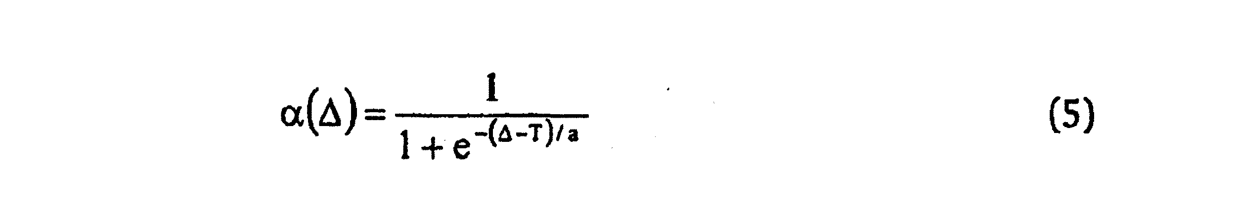
3つの異なる重み関数106、108、110を図9に示す。これらの関数は、方程式(5)によって与えられる一般的な関数に対応する。
The
The function α (Δ) can be stored as a lookup table and generates a value of α (Δ) in the range [0, 1].
Three different weight functions 106, 108, 110 are shown in FIG. These functions correspond to the general functions given by equation (5).
ここで、a及びTは、可変パラメータである。
主観的評価及び客観的PSNR(ピーク信号対雑音比)値を使用してテスト画像でトレーニングされた、α(Δ)の最終参照表を以下の表2に提供する。
この表は、「読み出し順序」(すなわち、左から右へ、上から下へ)で提示されている。
Here, a and T are variable parameters.
The final look-up table for α (Δ), trained on the test images using subjective evaluation and objective PSNR (peak signal to noise ratio) values, is provided in Table 2 below.
The table is presented in “reading order” (ie, left to right, top to bottom).
他の実施の形態は、特許請求の範囲の範囲内にある。 Other embodiments are within the scope of the claims.
たとえば、上記圧縮アーティファクト低減の実施の形態は、ブロック変換ベースの画像圧縮方法によって圧縮された画像12に関して説明されているが、これらの実施の形態は、ブロック変換ベースでない他の画像圧縮技法によって圧縮された画像のアーティファクトを低減するのに容易に使用することができる。 For example, although the compression artifact reduction embodiments described above are described with respect to image 12 compressed by a block transform-based image compression method, these embodiments are compressed by other image compression techniques that are not block transform-based. Can be easily used to reduce artifacts in the rendered image.
80・・・ベース画像ジェネレータ,
82・・・リンギング補正画像ジェネレータ,
98・・・加重和ジェネレータ,
100・・・重みジェネレータ,
80 ... Base image generator,
82 ... Ringing correction image generator,
98 ... weighted sum generator,
100 ... weight generator,
Claims (10)
前記入力画像(12)の空間シフトフォワード変換を計算して、各組のフォワード変換係数(C1、C2、…、CK)を生成することと、
各組の前記フォワード変換係数(C1、C2、…、CK)に、非線形変換(T1、T2、…、TK)を適用することと、
前記各組の非線形変換されたフォワード変換係数の逆変換(C'1、C'2、…、C'K)を計算して、各中間画像(I1、I2、…、IK)を生成することと、
前記中間画像(I1、I2、…、IK)に基づいて、ベース画像(84)を生成することと、
前記中間画像(I1、I2、…、IK)それぞれのピクセルとそのピクセル以外の1つ以上のピクセルから、それぞれのピクセルの空間分散を空間強度変動の測度として計算することと、
前記空間強度変数の測度から、リンギング補正画像(86)を生成することと、
前記生成されたベース画像と前記リンギング補正画像とに基づいて、リンギングアーティファクトを低減した出力画像(40)を生成することと
を含む方法。A method for processing an input image (12), comprising:
Calculating a spatial shift forward transform of the input image (12) to generate each set of forward transform coefficients (C1, C2,..., CK);
Applying a non-linear transformation (T1, T2,..., TK) to each set of the forward transform coefficients (C1, C2,..., CK);
Calculating the inverse transform (C′1, C′2,..., C′K) of each set of nonlinearly transformed forward transform coefficients to generate each intermediate image (I1, I2,..., IK); When,
Generating a base image (84) based on the intermediate images (I1, I2, ..., IK);
Calculating the spatial variance of each pixel as a measure of spatial intensity variation from each pixel of the intermediate image (I1, I2,..., IK) and one or more pixels other than the pixel;
Generating a ringing correction image (86) from the measure of the spatial intensity variable;
Generating an output image (40) with reduced ringing artifacts based on the generated base image and the ringing corrected image.
請求項1に記載の方法。The method according to claim 1, wherein the calculated spatial shift forward transform (C1, C2, ..., CK) is a two-dimensional block discrete cosine transform.
請求項1に記載の方法。The non-linear transformation compares the absolute value of each of the forward transform coefficients (C1, C2,..., CK) with the respective threshold value for the forward transform coefficient, and the forward transform coefficient is determined from the threshold value. The method according to claim 1, wherein the forward transform coefficient is set to 0 when the value is smaller, and the coefficient is not changed otherwise.
前記フォワード変換係数(C1、C2、…、CK)を鮮鋭化すること
をさらに含む請求項3に記載の方法。By increasing the threshold value for the forward transform coefficient having a higher spatial frequency than the threshold value for the forward transform coefficient having a lower spatial frequency
The method of claim 3, further comprising sharpening the forward transform coefficients (C1, C2, ..., CK).
前記ベース画像(84)は、前記ベース画像の各ピクセル位置に対応する前記中間画像(I1、I2、…、IK)のピクセル値の各平均値を、各ピクセル位置のピクセル値として有する
請求項1に記載の方法。Generating the base image based on the intermediate images (I1, I2,..., IK) combines the intermediate images (I1, I2,..., IK) to calculate a base image (84). That is,
The said base image (84) has each average value of the pixel value of the said intermediate image (I1, I2, ..., IK) corresponding to each pixel position of the said base image as a pixel value of each pixel position. The method described in 1.
請求項5に記載の方法。The method of claim 5, wherein each pixel in the ringing correction image (86) is associated with a respective pixel of the intermediate image (I1, I2, ..., IK).
請求項6に記載の方法。The ringing correction image (86) is the smallest measure of the calculated spatial intensity variation measures of the pixels of the intermediate image (I1, I2,..., IK) corresponding to each pixel position of the ringing correction image. As a pixel value at each pixel location.
請求項6に記載の方法。The ringing correction image (86) is an average value of the corresponding intermediate image pixels at a minimum percentage of the calculated spatial variation measure of a plurality of pixels of the intermediate image corresponding to each pixel location of the ringing correction image. As a pixel value at each pixel location.
前記ベース画像(84)の所与のピクセルを取り囲む局所的な領域の局所的なコントラストの測度を計算することと、
前記局所的な領域を取り囲む前記ベース画像(84)のより大きな領域のブロックコントラストの測度を計算することと、
前記出力画像(40)の各ピクセル位置に対応する前記ベース画像(84)及び前記リンギング補正画像(86)それぞれのピクセル値に重み付けするための係数を、前記局所的なコントラストの測度と前記ブロックコントラストの測度とから計算することと、
前記計算された係数を用いてそれぞれ重み付けされた前記ベース画像と前記リンギング補正画像とを結合することと
を含む
請求項6に記載の方法。Generating the output image comprises:
Calculating a local contrast measure of a local region surrounding a given pixel of the base image (84);
Calculating a measure of block contrast of a larger area of the base image (84) surrounding the local area;
Coefficients for weighting the pixel values of the base image (84) and the ringing correction image (86) corresponding to the pixel positions of the output image (40) are used as the local contrast measure and the block contrast. Calculating from the measure of
7. The method of claim 6, comprising combining the base image and the ringing correction image, each weighted using the calculated coefficients.
前記入力画像の空間シフトフォワード変換を計算して、各組のフォワード変換係数(C1、C2、…、CK)を生成するように構成されたフォワード変換モジュール(66)と、
各組の前記フォワード変換係数(C1、C2、…、CK)に、非線形変換(T1、T2、…、TK)を適用するように構成された非線形ノイズ除去モジュール(68)と、
前記各組の非線形変換されたフォワード変換係数の逆変換(C'1、C'2、…、C'K)を計算して、各中間画像(I1、I2、…、IK)を生成するように構成された逆変換モジュールと、
前記中間画像(I1、I2、…、IK)に基づいて、ベース画像(84)を生成するように構成されたベース画像ジェネレータモジュールと、
前記中間画像(I1、I2、…、IK)のそれぞれのピクセルとそのピクセル以外の1つ以上のピクセルから、それぞれのピクセルの空間分散を空間強度変動の各測度として計算し、前記計算された空間強度変数の各測度から、リンギング補正画像(86)を生成するように構成されたリンギング補正画像ジェネレータモジュールと、
前記生成されたベース画像とリンギング補正画像とに基づいて、リンギングアーティファクトを低減した出力画像(40)を生成するように構成された出力画像ジェネレータモジュールと
を備えるシステム。A system for processing an input image (12),
A forward transform module (66) configured to calculate a spatial shift forward transform of the input image to generate each set of forward transform coefficients (C1, C2,..., CK);
A non-linear noise removal module (68) configured to apply a non-linear transform (T1, T2,..., TK) to each set of the forward transform coefficients (C1, C2,..., CK);
Inverse transforms (C′1, C′2,..., C′K) of the non-linearly transformed forward transform coefficients are calculated to generate intermediate images (I1, I2,..., IK). An inverse conversion module configured in
A base image generator module configured to generate a base image (84) based on the intermediate images (I1, I2, ..., IK);
From each pixel of the intermediate image (I1, I2,..., IK) and one or more pixels other than the pixel, the spatial dispersion of each pixel is calculated as each measure of spatial intensity variation, and the calculated space A ringing correction image generator module configured to generate a ringing correction image (86) from each measure of the intensity variable;
An output image generator module configured to generate an output image (40) with reduced ringing artifacts based on the generated base image and ringing correction image.
Applications Claiming Priority (2)
| Application Number | Priority Date | Filing Date | Title |
|---|---|---|---|
| US10/683,322 US7643688B2 (en) | 2003-10-10 | 2003-10-10 | Reducing artifacts in compressed images |
| PCT/US2004/032483 WO2005039187A1 (en) | 2003-10-10 | 2004-09-29 | Reducing artifacts in compressed images |
Publications (2)
| Publication Number | Publication Date |
|---|---|
| JP2007508744A JP2007508744A (en) | 2007-04-05 |
| JP4468367B2 true JP4468367B2 (en) | 2010-05-26 |
Family
ID=34422715
Family Applications (1)
| Application Number | Title | Priority Date | Filing Date |
|---|---|---|---|
| JP2006534176A Expired - Fee Related JP4468367B2 (en) | 2003-10-10 | 2004-09-29 | Reduce artifacts in compressed images |
Country Status (4)
| Country | Link |
|---|---|
| US (1) | US7643688B2 (en) |
| JP (1) | JP4468367B2 (en) |
| GB (1) | GB2422743B (en) |
| WO (1) | WO2005039187A1 (en) |
Families Citing this family (24)
| Publication number | Priority date | Publication date | Assignee | Title |
|---|---|---|---|---|
| AU2003247030A1 (en) * | 2002-07-31 | 2004-02-23 | Koninklijke Philips Electronics N.V. | Dynamic detection of blocking artefacts |
| US7388999B2 (en) * | 2003-10-29 | 2008-06-17 | Hewlett-Packard Development Company, L.P. | Transformations for denoising images |
| US8594448B2 (en) * | 2004-08-16 | 2013-11-26 | Hewlett-Packard Development Company, L.P. | Bi-selective filtering in transform domain |
| US7684632B2 (en) * | 2005-05-16 | 2010-03-23 | Hewlett-Packard Development Company, L.P. | Estimating image compression quantization parameter values |
| US8050331B2 (en) * | 2005-05-20 | 2011-11-01 | Ntt Docomo, Inc. | Method and apparatus for noise filtering in video coding |
| US7760805B2 (en) | 2005-05-31 | 2010-07-20 | Hewlett-Packard Development Company, L.P. | Method of enhancing images extracted from video |
| JP5011519B2 (en) * | 2005-07-05 | 2012-08-29 | 国立大学法人東京工業大学 | Signal reading method and image signal processing method of solid-state imaging device |
| US20070041448A1 (en) * | 2005-08-17 | 2007-02-22 | Miller Casey L | Artifact and noise reduction in MPEG video |
| US7868950B1 (en) | 2006-04-17 | 2011-01-11 | Hewlett-Packard Development Company, L.P. | Reducing noise and artifacts in an image |
| TWI332351B (en) * | 2006-10-05 | 2010-10-21 | Realtek Semiconductor Corp | Image processing method and device thereof for reduction mosquito noise |
| US7965900B2 (en) | 2007-09-26 | 2011-06-21 | Hewlett-Packard Development Company, L.P. | Processing an input image to reduce compression-related artifacts |
| US8285068B2 (en) | 2008-06-25 | 2012-10-09 | Cisco Technology, Inc. | Combined deblocking and denoising filter |
| US8571117B2 (en) * | 2009-06-05 | 2013-10-29 | Cisco Technology, Inc. | Out of loop frame matching in 3D-based video denoising |
| US8615044B2 (en) * | 2009-06-05 | 2013-12-24 | Cisco Technology, Inc. | Adaptive thresholding of 3D transform coefficients for video denoising |
| US8520731B2 (en) * | 2009-06-05 | 2013-08-27 | Cisco Technology, Inc. | Motion estimation for noisy frames based on block matching of filtered blocks |
| US8638395B2 (en) | 2009-06-05 | 2014-01-28 | Cisco Technology, Inc. | Consolidating prior temporally-matched frames in 3D-based video denoising |
| US8358380B2 (en) * | 2009-06-05 | 2013-01-22 | Cisco Technology, Inc. | Efficient spatial and temporal transform-based video preprocessing |
| US8619881B2 (en) * | 2009-06-05 | 2013-12-31 | Cisco Technology, Inc. | Estimation of temporal depth of 3D overlapped transforms in video denoising |
| US9628674B2 (en) | 2010-06-02 | 2017-04-18 | Cisco Technology, Inc. | Staggered motion compensation for preprocessing video with overlapped 3D transforms |
| US9635308B2 (en) | 2010-06-02 | 2017-04-25 | Cisco Technology, Inc. | Preprocessing of interlaced video with overlapped 3D transforms |
| US8472725B2 (en) | 2010-06-02 | 2013-06-25 | Cisco Technology, Inc. | Scene change detection and handling for preprocessing video with overlapped 3D transforms |
| US8983206B2 (en) | 2011-05-04 | 2015-03-17 | Ecole de Techbologie Superieure | Method and system for increasing robustness of visual quality metrics using spatial shifting |
| US9832351B1 (en) | 2016-09-09 | 2017-11-28 | Cisco Technology, Inc. | Reduced complexity video filtering using stepped overlapped transforms |
| US10083499B1 (en) * | 2016-10-11 | 2018-09-25 | Google Llc | Methods and apparatus to reduce compression artifacts in images |
Family Cites Families (24)
| Publication number | Priority date | Publication date | Assignee | Title |
|---|---|---|---|---|
| US4754492A (en) | 1985-06-03 | 1988-06-28 | Picturetel Corporation | Method and system for adapting a digitized signal processing system for block processing with minimal blocking artifacts |
| US5046121A (en) * | 1989-01-31 | 1991-09-03 | Konica Corporation | Image data compression apparatus |
| US5454051A (en) | 1991-08-05 | 1995-09-26 | Eastman Kodak Company | Method of reducing block artifacts created by block transform compression algorithms |
| US5526446A (en) * | 1991-09-24 | 1996-06-11 | Massachusetts Institute Of Technology | Noise reduction system |
| US5311305A (en) * | 1992-06-30 | 1994-05-10 | At&T Bell Laboratories | Technique for edge/corner detection/tracking in image frames |
| JP3466705B2 (en) | 1993-05-28 | 2003-11-17 | ゼロックス・コーポレーション | How to decompress compressed images |
| US5359676A (en) * | 1993-07-19 | 1994-10-25 | Xerox Corporation | Decompression of standard ADCT-compressed document images |
| US5940536A (en) * | 1995-09-05 | 1999-08-17 | Matsushita Electric Industrial Co., Ltd. | Ringing detector and filter |
| US5737451A (en) * | 1996-04-10 | 1998-04-07 | Eastman Kodak Company | Method and apparatus for suppressing blocking artifacts in block-transform coded images |
| KR100213089B1 (en) * | 1997-01-29 | 1999-08-02 | 윤종용 | Loop filtering method and loop filter |
| JP3800704B2 (en) * | 1997-02-13 | 2006-07-26 | ソニー株式会社 | Video signal processing apparatus and method |
| DE19835451B4 (en) * | 1997-08-20 | 2005-03-24 | Siemens Ag | Method for a computer tomograph for post-processing a sectional image and computer tomograph operating according to this method |
| KR100308016B1 (en) * | 1998-08-31 | 2001-10-19 | 구자홍 | Block and Ring Phenomenon Removal Method and Image Decoder in Compressed Coded Image |
| IT1305196B1 (en) | 1998-11-20 | 2001-04-10 | Cit Alcatel | METHOD OF REDUCTION OF ARTIFACTS OF CODING IN BLOCKED VIDEO-CODED SIGNALS. |
| US6317522B1 (en) * | 1998-12-03 | 2001-11-13 | Philips Electronics North America Corp. | Systems and methods for post-processing decompressed images |
| US6427031B1 (en) | 1998-12-31 | 2002-07-30 | Eastman Kodak Company | Method for removing artifacts in an electronic image decoded from a block-transform coded representation of an image |
| US6563964B1 (en) | 1999-02-08 | 2003-05-13 | Sharp Laboratories Of America, Inc. | Image downsampling using redundant pixel removal |
| US6748113B1 (en) * | 1999-08-25 | 2004-06-08 | Matsushita Electric Insdustrial Co., Ltd. | Noise detecting method, noise detector and image decoding apparatus |
| EP1209624A1 (en) * | 2000-11-27 | 2002-05-29 | Sony International (Europe) GmbH | Method for compressed imaging artefact reduction |
| US7003173B2 (en) * | 2001-06-12 | 2006-02-21 | Sharp Laboratories Of America, Inc. | Filter for combined de-ringing and edge sharpening |
| US6983079B2 (en) * | 2001-09-20 | 2006-01-03 | Seiko Epson Corporation | Reducing blocking and ringing artifacts in low-bit-rate coding |
| US7031552B2 (en) * | 2002-04-05 | 2006-04-18 | Seiko Epson Corporation | Adaptive post-filtering for reducing noise in highly compressed image/video coding |
| US7139437B2 (en) * | 2002-11-12 | 2006-11-21 | Eastman Kodak Company | Method and system for removing artifacts in compressed images |
| US20040208389A1 (en) * | 2003-04-15 | 2004-10-21 | Silicon Integrated Systems Corp. | Digital picture processing method |
-
2003
- 2003-10-10 US US10/683,322 patent/US7643688B2/en not_active Expired - Fee Related
-
2004
- 2004-09-29 WO PCT/US2004/032483 patent/WO2005039187A1/en active Application Filing
- 2004-09-29 JP JP2006534176A patent/JP4468367B2/en not_active Expired - Fee Related
- 2004-09-29 GB GB0607195A patent/GB2422743B/en not_active Expired - Fee Related
Also Published As
| Publication number | Publication date |
|---|---|
| US20050078872A1 (en) | 2005-04-14 |
| GB2422743B (en) | 2007-10-17 |
| WO2005039187A1 (en) | 2005-04-28 |
| GB2422743A (en) | 2006-08-02 |
| JP2007508744A (en) | 2007-04-05 |
| GB0607195D0 (en) | 2006-05-17 |
| US7643688B2 (en) | 2010-01-05 |
Similar Documents
| Publication | Publication Date | Title |
|---|---|---|
| JP4468367B2 (en) | Reduce artifacts in compressed images | |
| JP4987480B2 (en) | Conversion to remove image noise | |
| US7760805B2 (en) | Method of enhancing images extracted from video | |
| JP4714668B2 (en) | Improving the quality of compressed images | |
| US6473533B1 (en) | Image encoding apparatus and image decoding apparatus | |
| US6650786B2 (en) | Image encoding apparatus and image decoding apparatus | |
| US7302104B2 (en) | Smoothing tile boundaries of images encoded and decoded by JPEG 2000 | |
| EP2201778B1 (en) | Processing an input image to reduce compression-related artifacts | |
| EP1420363A2 (en) | Method and apparatus for removing artifacts in compressed images | |
| US20040208392A1 (en) | Method and apparatus for improving video quality of low bit-rate video | |
| JP4066367B2 (en) | Image noise removal method | |
| WO2006036796A1 (en) | Processing video frames | |
| US6665447B1 (en) | Method for enhancing image data by sharpening | |
| JP3732674B2 (en) | Color image compression method and color image compression apparatus | |
| JP4784386B2 (en) | Decoding device, inverse quantization method, and program | |
| Shao | Simultaneous coding artifact reduction and sharpness enhancement for block-based compressed images and videos | |
| JP3034887B2 (en) | Image processing method and apparatus | |
| Silverstein et al. | Restoration of compressed images | |
| JP4424672B2 (en) | Image processing apparatus, image processing method, program, and information recording medium | |
| Wong | PECSI: a practical perceptually-enhanced compression framework for still images | |
| Hsieh et al. | Application of grey polynomial interpolation to reduce the block effect in low bit rate coding |
Legal Events
| Date | Code | Title | Description |
|---|---|---|---|
| A131 | Notification of reasons for refusal |
Free format text: JAPANESE INTERMEDIATE CODE: A131 Effective date: 20080731 |
|
| A601 | Written request for extension of time |
Free format text: JAPANESE INTERMEDIATE CODE: A601 Effective date: 20081029 |
|
| A602 | Written permission of extension of time |
Free format text: JAPANESE INTERMEDIATE CODE: A602 Effective date: 20081106 |
|
| A521 | Request for written amendment filed |
Free format text: JAPANESE INTERMEDIATE CODE: A523 Effective date: 20090127 |
|
| A521 | Request for written amendment filed |
Free format text: JAPANESE INTERMEDIATE CODE: A821 Effective date: 20090128 |
|
| A131 | Notification of reasons for refusal |
Free format text: JAPANESE INTERMEDIATE CODE: A131 Effective date: 20090303 |
|
| A02 | Decision of refusal |
Free format text: JAPANESE INTERMEDIATE CODE: A02 Effective date: 20090715 |
|
| A521 | Request for written amendment filed |
Free format text: JAPANESE INTERMEDIATE CODE: A523 Effective date: 20091112 |
|
| A521 | Request for written amendment filed |
Free format text: JAPANESE INTERMEDIATE CODE: A821 Effective date: 20091112 |
|
| A911 | Transfer to examiner for re-examination before appeal (zenchi) |
Free format text: JAPANESE INTERMEDIATE CODE: A911 Effective date: 20091211 |
|
| TRDD | Decision of grant or rejection written | ||
| A01 | Written decision to grant a patent or to grant a registration (utility model) |
Free format text: JAPANESE INTERMEDIATE CODE: A01 Effective date: 20100216 |
|
| A01 | Written decision to grant a patent or to grant a registration (utility model) |
Free format text: JAPANESE INTERMEDIATE CODE: A01 |
|
| A61 | First payment of annual fees (during grant procedure) |
Free format text: JAPANESE INTERMEDIATE CODE: A61 Effective date: 20100224 |
|
| R150 | Certificate of patent or registration of utility model |
Ref document number: 4468367 Country of ref document: JP Free format text: JAPANESE INTERMEDIATE CODE: R150 Free format text: JAPANESE INTERMEDIATE CODE: R150 |
|
| FPAY | Renewal fee payment (event date is renewal date of database) |
Free format text: PAYMENT UNTIL: 20130305 Year of fee payment: 3 |
|
| FPAY | Renewal fee payment (event date is renewal date of database) |
Free format text: PAYMENT UNTIL: 20140305 Year of fee payment: 4 |
|
| R250 | Receipt of annual fees |
Free format text: JAPANESE INTERMEDIATE CODE: R250 |
|
| R250 | Receipt of annual fees |
Free format text: JAPANESE INTERMEDIATE CODE: R250 |
|
| R250 | Receipt of annual fees |
Free format text: JAPANESE INTERMEDIATE CODE: R250 |
|
| R250 | Receipt of annual fees |
Free format text: JAPANESE INTERMEDIATE CODE: R250 |
|
| R250 | Receipt of annual fees |
Free format text: JAPANESE INTERMEDIATE CODE: R250 |
|
| R250 | Receipt of annual fees |
Free format text: JAPANESE INTERMEDIATE CODE: R250 |
|
| R250 | Receipt of annual fees |
Free format text: JAPANESE INTERMEDIATE CODE: R250 |
|
| R250 | Receipt of annual fees |
Free format text: JAPANESE INTERMEDIATE CODE: R250 |
|
| LAPS | Cancellation because of no payment of annual fees |